CPE 100L DIGITAL LOGIC DESIGN I DESIGN LABORATORY LABORATORY 1 LAB SAFETY QUIZ & LAB EQUIPMENT USE TUTORIAL UNIVERSITY OF NEVADA, LAS VEGAS GOALS:
|
|
|
- Lora Karen Cummings
- 5 years ago
- Views:
Transcription
1 CPE 100L DESIGN LABORATORY LABORATORY 1 LAB SAFETY QUIZ & LAB EQUIPMENT USE TUTORIAL DEPARTMENT OF ELECTRICAL AND COMPUTER ENGINEERING UNIVERSITY OF NEVADA, LAS VEGAS GOALS: Introduce laboratory safety procedures to safeguard lives and properties. Provide a basic tutorial on the functions of laboratory equipment that will be utilized during the term. Upon conclusion of this work, the student will be familiar with safe lab working procedure and with the basic setup of the equipment used in this laboratory class experiments. SAFETY: Safety is the most important issue that impacts successful implementation of any lab experiments. Improper equipment usage not only damage property, it can potentially jeopardize your life as well lives of the fellow students. Carefully read the safety manual posted on class website. After reading the safety manual, you must take the safety exam and pass the exam to continue the class. Note: Your negligence in following the safety guidelines anytime during the semester will not be tolerated and you would be dropped from the class. LAB SCHEDULE: The plan for Lab#1 is as follows: 1. Laboratory safety exam 2. Work with each equipment unit using below instructions 3. Using knowledge learned during 2., do lab experiments listed at the end of this instruction. DEPARTMENT OF ELECTRICAL AND COMPUTER ENGINEERING 1

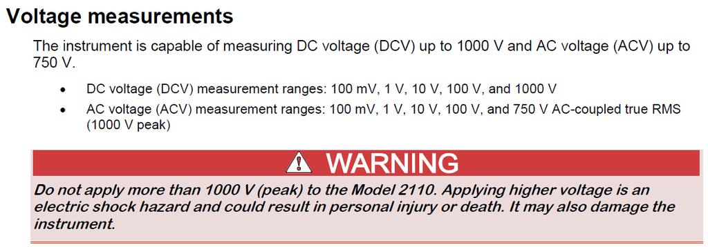
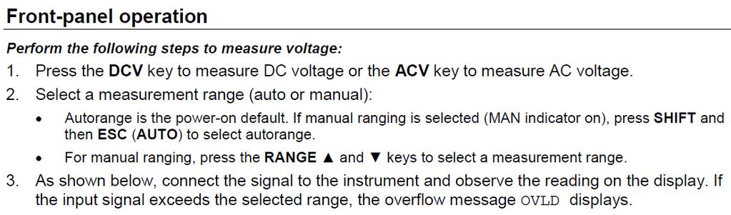
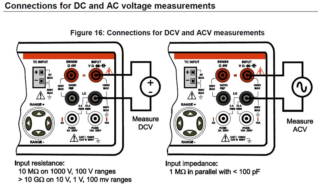
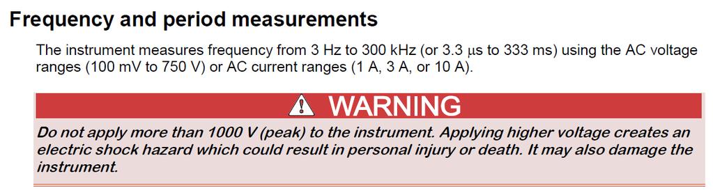
2 EQUIPMENT USE: The following equipment is located at each station: Keithley-DMM ½ Digit Multimeter Figure 1 Front Panel of Keithley-DMM ½ Digit Multimeter Display Power Key Function and operation keys RANGE and scroll keys TC input Terminal and fuses Connections for different measurements as follows: DEPARTMENT OF ELECTRICAL AND COMPUTER ENGINEERING 2
3 DEPARTMENT OF ELECTRICAL AND COMPUTER ENGINEERING 3

4 DEPARTMENT OF ELECTRICAL AND COMPUTER ENGINEERING 4

5 DEPARTMENT OF ELECTRICAL AND COMPUTER ENGINEERING 5
6 DEPARTMENT OF ELECTRICAL AND COMPUTER ENGINEERING 6
7 DEPARTMENT OF ELECTRICAL AND COMPUTER ENGINEERING 7
8 DC Power Supply HY3000 Series Figure 2 Front Panel of DC Power Supply HY3000 Series DEPARTMENT OF ELECTRICAL AND COMPUTER ENGINEERING 8


9 DEPARTMENT OF ELECTRICAL AND COMPUTER ENGINEERING 9
10 DEPARTMENT OF ELECTRICAL AND COMPUTER ENGINEERING 10


11 GW Instek Arbitrary Function Generator AFG-2225 Figure 3 Front Panel of GW Instek AFG-2225 DEPARTMENT OF ELECTRICAL AND COMPUTER ENGINEERING 11

12 DEPARTMENT OF ELECTRICAL AND COMPUTER ENGINEERING 12


13 DEPARTMENT OF ELECTRICAL AND COMPUTER ENGINEERING 13


14 DEPARTMENT OF ELECTRICAL AND COMPUTER ENGINEERING 14

15 DEPARTMENT OF ELECTRICAL AND COMPUTER ENGINEERING 15

16 DEPARTMENT OF ELECTRICAL AND COMPUTER ENGINEERING 16


17 Tektronix MSO2000 Series Oscilloscope DEPARTMENT OF ELECTRICAL AND COMPUTER ENGINEERING 17
18 DEPARTMENT OF ELECTRICAL AND COMPUTER ENGINEERING 18


19 DEPARTMENT OF ELECTRICAL AND COMPUTER ENGINEERING 19
20 And MORE!! DEPARTMENT OF ELECTRICAL AND COMPUTER ENGINEERING 20

21 DEPARTMENT OF ELECTRICAL AND COMPUTER ENGINEERING 21

22 DEPARTMENT OF ELECTRICAL AND COMPUTER ENGINEERING 22
23 DEPARTMENT OF ELECTRICAL AND COMPUTER ENGINEERING 23
24 Tektronix TDS2000C Series Oscilloscope DEPARTMENT OF ELECTRICAL AND COMPUTER ENGINEERING 24
25 DEPARTMENT OF ELECTRICAL AND COMPUTER ENGINEERING 25
26 DEPARTMENT OF ELECTRICAL AND COMPUTER ENGINEERING 26


27 Connecting oscilloscope and function generator The oscilloscope probe is the only thing you can connect to the oscilloscope: Oscilloscope probe The function generation cable can be only connected to function generator: Function generator cable Remember that you CANNOT connect function generator cable to oscilloscope. DEPARTMENT OF ELECTRICAL AND COMPUTER ENGINEERING 27
28 LAB DELIVERIES: PRELAB: Equipment Usage: Review video lectures on equipment usage posted on the class website. Lab Experiments: For experiments 1-4, record all the steps as a write-down list, and take a picture of the result. Experiment 1: DC Power Supply Set Up with Multimeter Goal: connecting DC power supply to the multimeter changing the power supply output values and verifying them on the multimeter. a) Turn on power supply with Power and Output Switch buttons, and also power on the multimeter b) Turn both the Current and Voltage knobs of Channel 1 fully counter clockwise c) Use black wire/cable to connect the - port of power supply CH1 to the com on the multimeter, and use red wire/cable to connect the + end of power supply CH1 to the V input of the multimeter. Observe and write down the readings of both power supply CH1 and multimeter. d) Slowly turn, clockwise, the Current knob of CH1 on power supply, until C.C LED turns off, and C.V LED goes on. Observe the readings of both power supply CH1 and multimeter. e) Slowly turn, clockwise, the Voltage knob of CH1 on power supply, and see if readings on power supply CH1 and multimeter are the same. Continue doing so, SLOWLY, until the Voltage reading stop increasing. Write down the maximum voltage reading (30.6V). Experiment 2: DC Power Supply Set Up with Oscilloscope Goal: connecting DC power supply to the oscilloscope measuring DC power supply output voltage with the oscilloscope a) Turn on oscilloscope and press Autoset. Perform the self-detection of both coax measurement probe and oscilloscope. Adjust probe for capacity compensation if necessary. b) Connect the coax measurement probe from Channel 1 to the output of the power supply. Connect the hook of coax probe to the positive output of the power, and the clipper of the coax probe to the negative output of the power. c) On the power supply, turn both the Current and Voltage knobs of Channel 1 fully counter clockwise, then turn on the power supply d) Slowly adjust the power supply voltage from 0V to 10V. Observe the changes on the oscilloscope. Press Autoset when necessary (e.g. trace goes off the grid or unstable) e) Press the yellow button of CH1. Change Coupling-DC to AC, and see what happens. DEPARTMENT OF ELECTRICAL AND COMPUTER ENGINEERING 28
29 Choose the Oscilloscope you have at your workstation: (TBE-B311 MSO2014B): f) Press Probe Setup, and toggle between Set to 1X and Set to 10X. See what happens. (Vertical grid 5V 500mV) (TBE-B350 TDS2014): g) In Probe, toggle between 1X and 10X. See what happens. (Vertical grid 5V 500mV) h) Turn the Vertical-Scale and Vertical-Position knob of CH1, clockwise or counter clockwise, and see what happens (Vertical grid scales). i) Turn the Horizontal-Scale and Horizontal -Position knob of CH1, clockwise or counter clockwise, and see what happens (Horizontal grid scales). j) Adjust the power supply voltage to 5.0V and then to 10.0V. The trace on the oscilloscope should reflect the change k) Experiment with other power supply voltages and change the Volts/Div knob accordingly in order to indicate the value on the oscilloscope. Experiment 3: Signal Generator Setup with Oscilloscope Goal: Setting up the function generator Connecting the function generator to the oscilloscope Verifying the function generator setting on the oscilloscope display a) Initially set up the signal generator with the following parameters (be sure the CH1 Coupling is DC and do not change the other oscilloscope settings) and measure the output with Oscilloscope. Set: Frequency: 1kHz Amplitude: 1V Offset: 0V b) Change the signal generator output to the following, and observe the waveform on the Oscilloscope. Set: Frequency: 2kHz Amplitude: 0.5V Offset: 1V c) Change the Oscilloscope to AC coupling, and observe the results. Experiment 4: measuring resistance with multimeter a) Take one resistor of any value below 1000Ω (1kΩ) from the laboratory bin, set the multimeter function to Ω2 b) Set the range of the multimeter to 1KOHM. c) Connect red banana cable to HI Input VΩ, black banana cable to black connector LO d) Connect resistor to remaining banana ends. e) Read the value of the resistance from the display, compare with declared resistor value. DEPARTMENT OF ELECTRICAL AND COMPUTER ENGINEERING 29
30 Experiment 5 (Optional if asked by TA): Demonstrate the following to TA: 1. Power Supply: o Show: how to set up the supply for positive and negative valued voltages. o Show: proper set-up of the ground. 2. Function Generator: o Show: how to set a given frequency and amplitude. o Show: how to provide a DC offset. o Answer: what is the difference between Main and Sync outputs. 3. Multimeter: o Show: how to measure voltage and resistance. o Answer: how to properly use the range settings. o Answer: When is the multi-meter the appropriate instrument and when it is not 4. Oscilloscope o Show: how to adjust probe. o Show: how to properly display a wave shape(s). o Show: how to measure voltage and frequency (with cursors and division counting) POSTLAB REPORT: Include the following elements in the report document: Section Element 1 Theory of operation Include a brief description of every element and phenomenon that appears during the experiments. Results of the experiments Experiment Experiment Results 2 a. Description of what you have measured during the lab 1 b. Picture(s) of the setup c. Obtained results a. Description of what you have measured during the lab 2 b. Picture(s) of the setup c. Obtained results a. Description of what you have measured during the lab 3 b. Picture(s) of the setup c. Obtained results a. Description of what you have measured during the lab 4 b. Picture(s) of the setup c. Obtained results For all the Show questions, provide brief description, picture of the setup 5 and obtained results. Answer the questions Question no. Question 3 1 What is ground and why it s used in electrical circuits? What is the difference between oscilloscope probe and function generator 2 cable? (include pictures, it s allowed to use pictures from the Internet) 3 What is Autoset function of the oscilloscope? 4 Conclusions Write down your conclusions, things learned, problems encountered during the lab and how they were solved, etc. DEPARTMENT OF ELECTRICAL AND COMPUTER ENGINEERING 30
CPE 310L EMBEDDED SYSTEM DESIGN LABORATORY
 CPE 310L EMBEDDED SYSTEM DESIGN LABORATORY LABORATORY 1 LAB SAFETY & LAB EQUIPMENT USE TUTORIAL DEPARTMENT OF ELECTRICAL AND COMPUTER ENGINEERING UNIVERSITY OF NEVADA, LAS VEGAS GOALS: Introduce laboratory
EE/CPE LABORATORY 1 LAB SAFETY & LAB EQUIPMENT USE TUTORIAL. by Ming Zhu UNIVERSITY OF NEVADA, LAS VEGAS 1. OBJECTIVE 2. COMPONENTS & EQUIPMENT
 EE/CPE LABORATORY 1 LAB SAFETY & LAB EQUIPMENT USE TUTORIAL by Ming Zhu DEPARTMENT OF ELECTRICAL AND COMPUTER ENGINEERING UNIVERSITY OF NEVADA, LAS VEGAS 1. OBJECTIVE Introduce laboratory safety procedures
Laboratory Equipment Instruction Manual 2011
 University of Toronto Department of Electrical and Computer Engineering Instrumentation Laboratory GB341 Laboratory Equipment Instruction Manual 2011 Page 1. Wires and Cables A-2 2. Protoboard A-3 3. DC
Introduction to basic laboratory instruments
 BEE 233 Laboratory-1 Introduction to basic laboratory instruments 1. Objectives To learn safety procedures in the laboratory. To learn how to use basic laboratory instruments: power supply, function generator,
EE 210: CIRCUITS AND DEVICES
 EE 210: CIRCUITS AND DEVICES LAB #3: VOLTAGE AND CURRENT MEASUREMENTS This lab features a tutorial on the instrumentation that you will be using throughout the semester. More specifically, you will see
Sept 13 Pre-lab due Sept 12; Lab memo due Sept 19 at the START of lab time, 1:10pm
 Sept 13 Pre-lab due Sept 12; Lab memo due Sept 19 at the START of lab time, 1:10pm EGR 220: Engineering Circuit Theory Lab 1: Introduction to Laboratory Equipment Pre-lab Read through the entire lab handout
EECS 318 Electronics Lab Laboratory #2 Electronic Test Equipment
 EECS 318 Electronics Lab Laboratory #2 Electronic Test Equipment Objectives: The purpose of this laboratory is to acquaint you with the electronic sources and measuring equipment you will be using throughout
LAB 1: Familiarity with Laboratory Equipment (_/10)
") LAB 1: Familiarity with Laboratory Equipment (_/10) PURPOSE o gain familiarity with basic laboratory equipment oscilloscope, oscillator, multimeter and electronic components. EQUIPMEN (i) Oscilloscope
LAB 1: Familiarity with Laboratory Equipment (_/10) PURPOSE o gain familiarity with basic laboratory equipment oscilloscope, oscillator, multimeter and electronic components. EQUIPMEN (i) Oscilloscope
Lab 6 Instrument Familiarization
 Lab 6 Instrument Familiarization What You Need To Know: Voltages and currents in an electronic circuit as in a CD player, mobile phone or TV set vary in time. Throughout todays lab you will investigate
ECE 2274 Lab 1 (Intro)
") ECE 2274 Lab 1 (Intro) Richard Dumene: Spring 2018 Revised: Richard Cooper: Spring 2018 Forward (DO NOT TURN IN) The purpose of this lab course is to familiarize you with high-end lab equipment, and train
ECE 2274 Lab 1 (Intro) Richard Dumene: Spring 2018 Revised: Richard Cooper: Spring 2018 Forward (DO NOT TURN IN) The purpose of this lab course is to familiarize you with high-end lab equipment, and train
Introduction to basic laboratory instruments
 Introduction to basic laboratory instruments 1. OBJECTIVES... 2 2. LABORATORY SAFETY... 2 3. BASIC LABORATORY INSTRUMENTS... 2 4. USING A DC POWER SUPPLY... 2 5. USING A FUNCTION GENERATOR... 3 5.1 TURN
ENGR 1110: Introduction to Engineering Lab 7 Pulse Width Modulation (PWM)
") ENGR 1110: Introduction to Engineering Lab 7 Pulse Width Modulation (PWM) Supplies Needed Motor control board, Transmitter (with good batteries), Receiver Equipment Used Oscilloscope, Function Generator,
ENGR 1110: Introduction to Engineering Lab 7 Pulse Width Modulation (PWM) Supplies Needed Motor control board, Transmitter (with good batteries), Receiver Equipment Used Oscilloscope, Function Generator,
Introduction to Basic Laboratory Instruments
 Introduction to Contents: 1. Objectives... 2 2. Laboratory Safety... 2 3.... 2 4. Using a DC Power Supply... 2 5. Using a Function Generator... 3 5.1 Turn on the Instrument... 3 5.2 Setting Signal Type...
CHAPTER 6. Motor Driver
 CHAPTER 6 Motor Driver In this lab, we will construct the circuitry that your robot uses to drive its motors. However, before testing the motor circuit we will begin by making sure that you are able to
Experiment #2: Introduction to Lab Equipment: Function Generator, Oscilloscope, and Multisim
 SCHOOL OF ENGINEERING AND APPLIED SCIENCE DEPARTMENT OF ELECTRICAL AND COMPUTER ENGINEERING ECE 2110: CIRCUIT THEORY LABORATORY Experiment #2: Introduction to Lab Equipment: Function Generator, Oscilloscope,
EXPERIMENT 2 DIGITAL STORAGE OSCILLOSCOPE
 EXPERIMENT 2 DIGITAL STORAGE OSCILLOSCOPE 2.1 Objective: In this experiment, you will learn the basic usage of digital storage oscilloscope (DSO) of GW Instek Technologies. More specifically you will learn,
Lab 0: Introduction to basic laboratory instruments. Revised by Dan Hoang & Tai-Chang Chen 03/30/2009
 Lab 0: Introduction to basic laboratory instruments Revised by Dan Hoang & Tai-Chang Chen 03/30/2009 1. Objectives 1. To learn safety procedures in the laboratory. 2. To learn how to use basic laboratory
Introduction to Electronic Equipment
 Introduction to Electronic Equipment INTRODUCTION This semester you will be exploring electricity and magnetism. In order to make your time in here more instructive we ve designed this laboratory exercise
Equipment: You will use the bench power supply, function generator and oscilloscope.
 EE203 Lab #0 Laboratory Equipment and Measurement Techniques Purpose Your objective in this lab is to gain familiarity with the properties and effective use of the lab power supply, function generator
Faculty of Engineering, Thammasat University
 Faculty of Engineering, Thammasat University Experiment 6: Oscilloscope (For room 506) Objectives: 1. To familiarize you with the Oscilloscope and Function Generator User Manual: Oscilloscope 1 5 9 4 7
EENG-201 Experiment # 4: Function Generator, Oscilloscope
 EENG-201 Experiment # 4: Function Generator, Oscilloscope I. Objectives Upon completion of this experiment, the student should be able to 1. To become familiar with the use of a function generator. 2.
LABORATORY 4. Palomar College ENGR210 Spring 2017 ASSIGNED: 3/21/17
 LABORATORY 4 ASSIGNED: 3/21/17 OBJECTIVE: The purpose of this lab is to evaluate the transient and steady-state circuit response of first order and second order circuits. MINIMUM EQUIPMENT LIST: You will
UNIVERSITY OF CALIFORNIA, SANTA BARBARA Department of Electrical and Computer Engineering. ECE 2A & 2B Laboratory Equipment Information
 UNIVERSITY OF CALIFORNIA, SANTA BARBARA Department of Electrical and Computer Engineering ECE 2A & 2B Laboratory Equipment Information Table of Contents Digital Multi-Meter (DMM)... 1 Features... 1 Using
ME 365 EXPERIMENT 1 FAMILIARIZATION WITH COMMONLY USED INSTRUMENTATION
 Objectives: ME 365 EXPERIMENT 1 FAMILIARIZATION WITH COMMONLY USED INSTRUMENTATION The primary goal of this laboratory is to study the operation and limitations of several commonly used pieces of instrumentation:
ECE 53A: Fundamentals of Electrical Engineering I
 ECE 53A: Fundamentals of Electrical Engineering I Laboratory Assignment #1: Instrument Operation, Basic Resistor Measurements and Kirchhoff s Laws Fall 2007 General Guidelines: - Record data and observations
Physics 323. Experiment # 1 - Oscilloscope and Breadboard
 Physics 323 Experiment # 1 - Oscilloscope and Breadboard Introduction In order to familiarise yourself with the laboratory equipment, a few simple experiments are to be performed. References: XYZ s of
On-Line Students Analog Discovery 2: Arbitrary Waveform Generator (AWG). Two channel oscilloscope
. Two channel oscilloscope") EET 150 Introduction to EET Lab Activity 5 Oscilloscope Introduction Required Parts, Software and Equipment Parts Figure 1, Figure 2, Figure 3 Component /Value Quantity Resistor 10 kω, ¼ Watt, 5% Tolerance
EET 150 Introduction to EET Lab Activity 5 Oscilloscope Introduction Required Parts, Software and Equipment Parts Figure 1, Figure 2, Figure 3 Component /Value Quantity Resistor 10 kω, ¼ Watt, 5% Tolerance
On-Line Students Analog Discovery 2: Arbitrary Waveform Generator (AWG). Two channel oscilloscope
. Two channel oscilloscope") EET 150 Introduction to EET Lab Activity 8 Function Generator Introduction Required Parts, Software and Equipment Parts Figure 1 Component /Value Quantity Resistor 10 kω, ¼ Watt, 5% Tolerance 1 Resistor
EET 150 Introduction to EET Lab Activity 8 Function Generator Introduction Required Parts, Software and Equipment Parts Figure 1 Component /Value Quantity Resistor 10 kω, ¼ Watt, 5% Tolerance 1 Resistor
EGRE 101 DC Motor II
 EGRE 101 DC Motor II Preamble In this week s laboratory exercise you will become familiar with: Converting a circuit schematic to a physical circuit implementation Measuring physical quantities relevant
The Oscilloscope. Vision is the art of seeing things invisible. J. Swift ( ) OBJECTIVE To learn to operate a digital oscilloscope.
 OBJECTIVE To learn to operate a digital oscilloscope.") The Oscilloscope Vision is the art of seeing things invisible. J. Swift (1667-1745) OBJECTIVE To learn to operate a digital oscilloscope. THEORY The oscilloscope, or scope for short, is a device for drawing
The Oscilloscope Vision is the art of seeing things invisible. J. Swift (1667-1745) OBJECTIVE To learn to operate a digital oscilloscope. THEORY The oscilloscope, or scope for short, is a device for drawing
Name: First-Order Response: RC Networks Objective: To gain experience with first-order response of RC circuits
 First-Order Response: RC Networks Objective: To gain experience with first-order response of RC circuits Table of Contents: Pre-Lab Assignment 2 Background 2 National Instruments MyDAQ 2 Resistors 3 Capacitors
University of Jordan School of Engineering Electrical Engineering Department. EE 204 Electrical Engineering Lab
 University of Jordan School of Engineering Electrical Engineering Department EE 204 Electrical Engineering Lab EXPERIMENT 1 MEASUREMENT DEVICES Prepared by: Prof. Mohammed Hawa EXPERIMENT 1 MEASUREMENT
Agilent 33522A Function Arbitrary Waveform Generator. Tektronix TDS 3012B Oscilloscope
 Agilent 33522A Function/Arbitrary Waveform Generator and Tektronix TDS 3012B Oscilloscope Agilent 33522A Function Arbitrary Waveform Generator The signal source for this lab is the Agilent 33522A Function
The oscilloscope and RC filters
 (ta initials) first name (print) last name (print) brock id (ab17cd) (lab date) Experiment 4 The oscilloscope and C filters The objective of this experiment is to familiarize the student with the workstation
Inverting_Amplifier -- Overview
 Inverting_Amplifier -- Overview Inverting Amplifier Objectives: After performing this lab exercise, learner will be able to: Understand and comprehend working of opamp Design & build inverting amplifier
Ph 3455 The Franck-Hertz Experiment
 Ph 3455 The Franck-Hertz Experiment Required background reading Tipler, Llewellyn, section 4-5 Prelab Questions 1. In this experiment, we will be using neon rather than mercury as described in the textbook.
Introduction to oscilloscope. and time dependent circuits
 Physics 9 Intro to oscilloscope, v.1.0 p. 1 NAME: SECTION DAY/TIME: TA: LAB PARTNER: Introduction to oscilloscope and time dependent circuits Introduction In this lab, you ll learn the basics of how to
Name: Resistors and Basic Resistive Circuits. Objective: To gain experience with data acquisition proto-boards physical resistors. Table of Contents:
 Objective: To gain experience with data acquisition proto-boards physical resistors Table of Contents: Name: Resistors and Basic Resistive Circuits Pre-Lab Assignment 1 Background 2 National Instruments
Lab Reference Manual. ECEN 326 Electronic Circuits. Texas A&M University Department of Electrical and Computer Engineering
 Lab Reference Manual ECEN 326 Electronic Circuits Texas A&M University Department of Electrical and Computer Engineering Contents 1. Circuit Analysis in PSpice 3 1.1 Transient and DC Analysis 3 1.2 Measuring
Fig. 1. NI Elvis System
 Lab 2: Introduction to I Elvis Environment. Objectives: The purpose of this laboratory is to provide an introduction to the NI Elvis design and prototyping environment. Basic operations provided by Elvis
LAB I. INTRODUCTION TO LAB EQUIPMENT
 1. OBJECTIVE LAB I. INTRODUCTION TO LAB EQUIPMENT In this lab you will learn how to properly operate the oscilloscope Agilent MSO6032A, the Keithley Source Measure Unit (SMU) 2430, the function generator
Non_Inverting_Voltage_Follower -- Overview
 Non_Inverting_Voltage_Follower -- Overview Non-Inverting, Unity-Gain Amplifier Objectives: After performing this lab exercise, learner will be able to: Understand and comprehend working of opamp Design
Experiment 1.A. Working with Lab Equipment. ECEN 2270 Electronics Design Laboratory 1
 .A Working with Lab Equipment Electronics Design Laboratory 1 1.A.0 1.A.1 3 1.A.4 Procedures Turn in your Pre Lab before doing anything else Setup the lab waveform generator to output desired test waveforms,
University of California, San Diego Department of Electrical and Computer Engineering
 University of California, San Diego Department of Electrical and Computer Engineering Part One: Introduction of Lab TAs ECE65, Spring 2007 Lab 0, ECE 65 Lab Orientation 1) James Liao, geniojames@yahoo.com
Lab Equipment EECS 311 Fall 2009
 Lab Equipment EECS 311 Fall 2009 Contents Lab Equipment Overview pg. 1 Lab Components.. pg. 4 Probe Compensation... pg. 8 Finite Instrumentation Impedance. pg.10 Simulation Tools..... pg. 10 1 - Laboratory
Lab #1 Lab Introduction
 Cir cuit s 212 Lab Lab #1 Lab Introduction Special Information for this Lab s Report Because this is a one-week lab, please hand in your lab report for this lab at the beginning of next week s lab. The
EE 201 Function / Arbitrary Waveform Generator and Oscilloscope Tutorial
 EE 201 Function / Arbitrary Waveform Generator and Oscilloscope Tutorial 1 This is a programmed learning instruction manual. It is written for the Agilent DSO3202A Digital Storage Oscilloscope. The prerequisite
Lab 2: Linear and Nonlinear Circuit Elements and Networks
 OPTI 380B Intermediate Optics Laboratory Lab 2: Linear and Nonlinear Circuit Elements and Networks Objectives: Lean how to use: Function of an oscilloscope probe. Characterization of capacitors and inductors
EE 210 Lab Exercise #3 Introduction to PSPICE
 EE 210 Lab Exercise #3 Introduction to PSPICE Appending 4 in your Textbook contains a short tutorial on PSPICE. Additional information, tutorials and a demo version of PSPICE can be found at the manufacturer
EK307 Introduction to the Lab
 EK307 Introduction to the Lab Learning to Use the Test Equipment Laboratory Goal: Become familiar with the test equipment in the electronics laboratory (PHO105). Learning Objectives: Voltage source and
AME140 Lab #2 INTRODUCTION TO ELECTRONIC TEST EQUIPMENT AND BASIC ELECTRONICS MEASUREMENTS
 INTRODUCTION TO ELECTRONIC TEST EQUIPMENT AND BASIC ELECTRONICS MEASUREMENTS The purpose of this document is to guide students through a few simple activities to increase familiarity with basic electronics
UNIVERSITY OF CALIFORNIA, DAVIS Department of Electrical and Computer Engineering. EEC 180A DIGITAL SYSTEMS I Winter 2015
 UNIVERSITY OF CALIFORNIA, DAVIS Department of Electrical and Computer Engineering EEC 180A DIGITAL SYSTEMS I Winter 2015 LAB 2: INTRODUCTION TO LAB INSTRUMENTS The purpose of this lab is to introduce the
PHYSICS 171 UNIVERSITY PHYSICS LAB II. Experiment 4. Alternating Current Measurement
 PHYSICS 171 UNIVERSITY PHYSICS LAB II Experiment 4 Alternating Current Measurement Equipment: Supplies: Oscilloscope, Function Generator. Filament Transformer. A sine wave A.C. signal has three basic properties:
Notes on Experiment #1
 Notes on Experiment #1 Bring graph paper (cm cm is best) From this week on, be sure to print a copy of each experiment and bring it with you to lab. There will not be any experiment copies available in
APPENDIX D DISCUSSION OF ELECTRONIC INSTRUMENTS
 APPENDIX D DISCUSSION OF ELECTRONIC INSTRUMENTS DC POWER SUPPLIES We will discuss these instruments one at a time, starting with the DC power supply. The simplest DC power supplies are batteries which
Exercise 1: AC Waveform Generator Familiarization
 Exercise 1: AC Waveform Generator Familiarization EXERCISE OBJECTIVE When you have completed this exercise, you will be able to operate an ac waveform generator by using equipment provided. You will verify
LAB I. INTRODUCTION TO LAB EQUIPMENT
 LAB I. INTRODUCTION TO LAB EQUIPMENT 1. OBJECTIVE In this lab you will learn how to properly operate the basic bench equipment used for characterizing active devices: 1. Oscilloscope (Keysight DSOX 1102A),
Introduction to Oscilloscopes Instructor s Guide
 Introduction to Oscilloscopes A collection of lab exercises to introduce you to the basic controls of a digital oscilloscope in order to make common electronic measurements. Revision 1.0 Page 1 of 25 Copyright
ECE65 Introduction to the Function Generator and the Oscilloscope Created by: Eldridge Alcantara (Spring 2007)
") ECE65 Introduction to the Function Generator and the Oscilloscope Created by: Eldridge Alcantara (Spring 2007) I. Getting Started with the Function Generator OUTPUT Red Clip Small Black Clip 1) Turn on
ECE65 Introduction to the Function Generator and the Oscilloscope Created by: Eldridge Alcantara (Spring 2007) I. Getting Started with the Function Generator OUTPUT Red Clip Small Black Clip 1) Turn on
Experiment 1: Instrument Familiarization (8/28/06)
") Electrical Measurement Issues Experiment 1: Instrument Familiarization (8/28/06) Electrical measurements are only as meaningful as the quality of the measurement techniques and the instrumentation applied
Electrical Measurement Issues Experiment 1: Instrument Familiarization (8/28/06) Electrical measurements are only as meaningful as the quality of the measurement techniques and the instrumentation applied
Lab 1: Basic Lab Equipment and Measurements
 Abstract: Lab 1: Basic Lab Equipment and Measurements This lab exercise introduces the basic measurement instruments that will be used throughout the course. These instruments include multimeters, oscilloscopes,
Experiment # 1 Introduction to Lab Equipment
 Experiment # 1 Introduction to Lab Equipment 1. Synopsis: In this introductory lab, we will review the basic concepts of digital logic design and learn how to use the equipment available in the laboratory.
Laboratory 3 (drawn from lab text by Alciatore)
") Laboratory 3 (drawn from lab text by Alciatore) The Oscilloscope Required Components: 1 10 resistor 2 100 resistors 2 lk resistors 1 2k resistor 2 4.7M resistors 1 0.F capacitor 1 0.1 F capacitor 1 1.0uF
Laboratory 3 (drawn from lab text by Alciatore) The Oscilloscope Required Components: 1 10 resistor 2 100 resistors 2 lk resistors 1 2k resistor 2 4.7M resistors 1 0.F capacitor 1 0.1 F capacitor 1 1.0uF
Press Cursors and use the appropriate X and Y functions to measure period and peak-peak voltage of the square wave.
 Equipment Review To assure that everyone is up to speed for the hurdles ahead, the first lab of the semester is traditionally an easy review of electrical laboratory fundamentals. There will, however,
LAB II. INTRODUCTION TO LAB EQUIPMENT
 1. OBJECTIVE LAB II. INTRODUCTION TO LAB EQUIPMENT In this lab you will learn how to properly operate the oscilloscope Keysight DSOX1102A, the Keithley Source Measure Unit (SMU) 2430, the function generator
LABORATORY 3 v1 CIRCUIT ELEMENTS
 University of California Berkeley Department of Electrical Engineering and Computer Sciences EECS 100, Professor Bernhard Boser LABORATORY 3 v1 CIRCUIT ELEMENTS The purpose of this laboratory is to familiarize
EE 221 L CIRCUIT II. by Ming Zhu
 EE 221 L CIRCUIT II LABORATORY 6: OP AMP CIRCUITS by Ming Zhu DEPARTMENT OF ELECTRICAL AND COMPUTER ENGINEERING UNIVERSITY OF NEVADA, LAS VEGAS OBJECTIVE Learn to use Op Amp to implement simple linear
Introduction to Lab Instruments
 ECE316, Experiment 00, 2017 Communications Lab, University of Toronto Introduction to Lab Instruments Bruno Korst - bkf@comm.utoronto.ca Abstract This experiment will review the use of three lab instruments
ENGR 120 LAB #2 Electronic Tools and Ohm s Law
 ENGR 120 LAB #2 Electronic Tools and Ohm s Law Objectives Understand how to use a digital multi-meter, power supply and proto board and apply that knowledge to constructing circuits to demonstrate ohm
Experiment #7: Designing and Measuring a Common-Emitter Amplifier
 SCHOOL OF ENGINEERING AND APPLIED SCIENCE DEPARTMENT OF ELECTRICAL AND COMPUTER ENGINEERING ECE 2115: ENGINEERING ELECTRONICS LABORATORY Experiment #7: Designing and Measuring a Common-Emitter Amplifier
The University of Jordan Mechatronics Engineering Department Electronics Lab.( ) Experiment 1: Lab Equipment Familiarization
 Experiment 1: Lab Equipment Familiarization") The University of Jordan Mechatronics Engineering Department Electronics Lab.(0908322) Experiment 1: Lab Equipment Familiarization Objectives To be familiar with the main blocks of the oscilloscope and
The University of Jordan Mechatronics Engineering Department Electronics Lab.(0908322) Experiment 1: Lab Equipment Familiarization Objectives To be familiar with the main blocks of the oscilloscope and
Step Response of RC Circuits
 EE 233 Laboratory-1 Step Response of RC Circuits 1 Objectives Measure the internal resistance of a signal source (eg an arbitrary waveform generator) Measure the output waveform of simple RC circuits excited
electrical noise and interference, environmental changes, instrument resolution, or uncertainties in the measurement process itself.
 MUST 382 / EELE 491 Spring 2014 Basic Lab Equipment and Measurements Electrical laboratory work depends upon various devices to supply power to a circuit, to generate controlled input signals, and for
OPERATIONAL AMPLIFIERS LAB
 1 of 6 BEFORE YOU BEGIN PREREQUISITE LABS OPERATIONAL AMPLIFIERS LAB Introduction to Matlab Introduction to Arbitrary/Function Generator Resistive Circuits EXPECTED KNOWLEDGE Students should be familiar
Breadboard Primer. Experience. Objective. No previous electronics experience is required.
 Breadboard Primer Experience No previous electronics experience is required. Figure 1: Breadboard drawing made using an open-source tool from fritzing.org Objective A solderless breadboard (or protoboard)
Sonoma State University Department of Engineering Science Spring 2017
 EE 110 Introduction to Engineering & Laboratory Experience Saeid Rahimi, Ph.D. Lab 4 Introduction to AC Measurements (I) AC signals, Function Generators and Oscilloscopes Function Generator (AC) Battery
INC 253 Digital and electronics laboratory I
 INC 253 Digital and electronics laboratory I Laboratory 4 Wave Shaping Diode Circuits Author: ID CoAuthors: 1. ID 2. ID 3. ID Experiment Date: Report received Date: Comments For Instructor Full Marks Pre
MEMORIAL UNIVERSITY OF NEWFOUNDLAND. Faculty of Engineering and Applied Science. Laboratory Manual for. Eng Circuit Analysis (2011)
") MEMORIAL UNIVERSITY OF NEWFOUNDLAND Faculty of Engineering and Applied Science Laboratory Manual for Eng. 3821 Circuit Analysis (2011) Instructor: E. Gill PREFACE The laboratory exercises in this manual
MEMORIAL UNIVERSITY OF NEWFOUNDLAND Faculty of Engineering and Applied Science Laboratory Manual for Eng. 3821 Circuit Analysis (2011) Instructor: E. Gill PREFACE The laboratory exercises in this manual
Experiment #8: Designing and Measuring a Common-Collector Amplifier
 SCHOOL OF ENGINEERING AND APPLIED SCIENCE DEPARTMENT OF ELECTRICAL AND COMPUTER ENGINEERING ECE 2115: ENGINEERING ELECTRONICS LABORATORY Experiment #8: Designing and Measuring a Common-Collector Amplifier
Experiment 1: Instrument Familiarization
 Electrical Measurement Issues Experiment 1: Instrument Familiarization Electrical measurements are only as meaningful as the quality of the measurement techniques and the instrumentation applied to the
Name EET 1131 Lab #2 Oscilloscope and Multisim
 Name EET 1131 Lab #2 Oscilloscope and Multisim Section 1. Oscilloscope Introduction Equipment and Components Safety glasses Logic probe ETS-7000 Digital-Analog Training System Fluke 45 Digital Multimeter
Electric Circuit II Lab Manual Session #1
 Department of Electrical Engineering Electric Circuit II Lab Manual Session #1 Subject Lecturer Dr. Yasser Hegazy Name:-------------------------------------------------- Group:--------------------------------------------------
ECE 2274 Lab 2. Your calculator will have a setting that will automatically generate the correct format.
 ECE 2274 Lab 2 Forward (DO NOT TURN IN) You are expected to use engineering exponents for all answers (p,n,µ,m, N/A, k, M, G) and to give each with a precision between one and three leading digits and
Instrument Usage in Circuits Lab
 Instrument Usage in Circuits Lab This document contains descriptions of the various components and instruments that will be used in Circuit Analysis laboratory. Descriptions currently exist for the following
A semester of Experiments for ECE 225
 A semester of Experiments for ECE 225 Contents General Lab Instructions... 3 Notes on Experiment #1... 4 ECE 225 Experiment #1 Introduction to the function generator and the oscilloscope... 5 Notes on
ECE 2274 Lab 2 (Network Theorems)
") ECE 2274 Lab 2 (Network Theorems) Forward (DO NOT TURN IN) You are expected to use engineering exponents for all answers (p,n,µ,m, N/A, k, M, G) and to give each with a precision between one and three
ECE 2274 Lab 2 (Network Theorems) Forward (DO NOT TURN IN) You are expected to use engineering exponents for all answers (p,n,µ,m, N/A, k, M, G) and to give each with a precision between one and three
EE2210 Laboratory Project 1 Fall 2013 Function Generator and Oscilloscope
 EE2210 Laboratory Project 1 Fall 2013 Function Generator and Oscilloscope For students to become more familiar with oscilloscopes and function generators. Pre laboratory Work Read the TDS 210 Oscilloscope
ECE 231 Laboratory Exercise 3 Oscilloscope/Function-Generator Operation ECE 231 Laboratory Exercise 3 Oscilloscope/Function Generator Operation
 ECE 231 Laboratory Exercise 3 Oscilloscope/Function Generator Operation Laboratory Group (Names) OBJECTIVES Gain experience in using an oscilloscope to measure time varying signals. Gain experience in
Integrators, differentiators, and simple filters
 BEE 233 Laboratory-4 Integrators, differentiators, and simple filters 1. Objectives Analyze and measure characteristics of circuits built with opamps. Design and test circuits with opamps. Plot gain vs.
Lab: Operational Amplifiers
 Page 1 of 6 Laboratory Goals Familiarize students with Integrated Circuit (IC) construction on a breadboard Introduce the LM 741 Op-amp and its applications Design and construct an inverting amplifier
MASSACHUSETTS INSTITUTE OF TECHNOLOGY
 Name: MASSACHUSETTS INSTITUTE OF TECHNOLOGY 6.091 Hands-On Introduction to EE Lab Skills Laboratory No. 1 Oscilloscopes, Multimeter, Function Generator IAP 2008 1 Objective In this laboratory, you will
ECE 3160 DIGITAL SYSTEMS LABORATORY
 ECE 3160 DIGITAL SYSTEMS LABORATORY Experiment 2 Voltage and Current Characteristics of HC Device Electronics Reference: Wakerly chapter 3. Objectives: 1. To measure certain performance and voltage/current
THE BREADBOARD; DC POWER SUPPLY; RESISTANCE OF METERS; NODE VOLTAGES AND EQUIVALENT RESISTANCE; THÉVENIN EQUIVALENT CIRCUIT
 THE BREADBOARD; DC POWER SUPPLY; RESISTANCE OF METERS; NODE VOLTAGES AND EQUIVALENT RESISTANCE; THÉVENIN EQUIVALENT CIRCUIT YOUR NAME GTA S SIGNATURE LAB MEETING TIME Objectives: To correctly operate the
ECE 480: SENIOR DESIGN LABORATORY
 ECE 480: SENIOR DESIGN LABORATORY DEPARTMENT OF ELECTRICAL AND COMPUTER ENGINEERING MICHIGAN STATE UNIVERSITY I. TITLE: Lab I - Introduction to the Oscilloscope, Function Generator, Digital Multimeter
BME/ISE 3511 Laboratory One - Laboratory Equipment for Measurement. Introduction to biomedical electronic laboratory instrumentation and measurements.
 BME/ISE 3511 Laboratory One - Laboratory Equipment for Measurement Learning Objectives: Introduction to biomedical electronic laboratory instrumentation and measurements. Supplies and Components: Breadboard
Low_Pass_Filter_1st_Order -- Overview
 Low_Pass_Filter_1st_Order -- Overview 1 st Order Low Pass Filter Objectives: After performing this lab exercise, learner will be able to: Understand and comprehend working of opamp Comprehend basics of
EC310 Security Exercise 20
 EC310 Security Exercise 20 Introduction to Sinusoidal Signals This lab demonstrates a sinusoidal signal as described in class. In this lab you will identify the different waveform parameters for a pure
Sampling and Reconstruction
 Experiment 10 Sampling and Reconstruction In this experiment we shall learn how an analog signal can be sampled in the time domain and then how the same samples can be used to reconstruct the original
CPE 100L LOGIC DESIGN I
 CPE 100L LABORATORY 3: COMBINATIONAL CIRCUIT DESIGN FULL ADDER BY GRZEGORZ CHMAJ DEPARTMENT OF ELECTRICAL AND COMPUTER ENGINEERING UNIVERSITY OF NEVADA, LAS VEGAS GOALS: Develop the ability to write a
LAB 7: THE OSCILLOSCOPE
 LAB 7: THE OSCILLOSCOPE Equipment List: Dual Trace Oscilloscope HP function generator HP-DMM 2 BNC-to-BNC 1 cables (one long, one short) 1 BNC-to-banana 1 BNC-probe Hand-held DMM (freq mode) Purpose: To