EE/CPE LABORATORY 1 LAB SAFETY & LAB EQUIPMENT USE TUTORIAL. by Ming Zhu UNIVERSITY OF NEVADA, LAS VEGAS 1. OBJECTIVE 2. COMPONENTS & EQUIPMENT
|
|
|
- Adelia Hodges
- 6 years ago
- Views:
Transcription
1 EE/CPE LABORATORY 1 LAB SAFETY & LAB EQUIPMENT USE TUTORIAL by Ming Zhu DEPARTMENT OF ELECTRICAL AND COMPUTER ENGINEERING UNIVERSITY OF NEVADA, LAS VEGAS 1. OBJECTIVE Introduce laboratory safety procedures to safeguard lives and properties. Provide a basic tutorial on the functions of laboratory equipment that will be utilized during the term. Upon conclusion of this work, the student will be familiar with safe lab working procedure and with the basic setup of the equipment used in this laboratory class experiments. 2. COMPONENTS & EQUIPMENT Power Supply Multimeter Oscilloscope 3. BACKGROUND 3.1 SAFETY: Safety is the most important issue that impacts successful implementation of any lab experiments. Improper equipment usage not only damage property, it can potentially jeopardize your life as well lives of the fellow students. Carefully read the safety manual posted on class website. After reading the safety manual, you must take the safety exam and pass the exam to continue the class. DEPARTMENT OF ELECTRICAL AND COMPUTER ENGINEERING 1

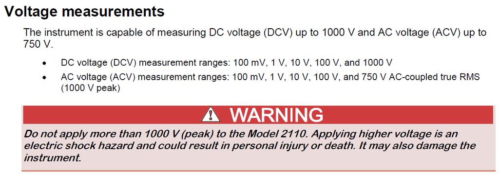
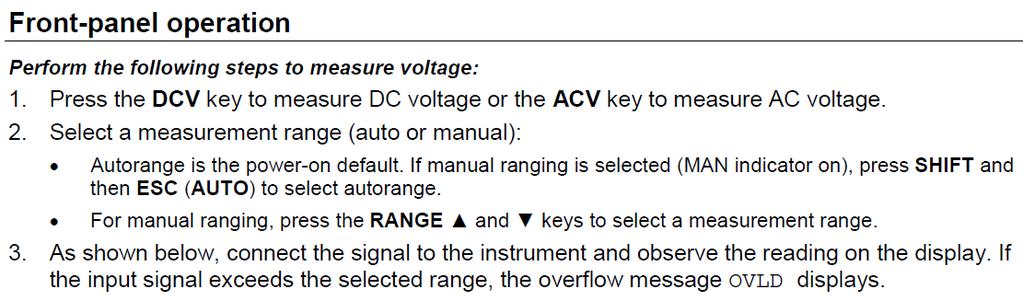
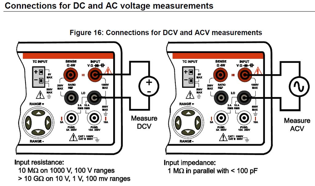
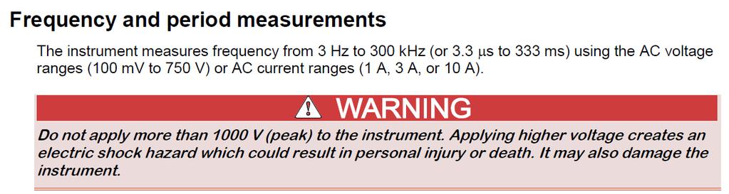
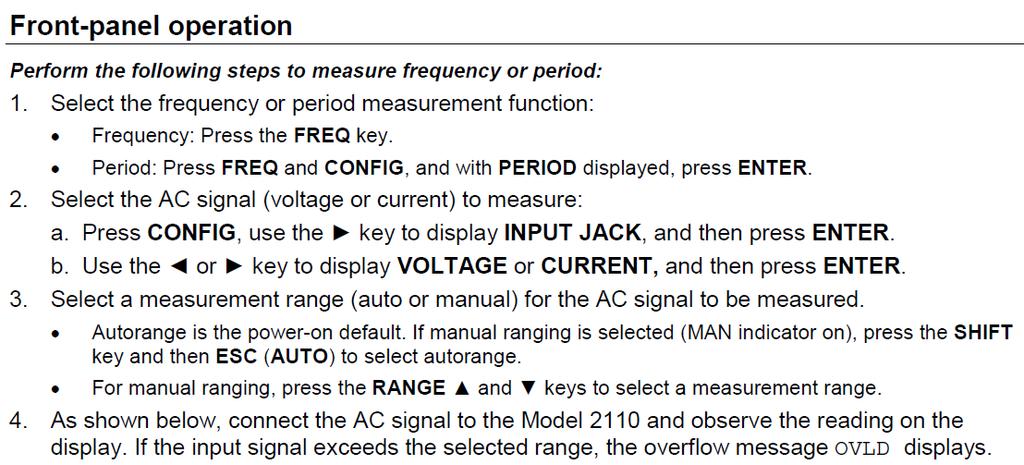
2 Note: Your negligence in following the safety guidelines anytime during the semester will not be tolerated and you would be dropped from the class. 3.2 EQUIPMENT USE: Keithley-DMM ½ Digit Multimeter Figure 1 Front Panel of Keithley-DMM ½ Digit Multimeter 1. Display 2. Power Key 3. Function and operation keys 4. RANGE and scroll keys 5. TC input 6. Terminal and fuses Connections for different measurements as follows: DEPARTMENT OF ELECTRICAL AND COMPUTER ENGINEERING 2
3 DEPARTMENT OF ELECTRICAL AND COMPUTER ENGINEERING 3

4 DEPARTMENT OF ELECTRICAL AND COMPUTER ENGINEERING 4

5 DEPARTMENT OF ELECTRICAL AND COMPUTER ENGINEERING 5
6 DEPARTMENT OF ELECTRICAL AND COMPUTER ENGINEERING 6
7 DEPARTMENT OF ELECTRICAL AND COMPUTER ENGINEERING 7
8 3.2.2 DC Power Supply HY3000 Series Figure 2 Front Panel of DC Power Supply HY3000 Series DEPARTMENT OF ELECTRICAL AND COMPUTER ENGINEERING 8


9 DEPARTMENT OF ELECTRICAL AND COMPUTER ENGINEERING 9
10 DEPARTMENT OF ELECTRICAL AND COMPUTER ENGINEERING 10


11 3.2.3 GW Instek Arbitrary Function Generator AFG-2225 Figure 3 Front Panel of GW Instek AFG-2225 DEPARTMENT OF ELECTRICAL AND COMPUTER ENGINEERING 11

12 DEPARTMENT OF ELECTRICAL AND COMPUTER ENGINEERING 12


13 DEPARTMENT OF ELECTRICAL AND COMPUTER ENGINEERING 13


14 DEPARTMENT OF ELECTRICAL AND COMPUTER ENGINEERING 14

15 DEPARTMENT OF ELECTRICAL AND COMPUTER ENGINEERING 15

16 DEPARTMENT OF ELECTRICAL AND COMPUTER ENGINEERING 16


17 3.2.4 Tektronix MSO2000 Series Oscilloscope DEPARTMENT OF ELECTRICAL AND COMPUTER ENGINEERING 17
18 DEPARTMENT OF ELECTRICAL AND COMPUTER ENGINEERING 18


19 DEPARTMENT OF ELECTRICAL AND COMPUTER ENGINEERING 19
20 And MORE!! DEPARTMENT OF ELECTRICAL AND COMPUTER ENGINEERING 20

21 DEPARTMENT OF ELECTRICAL AND COMPUTER ENGINEERING 21

22 DEPARTMENT OF ELECTRICAL AND COMPUTER ENGINEERING 22
23 DEPARTMENT OF ELECTRICAL AND COMPUTER ENGINEERING 23
24 3.2.5 Tektronix TDS2000C Series Oscilloscope DEPARTMENT OF ELECTRICAL AND COMPUTER ENGINEERING 24
25 DEPARTMENT OF ELECTRICAL AND COMPUTER ENGINEERING 25
26 DEPARTMENT OF ELECTRICAL AND COMPUTER ENGINEERING 26
27 4. LAB DELIVERIES PRELAB: 1. Read the lab equipment tutorial above. LAB EXPERIMENTS: 1. DC Power Supply Setup with Multimeter a) For the power supply, turn both Current and Voltage knobs of Channel fully counter clockwise. b) Turn on the power supply, and the multimeter. c) Use black wire/cable to connect the - port of power supply CH1 to the com on the multimeter, and use red wire/cable to connect the + end of power supply CH1 to the V input of the multimeter. Observe and write down the readings of both power supply CH1 (0A, 0.5V) and multimeter (-0.5V). d) Slowly turn, clockwise, the Current knob of CH1 on power supply, until C.C LED turns off, and C.V LED goes on. Observe the readings of both power supply CH1 (0A, 0V) and multimeter (31mV). e) Slowly turn, clockwise, the Voltage knob of CH1 on power supply, and see if readings on power supply CH1 and multimeter are the same. Continue doing so, SLOWLY, until the Voltage reading stop increasing. Write down the maximum voltage reading (30.6V). f) Based on the process above, think of a way to demonstrate a -10V on multimeter to TA. Hint: Voltage between A and B can be calculated as V AB = V A V B. When you finish using the power supply, go to step a) and turn off the power 2. DC Power Supply Setup with Oscilloscope a) Turn on oscilloscope and press Autoset. Perform the self-detection of both coax measurement probe and oscilloscope. Adjust probe for capacity compensation if necessary. b) Connect the coax measurement probe from Channel 1 to the output of the power supply. Connect the hook of coax probe to the positive output of the power, and the clipper of the coax probe to the negative output of the power. c) Repeat step a) in Experiment 1 and then turn on the power supply. d) Slowly adjust the power supply voltage from 0V to 10V. Observe the changes on the oscilloscope. Press Autoset when necessary (e.g. trace goes off the grid or unstable) e) Press the yellow button of CH1. Change Coupling-DC to AC, and see what happens. DEPARTMENT OF ELECTRICAL AND COMPUTER ENGINEERING 27
28 (TBE-B311 MSO2014B): f) Press Probe Setup, and toggle between Set to 1X and Set to 10X. See what happens. (Vertical grid 5V 500mV) (TBE-B350 TDS2014): f) In Probe, toggle between 1X and 10X. See what happens. (Vertical grid 5V 500mV) g) Turn the Vertical-Scale and Vertical-Position knob of CH1, clockwise or counter clockwise, and see what happens (Vertical grid scales). h) Turn the Horizontal-Scale and Horizontal -Position knob of CH1, clockwise or counter clockwise, and see what happens (Horizontal grid scales). 3. Signal Generator Setup with Oscilloscope a) Initially set up the signal generator with the following parameters (be sure the CH1 Coupling is DC and do not change the other oscilloscope settings) and measure the output with Oscilloscope. Frequency: 1kHz Amplitude: 1V Offset: 0V b) Change the signal generator output to the following, and observe the waveform on the Oscilloscope. Frequency: 2kHz Amplitude: 0.5V Offset: 1V c) Change the Oscilloscope to AC coupling, and observe the results. d) (300/400 level labs) Go back to DC coupling. Change the signal generator to a square waveform (freq. 1MHz, ampl. 1V, offset 0V, duty 75%). Measure the rising (23ns) and falling time (23ns) by using following methods. Built-in function in the measure menu. (You can also try other built-in measurement, e.g. freq. falling time, period, but require appropriate setup of waveform) Use multipurpose cursors to manually measure the rising and falling time, period, etc. e) (300/400 level labs) Press Autoset to reset the Oscope image. Press Trigger-Menu and change rising edge in Slop to falling edge. What changes? POSTLAB REPORT: Include the following elements in the report document: Section Element Theory of operation 1 Include a brief description of every element and phenomenon that appear during the experiments. Prelab report 2 1. Read the label on the coax measurement cable (200MHz, 10MΩ/<12pF, 10X, 300V CAT II). What do they mean? 3 Results of the experiments Experiments Experiment Results 1 Photos of experiment results. DEPARTMENT OF ELECTRICAL AND COMPUTER ENGINEERING 28
29 Photos of experiment results. 3 Photos of experiment results. Answer the questions Questions Question Explain the measurement you got in Experiment 3. Why are the result 1 same/close/different? 2 Explain the observations in Experiment 2(e) What does waveform look like when measure rising/falling time, period, 3 freq, etc. with Oscope s built-in functions, respectively? In other words, explain appropriate in Experiment 3, step d) b uilt-in function part. Conclusions Write down your conclusions, things learned, problems encountered during the lab and how they were solved, etc. Images Paste images (e.g. scratches, drafts, screenshots, photos, etc.) in Postlab report document (only.docx,.doc or.pdf format is accepted). If the sizes of images are too large, convert them to jpg/jpeg format first, and then paste them in the document. Attachments (If needed) Zip your projects. Send through WebCampus as attachments, or provide link to the zip file on Google Drive / Dropbox, etc. 5. REFERENCES & ACKNOWLEDGEMENT 1. User manuals of related equipment 2. Previous EE lab instructions I appreciate the help from faculty members and TAs during the composing of this instruction manual. I would also thank students who provide valuable feedback so that we can offer better high education to the students. DEPARTMENT OF ELECTRICAL AND COMPUTER ENGINEERING 29
CPE 310L EMBEDDED SYSTEM DESIGN LABORATORY
 CPE 310L EMBEDDED SYSTEM DESIGN LABORATORY LABORATORY 1 LAB SAFETY & LAB EQUIPMENT USE TUTORIAL DEPARTMENT OF ELECTRICAL AND COMPUTER ENGINEERING UNIVERSITY OF NEVADA, LAS VEGAS GOALS: Introduce laboratory
CPE 100L DIGITAL LOGIC DESIGN I DESIGN LABORATORY LABORATORY 1 LAB SAFETY QUIZ & LAB EQUIPMENT USE TUTORIAL UNIVERSITY OF NEVADA, LAS VEGAS GOALS:
 CPE 100L DESIGN LABORATORY LABORATORY 1 LAB SAFETY QUIZ & LAB EQUIPMENT USE TUTORIAL DEPARTMENT OF ELECTRICAL AND COMPUTER ENGINEERING UNIVERSITY OF NEVADA, LAS VEGAS GOALS: Introduce laboratory safety
EE 221 L CIRCUIT II. by Ming Zhu
 EE 221 L CIRCUIT II LABORATORY 6: OP AMP CIRCUITS by Ming Zhu DEPARTMENT OF ELECTRICAL AND COMPUTER ENGINEERING UNIVERSITY OF NEVADA, LAS VEGAS OBJECTIVE Learn to use Op Amp to implement simple linear
EE 221 L CIRCUIT II. Learn to use LTspice to run circuit simulations for voltage, current, etc.
 EE 221 L CIRCUIT II LABORATORY 3: LTSPICE DEPARTMENT OF ELECTRICAL AND COMPUTER ENGINEERING UNIVERSITY OF NEVADA, LAS VEGAS OBJECTIVE Learn to use LTspice to run circuit simulations for voltage, current,
EE 221 L CIRCUIT II. by Ming Zhu
 EE 22 L CIRCUIT II LABORATORY 9: RC CIRCUITS, FREQUENCY RESPONSE & FILTER DESIGNS by Ming Zhu DEPARTMENT OF ELECTRICAL AND COMPUTER ENGINEERING UNIVERSITY OF NEVADA, LAS VEGAS OBJECTIVE Enhance the knowledge
EE 221 L CIRCUIT II LABORATORY 4: AC CIRCUITS, CAPACITORS AND INDUCTORS UNIVERSITY OF NEVADA, LAS VEGAS OBJECTIVE COMPONENTS & EQUIPMENT BACKGROUND
 EE 221 L CIRCUIT II LABORATORY 4: AC CIRCUITS, CAPACITORS AND INDUCTORS DEPARTMENT OF ELECTRICAL AND COMPUTER ENGINEERING UNIVERSITY OF NEVADA, LAS VEGAS OBJECTIVE Compare the difference between DC and
EE 320 L LABORATORY 9: MOSFET TRANSISTOR CHARACTERIZATIONS. by Ming Zhu UNIVERSITY OF NEVADA, LAS VEGAS 1. OBJECTIVE 2. COMPONENTS & EQUIPMENT
 EE 320 L ELECTRONICS I LABORATORY 9: MOSFET TRANSISTOR CHARACTERIZATIONS by Ming Zhu DEPARTMENT OF ELECTRICAL AND COMPUTER ENGINEERING UNIVERSITY OF NEVADA, LAS VEGAS 1. OBJECTIVE Get familiar with MOSFETs,
Laboratory Equipment Instruction Manual 2011
 University of Toronto Department of Electrical and Computer Engineering Instrumentation Laboratory GB341 Laboratory Equipment Instruction Manual 2011 Page 1. Wires and Cables A-2 2. Protoboard A-3 3. DC
Introduction to basic laboratory instruments
 BEE 233 Laboratory-1 Introduction to basic laboratory instruments 1. Objectives To learn safety procedures in the laboratory. To learn how to use basic laboratory instruments: power supply, function generator,
Experiment 1.A. Working with Lab Equipment. ECEN 2270 Electronics Design Laboratory 1
 .A Working with Lab Equipment Electronics Design Laboratory 1 1.A.0 1.A.1 3 1.A.4 Procedures Turn in your Pre Lab before doing anything else Setup the lab waveform generator to output desired test waveforms,
EECS 318 Electronics Lab Laboratory #2 Electronic Test Equipment
 EECS 318 Electronics Lab Laboratory #2 Electronic Test Equipment Objectives: The purpose of this laboratory is to acquaint you with the electronic sources and measuring equipment you will be using throughout
Introduction to basic laboratory instruments
 Introduction to basic laboratory instruments 1. OBJECTIVES... 2 2. LABORATORY SAFETY... 2 3. BASIC LABORATORY INSTRUMENTS... 2 4. USING A DC POWER SUPPLY... 2 5. USING A FUNCTION GENERATOR... 3 5.1 TURN
Sept 13 Pre-lab due Sept 12; Lab memo due Sept 19 at the START of lab time, 1:10pm
 Sept 13 Pre-lab due Sept 12; Lab memo due Sept 19 at the START of lab time, 1:10pm EGR 220: Engineering Circuit Theory Lab 1: Introduction to Laboratory Equipment Pre-lab Read through the entire lab handout
Lab 0: Introduction to basic laboratory instruments. Revised by Dan Hoang & Tai-Chang Chen 03/30/2009
 Lab 0: Introduction to basic laboratory instruments Revised by Dan Hoang & Tai-Chang Chen 03/30/2009 1. Objectives 1. To learn safety procedures in the laboratory. 2. To learn how to use basic laboratory
Introduction to Basic Laboratory Instruments
 Introduction to Contents: 1. Objectives... 2 2. Laboratory Safety... 2 3.... 2 4. Using a DC Power Supply... 2 5. Using a Function Generator... 3 5.1 Turn on the Instrument... 3 5.2 Setting Signal Type...
Lab 6 Instrument Familiarization
 Lab 6 Instrument Familiarization What You Need To Know: Voltages and currents in an electronic circuit as in a CD player, mobile phone or TV set vary in time. Throughout todays lab you will investigate
Inverting_Amplifier -- Overview
 Inverting_Amplifier -- Overview Inverting Amplifier Objectives: After performing this lab exercise, learner will be able to: Understand and comprehend working of opamp Design & build inverting amplifier
Equipment: You will use the bench power supply, function generator and oscilloscope.
 EE203 Lab #0 Laboratory Equipment and Measurement Techniques Purpose Your objective in this lab is to gain familiarity with the properties and effective use of the lab power supply, function generator
Non_Inverting_Voltage_Follower -- Overview
 Non_Inverting_Voltage_Follower -- Overview Non-Inverting, Unity-Gain Amplifier Objectives: After performing this lab exercise, learner will be able to: Understand and comprehend working of opamp Design
Faculty of Engineering, Thammasat University
 Faculty of Engineering, Thammasat University Experiment 6: Oscilloscope (For room 506) Objectives: 1. To familiarize you with the Oscilloscope and Function Generator User Manual: Oscilloscope 1 5 9 4 7
Introduction to Oscilloscopes Instructor s Guide
 Introduction to Oscilloscopes A collection of lab exercises to introduce you to the basic controls of a digital oscilloscope in order to make common electronic measurements. Revision 1.0 Page 1 of 25 Copyright
ECE65 Introduction to the Function Generator and the Oscilloscope Created by: Eldridge Alcantara (Spring 2007)
") ECE65 Introduction to the Function Generator and the Oscilloscope Created by: Eldridge Alcantara (Spring 2007) I. Getting Started with the Function Generator OUTPUT Red Clip Small Black Clip 1) Turn on
ECE65 Introduction to the Function Generator and the Oscilloscope Created by: Eldridge Alcantara (Spring 2007) I. Getting Started with the Function Generator OUTPUT Red Clip Small Black Clip 1) Turn on
EE 210: CIRCUITS AND DEVICES
 EE 210: CIRCUITS AND DEVICES LAB #3: VOLTAGE AND CURRENT MEASUREMENTS This lab features a tutorial on the instrumentation that you will be using throughout the semester. More specifically, you will see
CPE 100L LOGIC DESIGN I
 CPE 100L LABORATORY 3: COMBINATIONAL CIRCUIT DESIGN FULL ADDER BY GRZEGORZ CHMAJ DEPARTMENT OF ELECTRICAL AND COMPUTER ENGINEERING UNIVERSITY OF NEVADA, LAS VEGAS GOALS: Develop the ability to write a
EENG-201 Experiment # 4: Function Generator, Oscilloscope
 EENG-201 Experiment # 4: Function Generator, Oscilloscope I. Objectives Upon completion of this experiment, the student should be able to 1. To become familiar with the use of a function generator. 2.
EXPERIMENT 2 DIGITAL STORAGE OSCILLOSCOPE
 EXPERIMENT 2 DIGITAL STORAGE OSCILLOSCOPE 2.1 Objective: In this experiment, you will learn the basic usage of digital storage oscilloscope (DSO) of GW Instek Technologies. More specifically you will learn,
ME 365 EXPERIMENT 1 FAMILIARIZATION WITH COMMONLY USED INSTRUMENTATION
 Objectives: ME 365 EXPERIMENT 1 FAMILIARIZATION WITH COMMONLY USED INSTRUMENTATION The primary goal of this laboratory is to study the operation and limitations of several commonly used pieces of instrumentation:
Ph 3455 The Franck-Hertz Experiment
 Ph 3455 The Franck-Hertz Experiment Required background reading Tipler, Llewellyn, section 4-5 Prelab Questions 1. In this experiment, we will be using neon rather than mercury as described in the textbook.
The Oscilloscope. Vision is the art of seeing things invisible. J. Swift ( ) OBJECTIVE To learn to operate a digital oscilloscope.
 OBJECTIVE To learn to operate a digital oscilloscope.") The Oscilloscope Vision is the art of seeing things invisible. J. Swift (1667-1745) OBJECTIVE To learn to operate a digital oscilloscope. THEORY The oscilloscope, or scope for short, is a device for drawing
The Oscilloscope Vision is the art of seeing things invisible. J. Swift (1667-1745) OBJECTIVE To learn to operate a digital oscilloscope. THEORY The oscilloscope, or scope for short, is a device for drawing
LAB 1: Familiarity with Laboratory Equipment (_/10)
") LAB 1: Familiarity with Laboratory Equipment (_/10) PURPOSE o gain familiarity with basic laboratory equipment oscilloscope, oscillator, multimeter and electronic components. EQUIPMEN (i) Oscilloscope
LAB 1: Familiarity with Laboratory Equipment (_/10) PURPOSE o gain familiarity with basic laboratory equipment oscilloscope, oscillator, multimeter and electronic components. EQUIPMEN (i) Oscilloscope
University of California, San Diego Department of Electrical and Computer Engineering
 University of California, San Diego Department of Electrical and Computer Engineering Part One: Introduction of Lab TAs ECE65, Spring 2007 Lab 0, ECE 65 Lab Orientation 1) James Liao, geniojames@yahoo.com
Experiment #2: Introduction to Lab Equipment: Function Generator, Oscilloscope, and Multisim
 SCHOOL OF ENGINEERING AND APPLIED SCIENCE DEPARTMENT OF ELECTRICAL AND COMPUTER ENGINEERING ECE 2110: CIRCUIT THEORY LABORATORY Experiment #2: Introduction to Lab Equipment: Function Generator, Oscilloscope,
EE 3302 LAB 1 EQIUPMENT ORIENTATION
 EE 3302 LAB 1 EQIUPMENT ORIENTATION Pre Lab: Calculate the theoretical gain of the 4 th order Butterworth filter (using the formula provided. Record your answers in Table 1 before you come to class. Introduction:
LABORATORY 4. Palomar College ENGR210 Spring 2017 ASSIGNED: 3/21/17
 LABORATORY 4 ASSIGNED: 3/21/17 OBJECTIVE: The purpose of this lab is to evaluate the transient and steady-state circuit response of first order and second order circuits. MINIMUM EQUIPMENT LIST: You will
UNIVERSITY OF CALIFORNIA, SANTA BARBARA Department of Electrical and Computer Engineering. ECE 2A & 2B Laboratory Equipment Information
 UNIVERSITY OF CALIFORNIA, SANTA BARBARA Department of Electrical and Computer Engineering ECE 2A & 2B Laboratory Equipment Information Table of Contents Digital Multi-Meter (DMM)... 1 Features... 1 Using
ENGR 1110: Introduction to Engineering Lab 7 Pulse Width Modulation (PWM)
") ENGR 1110: Introduction to Engineering Lab 7 Pulse Width Modulation (PWM) Supplies Needed Motor control board, Transmitter (with good batteries), Receiver Equipment Used Oscilloscope, Function Generator,
ENGR 1110: Introduction to Engineering Lab 7 Pulse Width Modulation (PWM) Supplies Needed Motor control board, Transmitter (with good batteries), Receiver Equipment Used Oscilloscope, Function Generator,
Agilent 33220A Function Generator Tutorial
 Contents UNIVERSITY OF CALIFORNIA AT BERKELEY College of Engineering Department of Electrical Engineering and Computer Sciences EE105 Lab Experiments Agilent 33220A Function Generator Tutorial 1 Introduction
Agilent 33522A Function Arbitrary Waveform Generator. Tektronix TDS 3012B Oscilloscope
 Agilent 33522A Function/Arbitrary Waveform Generator and Tektronix TDS 3012B Oscilloscope Agilent 33522A Function Arbitrary Waveform Generator The signal source for this lab is the Agilent 33522A Function
CHAPTER 6. Motor Driver
 CHAPTER 6 Motor Driver In this lab, we will construct the circuitry that your robot uses to drive its motors. However, before testing the motor circuit we will begin by making sure that you are able to
EC310 Security Exercise 20
 EC310 Security Exercise 20 Introduction to Sinusoidal Signals This lab demonstrates a sinusoidal signal as described in class. In this lab you will identify the different waveform parameters for a pure
Experiment 9 The Oscilloscope and Function Generator
 Experiment 9 The Oscilloscope and Function Generator Introduction The oscilloscope is one of the most important electronic instruments available for making circuit measurements. It displays a curve plot
ECE 53A: Fundamentals of Electrical Engineering I
 ECE 53A: Fundamentals of Electrical Engineering I Laboratory Assignment #1: Instrument Operation, Basic Resistor Measurements and Kirchhoff s Laws Fall 2007 General Guidelines: - Record data and observations
Lab Reference Manual. ECEN 326 Electronic Circuits. Texas A&M University Department of Electrical and Computer Engineering
 Lab Reference Manual ECEN 326 Electronic Circuits Texas A&M University Department of Electrical and Computer Engineering Contents 1. Circuit Analysis in PSpice 3 1.1 Transient and DC Analysis 3 1.2 Measuring
University of Jordan School of Engineering Electrical Engineering Department. EE 204 Electrical Engineering Lab
 University of Jordan School of Engineering Electrical Engineering Department EE 204 Electrical Engineering Lab EXPERIMENT 1 MEASUREMENT DEVICES Prepared by: Prof. Mohammed Hawa EXPERIMENT 1 MEASUREMENT
EE 201 Function / Arbitrary Waveform Generator and Oscilloscope Tutorial
 EE 201 Function / Arbitrary Waveform Generator and Oscilloscope Tutorial 1 This is a programmed learning instruction manual. It is written for the Agilent DSO3202A Digital Storage Oscilloscope. The prerequisite
Name EET 1131 Lab #2 Oscilloscope and Multisim
 Name EET 1131 Lab #2 Oscilloscope and Multisim Section 1. Oscilloscope Introduction Equipment and Components Safety glasses Logic probe ETS-7000 Digital-Analog Training System Fluke 45 Digital Multimeter
PHYSICS 171 UNIVERSITY PHYSICS LAB II. Experiment 4. Alternating Current Measurement
 PHYSICS 171 UNIVERSITY PHYSICS LAB II Experiment 4 Alternating Current Measurement Equipment: Supplies: Oscilloscope, Function Generator. Filament Transformer. A sine wave A.C. signal has three basic properties:
Introduction to oscilloscope. and time dependent circuits
 Physics 9 Intro to oscilloscope, v.1.0 p. 1 NAME: SECTION DAY/TIME: TA: LAB PARTNER: Introduction to oscilloscope and time dependent circuits Introduction In this lab, you ll learn the basics of how to
Notes on Experiment #1
 Notes on Experiment #1 Bring graph paper (cm cm is best) From this week on, be sure to print a copy of each experiment and bring it with you to lab. There will not be any experiment copies available in
Tektronix Courseware. Academic Labs. Sample Labs from Popular Electrical and Electronics Engineering Curriculum
 Tektronix Courseware Academic Labs Sample Labs from Popular Electrical and Electronics Engineering Curriculum March 3, 2014 HalfWaveRectifier -- Overview OBJECTIVES After performing this lab exercise,
Introduction to Electronic Equipment
 Introduction to Electronic Equipment INTRODUCTION This semester you will be exploring electricity and magnetism. In order to make your time in here more instructive we ve designed this laboratory exercise
EGRE 101 DC Motor II
 EGRE 101 DC Motor II Preamble In this week s laboratory exercise you will become familiar with: Converting a circuit schematic to a physical circuit implementation Measuring physical quantities relevant
Physics 323. Experiment # 1 - Oscilloscope and Breadboard
 Physics 323 Experiment # 1 - Oscilloscope and Breadboard Introduction In order to familiarise yourself with the laboratory equipment, a few simple experiments are to be performed. References: XYZ s of
Lab #1 Lab Introduction
 Cir cuit s 212 Lab Lab #1 Lab Introduction Special Information for this Lab s Report Because this is a one-week lab, please hand in your lab report for this lab at the beginning of next week s lab. The
Introduction to Lab Instruments
 ECE316, Experiment 00, 2017 Communications Lab, University of Toronto Introduction to Lab Instruments Bruno Korst - bkf@comm.utoronto.ca Abstract This experiment will review the use of three lab instruments
LAB I. INTRODUCTION TO LAB EQUIPMENT
 1. OBJECTIVE LAB I. INTRODUCTION TO LAB EQUIPMENT In this lab you will learn how to properly operate the oscilloscope Agilent MSO6032A, the Keithley Source Measure Unit (SMU) 2430, the function generator
Combinational logic: Breadboard adders
 ! ENEE 245: Digital Circuits & Systems Lab Lab 1 Combinational logic: Breadboard adders ENEE 245: Digital Circuits and Systems Laboratory Lab 1 Objectives The objectives of this laboratory are the following:
The University of Jordan Mechatronics Engineering Department Electronics Lab.( ) Experiment 1: Lab Equipment Familiarization
 Experiment 1: Lab Equipment Familiarization") The University of Jordan Mechatronics Engineering Department Electronics Lab.(0908322) Experiment 1: Lab Equipment Familiarization Objectives To be familiar with the main blocks of the oscilloscope and
The University of Jordan Mechatronics Engineering Department Electronics Lab.(0908322) Experiment 1: Lab Equipment Familiarization Objectives To be familiar with the main blocks of the oscilloscope and
Low_Pass_Filter_1st_Order -- Overview
 Low_Pass_Filter_1st_Order -- Overview 1 st Order Low Pass Filter Objectives: After performing this lab exercise, learner will be able to: Understand and comprehend working of opamp Comprehend basics of
Experiment # 1 Introduction to Lab Equipment
 Experiment # 1 Introduction to Lab Equipment 1. Synopsis: In this introductory lab, we will review the basic concepts of digital logic design and learn how to use the equipment available in the laboratory.
EE EXPERIMENT 1 (2 DAYS) BASIC OSCILLOSCOPE OPERATIONS INTRODUCTION DAY 1
 BASIC OSCILLOSCOPE OPERATIONS INTRODUCTION DAY 1") EE 2101 - EXPERIMENT 1 (2 DAYS) BASIC OSCILLOSCOPE OPERATIONS INTRODUCTION The oscilloscope is the most versatile and most important tool in this lab and is probably the best tool an electrical engineer
EE 2101 - EXPERIMENT 1 (2 DAYS) BASIC OSCILLOSCOPE OPERATIONS INTRODUCTION The oscilloscope is the most versatile and most important tool in this lab and is probably the best tool an electrical engineer
LAB I. INTRODUCTION TO LAB EQUIPMENT
 LAB I. INTRODUCTION TO LAB EQUIPMENT 1. OBJECTIVE In this lab you will learn how to properly operate the basic bench equipment used for characterizing active devices: 1. Oscilloscope (Keysight DSOX 1102A),
Frequency and Time Domain Representation of Sinusoidal Signals
 Frequency and Time Domain Representation of Sinusoidal Signals By: Larry Dunleavy Wireless and Microwave Instruments University of South Florida Objectives 1. To review representations of sinusoidal signals
ECE 2274 Lab 1 (Intro)
") ECE 2274 Lab 1 (Intro) Richard Dumene: Spring 2018 Revised: Richard Cooper: Spring 2018 Forward (DO NOT TURN IN) The purpose of this lab course is to familiarize you with high-end lab equipment, and train
ECE 2274 Lab 1 (Intro) Richard Dumene: Spring 2018 Revised: Richard Cooper: Spring 2018 Forward (DO NOT TURN IN) The purpose of this lab course is to familiarize you with high-end lab equipment, and train
UNIVERSITY OF CALIFORNIA, DAVIS Department of Electrical and Computer Engineering. EEC 180A DIGITAL SYSTEMS I Winter 2015
 UNIVERSITY OF CALIFORNIA, DAVIS Department of Electrical and Computer Engineering EEC 180A DIGITAL SYSTEMS I Winter 2015 LAB 2: INTRODUCTION TO LAB INSTRUMENTS The purpose of this lab is to introduce the
Exercise 1: AC Waveform Generator Familiarization
 Exercise 1: AC Waveform Generator Familiarization EXERCISE OBJECTIVE When you have completed this exercise, you will be able to operate an ac waveform generator by using equipment provided. You will verify
Step Response of RC Circuits
 EE 233 Laboratory-1 Step Response of RC Circuits 1 Objectives Measure the internal resistance of a signal source (eg an arbitrary waveform generator) Measure the output waveform of simple RC circuits excited
Tektronix digital oscilloscope, BK Precision Function Generator, coaxial cables, breadboard, the crystal earpiece from your AM radio kit.
 Experiment 0: Review I. References The 174 and 275 Lab Manuals Any standard text on error analysis (for example, Introduction to Error Analysis, J. Taylor, University Science Books, 1997) The manual for
Function Generator Guide Tektronix AFG3102
 Tektronix AFG3102 ersion 2008-Jan-1 Dept. of Electrical & Computer Engineering Portland State University Copyright 2008 Portland State University 1 Basic Information This guide provides basic instructions
Lab 3: RC Circuits. Construct circuit 2 in EveryCircuit. Set values for the capacitor and resistor to match those in figure 2 and set the frequency to
 Lab 3: RC Circuits Prelab Deriving equations for the output voltage of the voltage dividers you constructed in lab 2 was fairly simple. Now we want to derive an equation for the output voltage of a circuit
EE 210 Lab Exercise #3 Introduction to PSPICE
 EE 210 Lab Exercise #3 Introduction to PSPICE Appending 4 in your Textbook contains a short tutorial on PSPICE. Additional information, tutorials and a demo version of PSPICE can be found at the manufacturer
3.003 Lab 3 Part A. Measurement of Speed of Light
 3.003 Lab 3 Part A. Measurement of Speed of Light Objective: To measure the speed of light in free space Experimental Apparatus: Feb. 18, 2010 Due Mar. 2, 2010 Components: 1 Laser, 4 mirrors, 1 beam splitter
MASSACHUSETTS INSTITUTE OF TECHNOLOGY
 Name: MASSACHUSETTS INSTITUTE OF TECHNOLOGY 6.091 Hands-On Introduction to EE Lab Skills Laboratory No. 1 Oscilloscopes, Multimeter, Function Generator IAP 2008 1 Objective In this laboratory, you will
EECE208 INTRO To ELECTRICAL ENG LAB. LAB 2. Instrumentation
 EECE208 INTRO To ELECTRICAL ENG LAB Dr. Charles Kim LAB 2. Instrumentation Objectives A brief description of the equipment (Oscilloscope, Function Generator, Power Supply, and Digital Multimeter) and its
ECE 2274 Lab 2. Your calculator will have a setting that will automatically generate the correct format.
 ECE 2274 Lab 2 Forward (DO NOT TURN IN) You are expected to use engineering exponents for all answers (p,n,µ,m, N/A, k, M, G) and to give each with a precision between one and three leading digits and
ENGR 210 Lab 6 Use of the Function Generator & Oscilloscope
 ENGR 210 Lab 6 Use of the Function Generator & Oscilloscope In this laboratory you will learn to use two additional instruments in the laboratory, namely the function/arbitrary waveform generator, which
MAE106 Laboratory Exercises Lab # 1 - Laboratory tools
 MAE106 Laboratory Exercises Lab # 1 - Laboratory tools University of California, Irvine Department of Mechanical and Aerospace Engineering Goals To learn how to use the oscilloscope, function generator,
Oscilloscope and Function Generators
 MEHRAN UNIVERSITY OF ENGINEERING AND TECHNOLOGY, JAMSHORO DEPARTMENT OF ELECTRONIC ENGINEERING ELECTRONIC WORKSHOP # 02 Oscilloscope and Function Generators Roll. No: Checked by: Date: Grade: Object: To
Supplement. TDS5032 and TDS5034 Digital Phosphor Oscilloscopes
 TDS5032 and TDS5034 Digital Phosphor Oscilloscopes 071-1316-00 www.tektronix.com 071131600 Copyright Tektronix, Inc. All rights reserved. Tektronix products are covered by U.S. and foreign patents, issued
Sallen-Key_High_Pass_Filter -- Overview
 Sallen-Key_High_Pass_Filter -- Overview Sallen-Key High Pass Filter Objectives: After performing this lab exercise, learner will be able to: Understand & analyze working of Sallen-Key topology of active
332:223 Principles of Electrical Engineering I Laboratory Experiment #2 Title: Function Generators and Oscilloscopes Suggested Equipment:
 RUTGERS UNIVERSITY The State University of New Jersey School of Engineering Department Of Electrical and Computer Engineering 332:223 Principles of Electrical Engineering I Laboratory Experiment #2 Title:
Digital Debug With Oscilloscopes Lab Experiment
 Digital Debug With Oscilloscopes A collection of lab exercises to introduce you to digital debugging techniques with a digital oscilloscope. Revision 1.0 Page 1 of 23 Revision 1.0 Page 2 of 23 Copyright
Oscilloscope Operation. Visualizing Signals and Making Measurements
 Oscilloscope Operation Visualizing Signals and Making Measurements Set Up Oscilloscope Start with the oscilloscope off, with the input plugged into channel one. Press the power button to turn the scope
Exercise 2: FM Detection With a PLL
 Phase-Locked Loop Analog Communications Exercise 2: FM Detection With a PLL EXERCISE OBJECTIVE When you have completed this exercise, you will be able to explain how the phase detector s input frequencies
electrical noise and interference, environmental changes, instrument resolution, or uncertainties in the measurement process itself.
 MUST 382 / EELE 491 Spring 2014 Basic Lab Equipment and Measurements Electrical laboratory work depends upon various devices to supply power to a circuit, to generate controlled input signals, and for
MEMORIAL UNIVERSITY OF NEWFOUNDLAND. Faculty of Engineering and Applied Science. Laboratory Manual for. Eng Circuit Analysis (2011)
") MEMORIAL UNIVERSITY OF NEWFOUNDLAND Faculty of Engineering and Applied Science Laboratory Manual for Eng. 3821 Circuit Analysis (2011) Instructor: E. Gill PREFACE The laboratory exercises in this manual
MEMORIAL UNIVERSITY OF NEWFOUNDLAND Faculty of Engineering and Applied Science Laboratory Manual for Eng. 3821 Circuit Analysis (2011) Instructor: E. Gill PREFACE The laboratory exercises in this manual
User Manual. TDS 420A, TDS 430A, TDS 460A & TDS 510A Digitizing Oscilloscopes
 User Manual TDS 420A, TDS 430A, TDS 460A & TDS 510A Digitizing Oscilloscopes 070-9701-02 Copyright Tektronix, Inc. All rights reserved. Tektronix products are covered by U.S. and foreign patents, issued
Sonoma State University Department of Engineering Science Spring 2017
 EE 110 Introduction to Engineering & Laboratory Experience Saeid Rahimi, Ph.D. Lab 4 Introduction to AC Measurements (I) AC signals, Function Generators and Oscilloscopes Function Generator (AC) Battery
LAB II. INTRODUCTION TO LAB EQUIPMENT
 1. OBJECTIVE LAB II. INTRODUCTION TO LAB EQUIPMENT In this lab you will learn how to properly operate the oscilloscope Keysight DSOX1102A, the Keithley Source Measure Unit (SMU) 2430, the function generator
ECE 480: SENIOR DESIGN LABORATORY
 ECE 480: SENIOR DESIGN LABORATORY DEPARTMENT OF ELECTRICAL AND COMPUTER ENGINEERING MICHIGAN STATE UNIVERSITY I. TITLE: Lab I - Introduction to the Oscilloscope, Function Generator, Digital Multimeter
Electronics Design Laboratory Lecture #1, Fall 2014
 Electronics Design Laboratory Lecture #1, Fall 2014 Dr. Daniel Seltzer Teaching Assistants: Fenglong Lu & Ali Sepahvand Electronics Design Laboratory 1 Daniel Seltzer seltzer@colorado.edu Fenglong Lu Fenglong.Lu@colorado.edu
User Manual. TDS 420A, TDS 430A, TDS 460A & TDS 510A Digitizing Oscilloscopes
 User Manual TDS 420A, TDS 430A, TDS 460A & TDS 510A Digitizing Oscilloscopes 070-9701-03 www.tektronix.com Copyright Tektronix, Inc. All rights reserved. Tektronix products are covered by U.S. and foreign
Intro to Lab Equipment and Procedures
 Dr. Anthony D. Johnson s11l1_dild.fm- 1 Lab Assignment #1 Intro to Lab Equipment and Procedures 1. OBJECTIVES - becoming familiar with the Lab environment, - becoming familiar with the protoboards for
Press Cursors and use the appropriate X and Y functions to measure period and peak-peak voltage of the square wave.
 Equipment Review To assure that everyone is up to speed for the hurdles ahead, the first lab of the semester is traditionally an easy review of electrical laboratory fundamentals. There will, however,
A semester of Experiments for ECE 225
 A semester of Experiments for ECE 225 Contents General Lab Instructions... 3 Notes on Experiment #1... 4 ECE 225 Experiment #1 Introduction to the function generator and the oscilloscope... 5 Notes on
Physics 310 Lab 2 Circuit Transients and Oscilloscopes
 Physics 310 Lab 2 Circuit Transients and Oscilloscopes Equipment: function generator, oscilloscope, two BNC cables, BNC T connector, BNC banana adapter, breadboards, wire packs, some banana cables, three
Name: Resistors and Basic Resistive Circuits. Objective: To gain experience with data acquisition proto-boards physical resistors. Table of Contents:
 Objective: To gain experience with data acquisition proto-boards physical resistors Table of Contents: Name: Resistors and Basic Resistive Circuits Pre-Lab Assignment 1 Background 2 National Instruments
EE 1210 Op Amps, Gain, and Signal Integrity Laboratory Project 6
 Objective Information The purposes of this laboratory project are for the student to observe an inverting operational amplifier circuit, to demonstrate how the resistors in an operational amplifier circuit
Integrators, differentiators, and simple filters
 BEE 233 Laboratory-4 Integrators, differentiators, and simple filters 1. Objectives Analyze and measure characteristics of circuits built with opamps. Design and test circuits with opamps. Plot gain vs.
EE-4022 Experiment 2 Amplitude Modulation (AM)
") EE-4022 MILWAUKEE SCHOOL OF ENGINEERING 2015 Page 2-1 Student objectives: EE-4022 Experiment 2 Amplitude Modulation (AM) In this experiment the student will use laboratory modules to implement operations
EE-4022 MILWAUKEE SCHOOL OF ENGINEERING 2015 Page 2-1 Student objectives: EE-4022 Experiment 2 Amplitude Modulation (AM) In this experiment the student will use laboratory modules to implement operations