Electric Circuit II Lab Manual Session #1
|
|
|
- Stewart Simmons
- 5 years ago
- Views:
Transcription

1 Department of Electrical Engineering Electric Circuit II Lab Manual Session #1 Subject Lecturer Dr. Yasser Hegazy Name: Group:
2 Lab Policies 1. Each lab session lasts 90 min and starts promptly. A brief introduction with demo may be given by the instructor at the beginning of the lab. Everybody has to finish on time, so please time yourself carefully. Doing the pre-lab can save you a lot of time. 2. Preparing the lab is very important; as it will save you time and allow you to work more efficiently. The pre-lab includes reading the lab assignment in advance, answering the questions or doing the calculations, and if necessary reviewing the material in the textbook. All pre-lab preparation must be recorded and dated in the lab notebook prior do doing the lab. The lab instructor will check your pre-lab write-up and sign your notebook. 3. As a part of the lab preparation, you can use Spice to simulate the actual experiments you will be doing in the lab. Spice is available in the PC labs. You can paste the result of the simulations in the notebook. Make sure you label the graphs and tables clearly. If you make the simulation prior to the lab you must bring the print out of the simulated results. 4. Pre-lab Quiz, Each week there is an Oral quiz. This quiz must be taken at the beginning of your lab session. 5. Student partnerships, Each lab is done in groups of two. The team approach encourages interaction and helps with the debugging and data collection. Each student has his/her own lab notebook and is responsible for recording the pre-lab, recording the measurement data. However, lab report has to be handed in individually. 6. Collaboration, Students are working in groups of two in the laboratory. This encourages team work and makes the conduction of the experiments more efficient. You can collaborate on the pre-lab and on interpretation of the measured data. However, each student is responsible for writing the pre-lab and recording the data in his or her notebook. Copying of data from other groups or altered information will result in a zero grade. The lab report is a joined effort and each student should contribute equally to writing the report. 7. Each lab notebook needs to be signed and dated by the instructor or TA before leaving the lab. The instructor will check the pre-lab and notebook entries for the current lab assignment. The students are responsible for securing the signature. 8. Instruments and supplies, The major instruments you will need are permanently installed in the stations. A selection of wires, cables and connectors are inside your kit. Small parts (resistors, capacitors, transistors, ICs) will be available in the bins in the lab area. Capacitors, transistors and integrated circuits (ICs) can be reused and should be left on the table in the same manner as they were obtained. 2
3 9. Leave your workplace at least as clean and tidy as you found it. Put everything back in its proper place. If the workplace is not tidy after you finish it will cause to lose some Marks. Please be sure to Close your PC after you finish of simulations. 10. Grading Policy The lab is 20 Marks divided into 12 for reports & 8 for pre lab quiz. 11. Lab Report and Turn-In Policy The lab report due date is the following lab. Note : No Late Reports are accepted 12. Precautions Electronic test equipment can be damaged if incorrectly used. The function generator will be damaged if a large DC or AC voltage is applied to the outputs. The oscilloscope also has input limitations. Do not exceed 300V on any oscilloscope input. Power supplies can also be damaged if an external voltage in excess of the supply output voltage is fed back into the supply. The most common ways multi-meters are damaged are by trying to measure voltage when the meter is set to measure current or resistance or by exceeding the maximum voltage when in the voltage measurement mode. Think twice before connecting a meter. In particular, check the position of the function switch and ensure the test leads are connected to the proper inputs on the meter. If you make a mistake you could blow the meter s internal fuse or damage the converter chip. Our lab procedures are designed to avoid these problems but you should always be aware of your test equipment s limitations.no foods or drinks are allowed inside the lab for any reason. 13. Material the sessions are uploaded weekly on your Site eee.guc.edu.eg.for Pspice, there is a good tutorial for Pennsylvania University Department of Electrical and Systems Engineering in this link Project there will be a project at the end of the lab sessions to examine your gain knowledge in the lab. Acknowledgement to Eng.Mohamed El Hadidy as his material helped us in preparing these labs. 3

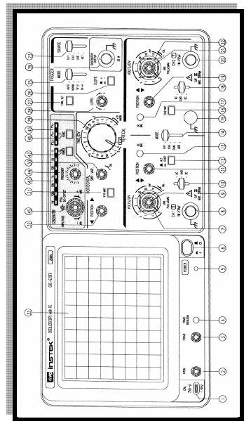
4 Oscilloscope Front Panel 4
5 5
6 CRT: (6) POWER Main power switch of the instrument. Turn on the switch to get the LED (5) lighted. (2).INTEN Control the brightness of the spot or trace. (3) FOCUS Focus the trace to the sharpest image. (4) TRACE ROTATION Semi-fix potentiometer for aligning the horizontal trace in parallel with graticule lines. (33) FILTER The filter is easy for waveform viewing. Vertical Axis: (8) CH1 (X) input The vertical input terminal of CH1 is X-axis in X-Y operation. (20) CH 2 (Y) input The vertical input terminal of CH2 is Y-axis in X-Y operation. (10) & (18) AC-GND-DC Select connection mode between input signal and vertical amplifier. AC AC coupling GND Vertical amplifier input is grounded and input terminals are disconnected. DC DC coupling (7) & (22) VOLTS/DIV Select the vertical axis sensitivity from 5mV/DIV to 5V/DIV with 10 ranges totally. (9) & (21) VARIABLE Fine adjustment of sensitivity with a factor of _1/2.5 of the indicated value. The sensitivity is calibrated to specific value in the CAL position. When this knob is pulled out (x5 MAG state), it will multiply 5 by the amplifier sensitivity. (13) & (17) CH1 & CH2 DC BAL. The knobs are used for adjusting the attenuator balance. See DC BAL adjustments for details. 6
7 (11) & (19)56POSITION Vertical positioning control of trace or spot. (14)VERT MODE: Select operation modes of CH1 and CH2 amplifiers. CH1 Operate the oscilloscope as a single-channel instrument by selecting CH1 alone. CH2 Operate the oscilloscope as a single-channel instrument by selecting CH2 alone. DUAL Operate the oscilloscope as a dual-channel instrument by selecting CH1 and CH2. ADD The oscilloscope displays the algebraic sum (CH1 + CH2) or subtraction (CH1 - CH2). (The subtraction function effects only when push in CH2 INV (16) button). When this switch is released in the dual-trace mode, the channel 1 and channel 2 inputs are alternately displayed (Normally used at faster sweep speeds). When this switch is depressed in the dual-trace mode, the channel 1 and channel 2 inputs are chopped and displayed simultaneously. (Normally used at slower sweep speeds). (16)CH2 INV When press CH2 INV button, it will inverts the CH2 input signal in CH2 and in ADD MODE, the channel 2 trigger signal pickoff is also inverted. Triggering (24) EXT TRIG IN input terminal Input terminal is used for external triggering signal. To use this terminal, set SOURCE (23) to the EXT position. (23) SOURCE Select the internal triggering source signal, and the EXT TRIG IN input signal. CH1 Press key DUAL or ADD of VERT MODE (14), select CH1 to get internal triggering source signal. CH2 Press key DUAL or ADD of VERT MODE (14), select CH2 to get internal triggering source signal. (27) TRIG.ALT Set VERT MODE switch (14) in DUAL or ADD key, select CH1 or CH2 by the SOURCE switch (23), then press TRIG.ALT switch (27), the internal triggering source signal will display alternately from CH1 and CH2. 7
8 LINE Display the triggering signal from AC power line frequency signal. EXT Obtain the external triggering source signal by applying external signal to EXT TRIG IN input terminal (24). (26) SLOPE Triggering slope button. + Triggering occurs when the trigger signal crosses the trigger level by positive-going course. - Triggering occurs when the trigger signal crosses the trigger level by negative-going course. (28) LEVEL Display a synchronized stationary waveform and set a start point for the waveform. Toward + The trigger level moves upward on the display waveform. Toward - The trigger level moves downward on the display waveform. (25) TRIGGER MODE Trigger mode selection. AUTO If no trigger signal applied or the trigger signal frequency is less than 25Hz, the sweep will be in the free run mode. NORM If no trigger signal applied and sweep is in a stand-by state, there will be no trace appear. TV-V Used for observing entire vertical picture of television signal. TV-H Used for observing entire horizontal picture of television signal. (Both TV-V and TV-H synchronize only when the synchronizing signal is negative.) Time Base: (29) TIME/DIV Provide sweep time ranges from 0.2 us/div to 0.5 s/div with 20 steps totally. X-Y Use the instrument as an X-Y oscilloscope by setting to X-Y position. (30) SWP.VAR Vernier control knob of the sweep time used when CAL and the sweep time is calibrated to the value preset in TIME/DIV. The sweep of TIME/DIV can be varied continuously when shaft is not in CAL position. Rotate the control knob to CAL position and the sweep time is calibrated to the preset value of the 8
9 TIME/DIV. Counterclockwise rotate the control knob to the bottom to delay the sweep by 2.5 time or more. (32) HORIZONTAL POSITION Adjust the trace or spot in horizontal position. (31) 10 MAG Magnify 10 by pressing the button. Others: (1) CAL This terminal delivers the calibration voltage of 2 Vp-p, 1 khz, positive square wave. (15) GND Ground terminal of oscilloscope mainframe. Procedure 1. Adjust the function generator to provide a sinusoidal signal of 1 khz and amplitude of 3V. 2. You have to get the figure of this signal on the screen of the oscilloscope. To do that, you have to connect the ground of the F.G. (Black crocodile) with the Ground of Channel 1 (Black crocodile) and also connect the F.G. O/P (Red crocodile) with the Channel 1 I/P (Black probe). 3. Change the input frequency to 2 khz, 5 khz, and 10 khz & get the figures. 4. Repeat the previous procedures for different wave forms (square wave, triangular wave).
10 Capacitor Codes Large electrolytic capacitors usually have their values printed on them (e.g., 10 F, 100 F). The small ceramic capacitors in your lab kits have a three-digit code. The first two digits are the significant figures, and the third digit is a multiplier. Take the first two numbers and add the number of zeros indicated by the third number. This is the capacitor value in picofarads (10-9 farad). For example, 102 is 1000 picofards, = 1000 (10-9 ) F, = 1 nf = F. Your lab kit comes with these values: Table 1. Capacitor codes and values The letter following the three numbers indicates the tolerance. Table 2. Letter Tolerance Code Letter Symbol Tolerance of Capacitor 12
Sirindhorn International Institute of Technology Thammasat University at Rangsit
 Sirindhorn International Institute of Technology Thammasat University at Rangsit School of Information, Computer and Communication Technology COURSE : ECS 210 Basic Electrical Engineering Lab INSTRUCTOR
Electric Circuit I Lab Manual. Session # 1
 Electric Circuit I Lab Manual Session # 1 Lab Policies 1. Each lab session lasts 90 min and starts promptly. A brief introduction with demo may be given by the instructor at the beginning of the lab. Everybody
Department of Electrical and Computer Engineering. Laboratory Experiment 1. Function Generator and Oscilloscope
 Department of Electrical and Computer Engineering Laboratory Experiment 1 Function Generator and Oscilloscope The purpose of this first laboratory assignment is to acquaint you with the function generator
Oscilloscope Measurements
 PC1143 Physics III Oscilloscope Measurements 1 Purpose Investigate the fundamental principles and practical operation of the oscilloscope using signals from a signal generator. Measure sine and other waveform
Ahsanullah University of Science and Technology
 Ahsanullah University of Science and Technology Department of Electrical and Electronic Engineering AU ST /E EE LABORATORY MANUAL FOR ELECTRICAL AND ELECTRONIC SESSIONAL COURSE Student Name : Student ID
Exp. #2-6 : Measurement of the Characteristics of,, and Circuits by Using an Oscilloscope
 PAGE 1/14 Exp. #2-6 : Measurement of the Characteristics of,, and Circuits by Using an Oscilloscope Student ID Major Name Team No. Experiment Lecturer Student's Mentioned Items Experiment Class Date Submission
Instruction Manual for AT7328/7340 Dual Channel Oscilloscope
 Instruction Manual for AT7328/7340 Dual Channel Oscilloscope Introduction 1. AT7328 /7340 Series Dual Channel Oscilloscope, Maximum sensibility is 5mV/div, maximum sweep speed is 0.2s/div, and can be expanded
EE 201 Function / Arbitrary Waveform Generator and Oscilloscope Tutorial
 EE 201 Function / Arbitrary Waveform Generator and Oscilloscope Tutorial 1 This is a programmed learning instruction manual. It is written for the Agilent DSO3202A Digital Storage Oscilloscope. The prerequisite
Artisan Technology Group is your source for quality new and certified-used/pre-owned equipment
 Artisan Technology Group is your source for quality new and certified-used/pre-owned equipment FAST SHIPPING AND DELIVERY TENS OF THOUSANDS OF IN-STOCK ITEMS EQUIPMENT DEMOS HUNDREDS OF MANUFACTURERS SUPPORTED
Oscilloscope and Function Generators
 MEHRAN UNIVERSITY OF ENGINEERING AND TECHNOLOGY, JAMSHORO DEPARTMENT OF ELECTRONIC ENGINEERING ELECTRONIC WORKSHOP # 02 Oscilloscope and Function Generators Roll. No: Checked by: Date: Grade: Object: To
OSCILLOSCOPES. Oscilloscopes CS-5300 SERIES RS-232C OPTION OPTION CS-5370P/5370/5350 FEATURES OUTLINE. Photo: CS-5370P
 Oscilloscopes 100MHz 2-Channel Programmable Oscilloscope ( With Digital Readout / Cursor) CS-5370P CS-5370 100MHz 3-Channel Oscilloscope ( With Digital Readout / Cursor) 50MHz 3-Channel Oscilloscope (
BK PRECISION INSTRUCTION MANUAL. MODELS 2120B and 2125A. 30 MHz DUAL-TRACE OSCILLOSCOPES + PRECISION
 + PRECISION BK INSTRUCTION MANUAL MODELS 2120B and 2125A 30 MHz DUAL-TRACE OSCILLOSCOPES BK PRECISION + TEST INSTRUMENT SAFETY WARNING Normal use of test equipment exposes you to a certain amount of danger
OSCILLOSCOPES. Oscilloscopes CS-5400 SERIES CS-5400/5450 FEATURES OUTLINE CS-5400
 99 Washington Street Melrose, MA 02176 Fax 781-665-0780 TestEquipmentDepot.com Oscilloscopes 100MHz 3-Channel Oscilloscope (With Digital Readout / Cursor) CS-5400 100MHz 3-Channel Oscilloscope CS-5405
Experiment 5 The Oscilloscope
 Experiment 5 The Oscilloscope Vision is the art of seeing things invisible. J. Swift (1667-1745) OBJECTIVE To learn to operate a cathode ray oscilloscope. THEORY The oscilloscope, or scope for short, is
General Construction & Operation of Oscilloscopes
 Science 14 Lab 2: The Oscilloscope Introduction General Construction & Operation of Oscilloscopes An oscilloscope is a widely used device which uses a beam of high speed electrons (on the order of 10 7
Physics 323. Experiment # 1 - Oscilloscope and Breadboard
 Physics 323 Experiment # 1 - Oscilloscope and Breadboard Introduction In order to familiarise yourself with the laboratory equipment, a few simple experiments are to be performed. References: XYZ s of
20MHz Dual Trace Oscilloscope MODEL: MC1
 20MHz Dual Trace Oscilloscope MODEL: 72-6800 8272-68000MC1 CONTENTS PAGE 1. GENERAL....... 1-1. Description. 1-2.Feature 2. TECHNICAL SPECIFICATIONS.. 2 3. PRECAUTIONS BEFORE OPERATING THE OSCILLOSCOPE.....
Cornerstone Electronics Technology and Robotics Week 21 Electricity & Electronics Section 10.5, Oscilloscope
 Cornerstone Electronics Technology and Robotics Week 21 Electricity & Electronics Section 10.5, Oscilloscope Field trip to Deerhaven Generation Plant: Administration: o Prayer o Turn in quiz Electricity
The University of Jordan Mechatronics Engineering Department Electronics Lab.( ) Experiment 1: Lab Equipment Familiarization
 Experiment 1: Lab Equipment Familiarization") The University of Jordan Mechatronics Engineering Department Electronics Lab.(0908322) Experiment 1: Lab Equipment Familiarization Objectives To be familiar with the main blocks of the oscilloscope and
The University of Jordan Mechatronics Engineering Department Electronics Lab.(0908322) Experiment 1: Lab Equipment Familiarization Objectives To be familiar with the main blocks of the oscilloscope and
Lab Equipment EECS 311 Fall 2009
 Lab Equipment EECS 311 Fall 2009 Contents Lab Equipment Overview pg. 1 Lab Components.. pg. 4 Probe Compensation... pg. 8 Finite Instrumentation Impedance. pg.10 Simulation Tools..... pg. 10 1 - Laboratory
EEE1016 Electronics I
 EEE1016 Electronics I: Appendices EEE1016 Electronics I Experiment BE1: Diode Circuits 1.0 Objectives To observe the operations of a half-wave rectifier and a full-wave bridge rectifier To observe the
2 Oscilloscope Familiarization
 Lab 2 Oscilloscope Familiarization What You Need To Know: Voltages and currents in an electronic circuit as in a CD player, mobile phone or TV set vary in time. Throughout the course you will investigate
POLYTECHNIC UNIVERSITY Electrical Engineering Department. EE SOPHOMORE LABORATORY Experiment 3 The Oscilloscope
 POLYTECHNIC UNIVERSITY Electrical Engineering Department EE SOPHOMORE LABORATORY Experiment 3 The Oscilloscope Modified for Physics 18, Brooklyn College I. Overview of the Experiment The main objective
How to Setup and Use an Oscilloscope
 How to Setup and Use an Oscilloscope An oscilloscope is a device that is used to measure voltage with respect to time. Oscilloscopes are essential pieces of test equipment used in the development and testing
TEST INSTRUMENT SAFETY WARNING
 TEST INSTRUMENT SAFETY WARNING Normal use of test equipment exposes you to a certain amount of danger from electrical shock because testing must often be performed where exposed high voltage is present.
Faculty of Engineering, Thammasat University
 Faculty of Engineering, Thammasat University Experiment 6: Oscilloscope (For room 506) Objectives: 1. To familiarize you with the Oscilloscope and Function Generator User Manual: Oscilloscope 1 5 9 4 7
EXPERIMENT NUMBER 2 BASIC OSCILLOSCOPE OPERATIONS
 1 EXPERIMENT NUMBER 2 BASIC OSCILLOSCOPE OPERATIONS The oscilloscope is the most versatile and most important tool in this lab and is probably the best tool an electrical engineer uses. This outline guides
Laboratory Equipment Instruction Manual 2011
 University of Toronto Department of Electrical and Computer Engineering Instrumentation Laboratory GB341 Laboratory Equipment Instruction Manual 2011 Page 1. Wires and Cables A-2 2. Protoboard A-3 3. DC
Laboratory 3 (drawn from lab text by Alciatore)
") Laboratory 3 (drawn from lab text by Alciatore) The Oscilloscope Required Components: 1 10 resistor 2 100 resistors 2 lk resistors 1 2k resistor 2 4.7M resistors 1 0.F capacitor 1 0.1 F capacitor 1 1.0uF
Laboratory 3 (drawn from lab text by Alciatore) The Oscilloscope Required Components: 1 10 resistor 2 100 resistors 2 lk resistors 1 2k resistor 2 4.7M resistors 1 0.F capacitor 1 0.1 F capacitor 1 1.0uF
30MHz Dual Trace Oscilloscope
 30MHz Dual Trace Oscilloscope Model 72-6802 USER MANUAL This manual contains proprietary information, which is protected by copyrights. All rights are reserved. No part of this manual may be photocopied,
UNIVERSITY OF CALIFORNIA, DAVIS Department of Electrical and Computer Engineering. EEC 180A DIGITAL SYSTEMS I Winter 2015
 UNIVERSITY OF CALIFORNIA, DAVIS Department of Electrical and Computer Engineering EEC 180A DIGITAL SYSTEMS I Winter 2015 LAB 2: INTRODUCTION TO LAB INSTRUMENTS The purpose of this lab is to introduce the
Oscilloscope. 1 Introduction
 Oscilloscope Equipment: Capstone, BK Precision model 2120B oscilloscope, Wavetek FG3C function generator, 2-3 foot coax cable with male BNC connectors, 2 voltage sensors, 2 BNC banana female adapters,
CRO AIM:- To study the use of Cathode Ray Oscilloscope (CRO).
.") 1. 1 To study CRO. CRO AIM:- To study the use of Cathode Ray Oscilloscope (CRO). Apparatus: - C.R.O, Connecting probe (BNC cable). Theory:An CRO is easily the most useful instrument available for testing
1. 1 To study CRO. CRO AIM:- To study the use of Cathode Ray Oscilloscope (CRO). Apparatus: - C.R.O, Connecting probe (BNC cable). Theory:An CRO is easily the most useful instrument available for testing
EE EXPERIMENT 1 (2 DAYS) BASIC OSCILLOSCOPE OPERATIONS INTRODUCTION DAY 1
 BASIC OSCILLOSCOPE OPERATIONS INTRODUCTION DAY 1") EE 2101 - EXPERIMENT 1 (2 DAYS) BASIC OSCILLOSCOPE OPERATIONS INTRODUCTION The oscilloscope is the most versatile and most important tool in this lab and is probably the best tool an electrical engineer
EE 2101 - EXPERIMENT 1 (2 DAYS) BASIC OSCILLOSCOPE OPERATIONS INTRODUCTION The oscilloscope is the most versatile and most important tool in this lab and is probably the best tool an electrical engineer
NEW. ANALOG OSCILLOSCOPE Model KM MHz KM MHz TRIGGERING SYSTEM: ELECTRICAL SPECIFICATIONS : X-Y OPERATION: OTHERS :
 An ISO 9001:2008 Company ANALOG OSCILLOSCOPE Model KM-20-10 - 20MHz KM 060-60MHz FEATURE : NEW Dual channels / dual traces, X-Y mode 6 display, high brightness oscilloscope tube High sensitivity triggering,
THE CATHODE RAY OSCILLOSCOPE
 The Department of Engineering SS1.2 THE CATHODE RAY OSCILLOSCOPE Objectives The objective of this laboratory is for you to familiarise yourself with the operation of a cathode ray oscilloscope (CRO). Once
30 MHz Oscilloscope Scientech 801C
 30 MHz Oscilloscope Scientech 801C Learning Material Ver. 1.1 An ISO 9001:2008 company Scientech Technologies Pvt. Ltd. 94, Electronic Complex, Pardesipura, Indore - 452 010 India, + 91-731 4211100, :
DEPARTMENT OF THE ARMY TECHNICAL BULLETIN
 *TB 9-6625-2240-35 DEPARTMENT OF THE ARMY TECHNICAL BULLETIN CALIBRATION PROCEDURE FOR OSCILLOSCOPE OS261U (TEKTRONIX, TYPE 475), OS261A(V)1U (TEKTRONIX, TYPE 475 OPTION 7), OS261B(V)1U (TEKTRONIX, TYPE
Introduction to oscilloscope. and time dependent circuits
 Physics 9 Intro to oscilloscope, v.1.0 p. 1 NAME: SECTION DAY/TIME: TA: LAB PARTNER: Introduction to oscilloscope and time dependent circuits Introduction In this lab, you ll learn the basics of how to
Laboratory equipments. Parameters of digital signals.
 Laboratory 1 Laboratory equipments. Parameters of digital signals. 1.1 Objectives This laboratory presents detailed description of the equipments used during the lab and measurement techniques specifically
Analog Oscilloscope Selection Guide
 Selection Guide Model TOS-2020CH TOS-2020CF TOS-2020CT TOS-2020 TOS-2020FG TOS-2100C TOS-2040CH TOS-2040CF TOS-2040CT TOS-2040 TOS-2040FG TOS-2050CH TOS-205CF TOS-2050CT TOS-2050 TOS-2050FG Max. bandwidth
DIGITAL STORAGE OSCILLOSCOPES
 99 Washington Street Melrose, MA 02176 Fax 781-665-0780 TestEquipmentDepot.com DIGITAL STORAGE OSCILLOSCOPES Digital Storage Oscilloscope 100MS/s Acquisition (40MS/s 2 Acquisition) 100MHz 2 channel. OUTLINE
Operating Manual Ver 1.1
 Oscilloscope Caddo 802 with Logic Scope Operating Manual Ver 1.1. An ISO 9001 : 2000 company 94-101, Electronic Complex, Pardeshipura Indore - 452 010 India Tel : 91-731-2570301/02, 4211100 Fax : 91-731-2555643
2 AC and RMS. To pass this lab you must solve tasks 1-2. Tasks 3 and 4 are included in the grading of the course.
 2 AC and RMS Purpose of the lab: to familiarize yourself with the oscilloscope to familiarize yourself with AC voltages and different waveforms to study RMS and average values In this lab, you have the
Equipment and materials to be checked out from stockroom: ECE 2210 kit, optional, if available. Analog BK precision multimeter or similar.
 p1 ECE 2210 Capacitors Lab University of Utah Electrical & Computer Engineering Department ECE 2210/2200 Lab 5 Capacitors A. Stolp, 10/4/99 rev 9/23/08 Objectives 1.) Observe charging and discharging of
332:223 Principles of Electrical Engineering I Laboratory Experiment #2 Title: Function Generators and Oscilloscopes Suggested Equipment:
 RUTGERS UNIVERSITY The State University of New Jersey School of Engineering Department Of Electrical and Computer Engineering 332:223 Principles of Electrical Engineering I Laboratory Experiment #2 Title:
Notes on Experiment #1
 Notes on Experiment #1 Bring graph paper (cm cm is best) From this week on, be sure to print a copy of each experiment and bring it with you to lab. There will not be any experiment copies available in
Tektronix digital oscilloscope, BK Precision Function Generator, coaxial cables, breadboard, the crystal earpiece from your AM radio kit.
 Experiment 0: Review I. References The 174 and 275 Lab Manuals Any standard text on error analysis (for example, Introduction to Error Analysis, J. Taylor, University Science Books, 1997) The manual for
Sonoma State University Department of Engineering Science Spring 2017
 EE 110 Introduction to Engineering & Laboratory Experience Saeid Rahimi, Ph.D. Lab 4 Introduction to AC Measurements (I) AC signals, Function Generators and Oscilloscopes Function Generator (AC) Battery
The Oscilloscope. Vision is the art of seeing things invisible. J. Swift ( ) OBJECTIVE To learn to operate a digital oscilloscope.
 OBJECTIVE To learn to operate a digital oscilloscope.") The Oscilloscope Vision is the art of seeing things invisible. J. Swift (1667-1745) OBJECTIVE To learn to operate a digital oscilloscope. THEORY The oscilloscope, or scope for short, is a device for drawing
The Oscilloscope Vision is the art of seeing things invisible. J. Swift (1667-1745) OBJECTIVE To learn to operate a digital oscilloscope. THEORY The oscilloscope, or scope for short, is a device for drawing
ECE 480: SENIOR DESIGN LABORATORY
 ECE 480: SENIOR DESIGN LABORATORY DEPARTMENT OF ELECTRICAL AND COMPUTER ENGINEERING MICHIGAN STATE UNIVERSITY I. TITLE: Lab I - Introduction to the Oscilloscope, Function Generator, Digital Multimeter
ENGR 210 Lab 6 Use of the Function Generator & Oscilloscope
 ENGR 210 Lab 6 Use of the Function Generator & Oscilloscope In this laboratory you will learn to use two additional instruments in the laboratory, namely the function/arbitrary waveform generator, which
Oscilloscope. Analog Oscilloscope Operation Manual. 99 Washington Street Melrose, MA Phone Toll Free
 99 Washington Street Melrose, MA 02176 Phone 781-665-1400 Toll Free 1-800-517-8431 Visit us at www.testequipmentdepot.com Oscilloscope Analog Oscilloscope Operation Manual Oscilloscope Analog Oscilloscope
EEE1016 Electronics I
 EEE1016 Electronics I Experiment BE2: Transistor Circuits 1.0 Objectives To analyze the output characteristic of an npn transistor in the common-emitter circuit To evaluate values of DC current gain (hfe)
Analog Oscilloscope Operation Manual
 Oscilloscope OS-5000series OS-5040B: 40MHz Analog Oscilloscope Operation Manual Oscilloscope OS-5000series OS-5040B: 40MHz Analog Oscilloscope Operation Manual DECLARATION OF CONFORMITY According to ISO/IEC
EECS 318 Electronics Lab Laboratory #2 Electronic Test Equipment
 EECS 318 Electronics Lab Laboratory #2 Electronic Test Equipment Objectives: The purpose of this laboratory is to acquaint you with the electronic sources and measuring equipment you will be using throughout
Experiment EB2: IC Multivibrator Circuits
 EEE1026 Electronics II: Experiment Instruction Learning Outcomes Experiment EB2: IC Multivibrator Circuits LO1: Explain the principles and operation of amplifiers and switching circuits LO2: Analyze high
LABORATORY 4. Palomar College ENGR210 Spring 2017 ASSIGNED: 3/21/17
 LABORATORY 4 ASSIGNED: 3/21/17 OBJECTIVE: The purpose of this lab is to evaluate the transient and steady-state circuit response of first order and second order circuits. MINIMUM EQUIPMENT LIST: You will
PC-OSCILLOSCOPE PCS500. Analog and digital circuit sections. Description of the operation
 PC-OSCILLOSCOPE PCS500 Analog and digital circuit sections Description of the operation Operation of the analog section This description concerns only channel 1 (CH1) input stages. The operation of CH2
Experiment #2: Introduction to Lab Equipment: Function Generator, Oscilloscope, and Multisim
 SCHOOL OF ENGINEERING AND APPLIED SCIENCE DEPARTMENT OF ELECTRICAL AND COMPUTER ENGINEERING ECE 2110: CIRCUIT THEORY LABORATORY Experiment #2: Introduction to Lab Equipment: Function Generator, Oscilloscope,
ECE 53A: Fundamentals of Electrical Engineering I
 ECE 53A: Fundamentals of Electrical Engineering I Laboratory Assignment #1: Instrument Operation, Basic Resistor Measurements and Kirchhoff s Laws Fall 2007 General Guidelines: - Record data and observations
Combinational logic: Breadboard adders
 ! ENEE 245: Digital Circuits & Systems Lab Lab 1 Combinational logic: Breadboard adders ENEE 245: Digital Circuits and Systems Laboratory Lab 1 Objectives The objectives of this laboratory are the following:
Lab 0: Orientation. 1 Introduction: Oscilloscope. Refer to Appendix E for photos of the apparatus
 Lab 0: Orientation Major Divison 1 Introduction: Oscilloscope Refer to Appendix E for photos of the apparatus Oscilloscopes are used extensively in the laboratory courses Physics 2211 and Physics 2212.
SAFETY TERMS AND SYMBOLS
 CONTENTS PAGE 1. PRODUCT INTRODUCTION... 1-1.Description. 1-2.Feature... 1 1 2 2. TECHNICAL SPECIFICATION.. 4 3. PRECAUTIONS BEFORE OPERATION... 3-1.Unpacking the instrument... 3-2.Checking the Line Voltage...
Frequency and Time Domain Representation of Sinusoidal Signals
 Frequency and Time Domain Representation of Sinusoidal Signals By: Larry Dunleavy Wireless and Microwave Instruments University of South Florida Objectives 1. To review representations of sinusoidal signals
EC Declaration of Conformity
 99 Washington Street Melrose, MA 02176 Phone 781-665-1400 Toll Free 1-800-571-8431 Visit us at www.testequipmentdepot.com We EC Declaration of Conformity GOOD WILL INSTRUMENT CO., LTD. (1) No. 95-11, Pao-Chung
EENG-201 Experiment # 4: Function Generator, Oscilloscope
 EENG-201 Experiment # 4: Function Generator, Oscilloscope I. Objectives Upon completion of this experiment, the student should be able to 1. To become familiar with the use of a function generator. 2.
AME140 Lab #2 INTRODUCTION TO ELECTRONIC TEST EQUIPMENT AND BASIC ELECTRONICS MEASUREMENTS
 INTRODUCTION TO ELECTRONIC TEST EQUIPMENT AND BASIC ELECTRONICS MEASUREMENTS The purpose of this document is to guide students through a few simple activities to increase familiarity with basic electronics
Test No. 1. Introduction to Scope Measurements. Report History. University of Applied Sciences Hamburg. Last chance!! EEL2 No 1
 University of Applied Sciences Hamburg Group No : DEPARTMENT OF INFORMATION ENGINEERING Laboratory for Instrumentation and Measurement L: in charge of the report Test No. Date: Assistant A2: Professor:
Week 7: Design a Logarithmic Voltmeter. A variation on Experiment 19 Validation by 8pm on October 14
 Week 7: Design a Logarithmic Voltmeter A variation on Experiment 19 Validation by 8pm on October 14 Op Amps Will not work if V+ and V- are not connected to +9V and -9V, respectively. Will get extremely
PHUONGLAI.COM SAFETY TERMS AND SYMBOLS. 1. PRODUCT INTRODUCTION Description. 1-2.Feature...
 CONTENTS PAGE 1. PRODUCT INTRODUCTION... 1-1.Description. 1-2.Feature... 1 1 2 SAFETY TERMS AND SYMBOLS These terms may appear in this manual or on the product: 2. TECHNICAL SPECIFICATION.. 4 3. PRECAUTIONS
Group: Names: (1) In this step you will examine the effects of AC coupling of an oscilloscope.
 In this step you will examine the effects of AC coupling of an oscilloscope.") 3.5 Laboratory Procedure / Summary Sheet Group: Names: (1) In this step you will examine the effects of AC coupling of an oscilloscope. Set the function generator to produce a 5 V pp 1kHz sinusoidal output.
3.5 Laboratory Procedure / Summary Sheet Group: Names: (1) In this step you will examine the effects of AC coupling of an oscilloscope. Set the function generator to produce a 5 V pp 1kHz sinusoidal output.
Parts to be supplied by the student: Breadboard and wires IRLZ34N N-channel enhancement-mode power MOSFET transistor
 University of Utah Electrical & Computer Engineering Department ECE 1250 Lab 3 Electronic Speed Control and Pulse Width Modulation A. Stolp, 12/31/12 Rev. Objectives 1 Introduce the Oscilloscope and learn
Press Cursors and use the appropriate X and Y functions to measure period and peak-peak voltage of the square wave.
 Equipment Review To assure that everyone is up to speed for the hurdles ahead, the first lab of the semester is traditionally an easy review of electrical laboratory fundamentals. There will, however,
The oscilloscope and RC filters
 (ta initials) first name (print) last name (print) brock id (ab17cd) (lab date) Experiment 4 The oscilloscope and C filters The objective of this experiment is to familiarize the student with the workstation
Agilent 33522A Function Arbitrary Waveform Generator. Tektronix TDS 3012B Oscilloscope
 Agilent 33522A Function/Arbitrary Waveform Generator and Tektronix TDS 3012B Oscilloscope Agilent 33522A Function Arbitrary Waveform Generator The signal source for this lab is the Agilent 33522A Function
Lab #1 Lab Introduction
 Cir cuit s 212 Lab Lab #1 Lab Introduction Special Information for this Lab s Report Because this is a one-week lab, please hand in your lab report for this lab at the beginning of next week s lab. The
ELECTRONICS LAB. OSCILLOSCOPE
 ELECTRONICS LAB. OSCILLOSCOPE Yrd. Doç. Dr. Taha İMECİ Arş. Gör. Ezgi YAMAÇ Arş. Gör. Ufuk ŞANVER İSTANBUL COMMERCE UNIVERSITY Contents OSCILLOSCOPE... 2 CRT PART... 3 2 VERTICAL CONTROL PART... 4 3 HORIZONTAL
LAB I. INTRODUCTION TO LAB EQUIPMENT
 1. OBJECTIVE LAB I. INTRODUCTION TO LAB EQUIPMENT In this lab you will learn how to properly operate the oscilloscope Agilent MSO6032A, the Keithley Source Measure Unit (SMU) 2430, the function generator
Experiment # 1 Introduction to Lab Equipment
 Experiment # 1 Introduction to Lab Equipment 1. Synopsis: In this introductory lab, we will review the basic concepts of digital logic design and learn how to use the equipment available in the laboratory.
LAB INSTRUMENTATION. RC CIRCUITS.
 LAB INSTRUMENTATION. RC CIRCUITS. I. OBJECTIVE a) Becoming accustomed to using the lab instrumentation (voltage supply, digital multimeter, signal generator, oscilloscope) necessary to the experimental
Why Modern Servicing Requires Complete Waveform & Circuit Analyzing!
 Why Modern Servicing Requires Complete Waveform & Circuit Analyzing! DC Bias Voltages DC Currents Resistance AC Signals Of Various Waveshapes & Amplitudes Continuity Of Circuit Paths & Components If you
SAFETY TERMS AND SYMBOLS
 CONTENTS PAGE 1. PRODUCT INTRODUCTION... 1-1.Description. 1-2.Feature... 1 1 2 2. TECHNICAL SPECIFICATION.. 4 3. PRECAUTIONS BEFORE OPERATION... 3-1.Unpacking the instrument... 3-2.Checking the Line Voltage...
DEPARTMENT OF INFORMATION ENGINEERING. Test No. 1. Introduction to Scope Measurements. 1. Correction. Term Correction. Term...
 2. Correction. Correction Report University of Applied Sciences Hamburg Group No : DEPARTMENT OF INFORMATION ENGINEERING Laboratory for Instrumentation and Measurement L: in charge of the report Test No.
ENGR 1110: Introduction to Engineering Lab 7 Pulse Width Modulation (PWM)
") ENGR 1110: Introduction to Engineering Lab 7 Pulse Width Modulation (PWM) Supplies Needed Motor control board, Transmitter (with good batteries), Receiver Equipment Used Oscilloscope, Function Generator,
ENGR 1110: Introduction to Engineering Lab 7 Pulse Width Modulation (PWM) Supplies Needed Motor control board, Transmitter (with good batteries), Receiver Equipment Used Oscilloscope, Function Generator,
Performance-based assessments for AC circuit competencies
 Performance-based assessments for AC circuit competencies This worksheet and all related files are licensed under the Creative Commons Attribution License, version 1.0. To view a copy of this license,
DEPARTMENT OF THE ARMY TECHNICAL BULLETIN
 *TB 9-6625-2072-24 DEPARTMENT OF THE ARMY TECHNICAL BULLETIN CALIBRATION PROCEDURE FOR OSCILLOSCOPE, OS-189A(P), AND HEWLETT- PACKARD, MODELS 180A, 180C AND 180D; DUAL CHANNEL VERTICAL AMPLIFIER, PL-1186/USM-281
Getting started with Mobile Studio.
 Getting started with Mobile Studio. IMPORTANT!!! DO NOT PLUG THE MOBILE STUDIO BOARD INTO THE USB PORT YET. First Lab: For the first lab experiment you will essentially play with the Mobile Studio Board
University of California, San Diego Department of Electrical and Computer Engineering
 University of California, San Diego Department of Electrical and Computer Engineering Part One: Introduction of Lab TAs ECE65, Spring 2007 Lab 0, ECE 65 Lab Orientation 1) James Liao, geniojames@yahoo.com
ITT Technical Institute. ET275 Electronic Communications Systems I Onsite Course SYLLABUS
 ITT Technical Institute ET275 Electronic Communications Systems I Onsite Course SYLLABUS Credit hours: 4 Contact/Instructional hours: 50 (30 Theory Hours, 20 Lab Hours) Prerequisite(s) and/or Corequisite(s):
Introduction to basic laboratory instruments
 Introduction to basic laboratory instruments 1. OBJECTIVES... 2 2. LABORATORY SAFETY... 2 3. BASIC LABORATORY INSTRUMENTS... 2 4. USING A DC POWER SUPPLY... 2 5. USING A FUNCTION GENERATOR... 3 5.1 TURN
Week 4: Experiment 24. Using Nodal or Mesh Analysis to Solve AC Circuits with an addition of Equivalent Impedance
 Week 4: Experiment 24 Using Nodal or Mesh Analysis to Solve AC Circuits with an addition of Equivalent Impedance Lab Lectures You have two weeks to complete Experiment 27: Complex Power 2/27/2012 (Pre-Lab
UNIVERSITY OF CALIFORNIA, SANTA BARBARA Department of Electrical and Computer Engineering. ECE 2A & 2B Laboratory Equipment Information
 UNIVERSITY OF CALIFORNIA, SANTA BARBARA Department of Electrical and Computer Engineering ECE 2A & 2B Laboratory Equipment Information Table of Contents Digital Multi-Meter (DMM)... 1 Features... 1 Using
GOS-6xxG Family Dual Trace Oscilloscope
 GOS-6xxG Family Dual Trace Oscilloscope Members Of The Family 50MHz Cursor Readout With Delayed Sweep GOS-658G 20MHz Cursor Readout... GOS-626G 20MHz Basic with Delayed Sweep GOS-623G 50MHz Basic With
MEMORIAL UNIVERSITY OF NEWFOUNDLAND. Faculty of Engineering and Applied Science. Laboratory Manual for. Eng Circuit Analysis (2011)
") MEMORIAL UNIVERSITY OF NEWFOUNDLAND Faculty of Engineering and Applied Science Laboratory Manual for Eng. 3821 Circuit Analysis (2011) Instructor: E. Gill PREFACE The laboratory exercises in this manual
MEMORIAL UNIVERSITY OF NEWFOUNDLAND Faculty of Engineering and Applied Science Laboratory Manual for Eng. 3821 Circuit Analysis (2011) Instructor: E. Gill PREFACE The laboratory exercises in this manual
Lab 1: Basic Lab Equipment and Measurements
 Abstract: Lab 1: Basic Lab Equipment and Measurements This lab exercise introduces the basic measurement instruments that will be used throughout the course. These instruments include multimeters, oscilloscopes,
CPE 100L DIGITAL LOGIC DESIGN I DESIGN LABORATORY LABORATORY 1 LAB SAFETY QUIZ & LAB EQUIPMENT USE TUTORIAL UNIVERSITY OF NEVADA, LAS VEGAS GOALS:
 CPE 100L DESIGN LABORATORY LABORATORY 1 LAB SAFETY QUIZ & LAB EQUIPMENT USE TUTORIAL DEPARTMENT OF ELECTRICAL AND COMPUTER ENGINEERING UNIVERSITY OF NEVADA, LAS VEGAS GOALS: Introduce laboratory safety
LAB I. INTRODUCTION TO LAB EQUIPMENT
 LAB I. INTRODUCTION TO LAB EQUIPMENT 1. OBJECTIVE In this lab you will learn how to properly operate the basic bench equipment used for characterizing active devices: 1. Oscilloscope (Keysight DSOX 1102A),
EECE208 INTRO To ELECTRICAL ENG LAB. LAB 2. Instrumentation
 EECE208 INTRO To ELECTRICAL ENG LAB Dr. Charles Kim LAB 2. Instrumentation Objectives A brief description of the equipment (Oscilloscope, Function Generator, Power Supply, and Digital Multimeter) and its
Ph 3455 The Franck-Hertz Experiment
 Ph 3455 The Franck-Hertz Experiment Required background reading Tipler, Llewellyn, section 4-5 Prelab Questions 1. In this experiment, we will be using neon rather than mercury as described in the textbook.