Week 4: Experiment 24. Using Nodal or Mesh Analysis to Solve AC Circuits with an addition of Equivalent Impedance
|
|
|
- Martina Carson
- 5 years ago
- Views:
Transcription
1 Week 4: Experiment 24 Using Nodal or Mesh Analysis to Solve AC Circuits with an addition of Equivalent Impedance
2 Lab Lectures You have two weeks to complete Experiment 27: Complex Power 2/27/2012 (Pre-Lab and Validation) and 3/2/2012 (Post-Validation Report) If you decide to make-up a lab for Weeks 2-4, it is due on 2/20/2012 (Pre-Lab and Validation) and 2/24/2012 (Post-Validation Report) Use the assignment links labeled Make-up 1 to upload the pre-lab and the post-validation report.
3 Experiment 24 For the first part of Experiment 24, follow the instructions in the lab manual using the modified circuit shown in the next slide. Summary of Modifications Frequency of operation: 20 khz Amplitude of voltage supply: 5V Inductor: 1 mh Capacitor: 2.2 nf R1: 2 kw R3: 2 kw Your selected values for R2 and R4 (shunt resistors) Reference all phase measurements to the phase of the voltage supply.
4 Modified Circuit V1 V2 V2
5 New Instructions: Equivalent Impedance Analysis Calculate the equivalent impedance for the load at the frequency of operation (f = 20 khz). Modeling Use PSpice to show that the amplitude and phase of the voltage and current entering the load is the same as the voltage at V1 and current i 1 at f = 20 khz. Measurement Measure i 1 of the Equivalent Impedance Circuit and compare with the results obtained from the modified circuit of original experiment. Provide an explanation for any discrepancies in phase or magnitude of the currents and voltages from the values obtained from your Analysis and that measured on the modified circuit of the original experiment.
6 V1 Load V1 Equivalent Impedance Req and Ceq may need to be a combination of components to obtain the correct real and imaginary components of the equivalent impedance. Ideally, the value of V1 and i 1 should be the same in both of these circuits.
7 Measurements Measure the voltage at V1 of the first circuit and V1 of the equivalent circuit. Demonstrate that the amplitude and phase angles are the same within experimental error. Measure i 2 and i 3 of the first circuit and i 1 of the equivalent circuit. Demonstrate that the sum of the i 2 and i 3 of the first circuit equal to i 1 of the equivalent circuit within experimental error.

8 Velleman Oscilloscope If your values for R2 and R4, the shunt resistors, are the same, you can use one of the Math functions to sum i 2 and i 3.
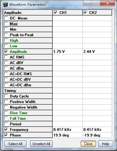

9 Waveform Parameters

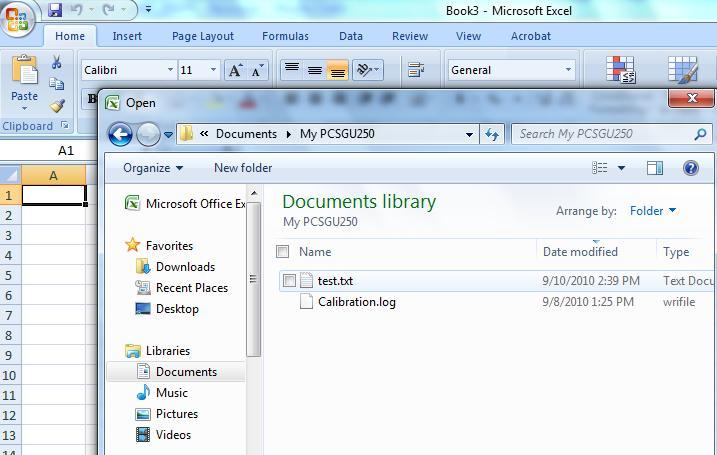
10 Exporting Data To Excel
11 Scaling Required: Time To determine the time to print on the x-axis: Look at TIME STEP: for the number of points (125) that are equal to a time increment (1ms). This means that the time for each point in the column under N should be divided by 125 and then multipled by 1ms to determine the time at which each voltage data point was taken.
12 Scaling Required: 0V To determine the value of the data point for Channel 1 and Channel 2 that is equal to 0V: Look at the numbers above CH1 and CH2 on the GND row. The data point with value 177 is 0V for Channel 1 and with a value of 97 for Channel 2. This means that 177 should be subtracted from each point in the column under CH1 and 97 should be subtracted from each point in the column under CH2.


13 Scaling Required: Absolute Voltage To determine the voltage associated with each data point for Channel 1 and Channel 2: Look at the numbers next to CH1: and CH2: above the GND row. In this case, 1V is equivalent to 32. This means that that the value of the points in the columns CH1 and CH2 should be divided by 32 and then multiplied by 1V to finally obtain the voltage measured by the oscilloscope on Channels 1 and 2 as a function of time.
14 Equivalent Circuit Current, i 1 Suggestion when measuring i 1, use a shunt resistor in the circuit with the same equivalent impedance as the shunt resistors in the original circuit so that you can directly compare the voltage measurements.
15 PSpice Did you know that you can easily switch between several types of simulations by adding the appropriate sources in your schematic and in your simulation profile? For example: If you include a Vsin and a Vac in your circuit, you can chose to simulate either the AC or Transient response when you run the simulation. Note: The additional sources must follow the convention that would be appropriate if you used superposition. I.e., voltage sources must be in series; current sources must be in parallel.
16 PSpice Schematics


17

18 Switching Between Plots
19 PSpice Capture 9.1

20 Select Type of Analysis
RLC Frequency Response
 1. Introduction RLC Frequency Response The student will analyze the frequency response of an RLC circuit excited by a sinusoid. Amplitude and phase shift of circuit components will be analyzed at different
EXPERIMENT NUMBER 10 TRANSIENT ANALYSIS USING PSPICE
 EXPERIMENT NUMBER 10 TRANSIENT ANALYSIS USING PSPICE Objective: To learn to use a circuit simulator package for plotting the response of a circuit in the time domain. Preliminary: Revise laboratory 8 to
Department of Electrical & Computer Engineering Technology. EET 3086C Circuit Analysis Laboratory Experiments. Masood Ejaz
 Department of Electrical & Computer Engineering Technology EET 3086C Circuit Analysis Laboratory Experiments Masood Ejaz Experiment # 1 DC Measurements of a Resistive Circuit and Proof of Thevenin Theorem
Integrators, differentiators, and simple filters
 BEE 233 Laboratory-4 Integrators, differentiators, and simple filters 1. Objectives Analyze and measure characteristics of circuits built with opamps. Design and test circuits with opamps. Plot gain vs.
BME 3512 Bioelectronics Laboratory Two - Passive Filters
 BME 35 Bioelectronics Laboratory Two - Passive Filters Learning Objectives: Understand the basic principles of passive filters. Laboratory Equipment: Agilent Oscilloscope Model 546A Agilent Function Generator
ET 304A Laboratory Tutorial-Circuitmaker For Transient and Frequency Analysis
 ET 304A Laboratory Tutorial-Circuitmaker For Transient and Frequency Analysis All circuit simulation packages that use the Pspice engine allow users to do complex analysis that were once impossible to
Background Theory and Simulation Practice
 CAD and Simulation Objectives Experiment Topic: CAD and Simulation PSpice 9.1 Student Version To obtain your free copy of the software and user s guide, go to Electronics Lab website ( http://www.electronics-lab.com/downloads/schematic/013/
Lab 1: Basic RL and RC DC Circuits
 Name- Surname: ID: Department: Lab 1: Basic RL and RC DC Circuits Objective In this exercise, the DC steady state response of simple RL and RC circuits is examined. The transient behavior of RC circuits
Lab 3: AC Low pass filters (version 1.3)
") Lab 3: AC Low pass filters (version 1.3) WARNING: Use electrical test equipment with care! Always double-check connections before applying power. Look for short circuits, which can quickly destroy expensive
Lab 3: AC Low pass filters (version 1.3) WARNING: Use electrical test equipment with care! Always double-check connections before applying power. Look for short circuits, which can quickly destroy expensive
Lab #5 Steady State Power Analysis
 Lab #5 Steady State Power Analysis Steady state power analysis refers to the power analysis of circuits that have one or more sinusoid stimuli. This lab covers the concepts of RMS voltage, maximum power
Class #7: Experiment L & C Circuits: Filters and Energy Revisited
 Class #7: Experiment L & C Circuits: Filters and Energy Revisited In this experiment you will revisit the voltage oscillations of a simple LC circuit. Then you will address circuits made by combining resistors
Lab 13 AC Circuit Measurements
 Lab 13 AC Circuit Measurements Objectives concepts 1. what is impedance, really? 2. function generator and oscilloscope 3. RMS vs magnitude vs Peak-to-Peak voltage 4. phase between sinusoids skills 1.
ECE ECE285. Electric Circuit Analysis I. Spring Nathalia Peixoto. Rev.2.0: Rev Electric Circuits I
 ECE285 Electric Circuit Analysis I Spring 2014 Nathalia Peixoto Rev.2.0: 140124. Rev 2.1. 140813 1 Lab reports Background: these 9 experiments are designed as simple building blocks (like Legos) and students
Exercise 1: AC Waveform Generator Familiarization
 Exercise 1: AC Waveform Generator Familiarization EXERCISE OBJECTIVE When you have completed this exercise, you will be able to operate an ac waveform generator by using equipment provided. You will verify
LABORATORY 4. Palomar College ENGR210 Spring 2017 ASSIGNED: 3/21/17
 LABORATORY 4 ASSIGNED: 3/21/17 OBJECTIVE: The purpose of this lab is to evaluate the transient and steady-state circuit response of first order and second order circuits. MINIMUM EQUIPMENT LIST: You will
PSPICE SIMULATIONS WITH THE RESONANT INVERTER POWER ELECTRONICS COLORADO STATE UNIVERSITY. Created by Colorado State University student
 PSPICE SIMULATIONS WITH THE RESONANT INVERTER POWER ELECTRONICS COLORADO STATE UNIVERSITY Created by Colorado State University student Page 1 of 13 PURPOSE: The purpose of this lab is to simulate the resonant
Week 9: Series RC Circuit. Experiment 14
 Week 9: Series RC Circuit Experiment 14 Circuit to be constructed It is good practice to short the unused pin on the trimpot when using it as a variable resistor Velleman function generator Shunt resistor
Experiment 8: An AC Circuit
 Experiment 8: An AC Circuit PART ONE: AC Voltages. Set up this circuit. Use R = 500 Ω, L = 5.0 mh and C =.01 μf. A signal generator built into the interface provides the emf to run the circuit from Output
Exercise 2: Inductors in Series and in Parallel
 Exercise 2: Inductors in Series and in Parallel EXERCISE OBJECTIVE When you have completed this exercise, you will be able to determine the total inductance of a circuit containing inductors in series
University of Pennsylvania Department of Electrical and Systems Engineering. ESE 206: Electrical Circuits and Systems II - Lab
 University of Pennsylvania Department of Electrical and Systems Engineering ESE 206: Electrical Circuits and Systems II - Lab AC POWER ANALYSIS AND DESIGN I. Purpose and Equipment: Provide experimental
ENG 100 Lab #2 Passive First-Order Filter Circuits
 ENG 100 Lab #2 Passive First-Order Filter Circuits In Lab #2, you will construct simple 1 st -order RL and RC filter circuits and investigate their frequency responses (amplitude and phase responses).
Lab Session 4 Hardware
 Lab Session 4 Hardware Objectives: Upon completion of this experiment, the student will be able to: -Verifying of Transient response, two port network and Fourier analysis circuits Equipment and Components
1. Hand Calculations (in a manner suitable for submission) For the circuit in Fig. 1 with f = 7.2 khz and a source vin () t 1.
 For the circuit in Fig. 1 with f = 7.2 khz and a source vin () t 1.") Objectives The purpose of this laboratory project is to introduce to equipment, measurement techniques, and simulations commonly used in AC circuit analysis. In this laboratory session, each student will:
Objectives The purpose of this laboratory project is to introduce to equipment, measurement techniques, and simulations commonly used in AC circuit analysis. In this laboratory session, each student will:
Real Analog - Circuits 1 Chapter 11: Lab Projects
 Real Analog - Circuits 1 Chapter 11: Lab Projects 11.2.1: Signals with Multiple Frequency Components Overview: In this lab project, we will calculate the magnitude response of an electrical circuit and
University of Jordan School of Engineering Electrical Engineering Department. EE 219 Electrical Circuits Lab
 University of Jordan School of Engineering Electrical Engineering Department EE 219 Electrical Circuits Lab EXPERIMENT 7 RESONANCE Prepared by: Dr. Mohammed Hawa EXPERIMENT 7 RESONANCE OBJECTIVE This experiment
Lab 4: Analysis of the Stereo Amplifier
 ECE 212 Spring 2010 Circuit Analysis II Names: Lab 4: Analysis of the Stereo Amplifier Objectives In this lab exercise you will use the power supply to power the stereo amplifier built in the previous
Lab 6: Building a Function Generator
 ECE 212 Spring 2010 Circuit Analysis II Names: Lab 6: Building a Function Generator Objectives In this lab exercise you will build a function generator capable of generating square, triangle, and sine
Revised: Summer 2010
 EE 2274 PRE-LAB EXPERIMENT 5 DIODE OR GATE & CLIPPING CIRCUIT COMPLETE PRIOR TO COMING TO LAB Part I: 1. Design a diode, Figure 1 OR gate in which the maximum input current,, Iin is less than 5mA. Show
Experiment 1 Alternating Current with Coil and Ohmic Resistors
 Experiment Alternating Current with Coil and Ohmic esistors - Objects of the experiment - Determining the total impedance and the phase shift in a series connection of a coil and a resistor. - Determining
Exercise 1: Series RLC Circuits
 RLC Circuits AC 2 Fundamentals Exercise 1: Series RLC Circuits EXERCISE OBJECTIVE When you have completed this exercise, you will be able to analyze series RLC circuits by using calculations and measurements.
Welcome to your second Electronics Laboratory Session. In this session you will learn about how to use resistors, capacitors and inductors to make
 Welcome to your second Electronics Laboratory Session. In this session you will learn about how to use resistors, capacitors and inductors to make simple circuits. You will find out how these circuits
Lab 2: Capacitors. Integrator and Differentiator Circuits
 Lab 2: Capacitors Topics: Differentiator Integrator Low-Pass Filter High-Pass Filter Band-Pass Filter Integrator and Differentiator Circuits The simple RC circuits that you built in a previous section
Lab 9 Frequency Domain
 Lab 9 Frequency Domain 1 Components Required Resistors Capacitors Function Generator Multimeter Oscilloscope 2 Filter Design Filters are electric components that allow applying different operations to
PHASORS AND PHASE SHIFT CIRCUITS
 PHASORS AND PHASE SHIFT CIRCUITS YOUR NAME GTA S SIGNATURE LAB MEETING TIME PHASOR CIRCUIT 4. Assemble the series RC circuit with the following circuit element values: C = 0.027 μf R = 10 kω v s (t) =
ME 365 EXPERIMENT 7 SIGNAL CONDITIONING AND LOADING
 ME 365 EXPERIMENT 7 SIGNAL CONDITIONING AND LOADING Objectives: To familiarize the student with the concepts of signal conditioning. At the end of the lab, the student should be able to: Understand the
MEMORIAL UNIVERSITY OF NEWFOUNDLAND. Faculty of Engineering and Applied Science. Laboratory Manual for. Eng Circuit Analysis (2013)
") MEMORIAL UNIVERSITY OF NEWFOUNDLAND Faculty of Engineering and Applied Science Laboratory Manual for Eng. 3821 Circuit Analysis (2013) Instructor: E. W. Gill PREFACE The laboratory exercises in this manual
MEMORIAL UNIVERSITY OF NEWFOUNDLAND Faculty of Engineering and Applied Science Laboratory Manual for Eng. 3821 Circuit Analysis (2013) Instructor: E. W. Gill PREFACE The laboratory exercises in this manual
Class #8: Experiment Diodes Part I
 Class #8: Experiment Diodes Part I Purpose: The objective of this experiment is to become familiar with the properties and uses of diodes. We used a 1N914 diode in two previous experiments, but now we
EE12: Laboratory Project (Part-2) AM Transmitter
 AM Transmitter") EE12: Laboratory Project (Part-2) AM Transmitter ECE Department, Tufts University Spring 2008 1 Objective This laboratory exercise is the second part of the EE12 project of building an AM transmitter in
EE12: Laboratory Project (Part-2) AM Transmitter ECE Department, Tufts University Spring 2008 1 Objective This laboratory exercise is the second part of the EE12 project of building an AM transmitter in
CMOS Inverter & Ring Oscillator
 CMOS Inverter & Ring Oscillator Theory: In this Lab we will implement a CMOS inverter and then use it as a building block for a Ring Oscillator. MOSfets (Metal Oxide Semiconductor Field Effect Transistors)
Laboratory 2 (drawn from lab text by Alciatore)
") Laboratory 2 (drawn from lab text by Alciatore) Instrument Familiarization and Basic Electrical Relations Required Components: 2 1k resistors 2 1M resistors 1 2k resistor Objectives This exercise is designed
Laboratory 2 (drawn from lab text by Alciatore) Instrument Familiarization and Basic Electrical Relations Required Components: 2 1k resistors 2 1M resistors 1 2k resistor Objectives This exercise is designed
PHYS 235: Homework Problems
 PHYS 235: Homework Problems 1. The illustration is a facsimile of an oscilloscope screen like the ones you use in lab. sinusoidal signal from your function generator is the input for Channel 1, and your
Exercise 1: Inductors
 Exercise 1: Inductors EXERCISE OBJECTIVE When you have completed this exercise, you will be able to describe the effect an inductor has on dc and ac circuits by using measured values. You will verify your
Experiment #8: Designing and Measuring a Common-Collector Amplifier
 SCHOOL OF ENGINEERING AND APPLIED SCIENCE DEPARTMENT OF ELECTRICAL AND COMPUTER ENGINEERING ECE 2115: ENGINEERING ELECTRONICS LABORATORY Experiment #8: Designing and Measuring a Common-Collector Amplifier
ELEG 205 Analog Circuits Laboratory Manual Fall 2017
 ELEG 205 Analog Circuits Laboratory Manual Fall 2017 University of Delaware Dr. Mark Mirotznik Kaleb Burd Aric Lu Patrick Nicholson Colby Banbury Table of Contents Policies Policy Page 3 Labs Lab 1: Intro
Since transmission lines can be modeled using PSpice, you can do your analysis by downloading the student version of this excellent program.
 PSpice Analysis Since transmission lines can be modeled using PSpice, you can do your analysis by downloading the student version of this excellent program. PSpice can be downloaded from the following
Group: Names: Resistor Band Colors Measured Value ( ) R 1 : 1k R 2 : 1k R 3 : 2k R 4 : 1M R 5 : 1M
 R 1 : 1k R 2 : 1k R 3 : 2k R 4 : 1M R 5 : 1M") 2.4 Laboratory Procedure / Summary Sheet Group: Names: (1) Select five separate resistors whose nominal values are listed below. Record the band colors for each resistor in the table below. Then connect
2.4 Laboratory Procedure / Summary Sheet Group: Names: (1) Select five separate resistors whose nominal values are listed below. Record the band colors for each resistor in the table below. Then connect
BANGLADESH UNIVERSITY OF ENGINEERING & TECHNOLOGY
 BANGLADESH UNIVERSITY OF ENGINEERING & TECHNOLOGY Electronics Circuits II Laboratory (EEE 208) Simulation Experiment No. 02 Study of the Characteristics and Application of Operational Amplifier (Part B)
ESE 150 Lab 04: The Discrete Fourier Transform (DFT)
") LAB 04 In this lab we will do the following: 1. Use Matlab to perform the Fourier Transform on sampled data in the time domain, converting it to the frequency domain 2. Add two sinewaves together of differing
LAB 04 In this lab we will do the following: 1. Use Matlab to perform the Fourier Transform on sampled data in the time domain, converting it to the frequency domain 2. Add two sinewaves together of differing
EXPERIMENT 9 Problem Solving: First-order Transient Circuits
 EXPERIMENT 9 Problem Solving: First-order Transient Circuits I. Introduction In transient analyses, we determine voltages and currents as functions of time. Typically, the time dependence is demonstrated
Assignment 8 Analyzing Operational Amplifiers in MATLAB and PSpice
 ECEL 301 ECE Laboratory I Dr. A. Fontecchio Assignment 8 Analyzing Operational Amplifiers in MATLAB and PSpice Goal Characterize critical parameters of the inverting or non-inverting opampbased amplifiers.
Electric Circuit II Lab Manual Session #1
 Department of Electrical Engineering Electric Circuit II Lab Manual Session #1 Subject Lecturer Dr. Yasser Hegazy Name:-------------------------------------------------- Group:--------------------------------------------------
EQUIVALENT EQUIPMENT CIRCUITS
 INTRODUCTION EQUIVALENT EQUIPMENT CIRCUITS The student will analyze the internal properties of the equipment used in lab. The input resistance of the oscilloscope and digital multimeter when used as a
Network Analysis I Laboratory EECS 70LA
 Network Analysis I Laboratory EECS 70LA Spring 2018 Edition Written by: Franco De Flaviis, P. Burke Table of Contents Page no. Foreword...3 Summary...4 Report Guidelines and Grading Policy...5 Introduction
Question Paper Profile
 I Scheme Question Paper Profile Program Name : Electrical Engineering Program Group Program Code : EE/EP/EU Semester : Third Course Title : Electrical Circuits Max. Marks : 70 Time: 3 Hrs. Instructions:
Experiment #7: Designing and Measuring a Common-Emitter Amplifier
 SCHOOL OF ENGINEERING AND APPLIED SCIENCE DEPARTMENT OF ELECTRICAL AND COMPUTER ENGINEERING ECE 2115: ENGINEERING ELECTRONICS LABORATORY Experiment #7: Designing and Measuring a Common-Emitter Amplifier
On-Line Students Analog Discovery 2: Arbitrary Waveform Generator (AWG). Two channel oscilloscope
. Two channel oscilloscope") EET 150 Introduction to EET Lab Activity 5 Oscilloscope Introduction Required Parts, Software and Equipment Parts Figure 1, Figure 2, Figure 3 Component /Value Quantity Resistor 10 kω, ¼ Watt, 5% Tolerance
EET 150 Introduction to EET Lab Activity 5 Oscilloscope Introduction Required Parts, Software and Equipment Parts Figure 1, Figure 2, Figure 3 Component /Value Quantity Resistor 10 kω, ¼ Watt, 5% Tolerance
Exercise 1: Touch and Position Sensing
 Exercise 1: Touch and Position Sensing EXERCISE OBJECTIVE When you have completed this exercise, you will be able to describe and demonstrate the use of a capacitance sensor as a touch sensor and a position
Study of Inductive and Capacitive Reactance and RLC Resonance
 Objective Study of Inductive and Capacitive Reactance and RLC Resonance To understand how the reactance of inductors and capacitors change with frequency, and how the two can cancel each other to leave
EK307 Passive Filters and Steady State Frequency Response
 EK307 Passive Filters and Steady State Frequency Response Laboratory Goal: To explore the properties of passive signal-processing filters Learning Objectives: Passive filters, Frequency domain, Bode plots
Operational Amplifiers: Part II
 1. Introduction Operational Amplifiers: Part II The name "operational amplifier" comes from this amplifier's ability to perform mathematical operations. Three good examples of this are the summing amplifier,
Experiment 9 AC Circuits
 Experiment 9 AC Circuits "Look for knowledge not in books but in things themselves." W. Gilbert (1540-1603) OBJECTIVES To study some circuit elements and a simple AC circuit. THEORY All useful circuits
1.5k. (a) Resistive Circuit (b) Capacitive Circuit
 Resistive Circuit (b) Capacitive Circuit") Objective Information The purposes of this laboratory project are to become further acquainted with the use of an oscilloscope, and to observe the behavior of resistor and resistor capacitor circuits.
Objective Information The purposes of this laboratory project are to become further acquainted with the use of an oscilloscope, and to observe the behavior of resistor and resistor capacitor circuits.
UNIVERSITY OF NORTH CAROLINA AT CHARLOTTE Department of Electrical and Computer Engineering
 UNIVERSITY OF NORTH CAROLINA AT CHARLOTTE Department of Electrical and Computer Engineering EXPERIMENT 8 NETWORK ANALYSIS OBJECTIVES The purpose of this experiment is to mathematically analyze a circuit
EE 230 Lab Lab nf C 2. A. Low-Q low-pass active filters. (a) 10 k! Figure 1. (a) First-order low-pass. (b) Second-order low-pass.
 10 k! Figure 1. (a) First-order low-pass. (b) Second-order low-pass.") Second-order filter circuits This time, we measure frequency response plots for second-order filters. We start by examining a simple 2nd-order low-pass filter. The we look at the various arrangements of
Second-order filter circuits This time, we measure frequency response plots for second-order filters. We start by examining a simple 2nd-order low-pass filter. The we look at the various arrangements of
University of Michigan EECS 311: Electronic Circuits Fall 2008 LAB 2 ACTIVE FILTERS
 University of Michigan EECS 311: Electronic Circuits Fall 2008 LAB 2 ACTIVE FILTERS Issued 9/22/2008 Pre Lab Completed 9/29/2008 Lab Due in Lecture 10/6/2008 Introduction In this lab you will design a
LABORATORY 7 v2 BOOST CONVERTER
 University of California Berkeley Department of Electrical Engineering and Computer Sciences EECS 100, Professor Bernhard Boser LABORATORY 7 v2 BOOST CONVERTER In many situations circuits require a different
ESE 150 Lab 04: The Discrete Fourier Transform (DFT)
") LAB 04 In this lab we will do the following: 1. Use Matlab to perform the Fourier Transform on sampled data in the time domain, converting it to the frequency domain 2. Add two sinewaves together of differing
LAB 04 In this lab we will do the following: 1. Use Matlab to perform the Fourier Transform on sampled data in the time domain, converting it to the frequency domain 2. Add two sinewaves together of differing
PHYS 3322 Modern Laboratory Methods I AC R, RC, and RL Circuits
 Purpose PHYS 3322 Modern Laboratory Methods I AC, C, and L Circuits For a given frequency, doubling of the applied voltage to resistors, capacitors, and inductors doubles the current. Hence, each of these
STUDY OF RC AND RL CIRCUITS Venue: Microelectronics Laboratory in E2 L2
 EXPERIMENT #1 STUDY OF RC AND RL CIRCUITS Venue: Microelectronics Laboratory in E2 L2 I. INTRODUCTION This laboratory is about verifying the transient behavior of RC and RL circuits. You need to revise
Exercise 2: Parallel RLC Circuits
 RLC Circuits AC 2 Fundamentals Exercise 2: Parallel RLC Circuits EXERCSE OBJECTVE When you have completed this exercise, you will be able to analyze parallel RLC circuits by using calculations and measurements.
University of North Carolina, Charlotte Department of Electrical and Computer Engineering ECGR 3157 EE Design II Fall 2009
 University of North Carolina, Charlotte Department of Electrical and Computer Engineering ECGR 3157 EE Design II Fall 2009 Lab 1 Power Amplifier Circuits Issued August 25, 2009 Due: September 11, 2009
THE UNIVERSITY OF HONG KONG. Department of Electrical and Electrical Engineering
 THE UNIVERSITY OF HONG KONG Department of Electrical and Electrical Engineering Experiment EC1 The Common-Emitter Amplifier Location: Part I Laboratory CYC 102 Objective: To study the basic operation and
EELE 201 Circuits I. Fall 2013 (4 Credits)
") EELE 201 Circuits I Instructor: Fall 2013 (4 Credits) Jim Becker 535 Cobleigh Hall 994-5988 Office hours: Monday 2:30-3:30 pm and Wednesday 3:30-4:30 pm or by appointment EMAIL: For EELE 201-related questions,
EELE 201 Circuits I Instructor: Fall 2013 (4 Credits) Jim Becker 535 Cobleigh Hall 994-5988 Office hours: Monday 2:30-3:30 pm and Wednesday 3:30-4:30 pm or by appointment EMAIL: For EELE 201-related questions,
BME/ISE 3512 Bioelectronics Laboratory Two - Passive Filters
 BME/ISE 35 Bioelectronics Laboratory Two - Passive Filters Learning Objectives: Understand the basic principles of passive filters. Supplies and Components: Breadboard 4.7 K Resistor 0.047 F Capacitor
EE-2302 Passive Filters and Frequency Response
 EE2302 Passive Filters and Frequency esponse Objective he student should become acquainted with simple passive filters for performing highpass, lowpass, and bandpass operations. he experimental tasks also
Lab 2: Common Emitter Design: Part 2
 Lab 2: Common Emitter Design: Part 2 ELE 344 University of Rhode Island, Kingston, RI 02881-0805, U.S.A. 1 Linearity in High Gain Amplifiers The common emitter amplifier, shown in figure 1, will provide
Operational Amplifiers 2 Active Filters ReadMeFirst
 Operational Amplifiers 2 Active Filters ReadMeFirst Lab Summary In this lab you will build two active filters on a breadboard, using an op-amp, resistors, and capacitors, and take data for the magnitude
Experiment 8 Frequency Response
 Experiment 8 Frequency Response W.T. Yeung, R.A. Cortina, and R.T. Howe UC Berkeley EE 105 Spring 2005 1.0 Objective This lab will introduce the student to frequency response of circuits. The student will
Lab Reference Manual. ECEN 326 Electronic Circuits. Texas A&M University Department of Electrical and Computer Engineering
 Lab Reference Manual ECEN 326 Electronic Circuits Texas A&M University Department of Electrical and Computer Engineering Contents 1. Circuit Analysis in PSpice 3 1.1 Transient and DC Analysis 3 1.2 Measuring
STATION NUMBER: LAB SECTION: Filters. LAB 6: Filters ELECTRICAL ENGINEERING 43/100 INTRODUCTION TO MICROELECTRONIC CIRCUITS
 Lab 6: Filters YOUR EE43/100 NAME: Spring 2013 YOUR PARTNER S NAME: YOUR SID: YOUR PARTNER S SID: STATION NUMBER: LAB SECTION: Filters LAB 6: Filters Pre- Lab GSI Sign- Off: Pre- Lab: /40 Lab: /60 Total:
EE4902 C Lab 7
 EE4902 C2007 - Lab 7 MOSFET Differential Amplifier Resistive Load Active Load PURPOSE: The primary purpose of this lab is to measure the performance of the differential amplifier. This is an important
STEP RESPONSE OF 1 ST AND 2 ND ORDER CIRCUITS
 STEP RESPONSE OF 1 ST AND 2 ND ORDER CIRCUITS YOUR NAME GTA S SIGNATURE LAB MEETING TIME Objectives: To observe responses of first and second order circuits - RC, RL and RLC circuits, source-free or with
EE 210 Lab Exercise #5: OP-AMPS I
 EE 210 Lab Exercise #5: OP-AMPS I ITEMS REQUIRED EE210 crate, DMM, EE210 parts kit, T-connector, 50Ω terminator, Breadboard Lab report due at the ASSIGNMENT beginning of the next lab period Data and results
LAB 8: Activity P52: LRC Circuit
 LAB 8: Activity P52: LRC Circuit Equipment: Voltage Sensor 1 Multimeter 1 Patch Cords 2 AC/DC Electronics Lab (100 μf capacitor; 10 Ω resistor; Inductor Coil; Iron core; 5 inch wire lead) The purpose of
EE 233 Circuit Theory Lab 3: First-Order Filters
 EE 233 Circuit Theory Lab 3: First-Order Filters Table of Contents 1 Introduction... 1 2 Precautions... 1 3 Prelab Exercises... 2 3.1 Inverting Amplifier... 3 3.2 Non-Inverting Amplifier... 4 3.3 Integrating
AC CIRCUITS - CAPACITORS AND INDUCTORS
 EXPRIMENT#8 AC CIRCUITS - CAPACITORS AND INDUCTORS NOTE: Two weeks are allocated for this experiment. Before performing this experiment, review the Proper Oscilloscope Use section of Experiment #7. Objective
Objective of the Lecture
 Objective of the Lecture Present Kirchhoff s Current and Voltage Laws. Chapter 5.6 and Chapter 6.3 Principles of Electric Circuits Chapter4.6 and Chapter 5.5 Electronics Fundamentals or Electric Circuit
Week 12 Experiment 21. Design a Traffic Arrow
 Week 12 Experiment 21 Design a Traffic Arrow Just so it is clear This is it. Last official experiment for the semester. It is your option as to whether or not you do a make-up experiment. This is the last
University of Michigan EECS 311: Electronic Circuits Fall 2009 LAB 2 NON IDEAL OPAMPS
 University of Michigan EECS 311: Electronic Circuits Fall 2009 LAB 2 NON IDEAL OPAMPS Issued 10/5/2008 Pre Lab Completed 10/12/2008 Lab Due in Lecture 10/21/2008 Introduction In this lab you will characterize
ECE 310L : LAB 9. Fall 2012 (Hay)
") ECE 310L : LAB 9 PRELAB ASSIGNMENT: Read the lab assignment in its entirety. 1. For the circuit shown in Figure 3, compute a value for R1 that will result in a 1N5230B zener diode current of approximately
ECE 310L : LAB 9 PRELAB ASSIGNMENT: Read the lab assignment in its entirety. 1. For the circuit shown in Figure 3, compute a value for R1 that will result in a 1N5230B zener diode current of approximately
Analysis and Measurement of a Resistor Bridge Circuit with Three Voltage Sources
 Analysis and Measurement of a Resistor Bridge Circuit with Three Voltage Sources EL 111 - DC Fundamentals Required Laboratory Project By: Walter Banzhaf, E.K. Smith, and Winfield Young University of Hartford
Questions Bank of Electrical Circuits
 Questions Bank of Electrical Circuits 1. If a 100 resistor and a 60 XL are in series with a 115V applied voltage, what is the circuit impedance? 2. A 50 XC and a 60 resistance are in series across a 110V
Exercise 2: Demodulation (Quadrature Detector)
") Analog Communications Angle Modulation and Demodulation Exercise 2: Demodulation (Quadrature Detector) EXERCISE OBJECTIVE When you have completed this exercise, you will be able to explain demodulation
Analog Communications Angle Modulation and Demodulation Exercise 2: Demodulation (Quadrature Detector) EXERCISE OBJECTIVE When you have completed this exercise, you will be able to explain demodulation
Laboratory 2. Lab 2. Instrument Familiarization and Basic Electrical Relations. Required Components: 2 1k resistors 2 1M resistors 1 2k resistor
 Laboratory 2 nstrument Familiarization and Basic Electrical Relations Required Components: 2 1k resistors 2 1M resistors 1 2k resistor 2.1 Objectives This exercise is designed to acquaint you with the
Electronics and Instrumentation ENGR-4300 Spring 2004 Section Experiment 5 Introduction to AC Steady State
 Experiment 5 Introduction to C Steady State Purpose: This experiment addresses combinations of resistors, capacitors and inductors driven by sinusoidal voltage sources. In addition to the usual simulation
The RLC Series Circuit with an AC Source
 The R Series ircuit with an A Source Introduction Ohm s law and R circuit labs use a steady current. However, this lab uses a different power supply, which is alternating current (A). The previous electronics
NI Elvis Virtual Instrumentation And Prototyping Board
 NI Elvis Virtual Instrumentation And Prototyping Board Objectives: a) Become familiar with NI Elvis hardware ( breadboard ) and software b) Learn resistor color codes c) Learn how to use Digital Multimeter
EE 2274 RC and Op Amp Circuit Completed Prior to Coming to Lab. Prelab Part I: RC Circuit
 EE 2274 RC and Op Amp Circuit Completed Prior to Coming to Lab Prelab Part I: RC Circuit 1. Design a high pass filter (Fig. 1) which has a break point f b = 1 khz at 3dB below the midband level (the -3dB
Experiment 1 LRC Transients
 Physics 263 Experiment 1 LRC Transients 1 Introduction In this experiment we will study the damped oscillations and other transient waveforms produced in a circuit containing an inductor, a capacitor,
BME/ISE 3511 Laboratory One - Laboratory Equipment for Measurement. Introduction to biomedical electronic laboratory instrumentation and measurements.
 BME/ISE 3511 Laboratory One - Laboratory Equipment for Measurement Learning Objectives: Introduction to biomedical electronic laboratory instrumentation and measurements. Supplies and Components: Breadboard