MAKEVMA502 BASIC DIY KIT WITH ATMEGA2560 FOR ARDUINO USER MANUAL
|
|
|
- Phebe Anthony
- 5 years ago
- Views:
Transcription


1 BASIC DIY KIT WITH ATMEGA2560 FOR ARDUINO USER MANUAL


2 USER MANUAL 1. Introduction To all residents of the European Union Important environmental information about this product This symbol on the device or the package indicates that disposal of the device after its lifecycle could harm the environment. Do not dispose of the unit (or batteries) as unsorted municipal waste; it should be taken to a specialized company for recycling. This device should be returned to your distributor or to a local recycling service. Respect the local environmental rules. If in doubt, contact your local waste disposal authorities. Please read the manual thoroughly before bringing this device into service. If the device was damaged in transit, do not install or use it and contact your dealer. 2. Safety Instructions This device can be used by children aged from 8 years and above, and persons with reduced physical, sensory or mental capabilities or lack of experience and knowledge if they have been given supervision or instruction concerning the use of the device in a safe way and understand the hazards involved. Children shall not play with the device. Cleaning and user maintenance shall not be made by children without supervision. Indoor use only. Keep away from rain, moisture, splashing and dripping liquids. 3. General Guidelines Familiarise yourself with the functions of the device before actually using it. All modifications of the device are forbidden for safety reasons. Damage caused by user modifications to the device is not covered by the warranty. Only use the device for its intended purpose. Using the device in an unauthorised way will void the warranty. Damage caused by disregard of certain guidelines in this manual is not covered by the warranty and the dealer will not accept responsibility for any ensuing defects or problems. The dealers cannot be held responsible for any damage (extraordinary, incidental or indirect) of any nature (financial, physical ) arising from the possession, use or failure of this product. Due to constant product improvements, the actual product appearance might differ from the shown images. Product images are for illustrative purposes only. Do not switch the device on immediately after it has been exposed to changes in temperature. Protect the device against damage by leaving it switched off until it has reached room temperature. Keep this manual for future reference. V /11/2017 2

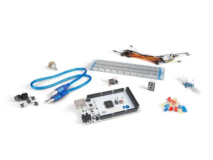
3 4. What is Arduino Arduino is an open-source prototyping platform based in easy-to-use hardware and software. Arduino boards are able to read inputs light-on sensor, a finger on a button or a Twitter message and turn it into an output activating of a motor, turning on an LED, publishing something online. You can tell your board what to do by sending a set of instructions to the microcontroller on the board. To do so, you use the Arduino programming language (based on Wiring) and the Arduino software IDE (based on Processing). Surf to and for more information. 5. Contents 1 x ATmega2560 Mega development board (MAKEVMA101) 15 x LED (different colors) 8 x 220 Ω resistor (RA220E0) 5 x 1K resistor (RA1K0) 5 x 10K resistor (RA10K0) 1 x 830-hole breadboard 4 x 4-pin key switch 1 x active buzzer (MAKEVMA319) 1 x passive buzzer 1 x infrared sensor diode 1 x LM35 temperature sensor (LM35DZ) 2 x ball tilt switch (similar to MERS4 and MERS5) 3 x photosensitive resistor LDR (similar to LDR04) 1 x single-digit 7-segment LED display 30 x breadboard jumper wire 1 x USB cable 6. The ATmega2560 Mega MAKEVMA101 The MAKEVMA101 (Arduino compatible) Mega 2560 is a microcontroller board based on the ATmega2560. It has 54 digital input/output pins (of which 15 can be used as PWM outputs), 16 analogue inputs, 4 UARTs (hardware serial ports), a 16 MHz crystal oscillator, a USB connection, a power jack, an ICSP header, and a reset button. It contains everything needed to support the microcontroller. Connect it to a computer with a USB cable or power it with an AC-to-DC adapter or battery to get started. The Mega is compatible with most shields designed for the Arduino Duemilanove or Diecimila. V /11/2017 3
... 7-12 VDC input voltage (limits)... 6-20 VDC digital I/O pins.")
4 1 USB interface 7 Atmel mega ICSP for 16U2 8 reset button 3 digital I/O 9 digital I/O 4 Atmel mega16u VDC power input 5 ICSP for mega power and ground pins 6 16 MHz clock 12 analogue input pins microcontroller... ATmega2560 operating voltage... 5 VDC input voltage (recommended) VDC input voltage (limits) VDC digital I/O pins (of which 15 provide PWM output) analogue input pins DC current per I/O pin ma DC current for 3.3 V pin ma flash memory kb of which 8 kb used by bootloader SRAM... 8 kb EEPROM... 4 kb clock speed MHz dimensions length mm width mm weight g 7. Operation 7.1 The Breadboard Breadboards are one of the most fundamental pieces when learning how to build circuits. In this tutorial, we will introduce you to what breadboards are and how they work. Let us look at a larger, more typical breadboard. Aside from the horizontal rows, breadboards have what are called power rails that run vertically along the sides. Power rails. V /11/2017 4

5 Chips have legs that come out of both sides and fit perfectly over the ravine. Since each leg on the IC is unique, we do not want both sides to be connected to each other. That is where the separation in the middle of the board comes in handy. Thus, we can connect components to each side of the IC without interfering with the functionality of the leg on the opposite side. Ravine. 7.2 A Blinking LED Let s start with a simple experiment. We are going to connect an LED to one of the digital pins rather than using LED13, which is soldered to the board. Required Hardware 1 x red M5 LED 1 x 220 Ω resistor 1 x breadboard jumper wires as needed Follow the diagram below. We are using digital pin 10, and connecting the LED to a 220 Ω resistor to avoid high-current damaging the LED. V /11/2017 5

6 Connection Programming Code Result After programming, you will see the LED connected to pin 10 blinking, with an interval of approximately one second. Congratulations, the experiment is now successfully completed! V /11/2017 6
7 7.3 PWM Gradational LED PWM (Pulse Width Modulation) is a technique used to encode analogue signal levels into digital ones. A computer cannot output analogue voltage but only digital voltage values. So, we will be using a high-resolution counter to encode a specific analogue signal level by modulating the duty cycle of PWM. The PWM signal is also digitalized because in any given moment, fully on DC power is either 5 V (on) of 0 V (off). The voltage or current is fed to the analogue load (the device using the power) by repeated pulse sequence being on or off. Being on, the current is fed to the load; being off, it is not. With the adequate bandwidth, any analogue value can be encoded using PWM. The output voltage value is calculated via the on and off time. output voltage = (turn on time/pulse time) * maximum voltage value PWM has many applications: lamp brightness regulation, motor speed regulation, sound making, etc. The following are the basic parameters of PWM: There are six PQM interfaces on Arduino, namely digital pin, 3, 5, 6, 9, 10 and 11. In this experiment, we will be using a potentiometer to control the LED brightness. V /11/2017 7

8 Required Hardware 1 x variable resistor 1 x red M5 LED 1 x 220 Ω resistor 1 x breadboard jumper wires as needed Connection Programming Code V /11/2017 8

9 In this code, we are using the analogwrite (PWM interface, analogue value) function. We will read the analogue value of the potentiometer and assign the value to PWM port, so there will be corresponding change to the brightness of the LED. One final part will be displaying the analogue value on the screen. You can consider this as the analogue value reading project adding the PWM analogue value assigning part. Result After programming, rotate the potentiometer knob to see changes of the displaying value. Also, note the obvious change of brightness on the breadboard. 7.4 The Active Buzzer An active buzzer is widely used on computers, printers, alarms, etc. as a sound-making element. It has an inner vibration source. Simply connect it with a 5 V power supply to make it buzz constantly. Required Hardware 1 x buzzer 1 x key 1 x breadboard jumper wires as needed Connection V /11/2017 9
10 Programming Code Result After programming, the buzzer should ring. 7.5 The Photosensitive Resistor A photoresistor is a resistor whose resistance varies according to different light strengths. It is based on the photoelectric effect of a semiconductor. If the incident light is intense, the resistance reduces; if the incident light is weak, the resistant increases. A photovaristor is commonly applied in the measurement of light, light control and photovoltaic conversion. Let s start with a relative simple experiment. The photovaristor is an element that changes its resistance as light strength changes. Refer to the PWM experiment, replacing the potentiometer with a photovaristor. When there is a change in light strength, there will be a corresponding change on the LED. Required Hardware 1 x photoresistor 1 x red M5 LED 1 x 10KΩ resistor 1 x 220 Ω resistor 1 x breadboard jumper wires as needed V /11/

11 Connection Programming Code Result After programming, change the light strength around the photovaristor and observe the LED changing! V /11/

12 7.6 The Flame Sensor A flame sensor (IR receiving diode) is specifically used on robots to find the fire source. This sensor is highly sensitive to flames. A flame sensor has a specifically designed IR tube to detect fire. The brightness of the flames will then be converted to a fluctuating level signal. The signals are the input into the central processor. Required Hardware 1 x flame sensor 1 x buzzer 1 x 10KΩ resistor 1 x breadboard jumper wires as needed Connection Connect the negative to the 5 V pin and the positive to the resistor. Connect the other end of the resistor to GND. Connect one end of a jumper wire to a clip, which is electrically connected to sensor positive, the other end to the analogue pin. V /11/

13 Programming Code 7.7 The LM35 Temperature Sensor The LM35 is a common and easy-to-use temperature sensor. It does not require other hardware, you just need an analogue port to make it work. The difficulty lies in compiling the code to convert the analogue value it reads to Celsius temperature. Required Hardware 1 x LM35 sensor 1 x breadboard jumper wires as needed V /11/

14 Connection Programming Code Result After programming, open the monitoring window to see the current temperature. V /11/


15 7.8 The Tilt Sensor Switch A tilt sensor will detect orientation and inclination. They are small, low power and easy-to-use. If used properly, they will not wear out. Their simplicity makes them popular for toys, gadgets and other appliances. They are referred to as mercury, tilt or rolling ball switches. The Simple Tilt-Activated LED This is the most basic connection of a tilt switch, but can be a handy while one is learning about them. Simply connect in series with an LED, resistor and battery. Reading the Switch State with a Microcontroller The layout below shows a 10K pull-up resistor. The code states the built-in pull-up resistor that you can turn on by setting an input pin to the high output. If you use the internal pull-up you can skip the external one. V /11/
16 Programming Code V /11/
. Segment displays can be divided into 7-segment and 8-segment displays.")
. For the common anode display, connect the common anode (COM) to +5 V.")
17 7.9 One-Digit Seven-Segment Display MAKEVMA502 LED segment displays are common for displaying numerical information. They are widely applied on displays of ovens, washing machines, etc. the LED segment display is a semiconductor light-emitting device. Its basic unit is an LED (light-emitting diode). Segment displays can be divided into 7-segment and 8-segment displays. According to the wiring method, LED segment displays can be divided into displays with common anode and displays with common cathode. Common anode displays refer to displays that combine all the anodes of the LED units into one common anode (COM). For the common anode display, connect the common anode (COM) to +5 V. When the cathode level of a certain segment is low, the segment is on; when the cathode level of a certain segment is high, the segment is off. For the common cathode display, connect the common cathode (COM) to GND. When the anode level of a certain segment is high, the segment is on; when the anode level of a certain segment is low, the segment is off. Connection V /11/
18 Programming Code V /11/
19 COPYRIGHT NOTICE All worldwide rights reserved. No part of this manual may be copied, reproduced, translated or reduced to any electronic medium or otherwise without the prior written consent of the copyright holder. V /11/
VMA502 BASIC DIY KIT WITH ATMEGA2560 FOR ARDUINO USER MANUAL
 BASIC DIY KIT WITH ATMEGA2560 FOR ARDUINO USER MANUAL USER MANUAL 1. Introduction To all residents of the European Union Important environmental information about this product This symbol on the device
VMA205 WIFI ESP8266 SHIELD
 WIFI ESP8266 SHIELD USER MANUAL USER MANUAL 1. Introduction To all residents of the European Union Important environmental information about this product This symbol on the device or the package indicates
VMA333 TB6560 3A STEPPER MOTOR DRIVER BOARD USER MANUAL
 TB6560 3A STEPPER MOTOR DRIVER BOARD USER MANUAL USER MANUAL 1. Introduction To all residents of the European Union Important environmental information about this product This symbol on the device or the
VMA329 FINGERPRINT SENSOR ZFM-708 USER MANUAL
 FINGERPRINT SENSOR ZFM-708 USER MANUAL USER MANUAL 1. Introduction To all residents of the European Union Important environmental information about this product This symbol on the device or the package
VMA314 PIR MOTION SENSOR FOR ARDUINO USER MANUAL
 PIR MOTION SENSOR FOR ARDUINO USER MANUAL USER MANUAL 1. Introduction To all residents of the European Union Important environmental information about this product This symbol on the device or the package
VMA435 DIGITAL ROTARY ENCODER MODULE USER MANUAL
 DIGITAL ROTARY ENCODER MODULE USER MANUAL USER MANUAL 1. Introduction To all residents of the European Union Important environmental information about this product This symbol on the device or the package
HAW-Arduino. Sensors and Arduino F. Schubert HAW - Arduino 1
 HAW-Arduino Sensors and Arduino 14.10.2010 F. Schubert HAW - Arduino 1 Content of the USB-Stick PDF-File of this script Arduino-software Source-codes Helpful links 14.10.2010 HAW - Arduino 2 Report for
Lab 2: Blinkie Lab. Objectives. Materials. Theory
 Lab 2: Blinkie Lab Objectives This lab introduces the Arduino Uno as students will need to use the Arduino to control their final robot. Students will build a basic circuit on their prototyping board and
FABO ACADEMY X ELECTRONIC DESIGN
 ELECTRONIC DESIGN MAKE A DEVICE WITH INPUT & OUTPUT The Shanghaino can be programmed to use many input and output devices (a motor, a light sensor, etc) uploading an instruction code (a program) to it
Arduino STEAM Academy Arduino STEM Academy Art without Engineering is dreaming. Engineering without Art is calculating. - Steven K.
 Arduino STEAM Academy Arduino STEM Academy Art without Engineering is dreaming. Engineering without Art is calculating. - Steven K. Roberts Page 1 See Appendix A, for Licensing Attribution information
Shock Sensor Module This module is digital shock sensor. It will output a high level signal when it detects a shock event.
 Item Picture Description KY001: Temperature This module measures the temperature and reports it through the 1-wire bus digitally to the Arduino. DS18B20 (https://s3.amazonaws.com/linksprite/arduino_kits/advanced_sensors_kit/ds18b20.pdf)
LPTDX CHANNEL DIMMER PACK
 12-CHANNEL DIMMER PACK 1. Introduction To all residents of the European Union Important environmental information about this product This symbol on the device or the package indicates that disposal of
Breadboard Arduino Compatible Assembly Guide
 (BBAC) breadboard arduino compatible Breadboard Arduino Compatible Assembly Guide (BBAC) A Few Words ABOUT THIS KIT The overall goal of this kit is fun. Beyond this, the aim is to get you comfortable using
Lab 2.4 Arduinos, Resistors, and Circuits
 Lab 2.4 Arduinos, Resistors, and Circuits Objectives: Investigate resistors in series and parallel and Kirchoff s Law through hands-on learning Get experience using an Arduino hat you need: Arduino Kit:
Lecture 4: Basic Electronics. Lecture 4 Brief Introduction to Electronics and the Arduino
 Lecture 4: Basic Electronics Lecture 4 Page: 1 Brief Introduction to Electronics and the Arduino colintan@nus.edu.sg Lecture 4: Basic Electronics Page: 2 Objectives of this Lecture By the end of today
Index. n A. n B. n C. Base biasing transistor driver circuit, BCD-to-Decode IC, 44 46
 Index n A Android Droid X smartphone, 165 Arduino-based LCD controller with an improved event trigger, 182 with auto-adjust contrast control, 181 block diagram, 189, 190 circuit diagram, 187, 189 delay()
Workshops Elisava Introduction to programming and electronics (Scratch & Arduino)
") Workshops Elisava 2011 Introduction to programming and electronics (Scratch & Arduino) What is programming? Make an algorithm to do something in a specific language programming. Algorithm: a procedure
Workshops Elisava 2011 Introduction to programming and electronics (Scratch & Arduino) What is programming? Make an algorithm to do something in a specific language programming. Algorithm: a procedure
Study of M.A.R.S. (Multifunctional Aero-drone for Remote Surveillance)
") Study of M.A.R.S. (Multifunctional Aero-drone for Remote Surveillance) Supriya Bhuran 1, Rohit V. Agrawal 2, Kiran D. Bombe 2, Somiran T. Karmakar 2, Ninad V. Bapat 2 1 Assistant Professor, Dept. Instrumentation,
Study of M.A.R.S. (Multifunctional Aero-drone for Remote Surveillance) Supriya Bhuran 1, Rohit V. Agrawal 2, Kiran D. Bombe 2, Somiran T. Karmakar 2, Ninad V. Bapat 2 1 Assistant Professor, Dept. Instrumentation,
Optimization and Performance Evaluation of Single Axis Arduino Solar Tracker
 Optimization and Performance Evaluation of Single Axis Arduino Solar Tracker B. Sujatha Assistant Professor, Dept of EEE sujathareddy4311@gmail.com J. Sravana Kalyani UG Student, Dept of EEE sravanijandhyala066@gmail.com
Controlling DC Brush Motor using MD10B or MD30B. Version 1.2. Aug Cytron Technologies Sdn. Bhd.
 PR10 Controlling DC Brush Motor using MD10B or MD30B Version 1.2 Aug 2008 Cytron Technologies Sdn. Bhd. Information contained in this publication regarding device applications and the like is intended
Attribution Thank you to Arduino and SparkFun for open source access to reference materials.
 Attribution Thank you to Arduino and SparkFun for open source access to reference materials. Contents Parts Reference... 1 Installing Arduino... 7 Unit 1: LEDs, Resistors, & Buttons... 7 1.1 Blink (Hello
Arduino Uno Pinout Book
 Arduino Uno Pinout Book 1 / 6 2 / 6 3 / 6 Arduino Uno Pinout Book Arduino Uno pinout - Power Supply. There are 3 ways to power the Arduino Uno: Barrel Jack - The Barrel jack, or DC Power Jack can be used
DASL 120 Introduction to Microcontrollers
 DASL 120 Introduction to Microcontrollers Lecture 2 Introduction to 8-bit Microcontrollers Introduction to 8-bit Microcontrollers Introduction to 8-bit Microcontrollers Introduction to Atmel Atmega328
ESE141 Circuit Board Instructions
 ESE141 Circuit Board Instructions Board Version 2.1 Fall 2006 Washington University Electrical Engineering Basics Because this class assumes no prior knowledge or skills in electrical engineering, electronics
Objectives: Learn what an Arduino is and what it can do Learn what an LED is and how to use it Be able to wire and program an LED to blink
 Objectives: Learn what an Arduino is and what it can do Learn what an LED is and how to use it Be able to wire and program an LED to blink By the end of this session: You will know how to use an Arduino
Electronic Components
 Electronic Components Arduino Uno Arduino Uno is a microcontroller (a simple computer), it has no way to interact. Building circuits and interface is necessary. Battery Snap Battery Snap is used to connect
Lesson 3: Arduino. Goals
 Introduction: This project introduces you to the wonderful world of Arduino and how to program physical devices. In this lesson you will learn how to write code and make an LED flash. Goals 1 - Get to
International Journal of Applied Sciences, Engineering and Management ISSN , Vol. 06, No. 02, March 2017, pp
 Intelligent Street Lighting System S. Jagan Mohan Rao 1, N. Kundana 2, N. Prasanti 2, U. Bhargav Teja 2, Y. Mukhesh 2 1 Professor, Vice Principal, Ramachandra College of Engineering, Eluru, Andhra Pradesh,
ARDUINO / GENUINO. start as professional. short course in a book. faculty of engineering technology
 ARDUINO / GENUINO start as professional short course in a book faculty of engineering technology Publisher Universiti Malaysia Pahang Kuantan 2017 Copyright Universiti Malaysia Pahang, 2017 First Published,
PCB & Circuit Designing (Summer Training Program) 6 Weeks/ 45 Days PRESENTED BY
 6 Weeks/ 45 Days PRESENTED BY") PCB & Circuit Designing (Summer Training Program) 6 Weeks/ 45 Days PRESENTED BY RoboSpecies Technologies Pvt. Ltd. Office: D-66, First Floor, Sector- 07, Noida, UP Contact us: Email: stp@robospecies.com
PCB & Circuit Designing (Summer Training Program) 6 Weeks/ 45 Days PRESENTED BY RoboSpecies Technologies Pvt. Ltd. Office: D-66, First Floor, Sector- 07, Noida, UP Contact us: Email: stp@robospecies.com
Introduction to the Arduino Kit
 1 Introduction to the Arduino Kit Introduction Arduino is an open source microcontroller platform used for sensing both digital and analog input signals and for sending digital and analog output signals
Robotics & Embedded Systems (Summer Training Program) 4 Weeks/30 Days
 4 Weeks/30 Days") (Summer Training Program) 4 Weeks/30 Days PRESENTED BY RoboSpecies Technologies Pvt. Ltd. Office: D-66, First Floor, Sector- 07, Noida, UP Contact us: Email: stp@robospecies.com Website: www.robospecies.com
(Summer Training Program) 4 Weeks/30 Days PRESENTED BY RoboSpecies Technologies Pvt. Ltd. Office: D-66, First Floor, Sector- 07, Noida, UP Contact us: Email: stp@robospecies.com Website: www.robospecies.com
Arduino An Introduction
 Arduino An Introduction Hardware and Programming Presented by Madu Suthanan, P. Eng., FEC. Volunteer, Former Chair (2013-14) PEO Scarborough Chapter 2 Arduino for Mechatronics 2017 This note is for those
PIR Motion Detector Experiment. In today s crime infested society, security systems have become a much more
 PIR Motion Detector Experiment I. Rationale In today s crime infested society, security systems have become a much more necessary and sought out addition to homes or stores. Motion detectors provide a
Autonomous. Chess Playing. Robot
 Autonomous Chess Playing Robot Team Members 1. Amit Saharan 2. Gaurav Raj 3. Riya Gupta 4. Saumya Jaiswal 5. Shilpi Agrawal 6. Varun Gupta Mentors 1. Mukund Tibrewal 2. Hardik Soni 3. Zaid Tasneem Abstract
Energy Efficiency for Secured Smart Village using IoT
 Energy Efficiency for Secured Smart Village using IoT S.P. Angelin Claret 1 1 Asst. Prof, Department of Computer Science, SRM Institute of Science & Technology, Chennai. Abstract: This paper is all about
Training Schedule. Robotic System Design using Arduino Platform
 Training Schedule Robotic System Design using Arduino Platform Session - 1 Embedded System Design Basics : Scope : To introduce Embedded Systems hardware design fundamentals to students. Processor Selection
Sten-Bot Robot Kit Stensat Group LLC, Copyright 2013
 Sten-Bot Robot Kit Stensat Group LLC, Copyright 2013 Legal Stuff Stensat Group LLC assumes no responsibility and/or liability for the use of the kit and documentation. There is a 90 day warranty for the
ARDUINO / GENUINO. start as professional
 ARDUINO / GENUINO start as professional . ARDUINO / GENUINO start as professional short course in a book MOHAMMED HAYYAN ALSIBAI SULASTRI ABDUL MANAP Publisher Universiti Malaysia Pahang Kuantan 2017 Copyright
Basic Microprocessor Interfacing Trainer Lab Manual
 Basic Microprocessor Interfacing Trainer Lab Manual Control Inputs Microprocessor Data Inputs ff Control Unit '0' Datapath MUX Nextstate Logic State Memory Register Output Logic Control Signals ALU ff
Project Final Report: Directional Remote Control
 Project Final Report: by Luca Zappaterra xxxx@gwu.edu CS 297 Embedded Systems The George Washington University April 25, 2010 Project Abstract In the project, a prototype of TV remote control which reacts
Industrial Automation Training Academy. Arduino, LabVIEW & PLC Training Programs Duration: 6 Months (180 ~ 240 Hours)
") nfi Industrial Automation Training Academy Presents Arduino, LabVIEW & PLC Training Programs Duration: 6 Months (180 ~ 240 Hours) For: Electronics & Communication Engineering Electrical Engineering Instrumentation
nfi Industrial Automation Training Academy Presents Arduino, LabVIEW & PLC Training Programs Duration: 6 Months (180 ~ 240 Hours) For: Electronics & Communication Engineering Electrical Engineering Instrumentation
ZX Distance and Gesture Sensor Hookup Guide
 Page 1 of 13 ZX Distance and Gesture Sensor Hookup Guide Introduction The ZX Distance and Gesture Sensor is a collaboration product with XYZ Interactive. The very smart people at XYZ Interactive have created
Embedded Systems & Robotics (Winter Training Program) 6 Weeks/45 Days
 6 Weeks/45 Days") Embedded Systems & Robotics (Winter Training Program) 6 Weeks/45 Days PRESENTED BY RoboSpecies Technologies Pvt. Ltd. Office: W-53G, Sector-11, Noida-201301, U.P. Contact us: Email: stp@robospecies.com
Embedded Systems & Robotics (Winter Training Program) 6 Weeks/45 Days PRESENTED BY RoboSpecies Technologies Pvt. Ltd. Office: W-53G, Sector-11, Noida-201301, U.P. Contact us: Email: stp@robospecies.com
1. SAFETY 1.1. SAFETY INFORMATION 1.2. SAFETY SYMBOLS
 To all residents of the European Union Important environmental information about this product This symbol on the device or the package indicates that disposal of the device after its lifecycle could harm
ARDUINO BASED DC MOTOR SPEED CONTROL
 ARDUINO BASED DC MOTOR SPEED CONTROL Student of Electrical Engineering Department 1.Hirdesh Kr. Saini 2.Shahid Firoz 3.Ashutosh Pandey Abstract The Uno is a microcontroller board based on the ATmega328P.
1 Introduction. 2 Embedded Electronics Primer. 2.1 The Arduino
 Beginning Embedded Electronics for Botballers Using the Arduino Matthew Thompson Allen D. Nease High School matthewbot@gmail.com 1 Introduction Robotics is a unique and multidisciplinary field, where successful
Adafruit 16-channel PWM/Servo Shield
 Adafruit 16-channel PWM/Servo Shield Created by lady ada Last updated on 2018-08-22 03:36:11 PM UTC Guide Contents Guide Contents Overview Assembly Shield Connections Pins Used Connecting other I2C devices
Breadboard Primer. Experience. Objective. No previous electronics experience is required.
 Breadboard Primer Experience No previous electronics experience is required. Figure 1: Breadboard drawing made using an open-source tool from fritzing.org Objective A solderless breadboard (or protoboard)
GF of 9 THE GADGET FREAK FILES CASE #165. Analog Clock Measures Time in Meters
 GF 165 04-05-2010 1 of 9 THE GADGET FREAK FILES CASE #165 Analog Clock Measures Time in Meters Alan Parekh took a different approach to time keeping with his electronic clock that registers hours, minutes,
Ardweeny 1.60" 0.54" Simple construction - only 7 parts plus pins & PCB! Ideal for breadboard applications
 Ardweeny tm Arduino -compatible Microcontroller Like to build your own breadboard-compatible Arduino? Get all the basic features of Arduino in a tidy, cost-effectve package! Build Time: 20mins Skill Level:
Always there to help you. Register your product and get support at AJ3200. Question? Contact Philips.
 Always there to help you Register your product and get support at www.philips.com/support Question? Contact Philips AJ3200 User manual Contents 1 Important 2 Safety 2 2 Your clock radio 3 Introduction
PCB & Circuit Designing (Summer Training Program 2014)
") (Summer Training Program 2014) PRESENTED BY In association with RoboSpecies Technologies Pvt. Ltd. Office: A-90, Lower Ground Floor, Sec- 4, Noida, UP Contact us: Email: stp@robospecies.com Website: www.robospecies.com
(Summer Training Program 2014) PRESENTED BY In association with RoboSpecies Technologies Pvt. Ltd. Office: A-90, Lower Ground Floor, Sec- 4, Noida, UP Contact us: Email: stp@robospecies.com Website: www.robospecies.com
Workshop 9: First steps in electronics
 King s Maths School Robotics Club Workshop 9: First steps in electronics 1 Getting Started Make sure you have everything you need to complete this lab: Arduino for power supply breadboard black, red and
OM29110 NFC's SBC Interface Boards User Manual. Rev May
 Document information Info Content Keywords Abstract OM29110, NFC, Demo kit, Raspberry Pi, BeagleBone, Arduino This document is the user manual of the OM29110 NFC s SBC Interface Boards. Revision history
Sensorkit X40. You can find code-examples and software on our website
 Sensorkit X40 You can find code-examples and software on our website www.joy-it.net/sensorkit/ Dear customer, thank you for purchasing our product. Please find our instructions below: Pin-Assignment The
K-Factor Scaler F5140 and Programming Kit F5141 Installation & Operating Instructions
 F5140 and Programming Kit F5141 8635 Washington Avenue Racine, WI 53406 USA Tel: 800-433-5263 or 262-639-6770 Fax: 800-245-3569 or 262-639-2267 E-Mail: flo-techsales@racinefed.com www.flo-tech.com TABLE
Copyright 2003 by Elenco TM Electronics, Inc. All rights reserved. No part of this book shall be reproduced by REV-B Revised 2004 any means;
 Copyright 2003 by Elenco TM Electronics, Inc. All rights reserved. No part of this book shall be reproduced by REV-B Revised 2004 753104 any means; electronic, photocopying, or otherwise without written
BOAT LOCALIZATION AND WARNING SYSTEM FOR BORDER IDENTIFICATION
 BOAT LOCALIZATION AND WARNING SYSTEM FOR BORDER IDENTIFICATION Mr.Vasudevan, Ms.Aarthi.C, Ms.Arunthathi.M, Ms.Durgakalaimathi.L.T, Ms.Evangelin Darvia.P 1Professor, Dept. of ECE, Panimalar Engineering
INA169 Breakout Board Hookup Guide
 Page 1 of 10 INA169 Breakout Board Hookup Guide CONTRIBUTORS: SHAWNHYMEL Introduction Have a project where you want to measure the current draw? Need to carefully monitor low current through an LED? The
Basic Electronics Refresher
 Basic Electronics Refresher Current and Voltage Current is the rate of flowing electric charge in a conductor. Voltage is the potential difference (electric driving force) applied between two points to
Circuit Board Assembly Instructions for Babuinobot 1.0
 Circuit Board Assembly Instructions for Babuinobot 1.0 Brett Nelson January 2010 1 Features Sensor4 input Sensor3 input Sensor2 input 5v power bus Sensor1 input Do not exceed 5v Ground power bus Programming
SPEED CONTROL OF DC MOTOR USING PWM TECHNIQUE
 SPEED CONTROL OF DC MOTOR USING PWM TECHNIQUE Shubham Naik 1 1 Electrical Engineering Abstract DC motors are widely used in industries where high speed torque requirement. Because of it characteristics
Always there to help you. Register your product and get support at AJB4300. Question? Contact Philips.
 Always there to help you Register your product and get support at www.philips.com/support Question? Contact Philips AJB4300 User manual Contents 1 Important 2 Safety 2 2 Your FM/DAB+ clock radio 3 Introduction
Preliminary Design Report. Project Title: Search and Destroy
 EEL 494 Electrical Engineering Design (Senior Design) Preliminary Design Report 9 April 0 Project Title: Search and Destroy Team Member: Name: Robert Bethea Email: bbethea88@ufl.edu Project Abstract Name:
AUTOMATIC RESISTOR COLOUR CODING DETECTION & ALLOCATION
 AUTOMATIC RESISTOR COLOUR CODING DETECTION & ALLOCATION Abin Thomas 1, Arun Babu 2, Prof. Raji A 3 Electronics Engineering, College of Engineering Adoor (India) ABSTRACT In this modern world, the use of
swarm radio Platform & Interface Description
 Test Specification Test Procedure for Nanotron Sensor Modules Version Number: 2.10 Author: Thomas Reschke swarm radio Platform & Interface Description 1.0 NA-13-0267-0002-1.0 Document Information Document
Arduino: Sensors for Fun and Non Profit
 Arduino: Sensors for Fun and Non Profit Slides and Programs: http://pamplin.com/dms/ Nicholas Webb DMS: @NickWebb 1 Arduino: Sensors for Fun and Non Profit Slides and Programs: http://pamplin.com/dms/
List of Items Available in the Laboratory the Lab
 List of Items Available in the Laboratory the Lab Category Component 555 Timer $0.30 5V Relay $3.50 74xxx Series IC Chip $0.30 Battery - 12V (rechargeable Lead-acid type) $16.00 Battery - 6V (rechargeable
LABORATORY EXPERIMENT. Infrared Transmitter/Receiver
 LABORATORY EXPERIMENT Infrared Transmitter/Receiver (Note to Teaching Assistant: The week before this experiment is performed, place students into groups of two and assign each group a specific frequency
SPACE WAR GUN KIT MODEL K-10. Assembly and Instruction Manual. Elenco Electronics, Inc.
 SPACE WAR GUN KIT MODEL K-10 Assembly and Instruction Manual Elenco Electronics, Inc. Copyright 1989 Elenco Electronics, Inc. Revised 2001 REV-H 753210A PARTS LIST Contact Elenco Electronics (address/phone/e-mail
DIODE / TRANSISTOR TESTER KIT
 DIODE / TRANSISTOR TESTER KIT MODEL DT-100K 99 Washington Street Melrose, MA 02176 Phone 781-665-1400 Toll Free 1-800-517-8431 Visit us at www.testequipmentdepot.com Assembly and Instruction Manual Elenco
3.3V regulator. JA H-bridge. Doc: page 1 of 7
 Cerebot Reference Manual Revision: February 9, 2009 Note: This document applies to REV B-E of the board. www.digilentinc.com 215 E Main Suite D Pullman, WA 99163 (509) 334 6306 Voice and Fax Overview The
MAE106 Laboratory Exercises Lab # 1 - Laboratory tools
 MAE106 Laboratory Exercises Lab # 1 - Laboratory tools University of California, Irvine Department of Mechanical and Aerospace Engineering Goals To learn how to use the oscilloscope, function generator,
Bi-Directional DC Motor Speed Controller 5-32Vdc (3166v2)
") General Guidelines for Electronic Kits and Assembled Modules Thank you for choosing one of our products. Please take some time to carefully read the important information below concerning use of this product.
General Guidelines for Electronic Kits and Assembled Modules Thank you for choosing one of our products. Please take some time to carefully read the important information below concerning use of this product.
Copyright 2005 by Elenco Electronics, Inc. All rights reserved. No part of this book shall be reproduced by REV-B Revised 2005 any means; electronic,
 Copyright 2005 by Elenco Electronics, Inc. All rights reserved. No part of this book shall be reproduced by REV-B Revised 2005 753104 any means; electronic, photocopying, or otherwise without written permission
LAB 1 AN EXAMPLE MECHATRONIC SYSTEM: THE FURBY
 LAB 1 AN EXAMPLE MECHATRONIC SYSTEM: THE FURBY Objectives Preparation Tools To see the inner workings of a commercial mechatronic system and to construct a simple manual motor speed controller and current
The µbotino Microcontroller Board
 The µbotino Microcontroller Board by Ro-Bot-X Designs Introduction. The µbotino Microcontroller Board is an Arduino compatible board for small robots. The 5x5cm (2x2 ) size and the built in 3 pin connectors
For this exercise, you will need a partner, an Arduino kit (in the plastic tub), and a laptop with the Arduino programming environment.
, and a laptop with the Arduino programming environment.") Physics 222 Name: Exercise 6: Mr. Blinky This exercise is designed to help you wire a simple circuit based on the Arduino microprocessor, which is a particular brand of microprocessor that also includes
Physics 222 Name: Exercise 6: Mr. Blinky This exercise is designed to help you wire a simple circuit based on the Arduino microprocessor, which is a particular brand of microprocessor that also includes
Always there to help you. Register your product and get support at AJ4300. Question? Contact Philips.
 Always there to help you Register your product and get support at www.philips.com/support Question? Contact Philips AJ4300 User manual Contents 1 Important 2 Safety 2 2 Your clock radio 3 Introduction
IOT Based Smart Greenhouse Automation Using Arduino
 IOT Based Smart Greenhouse Automation Using Arduino Prof. D.O.Shirsath, Punam Kamble, Rohini Mane, Ashwini Kolap, Prof.R.S.More Abstract Greenhouse Automation System is the technical approach in which
T-535-MECH Mechatronics II DC Conveyor motor control using Arduino Uno programmed in C Final report. Gunnar Óli Sölvason
 T-535-MECH Mechatronics II DC Conveyor motor control using Arduino Uno programmed in C Final report Gunnar Óli Sölvason February 26, 2014 Contents Abstract 2 1 Introduction 3 1.1 Background......................................
PCB & Circuit Designing
 (Summer Training Program) 4 Weeks/30 Days PRESENTED BY RoboSpecies Technologies Pvt. Ltd. Office: W-53G, Sector-11, Noida-201301, U.P. Contact us: Email: stp@robospecies.com Website: www.robospecies.com
UNIT 4 VOCABULARY SKILLS WORK FUNCTIONS QUIZ. A detailed explanation about Arduino. What is Arduino? Listening
 UNIT 4 VOCABULARY SKILLS WORK FUNCTIONS QUIZ 4.1 Lead-in activity Find the missing letters Reading A detailed explanation about Arduino. What is Arduino? Listening To acquire a basic knowledge about Arduino
EEL4914 Senior Design. Final Design Report
 EEL4914 Senior Design Final Design Report Electric Super Bike The Best Team in the World Matt Fisher madfish@ufl.edu Richard Orr gautama@ufl.edu 21 April 2008 1 Contents Contents...2 Abstract...3 Project
DIODE / TRANSISTOR TESTER KIT
 DIODE / TRANSISTOR TESTER KIT MODEL DT-100K Assembly and Instruction Manual Elenco Electronics, Inc. Copyright 1988 Elenco Electronics, Inc. Revised 2002 REV-K 753110 DT-100 PARTS LIST If you are a student,
Two Hour Robot. Lets build a Robot.
 Lets build a Robot. Our robot will use an ultrasonic sensor and servos to navigate it s way around a maze. We will be making 2 voltage circuits : A 5 Volt for our ultrasonic sensor, sound and lights powered
Video Door Phone Door Station and Indoor Station. User Manual UD03871B
 Video Door Phone Door Station and Indoor Station User Manual UD03871B User Manual 2017 Hangzhou Hikvision Digital Technology Co., Ltd. This user manual is intended for users of the models below: Series
WifiBotics. An Arduino Based Robotics Workshop
 WifiBotics An Arduino Based Robotics Workshop WifiBotics is the workshop designed by RoboKart group pioneers in this field way back in 2014 and copied by many competitors. This workshop is based on the
WIRELESS 868 MHz TEMPERATURE STATION Instruction Manual
 WIRELESS 868 MHz TEMPERATURE STATION Instruction Manual INTRODUCTION: Congratulations on purchasing this temperature station with wireless 868 MHz transmission of outdoor temperature and display of indoor
Arduino Workshop 01. AD32600 Physical Computing Prof. Fabian Winkler Fall 2014
 AD32600 Physical Computing Prof. Fabian Winkler Fall 2014 Arduino Workshop 01 This workshop provides an introductory overview of the Arduino board, basic electronic components and closes with a few basic
ARDUINO BASED CALIBRATION OF AN INERTIAL SENSOR IN VIEW OF A GNSS/IMU INTEGRATION
 Journal of Young Scientist, Volume IV, 2016 ISSN 2344-1283; ISSN CD-ROM 2344-1291; ISSN Online 2344-1305; ISSN-L 2344 1283 ARDUINO BASED CALIBRATION OF AN INERTIAL SENSOR IN VIEW OF A GNSS/IMU INTEGRATION
Simon Tilts Assembly Guide
 Page 1 of 20 Simon Tilts Assembly Guide Introduction Simon Tilts is a memory game very similar to Simon Says, but instead of pressing buttons, the player is challenged to rotate the device in a specific
Robotic Development Kit. Powered using ATMEL technology
 Robotic Development Kit Powered using ATMEL technology Index 1. System overview 2. Technology overview 3. Individual dev-kit components I. Robot II. Remote III. IR-Pod IV. Base-Station V. RFID 4. Robonii
Module: Arduino as Signal Generator
 Name/NetID: Teammate/NetID: Module: Laboratory Outline In our continuing quest to access the development and debugging capabilities of the equipment on your bench at home Arduino/RedBoard as signal generator.
Arduino Microcontroller Processing for Everyone!: Third Edition / Steven F. Barrett
 Arduino Microcontroller Processing for Everyone!: Third Edition / Steven F. Barrett Anatomy of a Program Programs written for a microcontroller have a fairly repeatable format. Slight variations exist
EE-110 Introduction to Engineering & Laboratory Experience Saeid Rahimi, Ph.D. Lab Timer: Blinking LED Lights and Pulse Generator
 EE-110 Introduction to Engineering & Laboratory Experience Saeid Rahimi, Ph.D. Lab 9 555 Timer: Blinking LED Lights and Pulse Generator In many digital and analog circuits it is necessary to create a clock
TV Remote. Discover Engineering. Youth Handouts
 Discover Engineering Youth Handouts Electronic Component Guide Component Symbol Notes Amplifier chip 1 8 2 7 3 6 4 5 Capacitor LED The amplifier chip (labeled LM 386) has 8 legs, or pins. Each pin connects
ZKit-51-RD2, 8051 Development Kit
 ZKit-51-RD2, 8051 Development Kit User Manual 1.1, June 2011 This work is licensed under the Creative Commons Attribution-Share Alike 2.5 India License. To view a copy of this license, visit http://creativecommons.org/licenses/by-sa/2.5/in/
Copyright 2007 by Elenco Electronics, Inc. All rights reserved. No part of this book shall be reproduced by REV-C Revised 2007 any means; electronic,
 Copyright 2007 by Elenco Electronics, Inc. All rights reserved. No part of this book shall be reproduced by REV-C Revised 2007 753104 any means; electronic, photocopying, or otherwise without written permission