Experiment 3 Ohm s Law
|
|
|
- Felicia Mills
- 6 years ago
- Views:
Transcription


1 Experiment 3 Ohm s Law
 with the highest precision possible for each measurement.")
2 The goals of Experiment 3 are: To identify resistors based upon their color code. To construct a two-resistor circuit using proper wiring techniques. To measure the DC voltages and currents in the circuit using a digital multimeter (DMM) with the highest precision possible for each measurement. To verify that Ohm s Law is obeyed.

 the plastic insulation from")

3 The wire supplied in the parts kit is 22 AWG gauge wire. A wire stripper is used to selectively remove (strip) the plastic insulation from the metal core so that you can insert the wire end into the breadboard and make electrical contact with the leaf springs.
4 Insert about ¼ of wire into the hole labeled on your wire stripper and clamp down on the handles of the stripper. Note that the hole does not completely close. Pull the stripper away from the spool of wire and a short (1/4 ) strip of the insulation should be removed. Do not twist the wire while you pull as the wire will either get cold worked and become brittle or be nicked as the insulation is removed. Either way, the bare wire may break off in the breadboard. NEVER try to remove a broken wire from the breadboard with the power cord pulled in.

5 Cut the desired length of wire needed to run the wire from the spool using the cutter on the stripper. Note that the two sides of this part of the stripper do close completely when the handles are clamped together. Repeat the previous process to remove ¼ of insulation from the newly cut end of the wire.
6 The first components that we will use in the experiments are (1) a dc voltage source and (2) resistors. The voltage source is integrated on the ANDY board. Voltage (V) is the electromotive force that causes a current (I) to flow through a component such as a resistor (R). Resistors are discrete components that will be connected to the voltage source using the breadboard and wires. Resistors limit the flow of electrical current from the voltage source. The current that flows through the resistor produces a voltage drop across the resistor. This is Ohm s Law. V IR
7 Immediately above the upper left corner of the breadboard on the ANDY board are the power supply connections: +5V, +9V, ground (0V), and -9V. +5 V +9V GND -9V
8 We typically wire: +5V or +9V supply to one of the pins in the row labeled with a red +using red wire. ground to one of the pins in the row labeled with a blue using black wire. This provides visual information on where hot (+5 or +9V voltages) and cold (ground) points are in the circuit. This is a safety issue and your use of the appropriate color wires will be graded during each validation.
.")
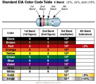
9 Each resistor has a power rating, which is the amount of energy per second that can be safely dissipated by the resistor. The resistors that we have purchased for the kits can dissipate one-half watt. Resistors have specific values of resistance to current associated with them (nominal values). The nominal value of resistors in our kit are given in a color code standardized by the Electronics Industries Association (EIA). They have a tolerance which means how close they are to the desired manufacturing value. The resistors in our parts kit have a tolerance of 5%.
10 The box of resistors in the kit are called 5 % resistors which means each value of resistor is spaced such that there is a spacing of +/- 5% from one nominal value to the next nominal value. Values that we have are 10, 11, 12, 13, 15, 16, 18, 20, 22, and so on (you can read the full list at the back of the lab manual in Appendix A). The two digits are given by the first two colors of the code. These two digits are then multiplied by a factor (multiplier). The difference between the color code for a 10 ohm resistor and a10 mega ohm resistor depends on the 3 rd color band in the color code.
11
12 Note that the color bands are somewhat skewed on the surface of the resistor. So the first band that starts closest to the lead or the end of the resistor, is the first band of the nominal value. First 2 bands are the two digits for the numeral value of the resistor (10 through 91). The third band tells you the multiplier and the 4 th band on the resistor is the tolerance value. All of our resistors are 5%, which means that the 4 th band will always be gold.
13 When you read off the values, the first 2 bands form a number between 10 and 91 and that 10 through 91 is then multiplied by the third band. If you happen to have a orange black orange for your first through third bands, the value of the resistor is 30 x 10 3 ohms or, as is more traditionally written, 30 kw. If the color were blue red yellow for the first through third bands, the resistor would be 62 x 10 4 ohm resistor (620 kw or 0.62 MW).

14 Resistance measurements are made by connecting the DMM probes across the resistor when no voltage is applied to the resistor - the ANDY board power must be off. Either place the tips of your probes at the two ends of the resistor, holding the resistor against the tips with your hands or use either the IC hooks or alligator clip probes to clamp the ends of the probe to the ends of the resistor. or Place the resistor into the breadboard (select two holes that are not connected by the metal strip under the breadboard), then insert a short length of wire that has been connected to the cables with the probe tips, the IC hooks, or alligator clips into adjacent holes on the breadboard to make the measurement across the component. Again, set the scale to the maximum and then decrease the scale until you have obtained the highest resolution measurement. Resistance measurements should not be made on resistors that are wired into a circuit as the measurement will also include the effect of the other components in the circuit. The measurement shown on the right may not be correct if the black and red wires are connected to other components.

15 The digital multimeter that we have can make AC (alternating current) and DC (direct circuit) measurements of voltage. In Experiment 3, DC measurements are required. Place the banana jacks into the DMM such that the red cable is connected into the V/W/T plug and the black cable is connected into the COM plug. Move the dial to, which selects a DC voltage measurement. Initially set the scale to the maximum and then reduce it until you obtain the highest resolution measurement (i.e., right before you reach an overflow condition. There are hotlinks in the report template for Experiment 3 with video demonstrations on how to perform the voltage measurements.

16 Two other types of probe tips IC hooks/mini-grabbers, which can be used to attached to wires and the leads on components Shown on the upper right Alligator clips, which can clamp onto wires, components, and grounds. However, they have larger uninsulated metal tips that can easily short to other parts of the circuit so use with caution. Shown on the lower right

17 Voltage measurements are made by connecting the probes to two points in the circuit with the power to the ANDY board on and all components are wired into the circuit including ground. The measurements can be: Between the voltage supply and ground to determine the actual value of the voltage supplied to the circuit. Across a single resistor to determine the voltage drop across it. From a node to ground to determine the node voltage, which should match the expected value from PSpice. Across any two nodes to determine the voltage difference between the two node voltages.

18 The red probe on the DMM must be moved from the V/W/T plug to the 10A or ma plug. Best practice is to move it first to the 10A plug. However, none of our circuits should ever have more than 100 ma flowing through them at any point in time. Therefore, it is acceptable if you connect the red probe directly into the ma plug. The black probe remains in the COM plug. Select the range for DC current measurements. As usual, work your way from the maximum range to the lowest possible to obtain the highest resolution measurement
19 Current must flow into the DMM for the measurement to be made. Therefore, you must break the circuit at the point where you want to measure the current and insert your DMM into the circuit. For example, to measure the current flowing through R1, you must break the circuit immediately after R1, before it connects to R2. Insert the current meter into the circuit and then measure the value of the current. Note the black probe on the current meter is connected to R2, which is where you expect the current to be flowing towards as it leaves R1, based upon the position of the arrow head in the upper diagram. I?


20 Generally, the red probe is connected to the side of the circuit that has the voltage supply attached and the black probe is connected to the side of the circuit that has the ground connection. If the placement of the red and black probes are switched, the magnitude of the current measurement will remain the same, but the sign will be negative.
21 The DMM can be damaged if: A voltage measurement is made while the red probe at the DMM is connected to either the 10A or ma plug. Subsequent voltage measurements may be made accurately after the probe is moved, but the current measurements will likely all be 0A. The fuse on the current measurement side of the DMM should be replaced. Instructions on how to do this are posted at AC voltage or current range (V~ or A~) is selected instead of the DC range. The measurement displayed will be zero. The fuse on the voltage measurement side of the DMM may need to be replace if subsequent measurements are always 0 (doesn t matter what type of measurement). A resistance measurement is made while the resistor is connected to a circuit with the power on. The fuse on the voltage measurement side of the DMM may need to be replace if subsequent measurements are always 0 (doesn t matter what type of measurement). Note: There are 5 replacement fuses in the parts kit. Blowing the fuse on the current measurement side happens frequently. Be careful!!! If you run out of fuses, Radio Shack, Lowes, Ace Hardware, etc. usually carry the same type of fuse.

22 Schematic Construction
23 Never make a connection between the voltage supply and ground directly to complete the circuit. This is done internally on the ANDY board in the printed circuit board (PCB the green area with the traces). Therefore, point C and point B shown on the circuit schematic in the lab manual are actually physically the same place; no wire is placed between ground and the +9V supply. When you construct the circuit in Experiment 3, Connect a wire from the +9 volt supply from the ANDY board to one of the red rows on the breadboard. Connect a wire from the ground on the ANDY board to one of the blue rows on the breadboard. Wire the resistors, R1 and R2, in series. Use a wire jumper to connect the +9V supply from the red row to one end of R1. Use a wire jumper to connect the ground from the blue row to one end of R2. Plug in the ANDY board to activate the board. You are now ready to make the voltage and current measurements described in the Experimental Procedure.
The Art of Electrical Measurements
 The Art of Electrical Measurements Purpose: Introduce fundamental electrical test and measurement tools and the art of making electrical measurements. Equipment Required Prelab 1 Digital Multimeter 1 -
HANDS-ON LAB INSTRUCTION SHEETS MODULE
 HANDS-ON LAB INSTRUCTION SHEETS MODULE 1 MEASURING RESISTANCE AND VOLTAGE NOTES: 1) Each student will be assigned to a unique Lab Equipment number MS01-MS30 which will match to a Tool Kit and a Radio Shack
Experiment 1: Breadboard Basics
 Experiment 1: Breadboard Basics Developers Objectives Estimated Time for Completion KM Lai, JB Webb, and RW Hendricks The objective of this experiment is to measure and to draw the electrical connections
II. Experimental Procedure
 Ph 122 July 27, 2006 Ohm's Law http://www.physics.sfsu.edu/~manuals/ph122/ I. Theory In this lab we will make detailed measurements on one resistor to see if it obeys Ohm's law. We will also verify the
Aim: To learn the resistor color codes and building a circuit on a BreadBoard. Equipment required: Resistances, millimeter, power supply
 Understanding the different components Aim: To learn the resistor color codes and building a circuit on a BreadBoard Equipment required: Resistances, millimeter, power supply Resistors are color coded
EET 150 Introduction to EET Lab Activity 1 Resistor Color Codes and Resistor Value Measurement
 Required Parts, Software and Equipment Parts 20 assorted 1/4 watt resistors 5% tolerance Equipment Required Solderless Experimenters' Board Digital Multimeter Optional Alligator clip leads hookup wire
Breadboard Primer. Experience. Objective. No previous electronics experience is required.
 Breadboard Primer Experience No previous electronics experience is required. Figure 1: Breadboard drawing made using an open-source tool from fritzing.org Objective A solderless breadboard (or protoboard)
Experiment 2. Ohm s Law. Become familiar with the use of a digital voltmeter and a digital ammeter to measure DC voltage and current.
 Experiment 2 Ohm s Law 2.1 Objectives Become familiar with the use of a digital voltmeter and a digital ammeter to measure DC voltage and current. Construct a circuit using resistors, wires and a breadboard
Experiment 3. Ohm s Law. Become familiar with the use of a digital voltmeter and a digital ammeter to measure DC voltage and current.
 Experiment 3 Ohm s Law 3.1 Objectives Become familiar with the use of a digital voltmeter and a digital ammeter to measure DC voltage and current. Construct a circuit using resistors, wires and a breadboard
1-1. Kirchoff s Laws A. Construct the circuit shown below. R 1 =1 kω. = 2.7 kω R 3 R 2 5 V
 Physics 310 Lab 1: DC Circuits Equipment: Digital Multimeter, 5V Supply, Breadboard, two 1 kω, 2.7 kω, 5.1 kω, 10 kω, two, Decade Resistor Box, potentiometer, 10 kω Thermistor, Multimeter Owner s Manual
EGR Laboratory 1 - Introduction to Circuit Analysis
 EGR 215 Laboratory 1 Introduction to Circuit Analysis Authors D. Wilson, R.D. Christie, W.R. Lynes, K.F. Böhringer, M. Ostendorf of the University of Washington Objectives At the end of this lab, you will
Laboratory 2. Lab 2. Instrument Familiarization and Basic Electrical Relations. Required Components: 2 1k resistors 2 1M resistors 1 2k resistor
 Laboratory 2 nstrument Familiarization and Basic Electrical Relations Required Components: 2 1k resistors 2 1M resistors 1 2k resistor 2.1 Objectives This exercise is designed to acquaint you with the
Group: Names: Resistor Band Colors Measured Value ( ) R 1 : 1k R 2 : 1k R 3 : 2k R 4 : 1M R 5 : 1M
 R 1 : 1k R 2 : 1k R 3 : 2k R 4 : 1M R 5 : 1M") 2.4 Laboratory Procedure / Summary Sheet Group: Names: (1) Select five separate resistors whose nominal values are listed below. Record the band colors for each resistor in the table below. Then connect
2.4 Laboratory Procedure / Summary Sheet Group: Names: (1) Select five separate resistors whose nominal values are listed below. Record the band colors for each resistor in the table below. Then connect
Introduction to the Laboratory
 Memorial University of Newfoundland Department of Physics and Physical Oceanography Physics 2055 Laboratory Introduction to the Laboratory The purpose of this lab is to introduce you to some of the equipment
Laboratory Equipment Instruction Manual 2011
 University of Toronto Department of Electrical and Computer Engineering Instrumentation Laboratory GB341 Laboratory Equipment Instruction Manual 2011 Page 1. Wires and Cables A-2 2. Protoboard A-3 3. DC
AME140 Lab #2 INTRODUCTION TO ELECTRONIC TEST EQUIPMENT AND BASIC ELECTRONICS MEASUREMENTS
 INTRODUCTION TO ELECTRONIC TEST EQUIPMENT AND BASIC ELECTRONICS MEASUREMENTS The purpose of this document is to guide students through a few simple activities to increase familiarity with basic electronics
Sept 13 Pre-lab due Sept 12; Lab memo due Sept 19 at the START of lab time, 1:10pm
 Sept 13 Pre-lab due Sept 12; Lab memo due Sept 19 at the START of lab time, 1:10pm EGR 220: Engineering Circuit Theory Lab 1: Introduction to Laboratory Equipment Pre-lab Read through the entire lab handout
Lab 3 DC CIRCUITS AND OHM'S LAW
 43 Name Date Partners Lab 3 DC CIRCUITS AND OHM'S LAW AMPS + - VOLTS OBJECTIVES To learn to apply the concept of potential difference (voltage) to explain the action of a battery in a circuit. To understand
Physics 323. Experiment # 1 - Oscilloscope and Breadboard
 Physics 323 Experiment # 1 - Oscilloscope and Breadboard Introduction In order to familiarise yourself with the laboratory equipment, a few simple experiments are to be performed. References: XYZ s of
Revision: Jan 29, E Main Suite D Pullman, WA (509) Voice and Fax
 Voice and Fax") Revision: Jan 29, 2011 215 E Main Suite D Pullman, WA 99163 (509) 334 6306 Voice and Fax Overview The purpose of this lab assignment is to provide users with an introduction to some of the equipment which
Revision: Jan 29, 2011 215 E Main Suite D Pullman, WA 99163 (509) 334 6306 Voice and Fax Overview The purpose of this lab assignment is to provide users with an introduction to some of the equipment which
EK307 Introduction to the Lab
 EK307 Introduction to the Lab Learning to Use the Test Equipment Laboratory Goal: Become familiar with the test equipment in the electronics laboratory (PHO105). Learning Objectives: Voltage source and
CECS LAB 4 Prototyping Series and Parallel Resistors
 NAME: POSSIBLE POINTS: 10 NAME: NAME: DIRECTIONS: We are going to step through the entire process from conceptual to a physical prototype for the following resistor circuit. STEP 1 - CALCULATIONS: Calculate
UNIVERSITY OF NORTH CAROLINA AT CHARLOTTE Department of Electrical and Computer Engineering
 UNIVERSITY OF NORTH CAROLINA AT CHARLOTTE Department of Electrical and Computer Engineering EXPERIMENT 2 BASIC CIRCUIT ELEMENTS OBJECTIVES The purpose of this experiment is to familiarize the student with
LAB 1 AN EXAMPLE MECHATRONIC SYSTEM: THE FURBY
 LAB 1 AN EXAMPLE MECHATRONIC SYSTEM: THE FURBY Objectives Preparation Tools To see the inner workings of a commercial mechatronic system and to construct a simple manual motor speed controller and current
ENGR 1181 Lab 3: Circuits
 ENGR 1181 Lab 3: Circuits - - Lab Procedure - Report Guidelines 2 Overview of Circuits Lab: The Circuits Lab introduces basic concepts of electric circuits such as series and parallel circuit, used in
Laboratory 2 (drawn from lab text by Alciatore)
") Laboratory 2 (drawn from lab text by Alciatore) Instrument Familiarization and Basic Electrical Relations Required Components: 2 1k resistors 2 1M resistors 1 2k resistor Objectives This exercise is designed
Laboratory 2 (drawn from lab text by Alciatore) Instrument Familiarization and Basic Electrical Relations Required Components: 2 1k resistors 2 1M resistors 1 2k resistor Objectives This exercise is designed
ENGR 120 LAB #2 Electronic Tools and Ohm s Law
 ENGR 120 LAB #2 Electronic Tools and Ohm s Law Objectives Understand how to use a digital multi-meter, power supply and proto board and apply that knowledge to constructing circuits to demonstrate ohm
Lab 1: DC Measurements (R, V, I)
") Lab 1: DC Measurements (R, V, I) Introduction Resistors are the most common component found in all electrical and electronic circuits. Resistors are found in many shapes, sizes, and values. The most common
Lab 1: DC Measurements (R, V, I) Introduction Resistors are the most common component found in all electrical and electronic circuits. Resistors are found in many shapes, sizes, and values. The most common
EET140/3 ELECTRIC CIRCUIT I
 SCHOOL OF ELECTRICAL SYSTEM ENGINEERING UNIVERSITI MALAYSIA PERLIS EET140/3 ELECTRIC CIRCUIT I MODULE 1 PART I: INTRODUCTION TO BASIC LABORATORY EQUIPMENT PART II: OHM S LAW PART III: SERIES PARALEL CIRCUIT
Current, resistance, and Ohm s law
 Current, resistance, and Ohm s law Apparatus DC voltage source set of alligator clips 2 pairs of red and black banana clips 3 round bulb 2 bulb sockets 2 battery holders or 1 two-battery holder 2 1.5V
Materials: resistors: (5) 1 kω, (4) 2 kω, 2.2 kω, 3 kω, 3.9 kω digital multimeter (DMM) power supply w/ leads breadboard, jumper wires
 1 kω, (4) 2 kω, 2.2 kω, 3 kω, 3.9 kω digital multimeter (DMM) power supply w/ leads breadboard, jumper wires") Lab 6: Electrical Engineering Technology References: 1. Resistor (electronic) color code: http://en.wikipedia.org/wiki/electronic_color_code 2. Resistor color code tutorial: http://www.michaels-electronics-lessons.com/resistor-color-code.html
Lab 6: Electrical Engineering Technology References: 1. Resistor (electronic) color code: http://en.wikipedia.org/wiki/electronic_color_code 2. Resistor color code tutorial: http://www.michaels-electronics-lessons.com/resistor-color-code.html
General Lab Notebook instructions (from syllabus)
") Physics 310 Lab 1: DC Circuits Equipment: Digital Multimeter, 5V Supply, Breadboard, two 1 k, 2.7 k, 5.1 k, 10 k, two Decade Resistor Box, potentiometer, 10 k Thermistor, Multimeter Owner s Manual General
Physics 310 Lab 1: DC Circuits Equipment: Digital Multimeter, 5V Supply, Breadboard, two 1 k, 2.7 k, 5.1 k, 10 k, two Decade Resistor Box, potentiometer, 10 k Thermistor, Multimeter Owner s Manual General
Digital Electronics & Chip Design
 Digital Electronics & Chip Design Lab Manual I: The Utility Board 1999 David Harris The objective of this lab is to assemble your utility board. This board, containing LED displays, switches, and a clock,
PHY 132 LAB : Ohm s Law
 PHY 132 LAB : Ohm s Law Introduction: In this lab, we look at the concepts of electrical resistance and resistivity. Text Reference: Wolfson 27:2-3. Special equipment notes: 1. Note the tips on wiring
+ A Supply B. C Load D
 17 E7 E7.1 OHM'S LAW AND RESISTANCE NETWORKS OBJECT The objects of this experiment are to determine the voltage-current relationship for a resistor and to verify the series and parallel resistance formulae.
ECE 2274 Lab 2. Your calculator will have a setting that will automatically generate the correct format.
 ECE 2274 Lab 2 Forward (DO NOT TURN IN) You are expected to use engineering exponents for all answers (p,n,µ,m, N/A, k, M, G) and to give each with a precision between one and three leading digits and
Lab 2.4 Arduinos, Resistors, and Circuits
 Lab 2.4 Arduinos, Resistors, and Circuits Objectives: Investigate resistors in series and parallel and Kirchoff s Law through hands-on learning Get experience using an Arduino hat you need: Arduino Kit:
ECE 2274 Lab 2 (Network Theorems)
") ECE 2274 Lab 2 (Network Theorems) Forward (DO NOT TURN IN) You are expected to use engineering exponents for all answers (p,n,µ,m, N/A, k, M, G) and to give each with a precision between one and three
ECE 2274 Lab 2 (Network Theorems) Forward (DO NOT TURN IN) You are expected to use engineering exponents for all answers (p,n,µ,m, N/A, k, M, G) and to give each with a precision between one and three
EECS40 Lab Introduction to Lab: Guide
 Aschenbach, Konrad Muthuswamy, Bharathwaj EECS40 Lab Introduction to Lab: Guide Objective The student will use the following circuit elements and laboratory equipment to make basic circuit measurements:
Lab 2 Electrical Safety, Breadboards, Using a DMM
 Lab 2 Electrical Safety, Breadboards, Using a DMM Objectives concepts 1. Safety hazards related to household electricity and electronics equipment 2. Differences between schematic and breadboard representations
LAB MODULES. MSCI 222C Introduction to Electronics. Charles Rubenstein, Ph. D. Professor of Engineering & Information Science
 MSCI 222C Introduction to Electronics Charles Rubenstein, Ph. D. Professor of Engineering & Information Science LAB MODULES Copyright 2015-2019 C.P.Rubenstein Electronics Hands-On Lab - Module 01 MSCI
B EE Laboratory 1 - Introduction to Circuit Analysis
 Page 1 B EE 215 Introduction to Circuit Analysis Authors D. Wilson, R.D. Christie, W.R. Lynes, K.F. Böhringer, M. Ostendorf Objectives At the end of this lab, you will be able to: Check continuity with
DC CIRCUITS AND OHM'S LAW
 July 15, 2008 DC Circuits and Ohm s Law 1 Name Date Partners DC CIRCUITS AND OHM'S LAW AMPS - VOLTS OBJECTIVES OVERVIEW To learn to apply the concept of potential difference (voltage) to explain the action
Resistance. Department of Physics & Astronomy Texas Christian University, Fort Worth, TX. April 23, 2013
 Resistance Department of Physics & Astronomy Texas Christian University, Fort Worth, TX April 23, 2013 1 Introduction Electrical resistance is a measure of how much an object opposes (or resists) the flow
Lab Equipment EECS 311 Fall 2009
 Lab Equipment EECS 311 Fall 2009 Contents Lab Equipment Overview pg. 1 Lab Components.. pg. 4 Probe Compensation... pg. 8 Finite Instrumentation Impedance. pg.10 Simulation Tools..... pg. 10 1 - Laboratory
Pacific Antenna Easy TR Switch
 Pacific Antenna Easy TR Switch Kit Description The Easy TR Switch is an RF sensing circuit with a double pole double throw relay that can be used to automatically switch an antenna between a separate receiver
Simple Circuits Experiment
 Physics 8.02T 1 Fall 2001 Simple Circuits Experiment Introduction Our world is filled with devices that contain electrical circuits in which various voltage sources cause currents to flow. We use radios,
I. Objectives Upon completion of this experiment, the student should be able to: Ohm s Law
 EENG-201 Experiment # 1 Series Circuit and Parallel Circuits I. Objectives Upon completion of this experiment, the student should be able to: 1. ead and use the resistor color code. 2. Use the digital
Manual Version July 2007
 Manual Version 1.2 - July 2007 Page 1 Table of Contents Section1: M3 Phono Board Build...3 Phono Board Parts List...3 Preparation...4 Fitting the Valve Bases...6 Installing the Resistors...7 Starting the
Pacific Antenna - Easy TR Switch
 Pacific Antenna - Easy TR Switch Kit Description The Easy TR Switch is an RF sensing switch that can be used to switch an antenna between a receiver and transmitter. It also has a second switched pair
HANDS-ON LAB INSTRUCTION SHEET MODULE 3 CAPACITORS, TIME CONSTANTS AND TRANSISTOR GAIN
 HANDS-ON LAB INSTRUCTION SHEET MODULE 3 CAPACITORS, TIME CONSTANTS AND TRANSISTOR GAIN NOTES: 1) To conserve the life of the Multimeter s 9 volt battery, be sure to turn the meter off if not in use for
Laboratory 1 page 1 of 13
 Laboratory 1 page 1 of 13 Laboratory 1 Using the Meter, Breadboard, and Soldering Iron Introduction Welcome to the Bio Electronics Laboratory (BEL) located in B10 Benedum Hall. In this first lab assignment,
Electric Circuit Experiments
 Electric Circuit Experiments 1. Using the resistor on the 5-resistor block, vary the potential difference across it in approximately equal increments for eight different values (i.e. use one to eight D-
ECE 2274 Lab 1 (Intro)
") ECE 2274 Lab 1 (Intro) Richard Dumene: Spring 2018 Revised: Richard Cooper: Spring 2018 Forward (DO NOT TURN IN) The purpose of this lab course is to familiarize you with high-end lab equipment, and train
ECE 2274 Lab 1 (Intro) Richard Dumene: Spring 2018 Revised: Richard Cooper: Spring 2018 Forward (DO NOT TURN IN) The purpose of this lab course is to familiarize you with high-end lab equipment, and train
V (in volts) = voltage applied to the circuit, I (in amperes) = current flowing in the circuit, R (in ohms) = resistance of the circuit.
 = voltage applied to the circuit, I (in amperes) = current flowing in the circuit, R (in ohms) = resistance of the circuit.") OHM S LW OBJECTIES: PRT : 1) Become familiar with the use of ammeters and voltmeters to measure DC voltage and current. 2) Learn to use wires and a breadboard to build circuits from a circuit diagram.
OHM S LW OBJECTIES: PRT : 1) Become familiar with the use of ammeters and voltmeters to measure DC voltage and current. 2) Learn to use wires and a breadboard to build circuits from a circuit diagram.
Lab 4 OHM S LAW AND KIRCHHOFF S CIRCUIT RULES
 57 Name Date Partners Lab 4 OHM S LAW AND KIRCHHOFF S CIRCUIT RULES AMPS - VOLTS OBJECTIVES To learn to apply the concept of potential difference (voltage) to explain the action of a battery in a circuit.
IR add-on module circuit board assembly - Jeffrey La Favre January 27, 2015
 IR add-on module circuit board assembly - Jeffrey La Favre January 27, 2015 1 2 For the main circuits of the line following robot you soldered electronic components on a printed circuit board (PCB). The
OHM'S LAW AND RESISTANCE NETWORKS OBJECT
 17 E7 E7.1 OHM'S LAW AND RESISTANCE NETWORKS OBJECT The objects of this experiment are to determine the voltage-current relationship for a resistor and to verify the series and parallel resistance formulae.
EE 210: CIRCUITS AND DEVICES
 EE 210: CIRCUITS AND DEVICES LAB #3: VOLTAGE AND CURRENT MEASUREMENTS This lab features a tutorial on the instrumentation that you will be using throughout the semester. More specifically, you will see
EE 201 Lab 1. Meters, DC sources, and DC circuits with resistors
 Meters, DC sources, and DC circuits with resistors 0. Prior to lab Read through the lab and do as many of the calculations as possible. Then, learn how to determine resistance values using the color codes.
EE283 Laboratory Exercise 1-Page 1
 EE283 Laboratory Exercise # Basic Circuit Concepts Objectives:. To become familiar with the DC Power Supply unit, analog and digital multi-meters, fixed and variable resistors, and the use of solderless
Industrial Electricity
 Industrial Electricity Name DUE //7 or //7 (Your next lab day) Prelab: efer to the tables on Page 5. Show work neatly and completely on separate paper for any entry labeled calculated. You do not need
DC Circuits, Ohm's Law and Multimeters Physics 246
 DC Circuits, Ohm's Law and Multimeters Physics 246 Theory: In this lab we will learn the use of multimeters, verify Ohm s law, and study series and parallel combinations of resistors and capacitors. For
Engineering Laboratory Exercises (Electric Circuits Module) Prepared by
 Prepared by") Engineering 1040 Laboratory Exercises (Electric Circuits Module) Prepared by Eric W. Gill FALL 2008 2 EXP 1040-EL1 VOLTAGE, CURRENT, RESISTANCE AND POWER PURPOSE To (i) investigate the relationship between
Engineering 1040 Laboratory Exercises (Electric Circuits Module) Prepared by Eric W. Gill FALL 2008 2 EXP 1040-EL1 VOLTAGE, CURRENT, RESISTANCE AND POWER PURPOSE To (i) investigate the relationship between
ECE 53A: Fundamentals of Electrical Engineering I
 ECE 53A: Fundamentals of Electrical Engineering I Laboratory Assignment #1: Instrument Operation, Basic Resistor Measurements and Kirchhoff s Laws Fall 2007 General Guidelines: - Record data and observations
AC/DC ELECTRONICS LABORATORY
 Includes Teacher's Notes and Typical Experiment Results Instruction Manual and Experiment Guide for the PASCO scientific Model EM-8656 012-05892A 1/96 AC/DC ELECTRONICS LABORATORY 1995 PASCO scientific
Oregon State University Lab Session #1 (Week 3)
") Oregon State University Lab Session #1 (Week 3) ENGR 201 Electrical Fundamentals I Equipment and Resistance Winter 2016 EXPERIMENTAL LAB #1 INTRO TO EQUIPMENT & OHM S LAW This set of laboratory experiments
Oregon State University Lab Session #1 (Week 3) ENGR 201 Electrical Fundamentals I Equipment and Resistance Winter 2016 EXPERIMENTAL LAB #1 INTRO TO EQUIPMENT & OHM S LAW This set of laboratory experiments
How to Wire an Inverting Amplifier Circuit
 How to Wire an Inverting Amplifier Circuit Figure 1: Inverting Amplifier Schematic Introduction The purpose of this instruction set is to provide you with the ability to wire a simple inverting amplifier
Laboratory Project 1a: Power-Indicator LED's
 2240 Laboratory Project 1a: Power-Indicator LED's Abstract-You will construct and test two LED power-indicator circuits for your breadboard in preparation for building the Electromyogram circuit in Lab
Figure 1. CheapBot Smart Proximity Detector
 The CheapBot Smart Proximity Detector is a plug-in single-board sensor for almost any programmable robotic brain. With it, robots can detect the presence of a wall extending across the robot s path or
Pacific Antenna Easy Transmitter Kit
 Pacific Antenna Easy Transmitter Kit Introduction The Easy Transmitter kit from qrpkits.com provides a crystal controlled transmitter with VXO tuning. The circuit consists of a N3904 based crystal oscillator
Electric Circuit I Lab Manual Session # 2
 Electric Circuit I Lab Manual Session # 2 Name: ----------- Group: -------------- 1 Breadboard and Wiring Objective: The objective of this experiment is to be familiar with breadboard and connection made
SoftRock v5.0 Builder s Notes. December 12, Building a QSD Kit
 SoftRock v5.0 Builder s Notes December 12, 2005 Building a QSD Kit Be sure to use a grounded tip soldering iron in building the QSD board. The soldering iron needs to have a small tip, (0.05-0.1 inch diameter),
PAT-4 POWER SUPPLY ASSEMBLY MANUAL Rev B Version
 PAT-4 POWER SUPPLY ASSEMBLY MANUAL Rev B Version 2013 AkitikA, LLC All rights reserved Revision Bp01 November 3, 2013 Page 1 of 16 Table of Contents Table of Contents... 2 Table of Figures... 2 Section
EECE 2413 Electronics Laboratory
 EECE 2413 Electronics Laboratory Lab #2: Diode Circuits Goals In this lab you will become familiar with several different types of pn-junction diodes. These include silicon and germanium junction diodes,
Lab 13 AC Circuit Measurements
 Lab 13 AC Circuit Measurements Objectives concepts 1. what is impedance, really? 2. function generator and oscilloscope 3. RMS vs magnitude vs Peak-to-Peak voltage 4. phase between sinusoids skills 1.
Lab #1 Help Document. This lab will be completed in room 335 CTB. You will need to partner up for this lab in groups of two.
 Lab #1 Help Document This help document will be structured as a walk-through of the lab. We will include instructions about how to write the report throughout this help document. This lab will be completed
Lab #6: Op Amps, Part 1
 Fall 2013 EELE 250 Circuits, Devices, and Motors Lab #6: Op Amps, Part 1 Scope: Study basic Op-Amp circuits: voltage follower/buffer and the inverting configuration. Home preparation: Review Hambley chapter
Course materials and schedule are at. positron.hep.upenn.edu/p364
 Physics 364, Fall 2014, Lab #1 Name: (using breadboards; measuring voltage, current, and resistance) Wednesday, August 27 (section 401); Thursday, August 28 (section 402) Course materials and schedule
Building the Toothpick Audio CW Filter
 Building the Toothpick Audio CW Filter Introduction The toothpick is a simple variable bandpass audio filter designed to compliment the Splinter QRPp Trans-Receiver. The filter also contains an audio amplifier
Pre-Laboratory Assignment
 Measurement of Electrical Resistance and Ohm's Law PreLaboratory Assignment Read carefully the entire description of the laboratory and answer the following questions based upon the material contained
Ohm s and Kirchhoff s Circuit Laws. Abstract. Introduction and Theory. EE 101 Spring 2006 Date: Lab Section #: Lab #2
 EE 101 Spring 2006 Date: Lab Section #: Lab #2 Name: Ohm s and Kirchhoff s Circuit Laws Abstract Rev. 20051222JPB Partner: Electrical circuits can be described with mathematical expressions. In fact, it
Lab 4 - Operational Amplifiers 1 Gain ReadMeFirst
 Lab 4 - Operational Amplifiers 1 Gain ReadMeFirst Lab Summary There are three basic configurations for operational amplifiers. If the amplifier is multiplying the amplitude of the signal, the multiplication
Physics 3330 Experiment #2 Fall DC techniques, dividers, and bridges
 Physics 3330 Experiment #2 Fall 2002 DC techniques, dividers, and bridges Purpose You will gain a familiarity with the circuit board and work with a variety of DC techniques, including voltage dividers,
CSE208W Lecture #1 Notes Barry E. Mapen
 CSE208W Lecture #1 Notes Barry E. Mapen Parts Kit Before we start, let s take a look at the parts kit. Open you kit when you have some time and start to learn what the pieces are inside of that kit. Be
LAB 1: Familiarity with Laboratory Equipment (_/10)
") LAB 1: Familiarity with Laboratory Equipment (_/10) PURPOSE o gain familiarity with basic laboratory equipment oscilloscope, oscillator, multimeter and electronic components. EQUIPMEN (i) Oscilloscope
LAB 1: Familiarity with Laboratory Equipment (_/10) PURPOSE o gain familiarity with basic laboratory equipment oscilloscope, oscillator, multimeter and electronic components. EQUIPMEN (i) Oscilloscope
University of Jordan School of Engineering Electrical Engineering Department. EE 204 Electrical Engineering Lab
 University of Jordan School of Engineering Electrical Engineering Department EE 204 Electrical Engineering Lab EXPERIMENT 1 MEASUREMENT DEVICES Prepared by: Prof. Mohammed Hawa EXPERIMENT 1 MEASUREMENT
Electronics Technology and Robotics I Week 5 Resistors and Potentiometers
 Electronics Technology and Robotics I Week 5 Resistors and Potentiometers Administration: o Prayer o Turn in quiz o Using two switches, design a circuit that correspond to an AND gate. Resistors: o Function:
BENCH METER Model>9803. Wavecom Instruments
 BENCH METER Model>9803 Wavecom Instruments 1 Basic Information This guide provides basic instructions for operating the Mastech M9803R Bench Digital Multimeter. The M9803R provides these features: Multiple
Assembly Instructions
 Assembly Instructions For the SSQ-2F 3.1 MHz Rife Controller Board Kit v1.41 Manual v1.00 2012 by Ralph Hartwell Spectrotek Services GENERAL ASSEMBLY INSTRUCTIONS Arrange for a clean work surface with
Give one or two examples of electrical devices that you have personally noticed getting warm when they are turned on.
 Resistors We begin by learning how to read the values of resistors and to measure the values using a digital multimeter (DMM). Resistors are the most common and simplest electrical component. In an electrical
EE1020 Diodes and Resistors in Electrical Circuits Spring 2018
 PURPOSE The purpose of this project is for you to become familiar with some of the language, parts, and tools used in electrical engineering. You will also be introduced to some simple rule and laws. MATERIALS
Lab 5 Kirchhoff s Laws and Superposition
 Lab 5 Kirchhoff s Laws and Superposition In this lab, Kirchhoff s laws will be investigated using a more complex circuit than in the previous labs. Two voltage sources and seven resistors are included
Bill of Materials: PWM Stepper Motor Driver PART NO
 PWM Stepper Motor Driver PART NO. 2183816 Control a stepper motor using this circuit and a servo PWM signal from an R/C controller, arduino, or microcontroller. Onboard circuitry limits winding current,
Appendix A: Laboratory Equipment Manual
 Appendix A: Laboratory Equipment Manual 1. Introduction: This appendix is a manual for equipment used in experiments 1-8. As a part of this series of laboratory exercises, students must acquire a minimum
HANDS-ON ACTIVITY 4 BUILDING SERIES AND PARALLEL CIRCUITS BACKGROUND WIRING DIRECTIONS
 ACTIVITY 4 BUILDING SERIES AND PARALLEL CIRCUITS BACKGROUND Make sure you read the background in Activity 3 before doing this activity. WIRING DIRECTIONS Materials per group of two: one or two D-cells
PHYS Contemporary Physics Laboratory Laboratory Exercise: LAB 01 Resistivity, Root-mean-square Voltage, Potentiometer (updated 1/25/2017)
") PHYS351001 Contemporary Physics Laboratory Laboratory Exercise: LAB 01 Resistivity, Root-mean-square Voltage, Potentiometer (updated 1/25/2017) PART I: SOME FUNDAMENTAL CONCEPTS: 1. Limits on accuracy
PHYS351001 Contemporary Physics Laboratory Laboratory Exercise: LAB 01 Resistivity, Root-mean-square Voltage, Potentiometer (updated 1/25/2017) PART I: SOME FUNDAMENTAL CONCEPTS: 1. Limits on accuracy
MONO AMPLIFIER KIT ESSENTIAL INFORMATION. Version 3.0 CREATE YOUR OWN SPEAKER DOCK WITH THIS
 ESSENTIAL INFORMATION BUILD INSTRUCTIONS CHECKING YOUR PCB & FAULT-FINDING MECHANICAL DETAILS HOW THE KIT WORKS CREATE YOUR OWN SPEAKER DOCK WITH THIS MONO AMPLIFIER KIT Version 3.0 Build Instructions
Circuit Analysis Laboratory Workbook
 Circuit Analysis Laboratory Workbook Synthesis Lectures on Electrical Engineering Editor Richard C. Dorf, University of California, Davis Circuit Analysis Laboratory Workbook Teri L. Piatt and Kyle E.
Easy Transmitter. Support ETX_REV5_Manual V2.7 Revised
 Easy Transmitter Introduction The Easy Transmitter kit from qrpkits.com provides a basic, crystal controlled transmitter with VXO tuning to provide a small tuning range around the crystal frequency. It