Assembly Instructions for a Double Climbing Frame
|
|
|
- Camron Crawford
- 5 years ago
- Views:
Transcription

1 Assembly Instructions for a Double Climbing Frame Step 1: Lay out both bases with 8ft of spacing between them (See Diagram Below) Once you are happy with the position of each base, remove bases and follow instruction steps 1-8 on assembly instructions for the 5ft Climbing Frame pg. 1
2 Assembly instructions for 6 foot double climbing frame Materials provided: 8 x 10ft posts cut at an angle of 40 degrees (for main towers) 2 x 10ft posts cut at an angle of 60 degrees (with the top already prepared for the swing pole) 1 x 10ft post for the swing pole 4 x 1571mm posts 4 x 6ftx4ft fence panels 8 x v boards for roof module (4 small and 4 larger ones) 1 x steps 1 x 1755mm x 1755mm base 5 x 1571mm 3 x1 ½ timber 2 x 1571mm 3 x3 timber 8 x 1755mm 3 x1 ½ timber 8 sets of railings Slats for Rope Bridge 2 x 2600mm 3 x3 timbers 1 x rock wall 10ft slide Accessories (swings, grab-handles, 6 x o hooks, telescope, periscope, steering wheel, pirates wheel) Screws etc (24 x 200mm index screws, 26 x 120mm screws, 1 box 65mm decking screws, u-nails, 30 bolt cover caps) For Picnic table you will also receive the following: 20 x 1571mm 3 x1 ½ timbers 2 x 1755mm 3 x1 ½ timbers pg. 2
3 Step1: Ground Preparation (see Diagram 1) Lay out the bases in the position that you envisage them going Make sure the frames line up with each other and are no more than 8ft apart When placing the bases please ensure you allow for 6 ft clearance beyond the end of the slide and 3 ft clearance for all other modules. Once you are happy that the layout is correct, mark out clearly all 8 corners of the bases If the climbing frame is on a level surface then dig 4 holes of diameter 12 and depth 12. The tricky part is when the surface is uneven; in this case you would have to compensate for the slope by making some holes deeper than others. The easiest way is to take a spirit level and see how much the ground slopes and dig the rest of the holes accordingly. The bottom of all 4 holes need to be level Step2: Base Preparation Lay 2 of the 10ft posts that are cut at the 40% angle on a level surface Ensure the cut angle is facing the same way on both posts and that the 32mm holes (about halfway up) are facing outwards Now place the 1571mm 4 x4 post between the 2 larger posts Line up the markings as shown below pg. 3
4 Now with the 200mm index screws provided, screw the poles together on both sides, making sure the index screw is tightened into place Make a mark 900mm from the bottom of both 10ft posts Using the 1755mm 3 x1 ½ timber and using the 65mm decking screws screw the timber to the frame (this is to strengthen the H-frame structure, without this additional support at the bottom the frame will twist once it is lifted up) Using another 1755mm 3 x1 ½ timber place this on the 40 angle (on the top of the post) and screw into place using the 65mm decking screws Both of the above steps strengthen the H-frame structure, without this additional support at the top and bottom the frame will twist once it is lifted up Repeat the above steps for all the H-frames Step 3: Base assembly (requires heavy lifting, please use at least 2 people) Lift both H -frames into the holes that have been dug out in the ground Make sure the tops of these H -frames have the correct angle pointing in (to ensure that the roof will be able to rest on the tops) To ensure that the base fits into place use the 1571mm 3x1 ½ timber provided to connect the 2 H -frames together pg. 4
5 The structure should now be able to stand on it s own Lift the base and place into it s place Secure base using the 120mm screws provided, they are to be screwed directly into the base onto the 4 x4 cross posts Step 4: Side-rails assembly There are 5 open and 3 closed rails (these may be slightly different if you ve gone for a different configuration). The open ones are for the steps, slide, rope bridge and fireman s pole and the closed ones are for the 8ft rock module,8ft cargo net and swing module. They should fit tightly into place between the upright posts and on the base. The double timbers on the side-rails should be on top and the single timber should be at the bottom Secure the bottom rail to the base using decking screws pg. 5
6 Using the 120mm screws, screw through the upright post so as to tighten the top railing to the post Repeat for all the side-rails Step 5: Roof assembly (See Appendix A) Place one of the 6ftx5ft panels directly onto the ground (so that the shingled part is facing downwards) Using the v boards provided assemble the roof Lift the roof onto the climbing frame and ensure it is level before securing the roof to the top of the post using 2 x decking screws per post pg. 6
7 Step 6: Swing module assembly Lay the 2 x 10ft posts (with the ends cut off at 60 degrees) on a flat surface Place the ends together so that it forms a v-shape Using the 200mm index screws, tighten the ends together Measure down from the top of the v post 1100mm to both posts and place the 1571mm 3 x1 ½ timber across both posts and secure these into place with decking screws pg. 7
8 Place the o -hooks supplied through the holes on the remaining 4 x4 post (square on both ends) securing them using the appropriate spanner Now the tricky part. The A -frame is designed to be at a 10 degree angle (i.e it is not at 90 degrees to the surface). This is best achieved by measuring 11 ft from the end of the climbing frame to the base of the A-frame. Put the A-frame up (the 11ft away from the frame) and place the 10ft swing arm post on top of it The A-frame should be then lined up to the centre of the tower The holes on the ground should then be marked and the v -frame should be sunk into it s place so that the swing bar is level To obtain the depth of the holes place a spirit level on the swing arm and measure how much the A-frame has to be sunk into the ground. Once this is achieved, then secure both ends into place pg. 8
9 Step 7: Concreting structure Using postcrete and following the manufacturers instruction concrete all 10 posts into the ground Once dry you can continue Step 8: Rock Wall assembly The rock wall is typically made slightly longer than required to allow for slope Place the rock wall against the top of the railing Measure the amount you may have to take off the bottom of the rock wall Cut the bottom of the rock wall to ensure that it fits onto the top rail Screw the rock wall into it s place using 2 x 65mm screw per board pg. 9
10 Step 9: Cargo net assembly Place the cargo net onto the top of the railing Depending on the slope of the ground you may need to dig up some ground to ensure the cargo net is parallel to the upright posts of the tower Using the 120mm screws provided please screw the cargo net into the top rail pg. 10
11 Step 10: Fireman s pole Place the fireman s pole into it s position (ensuring that it is parallel to the post). You will see that it will be to tall to attach to the top rail Mark the position that it will go into the ground Dig a hole about 10 deep and 10 in diameter Place the fireman s pole into the hole and cut off any excess length so that the pole can be secured into the top rail Secure the climbing pole onto the top rail using 65mm decking screws supplied Concrete the pole into it s place ensuring that it remains parallel to the tower posts pg. 11

12 Step 11: Slide and steps The steps might have to cut or dug into place (depending on the slope of your surface) They are secured using decking screws Grab handles are then placed on the top of the steps The slide is secured into place using the 65mm decking supplied Step 12: Picnic Table Using the existing 1571mm 3 x1 ½ timbers that were placed at the bottom of the climbing frame add an additional 3 x 1571mm 3 x1 ½ timbers beside these to form the seating for the picnic table Measure 300mm above the seating and mark all 4 posts Using the 1755mm 3 x1 ½ timbers screw these into place so as to form straps for the table top Using 12 x 1571mm 3 x1 ½ timbers centre these so as to form the table top itself Screw these into place using the 65mm decking screw provided pg. 12

13 If you are installing a sandpit picnic table please follow these instructions: Place a 1571mm 3 x1 ½ timber on it s side on both the left and right ends of the picnic table Screw these in through the bottom using 65mm decking screw Measure the distance between the 1571mm 3 x1 ½ timbers and cut the length from a 1571mm 3 x1 ½ timber Screw these into place so as to form a rectangle on top of the existing picnic table Screw a further 2 x 1571mm 3 x1 ½ timbers (one on either side) Using the remaining 10 lengths of the 1571mm 3 x1 ½ timbers form a base solid base pg. 13

14 Step 12: Rope Bridge Using the 2.6m lengths of 3 x3 place these on the underside of the bases. They are to be placed 150mm to the left and right of the centre point of the base Screw these in using 120mm screws provided Using the 1571mm 3 x3 place these horizontally below the base as per diagram G below Drill 32mm holes on the outside of the main posts and screw these in using 120mm screws provided You are now ready to screw on the decking boards for the rope bridge and attach the rope and safety netting pg. 14


15 Photos that might be useful in building the climbing frame: pg. 15
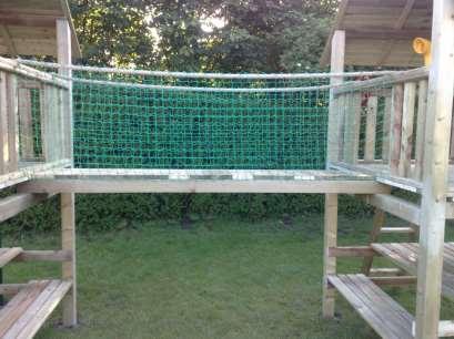

16 pg. 16
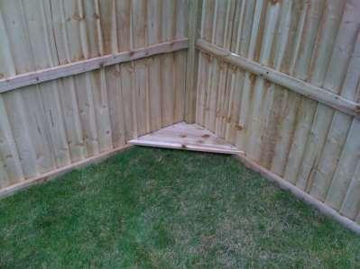
17 pg. 17
Assembly Instructions for a Double Climbing Frame
 Assembly Instructions for a Double Climbing Frame Step A: Lay out both bases with 8ft of spacing between them (See Diagram X) Once you are happy with the position of each base, remove bases and follow
The Festival Assembly Instructions
 The Festival Assembly Instructions Toll Free: 866.768.8465 Hours: 9-5 Monday-Friday EST www.homeplacestructures.com Package ships as shown CONTACT INFORMATION: HomePlace Structures 301 Commerce Drive New
Junglenastix. Instruction Manual. Technical Support: Riaan Prinsloo Do-It-Yourself Jungle Gym Kits
 Junglenastix Do-It-Yourself Jungle Gym Kits Instruction Manual Technical Support: Riaan Prinsloo 0828039217 Thank you for choosing Junglenastix as your way to make a very positive contribution to your
Greenhouse Assembly Instructions
 Greenhouse Assembly Instructions Our Help Line provides support and advice to customers of Summer Garden Buildings after ordering. For advice before you buy you can phone us free 7 days a week on 0800
Gardman Lean-to Greenhouse Assembly Instructions
 Page 1 Gardman Lean-to Greenhouse Assembly Instructions Our Help Line provides support and advice to customers of Summer Garden Buildings after ordering. For advice before you buy you can phone us free
Section 1 Safety working at height
 Contents Section 1 Safety working at height. Section 2 Hi-Step package contents & parts identification. Section 3 Assembly. Section 4 Operation. Section 5 Maintenance. Section 6 Extender package contents
Strata. urniture. Addison Instructions. Parts in the Arm Box: Parts in the Body Box: Watch our assembly videos at
 1A Watch our assembly videos at www.strataf.com/videos.html Parts in the Arm Box: Arm - Outside View Arm - Inside View Corbels x 4 1B Parts in the Body Box: Back Deck x 1 Seat Deck x 1 Back Panel x 1 with
CONSTRUCTION GUIDE 21ft Wide and 24ft Wide SHEEP HOUSE
 The Outside, Inside CONSTRUCTION GUIDE 21ft Wide and 24ft Wide SHEEP HOUSE Thank you for purchasing a Premier Sheep House. Please take the time to carefully read through this Construction Guide before
CONSTRUCTION GUIDE 27ft Wide and 30ft Wide SHEEP HOUSE
 The Outside, Inside CONSTRUCTION GUIDE 27ft Wide and 30ft Wide SHEEP HOUSE Thank you for purchasing a Premier Sheep House. Please take the time to carefully read through this Construction Guide before
Art Thatch TM Umbrella Kit Installation Guide
 Art Thatch TM Umbrella Kit Installation Guide www.artificialthatch.com (858) 643-9030 sales@artthatch.com Parts List Part # Description Name Qty. #1 Main Frame 1 #2 Small Cross Bar 8 #3 Medium Cross Bar
Residential & Industrial Fence
 Residential & Industrial Fence Assembly Instructions CONTENTS 02: OVERVIEW & CONTENTS 03: PRODUCT SPECIFICATIONS 04: GETTING STARTED 05: WALL ATTACHMENT & LINE POST ASSEMBLY 06: CORNER POST ASSEMBLY 07:
NON-ELECTRIC DOG FENCES
 NON-ELECTRIC DOG FENCES Thank you! Thank you for ordering your non-electric dog fence kit from Pet Playgrounds. In less than a day you will have your very own personal dog park installed on your property.
TELESCOPIC GATE MANUFACTURING AND INSTALLATION MANUAL.
 TELESCOPIC GATE MANUFACTURING AND INSTALLATION MANUAL. Telescopic gates have been manufactured for many years essentially in the same way they are largely today. In recent years hardware suppliers have
TREX ENHANCE RAILING (Also Applies to Trex Select Railing) Installation Instructions
 Installation Instructions") TREX ENHANCE RAILING (Also Applies to Trex Select Railing) NOTE: All Enhance Railing lengths are manufactured at CLEAR SPAN dimensions (spanning between space of posts): 7" for 6' clear span. Note that
TREX ENHANCE RAILING (Also Applies to Trex Select Railing) NOTE: All Enhance Railing lengths are manufactured at CLEAR SPAN dimensions (spanning between space of posts): 7" for 6' clear span. Note that
Installation Fence Guide Kodiak Iron. Exceptional Fencing Extraodinary Customer Service
 Installation Fence Guide Kodiak Iron Exceptional Fencing Extraodinary Customer Service Kodiak Fence System Installation Guide Thank you for the purchasing the Kodiak Fence System. Fence installation is
Congratulations! Your dog is going to love you!
 DIY INSTRUCTIONS Congratulations! Your dog is going to love you! Thank you for ordering your non-electric dog fence kit from Pet Playgrounds. In less than a day you will have your very own personal dog
Queen Wingback Bed King Wingback Bed
 Parts and Hardware List A. Side Rails with Attachment Hooks 2 pcs B. Foot Rail 1 pc C. Head Rail 1 pc D. Center Support Slat 1 pc E. Leg Supports 3 pcs F. Support Slats 4 pcs G. Flat Washers 8 pcs H. Lock
1. Layout. Step 1. Step 2. Step 3. Fig. 1
 1-3/8 Panel Clamp Tools You Will Need: Tape Measure, Mason s String, Stakes, Hole Digger, Shovel, Level, Wheelbarrow, Wrenches or Adjustable Wrench, Hacksaw, Pliers, Cutting Pliers, Fence Stretcher and
Strata. urniture. Mission Rim Instructions. Parts in the Arm Box: Parts in the Body Box:
 1A Watch our assembly videos at www.strataf.com/videos.html Parts in the Arm Box: Arm - Outside View Arm - Inside View Corbels x 4 1B Parts in the Body Box: Back Deck x 1 Seat Deck x 1 with the Feet attached
TITAN INDUSTRIAL RACK 4-FOOT TALL / 3-SHELF
 TITAN INDUSTRIAL RACK 4-FOOT TALL / 3-SHELF DXST4500 IMPORTANT: Please read this manual carefully before assembling this storage rack and save it for reference INSTRUCTION MANUAL 3 TABLE OF CONTENTS TECHNICAL
CONTENTS TOOL LIST U P S I D E I N N O V A T I O N S, L L C RAMP AND STEP SYSTEM ASSEMBLY INSTRUCTIONS. Revised: June 2013
 U P S I D E I N N O V A T I O N S, L L C RAMP AND STEP SYSTEM ASSEMBLY INSTRUCTIONS TOOL LIST Required Tools: - Reciprocating Saw with Metal Cutting Blade - Drill - 7/16 Drill Bit for Metal Drilling -
PB 8328 WS 8328 IMPORTANT!! JAMBOREE
 PB 8328 WS 8328 JAMBOREE IMPORTANT!! PLEASE READ BEFORE BEGINNING ASSEMBLY!! Please make sure all lumber, hardware and accessory parts are accounted for. If you are missing anything, please DO NOT RETURN
Regency Railing. Rail Installation Instructions
 Regency Railing Rail Installation Instructions Prior to installing railing: Please consult local zoning laws in regards to load requirements and bottom space requirements for rails. All supporting structures
CertainTeed INSTALLATION GUIDE SIMTEK FENCE PRODUCTS. Fence Installation Guide 3', 4' & 6' High
 CertainTeed INSTALLATION GUIDE SIMTEK FENCE PRODUCTS Fence Installation Guide 3', 4' & 6' High INSTALLATION GUIDE These instructions are designed to assist both professional installers and do-it-yourselfers
TREX SELECT RAILING Installation Instructions
 RAILING NOTE : All Trex Select Railing lengths are manufactured at ON CENTER dimensions (spanning from center of each post): 67-5/8" (76.8 cm) for 6' (.83 m) on center, and 9-5/8" (35.3 cm) for 8' (.44
Multi Use Telescoping Pole Instructions Model
 Multi Use Telescoping Pole Instructions - 2009 Model How to Install & Assemble Your 19 Telescopic Flagpole Before You Dig Read through these instructions and make sure that you have all the components
Constable Oak Extension Dining Table
 Constable Oak Extension Dining Table Assembly Instructions - Please keep for future reference 176/0325 Dimensions Width - 160/ 200cm Depth - 90cm Height - 75cm Important - Please read these instructions
TITAN INDUSTRIAL RACK 6-FOOT TALL / 4-SHELF
 TITAN INDUSTRIAL RACK 6-FOOT TALL / 4-SHELF DXST10000 IMPORTANT: Please read this manual carefully before assembling this storage rack and save it for reference INSTRUCTION MANUAL 3 TABLE OF CONTENTS
LOWLINE SINGLE FOLD DOWN WALL BEDS
 ASSEMBLY INSTRUCTIONS LOWLINE SINGLE FOLD DOWN WALL BEDS Tools Required For Assembly No 2 & No 4 Phillips Head Screwdrivers No 2 Slot Head Screwdriver Hammer Electric Drill (Hammer Drill for Masonry) 6.5mm
TREX SELECT RAILING. Installation Instructions PARTS
 RAILING NOTE : All Trex Select Railing lengths are manufactured at ON CENTER dimensions (spanning from center of each post): 67-5/8" (76.8 cm) for 6' (.83 m) on center, and 9-5/8" (35.3 cm) for 8' (.44
REGENCY TIMBER BUILDINGS
 REGENCY TIMBER BUILDINGS TEL 01948 830460 UNIT 22 PENLEY IND EST, PENLEY.WREXHAM. LL13 0LQ 1 Garage fitting instructions Tools needed handsaw, hammer, Stanley knife with hook blade, tape measure, battery
Installation Guide. Step-by-Step Guide
 Installation Guide Step-by-Step Guide Thank you for choosing one of our quality products. We are the industry leaders in designer panel fencing. This product will provide you with years of trouble free
GROWING BETTER THROUGH DESIGN. 6ft Lean-To LEAN-TO. Assembly Instructions 04/02
 GROWING BETTER THROUGH DESIGN 6ft Lean-To LEAN-TO Assembly Instructions 04/02 6ft Lean-To Greenhouse Base Plan Introduction/Tools/Contents / / Contents This is a copy of our Lean-To greenhouse base plan.
Residential & Industrial Fence
 Page Residential & Industrial Fence Assembly Instructions Congratulations on the purchase of your new Fence System. Your fence has been designed to give you years of trouble free service with only minimal
Heliac Solar Cooker Assembly Manual
 Heliac Solar Cooker Assembly Manual (v4.3) Mirror Assembly 1 Build the outer frame from N2 and N3. Predrill holes and screw the corners together. Use 8x 3.5*40screws for this process. A proper wood glue
10 x 10 Flat Top Two Tone Pergola
 0 x 0 Flat Top Two Tone Pergola Models: Bordeaux ASSEMBLY GUIDE OPTIONAL ACCESSORIES Arch Kit System ( Arches) Privacy Fence Panel System ( Panels & Middle Post) Bolt Down Bracket Kit ( for Pergola) Ver.0-00
Action Trampolines and Play Equipment. Products and Pricing Brochure
 Action Trampolines and Play Equipment Products and Pricing Brochure Thank you for your interest in our range of wooden outdoor play equipment. We offer an imaginative range of Playcentres, each designed
Strata. urniture Watch our assembly videos at Denali Arms. Parts in the Arm Box: Hardware in this Box:
 1A Denali Arms Watch our assembly videos at www.strataf.com/videos.html Parts in the Arm Box: Arm - Outside View Arm - Inside View 1B Hardware in this Box: (80mm) x 8 Barrel Nuts x 8 x 8 Wood Buttons x
10x10 Trellis Pergola
 0x0 Trellis Pergola ASSEMBLY GUIDE Ver.0-7 Table of Contents PAGE Introduction & Overview...................................................... Pergola Materials Overview..............................................................
Assembly Instructions 10 X 10 Aluminum Roof Support
 Assembly Instructions 10 X 10 Aluminum Roof Support Aluminum Roof Support Bolt Package 16-5/16 X 2 ¼ SS Bolt 24-5/16 X 1 SS Bolt 40-5/16 SS Nylon Lock Nuts 16-5/16 SS Flat Washers 28-4 ½ Wood Screws 36-1
SECTION 19: Endwood Fusion Welded Gate Installation Guide
 SECTION 19: Endwood Fusion Welded Gate Installation Guide ASSEMBLY AND INSTALLATION FOR: Fusion Welded Gates Gate Frame with Full Size Pickets Privacy & Board on Board California & Shadowbox Gate width
Bunk Pod Front Entry Assembly Instructions
 Bunk Pod Front Entry Assembly Instructions www.podtime.co.uk enquiries@podtime.co.uk Working House Ltd How to assemble your pod This step by step guide will show how to assemble your pod(s) on site. It
1531 Fort Add On **!!IMPORTANT-PLEASE READ!!**
 1531 Fort Add On **!!IMPORTANT-PLEASE READ!!** This Add-On kit will require you to deviate from the main instruction manual. Please follow the outline below so that you will know what steps to be aware
a. Place off-cuts of timber under panel to adjust height if necessary 10. Attach panel to posts by drilling screw through the brackets
 TAKE HOME BARRY Jill and Tom have a lovely home with a nice backyard. There s just one problem; the death drop; a large concrete slope from the backyard to the carport that is a magnet for their two young
SINGLE SLIDE RAIL INSTALLATION INSTRUCTIONS
 SINGLE SLIDE RAIL INSTALLATION INSTRUCTIONS 1 Introduction The Single Slide Rail can be used up to a depth of 4m and a maximum width 5.8m wide. It is best suited for laying longer lengths of pipe and larger
INSTRUCTIONS FOR ASSEMBLY 2355mm x 3125mm Workshop
 Manufacturer of Christie Glasshouses and Sheds INSTRUCTIONS FOR ASSEMBLY 2355mm x 3125mm Workshop 1 Thomas Burns Street, Dunedin Phone (03) 477 7909 www.allans.co.nz Congratulations on your purchase of
U. M. ARMY Texas Conference. Wheel Chair Ramp Manual
 U. M. ARMY Texas Conference Wheel Chair Ramp Manual June 2014 U. M. ARMY Texas Conference Building & Repair Tips Wheelchair Ramps Complete a site survey to determine the design and layout of the ramp.
Strata. urniture. Adriana Instructions. Parts in the Arm Box: Parts in the Body Box: Watch our assembly videos at
 1A Watch our assembly videos at www.strataf.com/videos Parts in the Arm Box: Arm - Outside View Arm - Inside View 1B Parts in the Body Box: Back Deck x 1 Seat Deck x 1 with the Feet attached Back Panel
Lenox Slide Lock Pergola
 ASSEMBLY GUIDE Models: Lenox OPTIONAL ACCESSORIES Bolt Down Bracket Kit ( for Pergola) Ver.0-076 Table of Co n t e n t s Introduction & Overview...................................................... Pergola
D HANDRAIL. Doc No. A-39. Item Description. Hand hold for deck entry or exit equipment. Available in 0.6M, 0.9M, 1.2M, 1.5M and 1.8M heights.
 D HANDRAIL 1 D Handrail 1 2 M10 Flat Washer 2 Materials: 3 M10x25mm Torx Bolt 2 Hand hold for deck entry or exit equipment. Available in 0.6M, 0.9M, 1.2M, 1.5M and 1.8M heights. 1. Refer to drawings for
Assembly Instructions 10 X 10 Aluminum Frame Building
 Assembly Instructions 10 X 10 Aluminum Frame Building 27 97 9 8 47 36 74 52 10 10 X 10 Square Building W/ Dome Includes: The Steel Entry Door with a Dead Bolt Lock assembly and Aluminum Door Frame. Metal
INSTALLATION INSTRUCTIONS CHAIN-LINK FENCE AND GATE
 INSTALLATION INSTRUCTIONS CHAIN-LINK FENCE AND GATE 1 BEFORE YOU START, IT S IMPORTANT TO CHECK......That fence footings do not exceed legally established property lines. If uncertain, refer to real estate
10 x 10 Flat Top Pergola
 0 x 0 Flat Top Pergola A S S E M B L Y G U I D E Models: Venetian, Tuscany, Luxor, Acadia O P T I O N A L A C C E S S O R I E S Arch Kit System ( Arches) Privacy Fence Panel System ( Panels & Middle Post)
FORPARK AUSTRALIA
 FORPARK PRICE LIST AS AT 10/19/2018 Contents Prepare the site... 3 Equipment required for installation... 3 Fasteners... 4 Argonaut... 5 Carousel - With Rails/no rails... 6 Concord... 7 Cyclone... 8 Flying
10 x 10 Arch Top Pergola
 0 x 0 Arch Top Pergola I N S T A L L A T I O N G U I D E O P T I O N A L A C C E S S O R I E S Privacy Fence Panel System ( Panels & Middle Post Included) Bolt Down Bracket Kit (Set of ) Additional Shade
BISON GOOSENECK FOOTBALL 1 PAIR OF GOAL POSTS
 Instruction Manual BISON GOOSENECK FOOTBALL 1 PAIR OF GOAL POSTS Customer Service (800) 247-7668 P A R T S L I S T Item Qty Description Item Qty Description A 2 GOOSENECK POLE I 4 UPRIGHTS B 2 BAND CLAMP
INSTRUCTIONS FOR ASSEMBLY 2355mm x 4665mm Workshop
 Manufacturer of Christie Glasshouses and Sheds INSTRUCTIONS FOR ASSEMBLY 2355mm x 4665mm Workshop 1 Thomas Burns Street, Dunedin Phone (03) 477 7909 www.allans.co.nz Congratulations on your purchase of
INSTALLATION AND CARE INSTRUCTIONS
 INSTALLATION AND CARE INSTRUCTIONS Skylight Manually Operated Honeycomb Shades 20 C8-10-1806 2/15 1 INTRODUCTION Thank you for purchasing our product. Your new shade has been custom built for you from
2017 UPDATED INSTALLATION INSTRUCTIONS
 2017 UPDATED INSTALLATION INSTRUCTIONS with square composite or round metal balusters Manufactured by fiberondecking.com 800.573.8841 Horizon Railing 6 ft. and 8 ft. Installation Instructions Required
SEMI-PRIVACY PANEL AND GATE INSTALLATION INSTRUCTIONS
 SEMI-PRIVACY PANEL AND GATE INSTALLATION INSTRUCTIONS 1 BEFORE YOU START, IT S IMPORTANT TO CHECK: That fence or the fence post footings do not exceed your lot lines of your property. If you can locate
Clopay Models 835/837 Sliding Door System Installation Guide
 Clopay Models 835/837 Sliding Door System Installation Guide The aim of this instruction is to guide you through the process of construction and fitting of Sliding Doors. Due to the number of sizes available
Perfect Fit blinds. Preparation. Measuring Instructions. Step 1 - Measure glass size. Step 2 - Measure window depth
 Preparation Before you begin, ensure there is a 6mm clearance all around the outside of your window beading to allow enough room for the Perfect Fit framework. Also check that the seals of your window
INSTALLATION OF THE TRACK FOR THE STRAIGHT SIDE STEEL LADDER
 ASSEMBLY OF THE 7180 STRAIGHT SIDE STEEL LADDER TOOLS REQUIRED FOR ASSEMBLY SAFETY GLASSES (2) 1 / 2 WRENCHES OR SOCKETS STEP LADDER OF APPROPRIATE HEIGHT (2) 7 / 16" WRENCHES OR SOCKETS HACKSAW FLAT HEAD
User Guide. 7ft x 10ft JumpPOD Oval
 User Guide 7ft x 10ft JumpPOD Oval Got a Problem building your trampoline? Call us on 0344 800 4060 and we can help Patent no: DE602006006495D1, EP1721640B1 and US7628731 WARNING: Read these assembly instructions
How to Build a Wire and Timber Deer Fence. Contents
 How to Build a Wire and Timber Deer Fence. Contents 1. Determining The Line of The Fence 2. Deciding on The Specification of the Fence 3. Basic Principle of Fence Erection 4. Safety Notes 5. Putting In
Real Life Ninja Complete Starter Pack (14ft. Warped Wall) Assembly Instructions
 Assembly Instructions") MATERIALS: 3 - Main Sections (Only 2 Sections for 10 ) 8 3 deck screws for joining sections inside of 2 Rock Wall Panels (with pre-installed t-nuts. Top panel comes with ladder mounting block preinstalled.)
MATERIALS: 3 - Main Sections (Only 2 Sections for 10 ) 8 3 deck screws for joining sections inside of 2 Rock Wall Panels (with pre-installed t-nuts. Top panel comes with ladder mounting block preinstalled.)
FENCING ASSEMBLY INSTRUCTIONS
 1 SET POSTS Determine the post locations, 93" or 117" centers. Post spacing is flexible and can be decreased for terrain, etc. All posts should be set in concrete appropriate to local conditions.* POST
6 1/2 x 6 1/2 Wood Grain Flat Top Pergola
 / x / Wood Grain Flat Top Pergola A S S E M B LY G U I D E Models: Lakewood OPTIONAL ACCESSORY Bolt Down Bracket Kit V.- Ta b l e o f Co n t e n t s The PAGE Introduction & Overview.......................................................
6 1/2 x 6 1/2 Flat Top Pergola
 6 / x 6 / Flat Top Pergola A S S E M B L Y G U I D E Models: Portland, Liberty O P T I O N A L A C C E S S O R Y Bolt Down Bracket Kit V.-0506 Ta b l e o f Co n t e n t s PAGE The Introduction & Overview......................................................
Directions for the 25' Jr Batting Cage & Frame
 Directions for the 25' Jr Batting Cage & Frame Parts Qty Part Description 1 6 Upper corners of the arch (with hex bolts) 2 6 Bent pipe for arch feet 3 6 Pipe with no swedge (2 per horizontal arch) 4 12
12 x 24 Flat Top Pergola
 A S S E M B LY G U I D E OPTIONAL ACCESSORIES: Bolt Down Bracket Kit Privacy Wall (6 for Pergola) Pergola Planter Ver.-75 Ta b l e o f Co n t e n t s PAGE Introduction & Overview......................................................
Playground Assembly Instructions
 Before You Begin Playground Assembly Instructions Locate the playground set on firm, level ground. Assemble the playground on or close to its permanent location Two people are recommended to assemble the
Extendable Swing Shut Gate
 Extendable Swing Shut Gate WIDTH Adjustable from 72.5 to 95 cm HEIGHT Top of gate to floor 78 cm SPINDLES x 4 WALL CUPS x4 7cm EXTENSIONS x2 GATE NUTS x 4 SPANNER x Note: Each 7cm extension comprises of
6 1/2 x 6 1/2 Wood Grain Flat Top Pergola
 / x / Wood Grain Flat Top Pergola A S S E M B LY G U I D E Models: Lakewood OPTIONAL ACCESSORY Bolt Down Bracket Kit V.-09 Ta b l e o f Co n t e n t s The PAGE Introduction & Overview.......................................................
6 1/2 x 6 1/2 Wood Grain Flat Top Pergola
 6 / x 6 / Wood Grain Flat Top Pergola A S S E M B LY G U I D E Models: Lakewood OPTIONAL ACCESSORY Bolt Down Bracket Kit Ver /AUG/0 Ta b l e o f Co n t e n t s PAGE The 6.5 x 6.5 Wo o d Grain Flat Top
Costco High Wire Assembly Instruc ons & Owner's Manual
 2254 Costco High Wire Assembly Instruc ons & Owner's Manual Important! Read this manual completely through before assembly and use. Consumer assistance Toll free If you need to order replacement parts
6 x 6 OCTAGONAL CEDAR GREENHOUSE
 6 x 6 OCTAGONAL CEDAR GREENHOUSE ASSEMBLY INSTRUCTIONS PLEASE READ ALL INSTRUCTIONS BEFORE PROCEEDING 07/2010 6 x 6 OCTAGONAL CEDAR GREENHOUSE Assembly Instructions Contents Page Introduction 3 Safety
12 x 12 Flat Top Pergola
 x Flat Top Pergola A S S E M B LY G U I D E Model: Freemont OPTIONAL ACCESSORY Bolt Down Bracket Kit ( for Pergola) Ver /NOV 00 AI-BP0-0- Ta b l e o f Co n t e n t s PAGE x Flat Top Pergola Introduction
ASSEMBLY INSTRUCTIONS DIY WALL BED KIT QUEEN BI FOLD DOOR CABINET & MECHANISM. Tools Required For Assembly. 6.5mm Masonry Drill Bit
 ASSEMBLY INSTRUCTIONS DIY WALL BED KIT QUEEN BI FOLD DOOR CABINET & MECHANISM Tools Required For Assembly No 2 & No 4 Phillips Head Screwdrivers No 2 Slot Head Screwdriver Hammer Electric Drill (Hammer
16ft Polytunnel Assembly Instructions
 CONTENTS Section Page 1. FOUNDATION TUBES: Option A Ground Anchor Plates 3 2. FOUNDATION TUBES: Option B Concreted Foundation Tubes 5 3. STEEL FRAME ASSEMBLY & INSTALLATION 6 4. CROP BARS 8 5. TIMBER END
PRIVACY INSTALLATION FOR: Standard 6 H x 8 W Privacy Fence 4 x 4 Post Sleeve & Brackets Dog Ear or Straight-Edge Pickets 1.75 x 3.
 PRIVACY INSTALLATION FOR: Standard 6 H x 8 W Privacy Fence 4 x 4 Post Sleeve & Brackets Dog Ear or Straight-Edge Pickets 1.75 x 3.5 Rail Storage and Handling Fence Preparation and Layout Locate and Set
PROTECT-A-POOL INGROUND REMOVABLE SAFETY FENCE
 PROTECT-A-POOL INGROUND REMOVABLE SAFETY FENCE I N S T A L L A T I O N I N S T R U C T I O N S INSTALLATION TOOLS The following tools are required for installation. Chalk Pencil Utility Knife Tape Measure
10 Wide AMATEUR CEDAR GREENHOUSE
 10 Wide AMATEUR CEDAR GREENHOUSE ASSEMBLY INSTRUCTIONS Our Help Line provides support and advice to customers of Summer Greenhouses after ordering. For advice before you buy phone us free 7 days a week
SHADOWBOX INSTALLATION FOR: Standard 6 H x 8 W Shadowbox Fence 5 x 5 Routed Posts Dog Ear or Straight-Edge Pickets 1.75 x 3.5 Rail
 SHADOWBOX INSTALLATION FOR: Standard 6 H x 8 W Shadowbox Fence 5 x 5 Routed Posts Dog Ear or Straight-Edge Pickets 1.75 x 3.5 Rail Storage and Handling Fence Preparation and Layout Locate and Set Posts
Model #SH & CH SH Pine CH Naturaline
 Model #SH304-101 & CH304-101 Assembly Manual SH304-101 Pine CH304-101 Naturaline Component Parts A 2 ea. Angled Rail - 2 x 4 x 107-1/8" B 1 ea. Center Angled Rail - 2 x 4 x 107-1/8" C 9 ea. Rock Board
Heartland Pergola. Assembly Manual
 Heartland Pergola Assembly Manual Pergola Assembly Manual Thank you for your purchase of this Pergola This manual is designed to simplify the assembly process, however we recommend having an experienced
Assembly Instructions
 Selling Station Assembly Instructions View from above without top A B C D Rounded finished corners on A & D Square unfinished 3-sides on B & C Selling Station Components (2) 2' x 6' Side s Have a channel
BY ALIEN TECHNOLOGIES CORP
 BY ALIEN TECHNOLOGIES CORP Assembly Instructions TopLift Pros YOU MAY ALSO REVIEW OUR ASSEMBLY VIDEO, PLAY AND PAUSE AT YOUR CONVENIENCE. JUST VISIT US AT WWW.TOPLIFTPROS.COM AND GO TO Customer Support
L.L.Bean. Wooden Slat Bed
 L.L.Bean Wooden Slat Bed Thank you for purchasing our Slat Bed. Assembly of this product requires A Phillips head screwdriver. We have found it helpful to have a second person present in at least one step
Sunrise Deck Assembly Instructions for Kingston Left
 Sunrise Deck Assembly Instructions for Kingston Left It s easiest to build the deck frame first like it will be lying on its back and then after all 4 legs and horizontals are in place, tip the deck toward
How To Measure Your Finished Opening
 3000 Series Bifold Doors How To Measure Your Finished Opening MEASURE FROM RIGHT TO LEFT 2 PLACES (WIDTH) MEASURE FROM TOP TO BOTTOM 2 PLACES (HEIGHT) Tools Required for Assembly: Tools Needed: Phillips
UNIVERSAL PANEL AND GATE
 PVC Fencing / Residential Style UNIVERSAL PANEL AND GATE INSTALLATION INSTRUCTIONS Fencing Without Boundaries TM 1 BEFORE YOU START, IT S IMPORTANT TO CHECK......That fence footings do not exceed legally
Important safety considerations
 Important safety considerations This product is intended for use by children not less than 2 years of age. Warning: possible problems of entrapment could occur if used by children under 2 years of age.
12 x 12 Flat Top Pergola
 x Flat Top Pergola Model: Freemont A S S E M B L Y G U I D E O P T I O N A L A C C E S S O R Y Bolt Down Bracket Kit ( for Pergola) Ver.-057 Ta b l e o f Co n t e n t s PAGE x Flat Top Pergola Introduction
SAM. Model: STV-C65 LCD Mobile Visualized Stand Instruction Manual. Weight Capacity: 1251bs / 56.7kg Suits LCD Flat Panel Display: 42"-55" Page 20
 SAM Model: STV-C65 LCD Mobile Visualized Stand Instruction Manual Weight Capacity: 1251bs / 56.7kg Suits LCD Flat Panel Display: 42"-55" 20 Step 6 LCD Mobile Lift Stand Model: STV-C65 Cable management
Real Life Ninja Starter Pack 1 Assembly Instructions
 Real Life Ninja Starter Pack 1 Assembly Instructions MATERIALS: Warped Wall 3 - Main Sections (Only 2 Sections for 10 Warped Wall) 8 3 deck screws for joining sections inside of Warped Wall 2 Rock Wall
ASSEMBLY INSTRUCTIONS FOR 2B3004 DELUXE EURO CLUB SOCCER GOAL
 Most Kwik Goal products carry a Lifetime Guarantee. For details or claims, visit kwikgoal.com or contact customer service at 1-800-531-4252. ASSEMBLY INSTRUCTIONS FOR 2B3004 DELUXE EURO CLUB SOCCER GOAL
12 x 12 Flat Top Pergola
 x Flat Top Pergola Model: Regency, Roosevelt A S S E M B L Y G U I D E O P T I O N A L A C C E S S O R Y Bolt Down Bracket Kit ( for Pergola) Ver./MAR 0 Ta b l e o f Co n t e n t s PAGE x Flat Top Pergola
MARQUEE INSTALLATION HANDBOOK. Curved Structures
 MARQUEE INSTALLATION HANDBOOK Curved Structures 12m Curved Roof Beam Assembly Instructions Ensure there are no overhead or underground obstructions or services before starting to assemble frame. Square
Installation Instructions for. Handrail Component System
 Handrail STEP-BY-STEP Installation Instructions for Handrail Component System Rise in Inches Run in Inches 8 8.5 9 9.5 10 10.5 11 11.5 12 12.5 13 13.5 14 14.5 15 8.5 47 45 43 42 40 39 38 36 35 34 33 32