Costco High Wire Assembly Instruc ons & Owner's Manual
|
|
|
- Mervin Fisher
- 6 years ago
- Views:
Transcription

1 2254 Costco High Wire Assembly Instruc ons & Owner's Manual Important! Read this manual completely through before assembly and use. Consumer assistance Toll free If you need to order replacement parts or have any questions or concerns about your Kid s Creations product; Call Warning: Installation over a hard surface such as concrete, asphalt or packed earth may result in serious injury or death from falls Copyright Kids Creations, L.L.C., Garnett, Kansas 52011


2
3 High Wire - Parts List PALLET QTY ' Rock wall Deck Panel Ladder 1. #8 Deck Support 4 #27A Top Canopy Support 1 #102 Wood canopy Face Board 4 #25 Tower End Brace 5 #28 Canopy Upright 1 #4 Right Hand Brace 3 #5 Left Hand Brace 3 #6 Handrail Support Post 3 #14 Deck Facer Board 5 #50 Handrail 1 #23 A-frame Block 1 #101 Wood Roof Slat 22 #52 Beam Connecting Post 1 Swings - Green 3 Rocks (12) 1 Safety Handles Pair 2 Steering Wheel 1 Telescope 1 Tire Swing 1 Glider 0 #70 Balcony Deck Supports 2 #81 Balcony Facer Board 2 #95 Slide Face Mount 1 #96 Slide Face Mount 1 #97 Slide Face Mount 1 #2 Tower Base Board 1 #3 Tower Base Board 2 #7 Tower Facer Board 5 #9 Deck Board Small Rails Large Rails Handrail C Degree Ladder Rung Ladder 1 Bolt Box 1
4 BUNDLE #1 QTY BUNDLE #2 BUNDLE #3 #48 Swing Beam 1 #1 Tower Legs 4 #26 A Canopy Support 2 #22 A-frame Support 1 #24 A-frame Leg 2 #80 Canopy Upright 1 SLIDE BUNDLES #34 Tower Legs 4 #51 Tower Base Board 2 Tube Slide 1 14' Green Slide 1 14' Blue Slide 1 BOLT BOX 11" x 1/2" Bolt 6 9" x 1/2" Bolt 1 7" x 1/2" Bolt 80 5" x 1/2" Bolt /2" x 1/2" Bolt 8 1/2" Nuts 129 1/2" Washers 129 3" Screws 315 4" Lag Screws 10 Lag Washers 10 Slide Screws 6 Star Head Driver 1 Snap Hooks 8 7" x 3/8" Carriage Bolt 12 3/8" Flat Washer 12 3/8" Lock Nut 12 3/8" Torque Washer 12
5
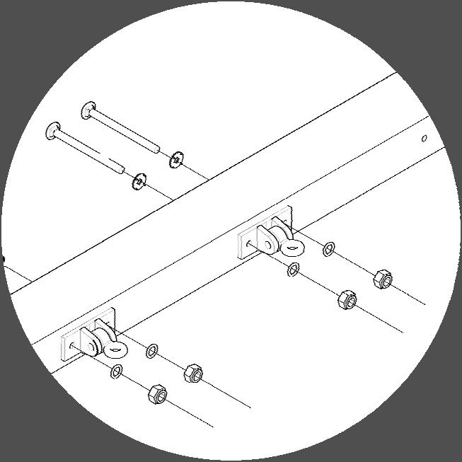
6 Prior to construction: Follow each assembly instruction in this booklet very carefully and thoroughly. Open all packages and parts bags and lay all parts that look the same together. Before using play center, review all maintenance and safety play tips and inspect for proper and complete assembly. Wear safety glasses at all times during assembly. Configuration shown may be altered according to layout desired and area placed Note: Bolts were designed to be very snug when inserted into pre-drilled holes. Use of a hammer will be necessary. NOTE : ALL BOLTS GET A WASHER, LOCK WASHER, AND A NUT IN THIS ORDER.

7
8 NOTE: Place all bolts so they have the nut in the counter sink part of the board, so they will not stick out and harm anyone. #8 #26A Countersink Countersink up #34 Countersink Inward Parts needed for step 1 (4) Part # ¾ 4x4 (2) Part #26A 7 6 4x4 (2) Part # x6 1. Using 7 bolts, connect part #8 to 2 of part #34 s with counter sink on part #34 facing inward. Counter sink on part #8 should be facing up. 2. Using 7 bolts, connect part #26A to 2 parts #34 s. Note: Locate counter sinks on part #26A they should be facing DOWN. 3. Tighten all connec ons and repeat for opposite side.
9 #28 Parts needed for step 2 (1) Part #28 6' 5" 4x4 1. Connect part #28 as shown with 7" bolts.
10 #80 Parts needed for step 3 (1) Part #80 8'5" 4x4 1. Connect part #80 to other side as shown with 7" bolts.
11 80 28
12 #7 #28 #7 #80 Parts needed for step 4 (2) Part #7 5' 6" 2x6 1. Do not tighten bolts. 2. Stand up both tower frames made in earlier steps 2 and 3. Note: Part #8 (4x6) on both tower legs should be on the inside of the tower. 3. Using 5" bolts, connect part #7 to both towers.
13 #5 #4 #3 Parts needed for step 5 (1) Part #3 4'10" 2x6 (1) Part #4 2'2" 4x4 (1) Part #5 2'2" 4x4 1. Facing the 2x6 (part #7) using 5" and 3 1/2" bolts, connect part #4 to the right hand side and connect part #5 to the left hand side. 2. Using 3" screws connect part #3 to the side of tower with part # Using a level and square, square up swing set and tighten all bolts.
14 #8 These two bolts will be replaced by 11" bolts in a later step. Parts needed for step 6 (1) Part #8 4'10" 4x6 1. Using 7" bolts connect part #8 to the tower as shown. Note: The counter sink on part #8 should face out.
15 #8 #1 #50 Countersink Direc ons Note: Note:
16 #51 #7 #3 #51 Parts needd for step 8 (1) Part #3 4'10" 2x6 (1) Part #7 5'6" 2x6 (2) Part # /2" 2x6 1. Using 5" bolts connect part #7 to main tower then stand up end frame and connect to other end of part #7. 2. Using 5" bolts attach parts #51 to tower legs as shown. 3. Using 3" screws attach part #3 as shown.
17 #4 #5 Part needed in step 9 (1) Part #4 2'2" 4x4 (2) Part #5 2'2" 4x4 1. Facing the 2x6 (part #7) connect part #4 to the right hand side using 5" and 3 1/2" bolts connect #5 to the left hand slide. 2. Connect rockwall to tower, using 11" bolts. The existing lower 7" bolts placed in the #8 will be removed and replaced with the 11" bolts. 3. To attach rocks, place rocks in random pattern by using the 1-1/2" screw in the small hole of the rock to place the rock. 4. After you have connected the rocks to the rock wall with the little screw, rotate the rock where you want it. Use the 2" screw and washer in the large hole of the rock to set the rock in place.
18 #9 Deck panels #9 Parts needed for step 10 (2) Part #9 4'11" 2x6 1. Place deck boards on top of 4x6 (part #8) and place #9's on the outside. 2. Using 3"screws; screw each 2x6 deck board into the 4x6 below. Use 2 screws on each end of deck board.
19 #9 Deck panels #9 Part needed for step 11 (2) Part #9 4'11" 2x6 1. Attach decking in same manner as step 10 using 3" screws.
20 Part needed for step Attach small ladder as shown using 3" screws.
21 #25 #25 #25 #25 Part needed in step 13 (4) Part #25 6'3" 4x4 1. Connect 2 part #25 to part #34 on upper tower using 7" bolts. 2. Connect 2 part #25 to parts #1 and #34 on lower tower using 7" bolts.
22 #6 #6 Parts needed for step 14 (2) Part #6 2'10 1/2" 4x4 Note: Refer to the next page for proper placement of part #6. 1. Attach #6 using 7" bolt on top. Screw up through the deck panel using 3" screws on bottom.
23 Opeining for small rail, slide, drawbridge or monkey bars 24" #25 #6 Opening for large rail or ladder 32" #25 #6 Opeining for small rail, slide, drawbridge or monkey bars 24" Step Each part #25 has two drilled holes near the center of the board. Using the correct hole placement, (depending upon your accessory options) bolt the #6 to the #25.
24 #50 #52 Parts needed for step 16 (1) Part #52 3'8 1/2" 4x4 1. Attach #52 using 7" bolts. The swing beam will attach to part #52. Note: Countersinks on part #52 will face away from the hole on the top of part #50 where it is attached.
25 Parts needed for step Attach ladder as shown using 7" bolts.

26 #14 #14 #14 Parts needed for step 18 (5) Part #14 1'11 3/4" 2x4 1. Attach part #14's using 3" screws. Handrails will set on the part #14's, so place them flush with the deck boards.
27 small rail small rails Parts needed for step Attach handrails to lower tower as shown using 3" screws.

28 Large rail Small rail "C" handrails Parts needed for step Attach handrails to upper tower using 3" screws. 2. Place small rail in opeing between 5' and 7' decks.
29 Small rails Parts needed for step Attach small handrail as shown using 3" screws.
30 Countersinks UP #1 #7 Countersinks DOWN #25 Parts needed for step 22 (2) Part #1 7'11 3/4" 4x4 (1) Part #7 5'6" 2x6 (1) Part #25 6'3" 4x4 1. Using 7" bolts a ach part #25 to 2 part #1's. Note: Counter sinks on parts #1 should be facing up. 2. A ach part # 7 to parts #1 using 5" bolts.
31 #70 11" bolts go here Parts needed for step 23 (2) Part # /2" 4x6 1. Attach 2 part #70 with 2 part #1 as shown using 7" bolts. Note: The counter sinks on part #70 should face in towards each other. 2. Stand up frame as shown and attach parts #70 to the 2 part #34's using 7" bolts on the outside and 11" bolts on the inside.
 using 5\" and 3 1/2\" bolts, attach part #4 to the right hand side and attach part")
32 #4 #5 Parts needed for step 24 (1) Part #4 2'2" 4x4 (1) Part #5 2'2" 4x4 1. Facing the 2x6 (part #7) using 5" and 3 1/2" bolts, attach part #4 to the right hand side and attach part #5 to the left hand side as shown.
33 Deck panels #9 Parts needed for step 25 (1) Part #9 4'11" 2x6 1. Using 3" screws attach both deck sections and part #9.
34 #7 Parts needed for step 26 (1) Part #7 5'6" 2x6 1. Attach part #7 as shown using 3" screws.
35 Parts needed for step Attach 3 rung ladder as shown using 3" screws.

36 #81 #81 #6 Parts needed for step 28 (1) Part #6 2'10 1/2" 4x4 (2) Part #81 2'7 7/8" 2x4 1. Attach #6 using 7" bolt on top. Screw up through the deck panel using 3" screws on bottom. 2. Attach part #81's using 3" screws. Note: Rails will sit on the #81's, so they need to be mounted flush with the deck panels.

37 Large Small rail Large rail Parts needed for step Attach rails as shown using 3" screws.
38 #23 #24 #22 Parts needed for step 30 (2) Part 24 9'5" 4x4 (1) Part /8" 4x6 (1) Part 22 8' 8 7/8" 4x4 1. Using 7" bolts connect both part #24's to part #23 as shown. Note: Countersink on part #23 must be on the bottom. 2. Using 7" bolts connect part #22 to both part #24's.
39 Step Attach swing beam as shown using 11" bolt.

40
41 9" bolt #52 #27 #50 Step Attach end of swing beam to parts #50 and #52 using 9" and 7" bolts. 2. Attach part #27 on top of parts #80 and #28 using 4" lag screw. Hint: Start lags with a hammer, do not over tighten.

42 Slide openings Step Lay slide in openings and attach with 1/4" x 1" Fender Washers on 3 slide screws (1 1/2" Phillips head screws.) Place screws through top of slide and screw tightly into decking.
43 Flush 30-1/2 3 Screws Two at each location. Flush #95 Center Tube Slide Face Plate in opening. # /2 #97 #95 #96 #97
44 NOTE:

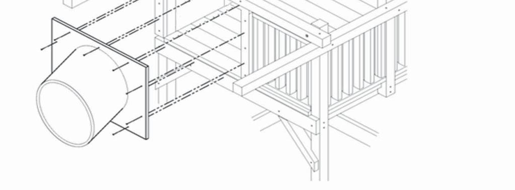
45 SWING INSTALL minimum

46 Attaching rocks to rock wall 1. Place rocks to rock wall in random pattern and mark hole positions. Pre drill marked holes using 5/16" drill bit. Pound T Nut in back of rock wall. 2. Install Rock using 1/4 x 2" Hex bolt, lock washer, and flat washer. Slide installation Place slide on deck 3" from the edge and secure using three 1 1/2" slide screws and Fender washers through the top of the slide and screw tightly into the decking. 3"
47 #102 26A #102 Parts needed for step 1 (4) Part #102 2x4 5' 1 1/8" 1. Attach part #102 as shown using 3" screws.
48 #27A Parts needed for step 2 (1) Part #27A 2x4 5' 6" 1. Attach part #27 to the top of #28 using 4" x 3/8" lag bolt.
49 #104 #104 Parts needed for step 3 (2) Part #104 2x4 39 1/2" 1. Attach part #104 using 3" screws.
50 #101 Parts needed for step 4 (22) Part #101 2x6 6' 2" 1. Attach part #101, starting at top of the roof using 3" screws. Work downward centering boards, so the overhang is about 4" on both sides of the #102. HINT: Temporarily screw a part #101 at the bottom for the other #101's to rest on while you attach screws.
51
52 2 SECTIONS WITH OVER- LAPPING FLANGES 3 SECTIONS WITHOUT OVERLAPPING FLANGES 3-1/2 LAG SCREW W/WASHER 5/16 X 1 BOLT W/WASHERS AND LOCK NUT 5/16 X 3/4 BOLT W/WASHER *** THIS PRODUCT IS INTENDED FOR RESIDENTIAL USE ONLY.***
53 STEP 1: ATTACHING ENTRANCE TUBE TO THE CORNER POSTS Take the FACE PLATE ENTRY piece labeled #1 and place it flush to the corner posts, so that the bottom of the large circular opening is flush to the TOP of the deck boards. Fasten the FACE PLATE ENTRY to the corner posts with 3-1/2 lag screws and 3/8 washers in all the holes. **NOTE: YOU MAY HAVE TO DRIVE THE LAG SCREWS IN AT AN ANGLE TO CONTACT THE CORNER POSTS PROPERLY.** NOTE: DO NOT TIGHTEN UNTIL ALL BOLTS, NUTS, AND WASHERS ARE IN PLACE. **YOU MAY HAVE TO DRIVE THE LAG SCREWS IN AT AN ANGLE TO CONTACT THE COR- NER POSTS PROPERLY.** FACE PLATE ENTRY Bottom of large circular opening in the FACE PLATE ENTRY is flush to the TOP of the deck.
54 STEP 2: ASSEMBLING THE FIRST CURVED SECTION Locate a top SLIDE SECTION (Labeled #2) with an overlapping flange and a bottom SLIDE SECTION (Labeled #3) without an overlapping flange. Fasten the top and bottom SLIDE SECTIONS together along the flanges (ribs) with 5/16 x 1 hex bolts and 5/16 lock nuts. Use a washer on both sides of the flange (rib). Make sure to place a nut/bolt with washers in each hole provided on the inside and outside ribs of the SLIDE SECTIONS. NOTE: DO NOT TIGHTEN UNTIL ALL BOLTS, NUTS, AND WASHERS ARE IN PLACE.

55 STEP 3: ATTACHING FIRST CURVED SECTION TO FACE PLATE ENTRY SECTION Now that the first CURVED SECTION is assembled, raise it up to the FACE PLATE ENTRY SECTION with the RIB vertical and the CURVED SECTION facing down. The RIB in the CURVED SECTION will get rotated TWO holes to the RIGHT. Align the holes in each of the flanges of the FACE PLATE ENTRY SECTION and the first CURVED SECTION. Fasten the sections together with 5/16 x 1 hex bolts, 5/16 washers and 5/16 Lock Nuts. Use a washer on both sides of the flange. Fasten the sections together at the TOP and BOT- TOM first, then fasten the rest of the nuts/bolts. NOTE: DO NOT TIGHTEN THE FASTENERS UNTIL ALL BOLTS, NUTS AND WASHERS ARE IN PLACE. FACE PLATE ENTRY SECTION Mid-Line Rotate RIGHT TWO holes. RIB TWO holes between mid-line and RIB. first CURVED SECTION
56 STEP 4: ASSEMBLING THE SECOND CURVED SECTION Locate a top SLIDE SECTION (Labeled #2) with an overlapping flange and a bottom SLIDE SECTION (Labeled #3) without an overlapping flange. Fasten the top and bottom SLIDE SECTIONS together along the flanges (ribs) with 5/16 x 1 hex bolts and 5/16 lock nuts. Use a washer on both sides of the flange (rib). Make sure to place a nut/bolt with washers in each hole provided on the inside and outside ribs of the SLIDE SECTIONS. NOTE: DO NOT TIGHTEN UNTIL ALL BOLTS, NUTS, AND WASHERS ARE IN PLACE. NOTE: DO NOT TIGHTEN UNTIL ALL BOLTS, NUTS, AND WASHERS ARE IN PLACE.

57 STEP 5: ATTACHING SECOND CURVED SECTION TO FIRST CURVED SECTION Now that the second CURVED SECTION is assembled, raise it up to the first CURVED SECTION aligning the RIBS in the sections. The CURVED SECTIONS should make a U shape at this point. Rotate the RIB in the second CURVED SECTION two holes to the LEFT. Fasten the second CURVED SECTION to the first CURVED SECTION with 5/16 x 1 hex bolts, 5/16 washers and 5/16 lock nuts. Use a washer on both sides of the flange. Fasten the sections together at the TOP and BOTTOM first, then fasten the rest of the nuts/bolts. NOTE: DO NOT TIGHTEN THE FASTENERS UNTIL ALL BOLTS, NUTS AND WASHERS ARE IN PLACE. first CURVED SECTION RIB TWO holes between ribs. second CURVED SECTION

58 STEP 6: EXIT SECTION ASSEMBLY Locate the top EXIT PIECE (Labeled #4 with large cutout section) and the bottom exit piece (Labeled #5 this is the only curved section remaining). Fasten the exit pieces along the ribs with 5/16 x 1 long bolts and nuts provided using a washer on both sides of the flange. Make sure to fasten the nuts and bolts in each hole provided on the ribs, on both sides of the top and bottom exit pieces. NOTE: DO NOT TIGHTEN THE FASTENERS UNTIL ALL BOLTS, NUTS AND WASHERS ARE IN PLACE. EXIT PIECE (with cut out section) Bottom exit piece (This is the last curved slide section left.)
59 STEP 7: ATTACH FOOT STAND TO EXIT SECTION Locate the FOOT STAND PIECE. Rotate the FOOT STAND PIECE so that the there is one hole showing on the LEFT on the EXIT SECTION. Fasten the FOOT STAND PIECE to the EXIT SECTION with 5/16 x 3/4 long bolts and washers. Make sure to fasten all 6 bolts in each of the holes provided in the FOOT STAND PIECE. EXIT SECTION ONE hole should be showing here. FOOT STAND PIECE
60 STEP 8: ATTACHING THE SECOND CURVED SECTION TO THE EXIT SECTION Now that the EXIT SECTION and FOOT STAND PIECE are assembled, raise the EXIT SECTION up to the second CURVED SECTION and align the holes in the flanges of the second CURVED SECTION and the EXIT SECTION so that the foot rests squarely on the ground. Fasten the EXIT SECTION to the second CURVED SECTION with 5/16 x 1 hex bolts and 5/16 lock nuts using a 5/16 washer on each side of the flange. Fasten the sections together at the TOP and BOTTOM first, then fasten the rest of the nuts/bolts. NOTE: DO NOT TIGHTEN THE FASTENERS UNTIL ALL BOLTS, NUTS AND WASHERS ARE IN PLACE. NOTE: OTHER SECTIONS NOT SHOWN FOR CLARITY. TWO holes between ribs. second CURVED SECTION EXIT SECTION
61 THIS IS THE COMPLETED SUPER TUBE ASSEMBLY
62 LIMITED THREE YEAR WARRANTY 1. Subject to proper installation, Kid s Creations, L.L.C. warrants, subject to the limitations stated below, to the original retail purchaser that all Kid s Creations, L.L.C. playground equipment and structures and each component part will be free from defects in workmanship and materials for a period of three (3) years. In addition, Kid s Creations, L.L.C., warrants all ropes and canvas for a period of one (1) year. 2. Additionally, Kid s Creations, L.L.C. warrants to the original purchaser that all redwood components will be free from deterioration which impairs the structural integrity of the unit for the life time of the original purchaser. Wooden components in your Kid s Creations, L.L.C. system will have imperfections, seasonal and surface cracks, knot holes and knots. Natural characteristics of all wooden play equipment, not resulting in structural failure, are not covered under this warranty. 3. Kid s Creations, L.L.C. reserves the right to examine photographs or physical evidence of equipment claimed to be defective, and to recover said equipment, prior to disposition of warranty claims. Equipment returned to our factory for examination or recovery must be shipped freight prepaid, unless a Return Authorization Number is issued. 4. No warranty is offered on equipment subjected to abuse, negligence, improper installation, vandalism, acts of God, unauthorized alteration or attachment to equipment other than our own, or improper use, service or repair by customer or any third party. Please supervise your children s play activity and maintain your play equipment periodically. 5. This warranty is limited to equipment used for residential, single-family dwellings and specifically excludes commercial or institutional use. 6. The term of the warranty begins on the date the equipment is delivered to the purchaser or such destination as the purchaser shall designate. 7. In the event of a defect covered by this warranty, Kid s Creations, L.L.C. will remedy the defect, without charge, to the purchaser within a reasonable time. The remedy will consist of repair or replacement of the equipment, or refund of the purchase price, at the option of Kid s Creations, L.L.C. 8. KID S CREATIONS, L.L.C. DISCLAIMS ALL OTHER REPRESENTATIONS AND WARRANTIES OF ANY KIND, EXPRESS OR IMPLIED, IN FACT OR IN LAW, INCLUDING, WITHOUT LIMITATION, THE IMPLIED WARRANTY OF MERCHANTABILITY OR THE IMPLIED WARRANTY OF FITNESS FOR A PARTICULAR PURPOSE. 9. KID S CREATIONS, L.L.C. SHALL NOT BE LIABLE FOR ANY INCIDENTIAL OR CONSEQUENTIAL DAMAGES FOR FAILURE TO PERFORM ITS OBLIGATIONS UNDER THIS AGREEMENT. ADDITIONALLY, INCIDENTAL AND CONSEQUENTIAL DAMAGES SHALL NOT BE RECOVERABLE EVEN IF THE REPAIR, REPLACEMENT, OR REFUND REMEDY FAILS OF ITS ESSENTIAL PURPUSE OR FOR ANY OTHER REASON. NOTWITHSTANDING ANY LANGUAGE TO THE CONTRARY SET OUT IN THIS WARRANTY, NOTHING IN THIS WARRANTY SHALL BE CONSTRUED TO LIMIT OR DISCLAIM ANY WARRANTY, WHETHER STATUTORY OR IMPLIED AT COMMON LAW, WHICH UNDER APPLICABLE STATE LAW, CANNOT BE LAWFULLY LIMITED OR DISCLAIMED. 10. To obtain performance of any obligation under this warranty or to inquire about warranty performance, the purchaser must contact Kid s Creations, L.L.C., 800 N. Maple, Garnett, Kansas 66032, or call This warranty gives you specific legal rights, and you may also have other rights that vary from state to state.
Important safety considerations
 Important safety considerations This product is intended for use by children not less than 2 years of age. Warning: possible problems of entrapment could occur if used by children under 2 years of age.
Super Tube Spiral Slide Instructions
 Super Tube Spiral Slide Instructions Super Tube Spiral Slide 2 SECTIONS WITH OVERLAPPING FLANGES 3 SECTIONS WITHOUT OVERLAPPING FLANGES 3-1/2 LAG SCREW W/WASHER 5/16 X 1 BOLT W/WASHERS AND LOCK NUT 5/16
Classic Tire Swing Set
 Owners & Instruction Manual Classic Tire Swing Set This instruction booklet is to be used exclusively for Eastern Jungle Gym customers only. It is not to be handed out to the general public. Any duplication
PB 8328 WS 8328 IMPORTANT!! JAMBOREE
 PB 8328 WS 8328 JAMBOREE IMPORTANT!! PLEASE READ BEFORE BEGINNING ASSEMBLY!! Please make sure all lumber, hardware and accessory parts are accounted for. If you are missing anything, please DO NOT RETURN
Owner s Manual & Safety Instructions
 Owner s Manual & Safety Instructions Save This Manual Keep this manual for the safety warnings and precautions, assembly, operating, inspection, maintenance and cleaning procedures. Write the product s
Spa & Hot Tub Necessities. Cover Removal System Installation & Use Manual
 Spa & Hot Tub Necessities Cover Removal System Installation & Use Manual SET-UP AND ASSEMBLY BEFORE BEGINNING ASSEMBLY, CAREFULLY READ THE FOLLOWING INFORMATION AND INSTRUCTIONS: Place all parts in a cleared
Lodge II Pergola. Manual and Installation Instructions. Please read these instructions before removing parts from crate
 Lodge II Pergola Manual and Installation Instructions Please read these instructions before removing parts from crate Introduction Thank you for your purchase from The Outdoor GreatRoom Company. This pergola
Installation Manual Roof Zone Ladder Rack
 Installation Manual Roof Zone Ladder Rack 102113,E1346 Installation Time: About 90 minutes. Depending on truck and Do-it-Yourself experience level Tools Required: Electric Drill with 1/2 Chuck 1/2 & 7/32
Assembly Instructions and Parts Manual JPSF-1 Fence and JPSR Rail Set
 Assembly Instructions and Parts Manual JPSF-1 Fence and JPSR Rail Set WALTER MEIER (Manufacturing) Inc. 427 New Sanford Road LaVergne, Tennessee 37086 Part No. M-708482 Ph.: 800-274-6848 Revision C2 02/2013
Sunset Swings By Health in Motion, LLC
 Sunset Swings By Health in Motion, LLC Model 421 Lounge Swing Assembly and Operation Manual Record Serial Number Here www.sunsetswings.com by Health In Motion, LLC. 11/6/2009 421 Owners Assembly and Operation
1531 Fort Add On **!!IMPORTANT-PLEASE READ!!**
 1531 Fort Add On **!!IMPORTANT-PLEASE READ!!** This Add-On kit will require you to deviate from the main instruction manual. Please follow the outline below so that you will know what steps to be aware
UNIVERSAL STAND. Owner s Manual. Visit us on the web at QUESTION Model No. UT1002
 Owner s Manual Model No. UT1002 UNIVERSAL STAND QUESTION... 1 877 393 7121 Visit us on the web at www.southerntechllc.com You will need this manual for safety instructions, operating procedures, and warranty.
SawStop. Contractor Fence Assembly OWNER S MANUAL. Model CNS-SFA
 Contractor Fence Assembly OWNER S MANUAL Model CNS-SFA Warranty warrants to the original retail purchaser of the Contractor Fence Assembly accompanying this manual that the fence assembly will be free
Backyard Play Systems. Playset. Recommended for Ages 3 to 11 - BEFORE YOU BEGIN - - NOTICE -
 2690-MB 1/25/2013 Customer Service 1-866-890-2211 1000 Ternes Drive Monroe, MI 48162 Backyard Play Systems Playset Model 4097 Model 6314 Tools Required Socket Set Hammer 9/16" Combination Wrench 3/16"
Creating Childhood Memories Owners & Instruction Manual
 R Creating Childhood Memories Owners & Instruction Manual Dream This instruction booklet is to be used exclusively for Eastern Jungle Gym customers only. It is not to be handed out to the general public.
Owner s Manual AE PLUG AERATOR MANUFACTURING QUALITY LAWN CARE EQUIPMENT SINCE Made In CHINA REV
 MANUFACTURING QUALITY LAWN CARE EQUIPMENT SINCE 1945 Owner s Manual AE-48 48 PLUG AERATOR IMPORTANT Read and follow all Safety Precautions and Instructions Before Operating this Equipment. Made In CHINA
Real Life Ninja Complete Starter Pack (14ft. Warped Wall) Assembly Instructions
 Assembly Instructions") MATERIALS: 3 - Main Sections (Only 2 Sections for 10 ) 8 3 deck screws for joining sections inside of 2 Rock Wall Panels (with pre-installed t-nuts. Top panel comes with ladder mounting block preinstalled.)
MATERIALS: 3 - Main Sections (Only 2 Sections for 10 ) 8 3 deck screws for joining sections inside of 2 Rock Wall Panels (with pre-installed t-nuts. Top panel comes with ladder mounting block preinstalled.)
Planishing hammer stand For use with SKU Planishing hammer
 Planishing hammer stand For use with SKU 94847 Planishing hammer Model 96300 Assembly And Operation Instructions Please Note: Planishing Hammer not included with Stand. Due to continuing improvements,
DRIVEWAY SERIES D554 D560
 DRIVEWAY SERIES D554 D560 Version ' Keep this instruction manual in case you have to contact the manufacturer for replacement parts. 2 FAILURE TO FOLLOW THESE WARNINGS MAY RESULT IN SERIOUS INJURY AND/OR
OPERATORS MANUAL WEEKENDER STEEL LADDER RACK
 OPERATORS MANUAL WEEKENDER STEEL LADDER RACK WWW.WEATHERGUARD.COM MODELS 1450 & 1475 1475 Shown INSTALLATION TIME Approximate installation time: 60 minutes (depending on truck equipment installation experience
Loading Dock Safety Gate
 Installation Instructions/Operation and Maintenance Manual Models LDSG-120-PCY LDSG-144-PCY Table of Contents Product Information...2 Parts List...3 Installation Instructions...5 Operation...13 Inspection
Assembly Instructions and Parts Manual JPSF-1 Fence and JPSR Rail Set #
 Assembly Instructions and Parts Manual JPSF-1 Fence and JPSR Rail Set #1002493 JET 427 New Sanford Road LaVergne, Tennessee 37086 Part No. M-708482 Ph.: 800-274-6848 Revision C3 02/2014 www.jettools.com
ASPEN OUTDOOR TABLE TENNIS
 ASPEN OUTDOOR TABLE TENNIS Replacement Parts Order direct at or call our Customer Service department at (800) 225-7593 8 am to :30 pm Central Standard Time January 201 UPC Code 7-19265-51830-3 Staple your
Owner s Manual & Safety Instructions
 Owner s Manual & Safety Instructions Save This Manual Keep this manual for the safety warnings and precautions, assembly, operating, inspection, maintenance and cleaning procedures. Write the product s
Models 2230 and 2240
 Models 2230 and 2240 Overview... 2 Tools Needed... 2 Hardware...3 Assembly... 4-13 Installation... 14 Drawer Removal... 15 Operation... 15 Maintenance... 15 Accessories... 16 Limited Warranty... 16 Perform
STOP! Call Us First! DO NOT RETURN TO STORE.
 2293-SB - NOTICE - This playset product is not intended for public use. It is intended for residential application and is not warranted for public or commercial use. STOP! Call Us First! DO NOT RETURN
Sonoma Outdoor Kitchen Pergola. Assembly Instructions
 Sonoma Outdoor Kitchen Pergola Assembly Instructions Introduction Thank you for your purchase from The Outdoor GreatRoom Company. This pergola has been engineered and manufactured in the USA. This user
SawStop. T-GlideTM. Fence System- Professional Series II OWNER S MANUAL
 SawStop T-GlideTM Fence System- Professional Series II OWNER S MANUAL Warranty SawStop warrants to the original retail purchaser of a new T-Glide Fence System - Professional Series II from an authorized
Manual Carton Closing Staplers
 Operator s Manual Manual Carton Closing Staplers SHB00-A Item No. 6400 -/8" Crown Carton Closing Stapler 5/8" and /4" (5mm and 8mm) Ask for Genuine INTERCHANGE A58 and A4 Staples SHB50-C Item No. 640 -/4"
15 Planer Stand. Model Due to continuing improvements, actual product may differ slightly from the product described herein.
 15 Planer Stand Model 96316 Assembly And Operation Instructions Due to continuing improvements, actual product may differ slightly from the product described herein. 3491 Mission Oaks Blvd., Camarillo,
Powered by. For further installation assistance: prxperformance.com/pages/murphy-rack
 Powered by The 90 Fold-in Murphy Rack is made by the creators of the original Profile Folding Rack at PRx Performance and is Patent Pending. An up-to-date record of patents and patent pending items can
Install Instructions. NewAge Steel Welded Tall Locker
 Kit Contains Full Width Adjustable Steel Shelves (4) Height-Adjustable Steel Leveling Legs (4) Aluminum Door Trim (2) 2.5 x ¼ Cabinet Mounting Lag Bolts (4) Large Zinc Plated Mounting Washers (4) 5/8 x
Page 1 of 18. SunRail System Installation Instructions
 Page 1 of 18 SunRail System Installation Instructions Page 2 of 18 SunRail Stainless Steel Railing Installation Guide Table of Contents Before You Begin 3 Installing Surface Mount Bases for a Two Rail
MONKEY TOWER PG123W. RECOMMENDED TOOLS: Impact Driver (2) Saw Horses (4) Bar Clamps or C-Clamps
 Saw Horses (4) Bar Clamps or C-Clamps") MONKEY TOWER PG3W REQUIRED TOOLS: () 3/4" Sockets and Ratchets 3/4" Wrench /" Socket and Wrench 9/6" Socket and Wrench 5/6" Allen Wrench Drill with Phillips Driver Bit 3/8" Drill Bit /8" Drill Bit Hammer
MONKEY TOWER PG3W REQUIRED TOOLS: () 3/4" Sockets and Ratchets 3/4" Wrench /" Socket and Wrench 9/6" Socket and Wrench 5/6" Allen Wrench Drill with Phillips Driver Bit 3/8" Drill Bit /8" Drill Bit Hammer
LM600 Landmark Permanent Blind
 LM600 Landmark Permanent Blind Get parts online at www.huntriversedge.com P/N: 23033 REV1: 02/23/16 2016 RETI All Rights Reserved INTRODUCTION Landmark Permanent Blinds are engineered with you the hunter
Please Do Not Return This Product To The Store!
 MODEL NO. T8176 QUICK SERVE 3000 TABLE TENNIS TABLE OWNER'S MANUAL 1. Read this manual carefully before starting assembly. Read each step completely before beginning each step. 2. Some smaller parts may
Models 2130 and 2140
 Models 2130 and 2140 Overview... 2 Tools Needed... 2 Hardware... 2 Assembly... 3-10 Installation...11 Operation... 11 Maintenance... 12 Accessories...12 Limited Warranty... 12 Perform the following sequence
INSTALL INSTRUCTIONS WELCOME TO THE NEWAGE PERFORMANCE CABINETRY SERIES NEWAGE STEEL WELDED CABINETRY
 NEWAGE STEEL WELDED CABINETRY WELCOME TO THE NEWAGE PERFORMANCE CABINETRY SERIES ALL CABINETS MUST BE MOUNTED TO STUDS ON A SECURE WALL, AS PER THESE INSTRUCTIONS. FAILURE TO DO SO MAY RESULT IN SERIOUS
Models 2130 and 2140
 Models 2130 and 2140 Overview... 2 Tools Needed... 2 Hardware... 2 Assembly... 3-10 Installation...11 Operation... 11 Maintenance... 12 Accessories...12 Limited Warranty... 12 Printed in USA 2007 Perform
Owner s Manual LSP38 38 Lawn Sweeper
 Owner s Manual LSP38 38 Lawn Sweeper Manual Contents Safety Instructions Assembly Operation Maintenance Parts Warranty 2 4-13 2 11 14-15 16 Your Lawn Sweeper Congratulations on your purchase of a new Precision
INSTALLATION INSTRUCTIONS
 INSTALLATION INSTRUCTIONS Premier Mounts Tilting Wall Mount Model: TWM-085 For use with Panasonic 85 Flat Panel NORTH AMERICA 3130 East Miraloma Avenue Anaheim, CA 92806 USA USA and Canada Phone: 1.800.368.9700
OWNER S MANUAL with Assembly Instructions
 OWNER S MANUAL with Assembly Instructions VISIT E LIFETIME WEB SITE: WWW.LIFETIME.COM ** Do Not Contact the Store ** For Assistance, including missing or broken parts, Call Customer Service at: 1 (800)
GearBoss II High Density storage
 Assembly/Owner s Manual GearBoss II High Density storage contents Safety...........................................2 General......................................2 Installation...................................2
READ CAREFULLY - FAILURE TO FOLLOW INSTRUCTIONS AND SAFETY RULES MAY RESULT IN SERIOUS INJURY
 LSV30108C LS5002C cradle bundle 108 LS5004B bunk bundle LSV40108C LS5002C cradle bundle 108 LS5004B bunk bundle LS5007B diagonal bundle LSV30120C LS5012C cradle bundle 120 LS5004B bunk bundle LSV40120C
Installation Instructions Tailgate Rack Bracket
 Installation Instructions Tailgate Rack Application: Jeep Wrangler 1986 Current Part Number: 41411 www.bestop.com - We re here to help! Visit our web site and click on Ask a Question. Click here for more
ASSEMBLY INSTRUCTIONS FOR HAULER II UNIVERSAL CAMPER SERIES RACKS
 ASSEMBLY INSTRUCTIONS FOR HAULER II UNIVERSAL CAMPER SERIES RACKS C11U2873-1 shown above Package Contents: HARDWARE KIT PARTS (4) 3/8-16 x 3 CARRAIGE BOLTS (1) RAIL DRIVER S SIDE ASSEMBLY (20) 3/8-16 x
ASSEMBLY INSTRUCTIONS FOR HAULER II SERVICE BODY A RACK
 ASSEMBLY INSTRUCTIONS FOR HAULER II SERVICE BODY A RACK T12USBA-1 shown above Package Contents: HARDWARE KIT PARTS (4) 3/8-16 x 3 CARRAIGE BOLTS (1) RAIL DRIVER S SIDE ASSEMBLY (20) 3/8-16 x 2 CARRAIGE
Installation Instructions BestRail Ladder Rack Must be used with BestRail Accessories: Overhead Rack
 Installation Instructions BestRail Ladder Rack Must be used with Accessories: 42791 Can be used with Accessories: 42793 Tie Down 42794 Retractable Tie Down The channels in the Ladder Rack are the same
Models 2030 and 2040
 Models 2030 and 2040 Overview... 2 Tools Needed... 2 Hardware... 2 Assembly... 3-8 Installation... 9 Operation... 9 Maintenance... 10 Accessories... 10 Limited Warranty... 10 Document # 101290 0607 Printed
Installation Instructions Hinged Roof Rack
 Installation Instructions Hinged Roof Rack Application: Jeep Wrangler Unlimited 2004 - Current Part Number: 41435-01 www.bestop.com - We re here to help! Visit our web site and click on Ask a Question
Installation Instructions/Operation and Maintenance Manual. PS DOORS Contact Information. Website psdoors.com
 Ladder Safety Gate Installation Instructions/Operation and Maintenance Manual Models All Models: LSG-5 to LSG-48 Table of Contents Product Information...2 Inspection & Mainteance...2 Warranty Information...2
LSP inc. READ CAREFULLY - FAILURE TO FOLLOW INSTRUCTIONS AND SAFETY RULES MAY RESULT IN SERIOUS INJURY
 LSP inc. Canopy Frame Owner s Manual 14AF64 14' Canopy Frame LS311 bent tube bundle 14' LS321 rail bundle 14' LS310 leg bundle 16AF64 16' Canopy Frame LS311 bent tube bundle 14' LS321 rail bundle 14' LS310
Owner s Manual and Assembly Instruction
 Owner s Manual and Assembly Instruction Model #: 22-PS120 Model Name: Verona III Swing Set Manual Date: September, 2007 Important: Keep this owner s manual; do not discard in case you need to contact Pacific
OWNER S MANUAL Table Tennis Table Patent Pending
 OWNER S MANUAL Table Tennis Table Patent Pending Be sure to write your model number and serial number here for future reference. You can find these numbers printed on the bottom of the table. MODEL # T8266
MERRY GO ROUND ITEM NO: 8030
 MERRY GO ROUND ITEM NO: 8030 OWNER S MANUAL CAUTION: This unit is designed to be used safely by up to 4 children between the ages of 3 years to 8 years old with a maximum weight of 00 pounds (45.4 kgs)
M ACS Instructions
 APPLICABLE MODELS: Nissan Frontier 2005 and up short bed with Utili-Trak mounting rails PACKAGE CONTENTS 00-0060-M-01-1205 ACS Instructions Leitner Designs 25675 Taladro Circle Unit E Mission Viejo, CA
Installation Instructions Cage Kit JK Unlimited (4-Dr) Part # 76902
 Part # 76902") Please read instructions entirely before installing this product. Drilling is required to install this part. Parts Included Qty Parts Included Qty Driver Front Upright 1 Pass Side Drill Template (7289)
Please read instructions entirely before installing this product. Drilling is required to install this part. Parts Included Qty Parts Included Qty Driver Front Upright 1 Pass Side Drill Template (7289)
Hardware Box 1 1/4 Diameter x 3/4 Long Bolts 24 1/4 Nylon Lock Nut 24 1/4 Diameter x 3 Long Lag Bolt 8 1/4 Washers 56
 Warning: Excessive weight hazard! Use two or more people to move, assemble or install overhead rack to avoid back or other injury. Do not leave children unattended near overhead rack. High risk of injury
ATTENTION! IMPORTANT! This manual supersedes Manual 2692 in the Base Kit.
 2999 ATTENTION! IMPORTANT! This manual supersedes Manual 2692 in the Base Kit. (This page intentionally left blank.) 2999 - NOTICE - This playset product is not intended for public use. It is intended
FXL-168 FIXED RACK ASSEMBLY INSTRUCTIONS SALES ORDER #
 ZOMEWORKS FXL-168 FIXED RACK ASSEMBLY INSTRUCTIONS SALES ORDER # 1 1011 Sawmill Road NW, PO Box 25805, Albuquerque, NM 87125 USA (505) 242-5354 / (800) 279-6342 / FAX (505) 243-5187 E-mail: zomework@zomeworks.com
ATTENTION! IMPORTANT! If you have the Fort and Terrace options this manual supersedes Manual 2692 in the Base Kit.
 2998 ATTENTION! IMPORTANT! If you have the Fort and Terrace options this manual supersedes Manual 2692 in the Base Kit. (This page intentionally left blank.) 2998 - NOTICE - This playset product is not
Extreme Tube Slide - 5ft.
 Extreme Tube Slide - 5ft. Part Number: 03-0014 Revison: A 6.12.2013 Please inspect and inventory all parts immediately upon accepting delivery. Use the inventory pages in the manual to make sure you have
Owner s Manual ODYSSEY BENCH MODEL. O4100B shown REV E. Southern Avenue, Phoenix, AZ USA Workhorseproducts.
 Owner s Manual ODYSSEY BENCH MODEL O4100B shown 67-1375 REV 218 3730 E. Southern Avenue, Phoenix, AZ 85040 USA 800-778-8779 Workhorseproducts.com 1 Table of Contents I. Introduction & Safety Information.
F 8:00 AM 6:00 PM EST 8:30 AM 4:30 PM EST
 2692 - NOTICE - This playset product is not intended for public use. It is intended for residential application and is not warranted for public or commercial use. STOP! Call Us First! DO NOT RETURN TO
Installation Instructions TrekStep Side Mount
 Installation Instructions TrekStep Side Mount Vehicle Application Chevrolet Silverado / GMC Sierra All Bed Sizes 1999 Current Part Number: 75400-15 www.bestop.com - We re here to help! Visit our web site
INCLUDES BENCH MODELS:
 SHOOTING BENCH OWNERS MANUAL & USAGE INSTRUCTIONS INCLUDES BENCH MODELS: AR02-B The Deluxe Shooting Bench AR03-B The Swivel Action Shooting Bench AR02-B DELUXE SHOOTING BENCH WARNING: Do not use without
Sonoma 1216 Pergola Manual and Installation Instructions. Please read these instructions before removing parts from crate
 Sonoma 1216 Pergola Manual and Installation Instructions Please read these instructions before removing parts from crate Introduction Thank you for your purchase from The Outdoor Greatoom Company. This
PATRIOT DOCKS ASSEMBLY INSTRUCTIONS
 6/1/2008 PATRIOT DOCKS ASSEMBLY INSTRUCTIONS Congratulations on your new Patriot Dock purchase. This manual contains instructions to assemble basic dock configurations for use at typical shoreline application.
Shop Style Miter Saw Stand Kit
 Quality Power Tool Accessories OWNER S MANUAL Assembled Unit Shown Without Shelves & Wings Assembled With Shelves & Wings Shop Style Miter Saw Stand Kit Model 2850 IMPORTANT Read and understand all safety
Single-Sliding Header Mount INSTALLATION INSTRUCTIONS
 1-800-701-4782 Single-Sliding Header Mount INSTALLATION INSTRUCTIONS GATEWAY SO# OPENING SIZE: W x H PULLEY SYSTEM: YES / NO Upon receiving your Gateway Door, inspect packaging and contents for freight
Model 6360/6361. Ambulance Cot Fastener INSTALLATION/OPERATION INSTRUCTIONS. IMPORTANT Keep manual on file at all times.
 IMPORTANT Keep manual on file at all times. Model 6360/6361 Ambulance Cot Fastener INSTALLATION/OPERATION INSTRUCTIONS For Parts or Technical Assistance 1 800 784 4336 Table of Contents Introduction..............................................................................
ATTENTION: PLEASE READ AND UNDERSTAND ALL INSTRUCTIONS AND WARNINGS BEFORE ASSEMBLING, INSTALLING OR USING THIS PRODUCT.
 PLAN YOUR VAN (TIPS FOR FASTER INSTALLATION) Installing your Transit bulkhead is very clear cut following these instructions. Before cutting or drilling in the floor, verify the location of you gas tank,
Please Do Not Return This Product To The Store!
 MODEL NO. B330 Goalrilla E BASKETBALL SYSTEM OWNER'S MANUAL. Read this manual carefully before starting assembly. Read each step completely before beginning each step.. Some smaller parts may be shipped
Black or White Classic Country Chair Item Number Black Chair: BH Item Number White Chair: BH
 ASSEMBLY INSTRUCTIONS Black or White Classic Country Chair Item Number Black Chair: BH10-084-90-1 Item Number White Chair: BH10-084-90-14 CUSTOMER SERVICE INFORMATION If parts are missing, DO NOT return
00108/00110 INSTRUCTION MANUAL
 00108/00110 INSTRUCTION MANUAL Removable and Adjustable Mudflap System IMPORTANT! Please Read this Instruction Booklet prior to assembly of your Rock Tamer Kit. IMPORTANT! Exhaust Systems Note: Any modifications
Specifications. Important Safety Information
 Specifications Tire Rim Capacity 4 to 12 Rim Height 16 (2) Bead Breaker Handles 21 Long Includes Aluminum Centering Cone (2) Nylon Spacers Important Safety Information 1. Do not exceed max. tire capacity.
1300-lb Furniture and Crate Movers
 1300-lb Furniture and Crate Movers Owner s Manual WARNING: Read carefully and understand all ASSEMBLY AND OPERATION INSTRUCTIONS before operating. Failure to follow the safety rules and other basic safety
Please Do Not Return This Product To The Store!
 MODEL NOS. T81 TABLE TENNIS TABLE OWNER'S MANUAL 1. Read this manual carefully before starting assembly. Read each step completely before beginning each step.. Some smaller parts may be shipped inside
Swing Beam Kit PB 8263 ASSEMBLY INSTRUCTIONS
 PB 8263 Swing Beam Kit check out http://www.swing-n-slide.com/planupdates.html for updates to these instructions For more information, visit this link: http://www.swing-n-slide.com 28' Minimum Safe Use
P4263TP. Installation Guide. Low-Profile Tilting Portrait Mount for Flat-Panels
 Low-Profile Tilting Portrait Mount for Flat-Panels 1321 S. State College Blvd., Fullerton, CA 92831 USA Weight Limit Maximum Flat Panel Weight: 175 lbs. Warning Statements THE WALL STRUCTURE MUST BE CAPABLE
Owner s Manual LSV1364
 Owner s Manual LSV1364 1300 lb, 64" Beam Vertical Lift READ CAREFULLY - FAILURE TO FOLLOW INSTRUCTIONS AND SAFETY RULES MAY RESULT IN SERIOUS INJURY Manufacturers of Lakeshore Products 855 East Chicago
ANDORRA PLAY SYSTEM F24140C
 ANDORRA PLAY SYSTEM F24140C INSTALLATION AND OPERATING INSTRUCTIONS 28 8.5m 14 5 (4.4 m) 9 2.7m 22 3 / 6.8m 10 3 / 3.1m 18 8 (5.7 m) WARNING To reduce the risk of serious injury or death, you must read
ASSEMBLY INSTRUCTIONS FOR T-10, T-11 & T-12 SERIES RACKS
 ASSEMBLY INSTRUCTIONS FOR T-10, T-11 & T-12 SERIES RACKS T12SHD-1 with 26 Legs shown above. Package Contents: HARDWARE KIT PARTS (8) 3/8-16 x 3 CARRAIGE BOLTS (1) RAIL DRIVER S SIDE ASSEMBLIES (20) 3/8-16
Worktop INDEX eight Capacity Unpacking
 Pro.0 Series Warning: Excessive weight hazard! Use two or more people to move, assemble or install cabinets and locker to avoid back injury. Do not leave children unattended near cabinets. High risk of
TITAN INDUSTRIAL RACK 4-FOOT TALL / 3-SHELF
 TITAN INDUSTRIAL RACK 4-FOOT TALL / 3-SHELF DXST4500 IMPORTANT: Please read this manual carefully before assembling this storage rack and save it for reference INSTRUCTION MANUAL 3 TABLE OF CONTENTS TECHNICAL
Please Do Not Return This Product To The Store!
 MODEL NOS. T8512 TOURNAMENT SERIES 3 TABLE TENNIS TABLE OWNER'S MANUAL 1. Read this manual carefully before starting assembly. Read each step completely before beginning each step. 2. Some smaller parts
31082 INSTALLATION INSTRUCTIONS
 08 INSTALLATION INSTRUCTIONS Safety glasses should be worn at all times while installing this product. YEARS: 07-CURRENT MAKE: HONDA MODEL: RIDGELINE STYLE: TRUCK WARNING: NEVER EXCEED YOUR VEHICLE MANUFACTURER'S
Performance 2.0 Series
 Performance. Series Warning: Excessive weight hazard! Warning: Excessive weight hazard! Use two or more people to move, assemble, or install cabinets and locker to avoid back injury. Do not leave children
4" Oval Nerf Bar. Part No. A1007S/B. PARTS LIST: Qty Part Description Qty Part Description
 4" Oval Nerf Bar Part No. A1007S/B Fits: 2009 - Current Dodge Ram 1500 Crew Cab 2001 - Current Dodge Ram 2500/3500 Crew Cab REMOVE CONTENTS FROM BOX. VERIFY ALL PARTS ARE PRESENT. 60-180 min Cutting Not
Assembly Instructions. Important!
 Play Action Spiral Tube Slide Assembly Instructions Important! Intended for residential use by children ages 2 to 10, only on properly installed PlayStar playsets. Before use refer to complete safety guidelines
Real Life Ninja Starter Pack 1 Assembly Instructions
 Real Life Ninja Starter Pack 1 Assembly Instructions MATERIALS: Warped Wall 3 - Main Sections (Only 2 Sections for 10 Warped Wall) 8 3 deck screws for joining sections inside of Warped Wall 2 Rock Wall
ASSEMBLY INSTRUCTIONS FOR SERVICE BODY A MOUNT RACKS
 ASSEMBLY INSTRUCTIONS FOR SERVICE BODY A MOUNT RACKS T12 Service Body A shown with optional middle crossbar Package Contents: HARDWARE KIT PARTS (8) 3/8-16 x 3 CARRAIGE BOLTS (1) RAIL DRIVER S SIDE ASSEMBLIES
1-CYLINDER TORNADO LIFT INSTALLATION MANUAL
 1-CYLINDER TORNADO LIFT INSTALLATION MANUAL Model: TORNADO LIFT 2K 2018 Edition PROVIDED FOR ASSEMBLY Foot Pads 12 sq. Square Tube Legs (optional) Cross Beams Side Beams 2.5 Dia. Cylinders (with hoses
Installation Instructions Lower Cargo Rack Bracket
 Installation Instructions Lower Cargo Rack Application: Jeep Wrangler 2003 Current Part Number: 41437 US Patent 6799706 www.bestop.com - We re here to help! Visit our web site and click on Ask a Question.
READ CAREFULLY - FAILURE TO FOLLOW INSTRUCTIONS AND SAFETY RULES MAY RESULT IN SERIOUS INJURY
 Owner s Manual LSV50120B LS5000B leg bundle LS5021B post bundle LS5022B cradle bundle V50120B straight LS5003B spreader bundle LS5004B bunk bundle LS4005B accessory box LS2005B wheel LS5007B diag bundle
YGR-LO-8 GUARD RAILING YGR-TP18 & YGR-TP42 POSTS Installation Manual
 VESTIL MANUFACTURING CORP. 2999 North Wayne Street, P.O. Box 507, Angola, IN 46703 Telephone: (260) 665-7586 -or- Toll Free (800) 348-0868 Fax: (260) 665-1339 www.vestilmfg.com e-mail: sales@vestil.com
PRIMO 56" FOOSBALL TABLE ASSEMBLY INSTRUCTIONS
 PRIMO 56" FOOSBALL TABLE ASSEMBLY INSTRUCTIONS NG1035 THANK YOU! Thank you for purchasing this product. We work around the clock and around the globe to ensure that our products maintain the highest possible
Tilting & Swiveling Plasma/LCD Flat Panel Wall Mount Installation Guide Model: A380SM
 Tilting & Swiveling Plasma/LCD Flat Panel Wall Mount Installation Guide Model: A380SM Easy installation Built-in level for easy positioning Corrective leveling adjustments after installation Forward /
The Festival Assembly Instructions
 The Festival Assembly Instructions Toll Free: 866.768.8465 Hours: 9-5 Monday-Friday EST www.homeplacestructures.com Package ships as shown CONTACT INFORMATION: HomePlace Structures 301 Commerce Drive New
MODEL# SLA001-3 "SLIDE & LOCK" A-FRAME POOL LADDER
 MODEL# SLA001-3 "SLIDE & LOCK" A-FRAME POOL LADDER IMPORTANT INSTRUCTIONS: : Read all instructions carefully & completely to become familiar with parts, assembly, safety and proper use of this product.