GROWING BETTER THROUGH DESIGN. 6ft Lean-To LEAN-TO. Assembly Instructions 04/02
|
|
|
- Irma Dean
- 5 years ago
- Views:
Transcription
1 GROWING BETTER THROUGH DESIGN 6ft Lean-To LEAN-TO Assembly Instructions 04/02
2
3 6ft Lean-To Greenhouse Base Plan Introduction/Tools/Contents / / Contents This is a copy of our Lean-To greenhouse base plan. Dimensions shown are all external and allow for a small overhang, (as shown in the diagram at the foot of the page) suitable for brick or concrete perimeter bases. House or supporting wall House or supporting wall It would be useful to read at least the following introduction before attempting to assemble any parts. Please read each section fully before commencing each stage. It is not possible to erect this Lean-To alone, it is therefore essential that you have an assistant throughout. Diagonal See table Diagonal See table Length See table It is acceptable for the base to Length be oversize See table if laying paving slabs or a concrete base. The base plan is an example of the L5 x 8 Model EXTERNAL DIMENSIONS (mm) It is acceptable for the base to be oversize if laying paving slabs or a concrete base. The L/ base To plan Width is an example Length of Diagonal the L5x8 Model L/ To Width Length Diagonal 6 x x EXTERNAL 6 x DIMENSIONS 2632 (mm) x MODEL x Width Length 6 Diagonal x x L5 12x x x L5 14 x x L5 x x x L5 x x x x x THE 6 x BASE MUST BE 6972FLAT, 7234 LEVEL AND 6 x SQUARE THE BASE MUST BE FLAT, LEVEL AND SQUARE Greenhouse base rail Base Width 1619 mm Width mm Greenhouse base rail Base Please note that all Lean-To s of 24ft. or more in length must be bolted down to a continuous concrete base or strip foundation. Parts Identification All the way through these instructions end profile identification charts (I.D. Chart) are on each page for your reference so that you can identify the parts, it is not advisable to mix parts from various boxes especially when extensions are involved. Tool List To assemble your Lean-To greenhouse you will need the following: 1 Spirit level approx. 1m 1 Screwdriver 20/25cm 1 10mm A.F. Spanner 1 Tape measure 1 Sharp knife or good pair of scissors 1 Electric hammer drill 2 5mm dia. drill bits 1 7mm dia. masonry drill bit 1 Trowel or small spade A quantity of sand, ballast and cement Contents Page No. General order of assembly 4 Assembly of roof front and ends 5 The roof 5 The front 6 The ends 6 Fixing frame to wall 7 Securing the base 7 Glazing the roof 7 Assembling and fitting the vent 7 Glazing the front 8 Glazing the plain end 9 Glazing the door end 10 Contents Page No. Assembling the door 11 Fitting the door 11 Final finishing 12 Fitting extensions 13 Identification Charts 14/15/16 Glazing Plans 17 3 Slat Staging assembly instruction 18 7 Slat Staging assembly instruction Slat Staging assembly instruction 20 Louvre installation instruction 21 Plates & partition assembly instruction 22 3

4

 to both ends as shown and tighten securely. 1 Identify the ridge member (no.1 on ID chart), roof glazing bars (No.")


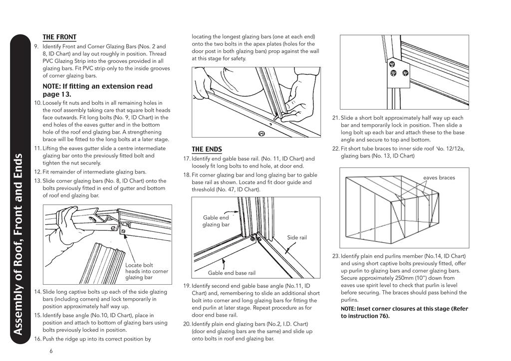
5 ASSEMBLY OF ROOF, FRONT & ENDS NOTE: IDENTIFICATION OF ALL PARTS AND SECTIONS CAN BE FOUND ON THE ID CHARTS (PAGES 14 16). THE ROOF NOTE: If fitting an extension please refer to page Insert short square headed bolts (No. 6 ID chart) into the holes provided in the ridge member and loosely fit nuts. 6. Fit apex plate (No. 7, ID chart) to both ends as shown and tighten securely. 1 Identify the ridge member (no.1 on ID chart), roof glazing bars (No. 2 ID chart), roof end glazing bars (No. 3) and the eaves gutter (No. 4 ID chart). For help with identification, roof glazing bars are the same length as roof end glazing bars. 2 Thread PVC glazing strip (No. 5 ID chart) into the grooves provided on the roof glazing bars and the inside groove only of the roof end bars. Cut to full length taking care not to stretch the PVC strip. A little water or washing up liquid used as a lubricant may help; especially in winter months. 3 Lay out the parts roughly in position with PVC strip facing upwards. ridge glazing bar roof end glazing bar gutter 5. Slide glazing bars and roof end glazing bars onto bolt heads and push home fully. Tighten nuts securely taking care not to over tighten. 7. Slide short bolts into opposite ends of roof glazing bars and roof end glazing bars. 8. Offer up eaves gutter to bolts and, taking care to push fully home, tighten securely both roof glazing bars and roof end glazing bars. Assembly of Roof, Front and Ends 5
6
7 FIXING FRAME TO THE WALL AND SECURING THE BASE The complete frame can now be positioned on its final site and fixed to the wall. 24. Butt completed frame tightly against wall and mark exact vertical position for long glazing bar on wall. It is important at this stage that a spirit level should be used to ensure frame is level and square. 25. Holding the plain end bar in its vertical position, check with spirit level, drill through the centre of the bar with a 5mm twist drill ensuring that this hole lines up with the centre of a brick, not mortar and continues into wall to mark position of hole. Four holes should be made in this way equally spaced starting 6 / 13.5cm from the top and bottom. 26. Pull frame away from wall and fir Sealband strip provided. Cut strip to required lengths, leave a small gap at each hole to allow screws to pass through. Remove backing paper from strips and fit between holes. 27. Now drill the wall with 8mm masonry drill, at the points marked, to at least the depth of the round headed screws. Fit rawplugs supplied. 28. Repeat stages 24 to 27 for long glazing bar at other end. Position frame against the wall loosely fitting screws through the wall glazing bars into the rawplugs. 29. To fix ridge to wall drill 5mm holes top and bottom centrally between each glazing bar. NOTE: A small V groove is provided the length of the ridge to locate your drill tip. continue drilling slightly into the wall to mark position. 30. Remove loosely fitted end glazing bar screws, pull frame with ridge away from wall to enable you to drill all holes marked for the ridge with an 8mm masonry drill (to at least the depth of the screws provided). Fit rawplugs. At this stage it is recommended that the base be secured. 31. Ensure that the frame is square and that the site is level. 32. Identify the base anchors (No.15, I.D. Chart) or base brackets (No.15a, I.D. Chart) and lay out at the base of each glazing bar on the ends and every other glazing bar on the front. (Only one anchor required at each corner - not two.) 33. Dig out a hole below each glazing bar 6 x6 x12 deep and secure base anchors to bolts as shown. 34. Screw both the long glazing bars and the ridge to the wall 35. Now concrete in each anchor and allow to set. Glazing bar 12 Long bolt Base anchor (No.17 I.D.Chart). Note that the bar capping, when butted up against the gutter, will stop short of the glass. This is to allow the next row of sheets to overlap. Continue fitting first sheets to each bay using standard PVC bar capping (No.18 I.D. Chart) for intermediate roof glazing bars and corner capping at the opposite end. 6 GLAZING THE ROOF NOTE: The roof glass is over-lapped NOTE: All bar caps are factory cut to lengths required. Having positioned bottom cap, tap head of bottom screw to ensure it engages in the correct position. 36. With reference to the glazing plan identify roof glass and PVC corner bar capping (No.16 I.D. Chart). Secure in position shown using self tapping screws ASSEMBLING THE VENT 37. Identify the vent kit(s) and assemble with a standard size pane of glass (610 x 610mm). Do not at this stage attach the slam rail assembly, this will be attached when the roof glazing is complete. 38. Fit both side vent members to vent hinge, using M6 x 10 bolts. Slide glass into side vents and into hinge Then fit cill member in place and fix using M6 X 10 bolts. Finally, using No. 8 X 12 self tapping screws, fix at each corner, ensuring the vent hinge closures are in place. On all models use silicone around the perimeter of the glass to seal any gaps, checking first that the vent is square. Wall and Base fixing 7
 nylon brush strip (I.D. chart no.24) NOTE: See separate instruction leaflet in opener box. 39. At this stage, slide first a vent stop (No.22 I.D. Chart), then the assembled vent, followed by a further vent stop, into the groove provided in the ridge.")
 and secure all top sheets up to the vent aperture. All top sheets should be pushed into the ridge member. Fit bar cap covers after securing top sheets. 41.")
 and slide the brush strip along its length, protruding each end by approximately 5mm. Then using standard M6 X 10 bolts and nuts attach the fixing cleats (No.")
 and ensuring that they are located into the glazing bars on either side of the vent, slide rail down onto edge of glass, tighten nuts to secure.")
8 vent side (I.D. chart no.20) vent closure (I.D. chart no.23) vent hinge (I.D. chart no.19) Glazing the Front slam rail cleat (I.D. chart no.27) slam rail assembly cropped head bolts (I.D. chart no.25) vent cill (I.D. chart no.21) nylon brush strip (I.D. chart no.24) NOTE: See separate instruction leaflet in opener box. 39. At this stage, slide first a vent stop (No.22 I.D. Chart), then the assembled vent, followed by a further vent stop, into the groove provided in the ridge. Do not secure at this stage. NOTE: If you are fitting more than one vent per side, slide all vent stops and vents in at this stage. 40. Decide on the position for the vent(s) and secure all top sheets up to the vent aperture. All top sheets should be pushed into the ridge member. Fit bar cap covers after securing top sheets. 41. Position vent over aperture, slide vent stops up each side and secure both stops firmly. 42. Identify the slam rail (from vent kit) and slide the brush strip along its length, protruding each end by approximately 5mm. Then using standard M6 X 10 bolts and nuts attach the fixing cleats (No. 27, ID Chart). Next identify 2 cropped head bolts (No. 25, ID Chart) and ensuring that they are located into the glazing bars on either side of the vent, slide rail down onto edge of glass, tighten nuts to secure. NOTE: See separate instruction leaflet in opener box for full details. GLAZING THE FRONT NOTE: Glass on the front is butt jointed using separator strips 43. With reference to the glazing plan identify glass base panels, PVC standard and corner bar cappings (No. 16 / 18, ID Chart), black or white separator strips for glass (No 26 ID Chart). Bar cappings will be shorter than front glazing bars by 16mm. 44. Starting from one corner, position first base panel fitted with 4mm white or black separator strip. 8


9 Select corner bar capping and secure with bottom self tapping screws (No.17, ID Chart) only at this stage. 45. Continue fitting the base panels finishing the row with another bar capping. 46. With reference to the glazing plan fit the first full row of small glass sheets complete with separator strip and secure with further self tapping screws. 47. Secure panes in position one side only by screwing all self tapping screws into the bar capping and fit bar cap covers (18a I.D. Chart) 48. Repeat instructions 47 until side glazing is complete, finishing the side with a further corner bar capping. 51. With reference to the glazing plan, identify the top angled sheets and fit by pushing up into the roof end bar recess, and align bottom edge with separator strip allowing glass to drop in. Secure all bar cappings. Outside Inside 4mm separator Gutter member Corner bar Corner bar capping GLAZING THE PLAIN END 49. Locate and roughly lay out corner bar cappings and standard cappings. Corner caps are used against the wall. 50. Following established procedure, fit all base panels and all glass panes up to (but not including) the top angled sheets and secure as work proceeds. Top row of glass Base panel PUSH Glazing bar Base panel is 4mm Toughened glass 610 x 305 Roof end bar Push up Separator Strip End glazing bar Glazing the Sides 9
10
11
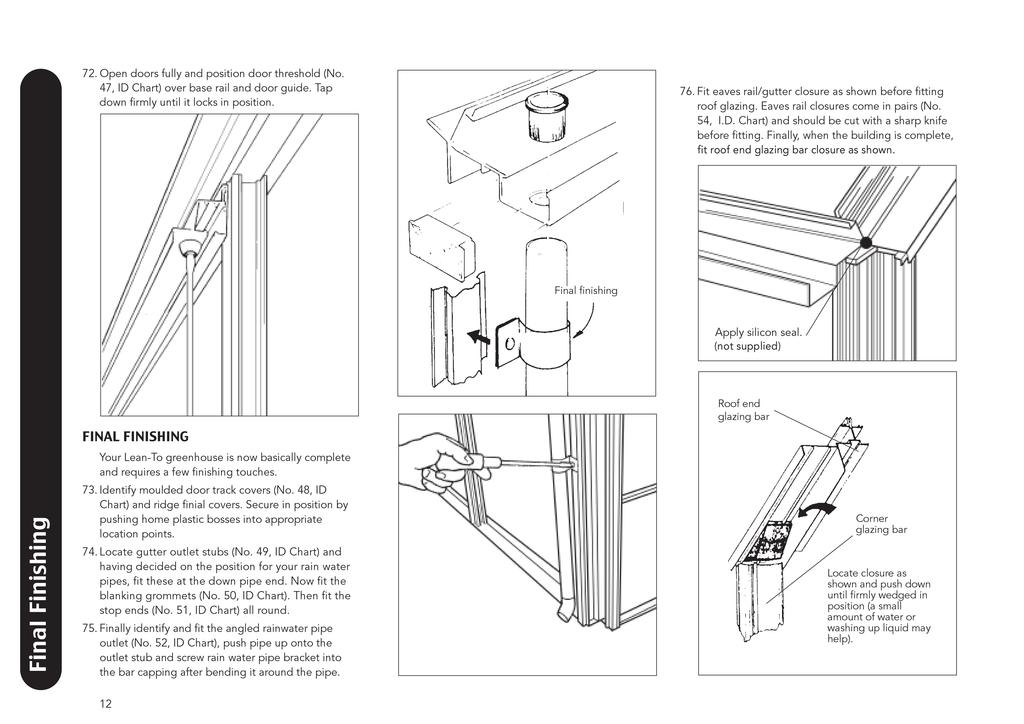
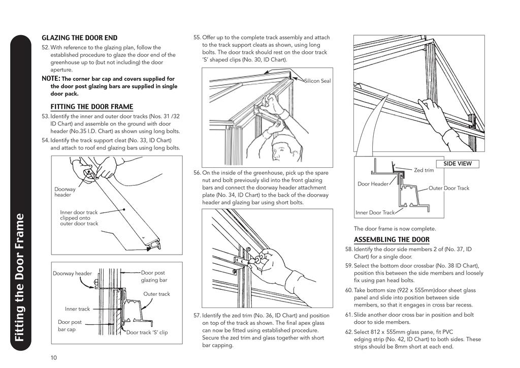
12
13
14 1. Ridge member 5. Eaves gutter 11. Door and plain end gable base rail R Corner bar capping R318 Door Guide (Door End only) DS60 S/D 6. Short square headed bolt F5002 nut F Diagonal brace 1784mm 12a. Gable diagonal brace 1918 mm 17. No 8 x 12mm self tapping Pozidrive screws FS6017 IDENTIFICATION CHART 2. Glazing bar R Roof end glazing bar R PVC glazing strip D Corner glazing bar D Side base rail R Apex gusset plate D Long square headed bolt F5003 nut F5006 inside grooves 14. Plain end purlin member 13. Tube braces 15. Base anchor D106 15a. Base bracket 18. Standard bar capping R316 18a. Bar cap cover R Vent hinge D866 14
15
16
17 D966 D967 D965 D x x 610 vent 610 x 630 plain D966 D968 D D x 1628 D x 1628 D x 1628 D x 1628 D x 1628 D x 1628 D D x x x x x x 305 D1254 D1254 D1254 D1254 D1254 D x 555 D D x 555 D D968
18
 centres. Use the appropriate cleat as indicated.")
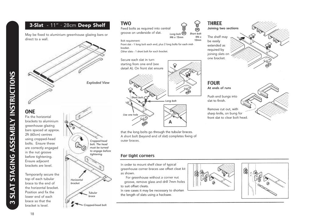
19 7-Slat cm Deep Shelf May be fixed to aluminium greenhouse glazing bars or direct to a wall. Exploded View Greenhouse Fixing Using the nut groove in aluminium glazing bars at approx. 2ft (60cm) centres. Use the appropriate cleat as indicated. ONE Fix the wall cleats using cropped-head bolts (ensuring that they are correctly fully engaged in the nut groove) or using wall plugs and screws as appropriate. Ensure adjacent brackets are level. Cropped-head bolt. The head must be turned to engage before tightening. TWO Fix the horizontal brackets ensuring the flanges close off the ends of the slats. Secure the top end of the tubular brace to the single hole near the end of the bracket. Position and fix the lower end of the brace so that the bracket is level. Horizontal bracket Cropped-head bolt Tubular brace Fixing into greenhouse corners where there is no nut groove The glass must be removed prior to drilling 7mm holes in the glazing bar to accept the offset cleat and tubular brace. This will provide clearance for typical greenhouse bracing. In rare cases it may be necessary to shorten the length of the slats using a hacksaw. THREE Secure slats to the horizontal brackets as shown. The bolt heads slot into the central groove in the Use one hole underside of each slat. Feed in extra bolts, one for each end and one for the centre. Use one hole FOUR The central horizontal bracket is mounted with flat top on to which the slats are fixed. The second of each pair of holes is only used for joining slats (see below). Once all the slats have been assembled, check for squareness and then securely tighten all nuts with a 10mm spanner or nut driver. Joining two sections of staging The offset cleat at the join has to be replaced with small intermediate cleat. The horizontal bracket is then turned over so that the flat top supports the end of the two sets of slats. Secure each slat with a bolt. 7 SLAT STAGING ASSEMBLY INSTRUCTIONS 19
20 10 SLAT STAGING ASSEMBLY INSTRUCTIONS 10-Slat cm Deep Shelf May be fixed to aluminium greenhouse glazing bars or direct to a wall. Extra support is supplied for this staging, It is fixed to the side glazing bar and hooked into the Exploded View side of the staging. This should be done at each end of the staging. Greenhouse Fixing Using the nut groove in aluminium glazing bars at approx. 2ft (60cm) centres. Use the appropriate cleat as indicated. ONE Fix the wall cleats using croppedhead bolts (ensuring that they are correctly fully engaged in the nut groove) or using wall plugs and screws as appropriate. Ensure adjacent brackets are level. TWO Fix the horizontal brackets ensuring the flanges close off the ends of the slats. Secure the top end of the tubular brace to the single hole near the end of the bracket. Position and fix the lower end of the brace so that the bracket is level. Cropped-head bolt. The head must be turned to engage before tightening. Horizontal bracket Cropped-head bolt Tubular brace Fixing into greenhouse corners where there is no nut groove The glass must be removed prior to drilling 7mm holes in the glazing bar to accept the offset cleat and tubular brace. This will provide clearance for typical greenhouse bracing. In rare cases it may be necessary to shorten the length of the slats using a hacksaw. THREE Secure slats to the horizontal brackets as shown. The bolt heads slot into the central groove in the Use one hole underside of each slat. Feed in extra bolts, one for each end and one for the centre. Use one hole FOUR The central horizontal bracket is mounted with flat top on to which the slats are fixed. The second of each pair of holes is only used for joining slats (see below). Once all the slats have been assembled, check for squareness and then securely tighten all nuts with a 10mm spanner or nut driver. Joining two sections of staging The offset cleat at the join has to be replaced with small intermediate cleat. The horizontal bracket is then turned over so that the flat top supports the end of the two sets of slats. Secure each slat with a bolt. 20
21 Louvre Installation Instructions D361 Louvre Kit INSTALLATION 1 Screw self-tapping screws through holes in the top and bottom cill members into the C groove of the side jambs to form a complete frame. No.6 x 12 screws Exploded View Top cill 2 From outside the greenhouse, fit the frame in place, fixing into position using the plastic bar caps and screws. 3 Open the louvre and slide glass blades into position from inside the greenhouse. To avoid excessive movement of glass, bend the retaining clips so that the louvre blade is firmly gripped. CONTENTS OF KIT Part No. Description No. Required - Instructions one D168 Louvre jamb set one D166 Louvre side member two D165 Louvre top/bottom (rubber fitted) one (pair) D362 Louvre smalls pack consisting of: FS 6013 N0.6 x 12 self-tapping screws four D729 T/G Louvre glass x 525mm (4mm thick) six Left hand Side Jamb Left hand Glazing Bar Bottom cill Right hand Side Jamb Right hand Glazing bar (not shown but as left hand bar) LOUVRE INSTALLATION 21
22 Right Angle Corner Plates Right Angle Corner Plates For Right Angle Joining of Slats slide square head bolts into Slat A (one per slat to be joined). Slide one square head bolt (per Slats B ) and secure with Slat corner Joining Plate on underside. Check space between Slats are correct and that Slats B are hard up to Slat A prior to tightening the bolts. NOTE: You may have to reduce the length of Slats B to suit. Right Angle Corner Plates assembly Underside View Slats A Slats B Slat Corner Joining Plate 22
23

24 GROWING BETTER THROUGH DESIGN ROBINSONS GREENHOUSES, STATION WORKS, FENNY COMPTON, SOUTHAM CV47 2XB TELEPHONE FAX Whilst the information contained in this leaflet is accurate at the time of publication, changes in the course of Robinsons policy of improvement through development and design might not be indicated. We point out this fact to avoid any infringements of the Trade Descriptions Act and also to advise that Robinsons Greenhouses reserve the right to change specifications and materials without prior notice. All sizes nominal. All weights approximate. Robinsons Greenhouses 07/08 02/02
GROWING BETTER THROUGH DESIGN LEAN-TO. Lean-To. Assembly Instructions 04/02
 GROWING BETTER THROUGH DESIGN Lean-To LEAN-TO Assembly Instructions 04/02 2 Lean-To Greenhouse Base Plan Introduction / Tools / Contents This is a copy of our Lean-To greenhouse base plan. Dimensions shown
GROWING BETTER THROUGH DESIGN. Regent Royale Rosette Regal GREENHOUSE. Assembly Instructions 04/02
 GROWING BETTER THROUGH DESIGN Regent Royale Rosette Regal GREENHOUSE Assembly Instructions 04/02 Greenhouse Base Plan We cannot emphasis how important it is to have a proper base for your Robinsons Greenhouse
Gardman Lean-to Greenhouse Assembly Instructions
 Page 1 Gardman Lean-to Greenhouse Assembly Instructions Our Help Line provides support and advice to customers of Summer Garden Buildings after ordering. For advice before you buy you can phone us free
Summer Greenhouses 6x8 GREENHOUSE 185. Assembly instructions for the. 6x8 Aluminium Greenhouse 185 PLEASE READ ALL INSTRUCTIONS BEFORE PROCEEDING
 Summer Greenhouses 6x8 GREENHOUSE 185 Assembly instructions for the 6x8 Aluminium Greenhouse 185 PLEASE READ ALL INSTRUCTIONS BEFORE PROCEEDING Summer Greenhouses phone us free on 0800 9777 828 CONTENTS
Greenhouse Assembly Instructions
 Greenhouse Assembly Instructions Our Help Line provides support and advice to customers of Summer Garden Buildings after ordering. For advice before you buy you can phone us free 7 days a week on 0800
A (mm) B (mm) A (mm) B (mm) 12 x x x ft extension. 8ft extension ft extension ft extension 3720
 B (mm) A (mm) B (mm) 12 x x x ft extension. 8ft extension ft extension ft extension 3720") NOMINAL SIZE A (mm) B (mm) NOMINAL SIZE A (mm) B (mm) 12 x 8 2632 6ft extension 1860 12 x 10 3824 3252 12 x 12 3872 8ft extension 2480 10ft extension 3100-12ft extension 3720 Thank you for purchasing your
NOMINAL SIZE A (mm) B (mm) NOMINAL SIZE A (mm) B (mm) 12 x 8 2632 6ft extension 1860 12 x 10 3824 3252 12 x 12 3872 8ft extension 2480 10ft extension 3100-12ft extension 3720 Thank you for purchasing your
6 5 Wide TRADITIONAL CEDAR GREENHOUSE
 6 5 Wide TRADITIONAL CEDAR GREENHOUSE ASSEMBLY INSTRUCTIONS PLEASE READ ALL INSTRUCTIONS BEFORE PROCEEDING 08/04 6 5 WIDE TRADITIONAL CEDAR GREENHOUSE Assembly Instructions Contents Page Introduction 3
6 Wide AMATEUR CEDAR GREENHOUSE
 6 Wide AMATEUR CEDAR GREENHOUSE ASSEMBLY INSTRUCTIONS PLEASE READ ALL INSTRUCTIONS BEFORE PROCEEDING 04/11 6 WIDE AMATEUR CEDAR GREENHOUSE Assembly Instructions Contents Page YOUR NEW GREENHOUSE Introduction
10 Wide AMATEUR CEDAR GREENHOUSE
 10 Wide AMATEUR CEDAR GREENHOUSE ASSEMBLY INSTRUCTIONS PLEASE READ ALL INSTRUCTIONS BEFORE PROCEEDING 04/11 10 WIDE AMATEUR CEDAR GREENHOUSE Assembly Instructions Contents Page YOUR NEW GREENHOUSE Introduction
8 Wide AMATEUR CEDAR GREENHOUSE
 8 Wide AMATEUR CEDAR GREENHOUSE ASSEMBLY INSTRUCTIONS PLEASE READ ALL INSTRUCTIONS BEFORE PROCEEDING 04/11 8 WIDE AMATEUR CEDAR GREENHOUSE Assembly Instructions Contents Page YOUR NEW GREENHOUSE Introduction
 SUPREME WALL GARDEN ASSEMBLY INSTRUCTIONS 24/08/16 www.hallsgreenhouses.com Please refer to website for the most up to date instructions. SAFETY WARNING 1. Always wear protective glasses, shoes, gloves
A (mm) B (mm) A (mm) B (mm) 14 x x x ft extension. 8ft extension ft extension ft extension 3720
 B (mm) A (mm) B (mm) 14 x x x ft extension. 8ft extension ft extension ft extension 3720") NOMINAL SIZE A (mm) B (mm) NOMINAL SIZE A (mm) B (mm) 14 x 8 2610 6ft extension 1860 14 x 10 3230 4450 14 x 12 3850 8ft extension 2480 10ft extension 3100-12ft extension 3720 Thank you for purchasing your
NOMINAL SIZE A (mm) B (mm) NOMINAL SIZE A (mm) B (mm) 14 x 8 2610 6ft extension 1860 14 x 10 3230 4450 14 x 12 3850 8ft extension 2480 10ft extension 3100-12ft extension 3720 Thank you for purchasing your
6 x 6 OCTAGONAL CEDAR GREENHOUSE
 6 x 6 OCTAGONAL CEDAR GREENHOUSE ASSEMBLY INSTRUCTIONS PLEASE READ ALL INSTRUCTIONS BEFORE PROCEEDING 07/2010 6 x 6 OCTAGONAL CEDAR GREENHOUSE Assembly Instructions Contents Page Introduction 3 Safety
Renaissance. Assembly Instructions GREENHOUSE. for models BEFORE OPENING ANY OF THE BOXES PLEASE READ THESE INSTRUCTIONS 03/07
 Renaissance GREENHOUSE ssembly Instructions for models 68 610 612 EFORE OPENING NY OF THE OXES PLESE RED THESE INSTRUCTIONS 03/07 RENISSNCE Greenhouse ase Plan You may have already considered the position
Zero Threshold TM. Hints and Tips Handbook. Birdlip. Burford. Blockley. Bourton
 Birdlip Burford Zero Threshold TM Hints and Tips Handbook Blockley www.edengreenhouses.com Bourton Customer Helpline: +44 (0)1242 676625 Mon Fri 9:00am 5:00pm mail@eden greenhouses.com EH 1.02 Dear Customer,
10 Wide AMATEUR CEDAR GREENHOUSE
 10 Wide AMATEUR CEDAR GREENHOUSE ASSEMBLY INSTRUCTIONS Our Help Line provides support and advice to customers of Summer Greenhouses after ordering. For advice before you buy phone us free 7 days a week
8 Wide AMATEUR CEDAR GREENHOUSE
 8 Wide AMATEUR CEDAR GREENHOUSE ASSEMBLY INSTRUCTIONS Our Help Line provides support and advice to customers of Summer Greenhouses after ordering. For advice before you buy phone us free 7 days a week
Version 2016_1.1 VICTORIAN ASSEMBLY INSTRUCTIONS. Victorian Vi-23, 34, 36
 Version 2016_1.1 VICTORIAN ASSEMBLY INSTRUCTIONS Victorian Vi-23, 34, 36 PRODUCT INFORMATION Dear customer, Thank you for buying a high-quality aluminium greenhouse. REMARKS The drawings in these instructions
NOMINAL SIZE A (mm) B (mm)
 B (mm)") NOMINAL SIZE A (mm) B (mm) x 2012 x 8 232 1972 x 10 3252 x 12 3872 Thank you for purchasing your new Robinsons greenhouse. We recommend you familiarise yourself with the instructions and read all safety
NOMINAL SIZE A (mm) B (mm) x 2012 x 8 232 1972 x 10 3252 x 12 3872 Thank you for purchasing your new Robinsons greenhouse. We recommend you familiarise yourself with the instructions and read all safety
NOMINAL SIZE A (mm) B (mm)
 B (mm)") NOMINAL SIZE A (mm) B (mm) X 1990 X 8 198 210 X 10 3230 X 12 3850 Thank you for purchasing your new Robinsons greenhouse. We recommend you familiarise yourself with the instructions and read all safety
NOMINAL SIZE A (mm) B (mm) X 1990 X 8 198 210 X 10 3230 X 12 3850 Thank you for purchasing your new Robinsons greenhouse. We recommend you familiarise yourself with the instructions and read all safety
46, 66, Page /01/17
 46, 66, 86 46 Only Instructions Page 29-31 www.hallsgreenhouses.com Please refer to website for the most up to date instructions. 05/01/17 333 1106 No. 6 x 16mm Long 711 F B D E C A G I,H J K L M
Installation Guide Simplicity Alfresco. V1.9 Lu070318
 0333 305 5272 www.canoports.co.uk Installation Guide Simplicity Alfresco V1.9 Lu070318 Tools Required Below is a list of tools that you will require to install your the Simplicity Alfresco System. Cordless
NOMINAL SIZE. A (mm) B (mm) 8 X 6 8 X 8 8 X X
 B (mm) 8 X 6 8 X 8 8 X X") NOMINAL SIZE A (mm) B (mm) X 6 1990 X 259 2610 X 10 3230 X 12 350 Thank you for purchasing your new Robinsons greenhouse. We recommend you familiarise yourself with the instructions and read all safety
NOMINAL SIZE A (mm) B (mm) X 6 1990 X 259 2610 X 10 3230 X 12 350 Thank you for purchasing your new Robinsons greenhouse. We recommend you familiarise yourself with the instructions and read all safety
NOMINAL SIZE. A (mm) B (mm) 8 x 6. 8 x x x
 B (mm) 8 x 6. 8 x x x") NOMINAL SIZE A (mm) B (mm) x 6 2012 x 2632 2602 x 10 3252 x 12 372 Thank you for purchasing your new Robinsons greenhouse. We recommend you familiarise yourself with the instructions and read all safety
NOMINAL SIZE A (mm) B (mm) x 6 2012 x 2632 2602 x 10 3252 x 12 372 Thank you for purchasing your new Robinsons greenhouse. We recommend you familiarise yourself with the instructions and read all safety
NOMINAL SIZE A (mm) B (mm)
 B (mm)") NOMINAL SIZE A (mm) B (mm) 11 x 6 2012 11 x 8 2632 3536 11 x 10 3252 11 x 12 3872 Thank you for purchasing your new Robinsons greenhouse. We recommend you familiarise yourself with the instructions and
NOMINAL SIZE A (mm) B (mm) 11 x 6 2012 11 x 8 2632 3536 11 x 10 3252 11 x 12 3872 Thank you for purchasing your new Robinsons greenhouse. We recommend you familiarise yourself with the instructions and
ENGINEERING STRENGTH INSTAL L AT I O N M A NUAL OUR STRENGTH IS OUR STRENGTH
 ENGINEERING STRENGTH INSTAL L AT I O N M A NUAL OUR STRENGTH IS OUR STRENGTH RAFTER PREPERATION RAFTER PREPARATION A FRAME PREPERATION AND ASSEMBLY A FRAME PREPARATION AND ASSEMBLY... Open boxes, remove
E N G L I S H GARDEN SHED. Assembly Instructions. Suitable for Models WITH VARYING DEPTHS
 GARDEN SHED Assembly Instructions Suitable for Models 6' Wide 8' Wide 0' Wide WITH VARYING DEPTHS GI0003 November 0 INSTALLATION ADVICE It's Not That Difficult! The construction of your shed isn't as complicated
CONSTRUCTION GUIDE 27ft Wide and 30ft Wide SHEEP HOUSE
 The Outside, Inside CONSTRUCTION GUIDE 27ft Wide and 30ft Wide SHEEP HOUSE Thank you for purchasing a Premier Sheep House. Please take the time to carefully read through this Construction Guide before
Installation - Sub Cills
 Installation - Sub Cills Fitting of Subcill Drainage paths through the sub-cill can be seen on the illustration alongside so care must be taken to ensure they are not obstructed and that screw fixings
CONSTRUCTION GUIDE 21ft Wide and 24ft Wide SHEEP HOUSE
 The Outside, Inside CONSTRUCTION GUIDE 21ft Wide and 24ft Wide SHEEP HOUSE Thank you for purchasing a Premier Sheep House. Please take the time to carefully read through this Construction Guide before
6 Wide Evolution Cedar Greenhouse Assembly Instructions
 1 02/14 6 Wide Evolution Cedar Greenhouse Assembly Instructions Contents: Introduction Base Preparation Overview Base Assembly Side Assembly Rear Assembly Front Assembly Roof Assembly Louvre Assembly Glazing
8 Wide Victorian Cedar Greenhouse Assembly Instructions
 07/14 09/14 Contents: Introduction Base Preparation Overview Base Assembly Side Assembly Rear Assembly Front Assembly Frame Assembly Door Assembly Roof Assembly Half Board Installation Louvre Installation
8 X 8 Extension ASSEMBLY INSTRUCTIONS TO BE USED IN CONJUNCTION WITH 8 WIDE INSTRUCTUIONS ISSUE: 2
 8 X 8 Extension ASSEMBLY INSTRUCTIONS TO BE USED IN CONJUNCTION WITH 8 WIDE INSTRUCTUIONS ISSUE: 2 Dear Customer, Thank you for ordering your new HERCULES II greenhouse extension from us. We hope you find
SteelChief Installation Instructions for pre-assembled panel form sheds GABLE ROOF
 SteelChief Installation Instructions for pre-assembled panel form sheds GABLE ROOF Please read fully before commencing work...any queries will be promptly answered, contact theboss@steelchief.com.aui MPORTANT
10 Wide Victorian Cedar Greenhouse Assembly Instructions
 06/15 10 Wide Victorian Cedar Greenhouse Assembly Instructions Contents: Introduction Base Preparation Overview Base Assembly Side Assembly Rear Assembly Front Assembly Frame Assembly Door Assembly Roof
16ft Polytunnel Assembly Instructions
 CONTENTS Section Page 1. FOUNDATION TUBES: Option A Ground Anchor Plates 3 2. FOUNDATION TUBES: Option B Concreted Foundation Tubes 5 3. STEEL FRAME ASSEMBLY & INSTALLATION 6 4. CROP BARS 8 5. TIMBER END
GREENHOUSE 6'x8' ASSEMBLY INSTRUCTIONS. (Internal Dimensions) Overall Dimensions (Approx.) L 193 W 200 H cms 97.5" L 76" W 78.
 Overall Dimensions (Approx.) L 193 W 200 H cms 97.5 L 76 W 78.") ASSEMBLY INSTRUCTIONS GREENHOUSE 'x8' (Internal Dimensions) Overall Dimensions (Approx.) 7. L 9 W 00 H cms 97." L 7" W 78.8" H 0 IMPORTANT You must read these instructions carefully before you start to
ASSEMBLY INSTRUCTIONS GREENHOUSE 'x8' (Internal Dimensions) Overall Dimensions (Approx.) 7. L 9 W 00 H cms 97." L 7" W 78.8" H 0 IMPORTANT You must read these instructions carefully before you start to
Extension Standard building 03/15
 Extension Standard building 03/15 8 Wide Evolution Extension Assembly Instructions Contents: Introduction Base Preparation Overview Base Assembly Side Assembly Front Assembly Extension Installation Rear
S H E D A S S E M B L Y I N S T R U C T I O N S
 T I T A N R A N G E S H E D A S S E M B L Y I N S T R U C T I O N S 8 X 10 ft Approx = 2550 x 3140 cm COMPONENT LIST Component illustrations are given as a visual guide only and are not in proportion PART
IMPORTANT!!! ASSEMBLY ASSEMBLY INSTRUCTIONS. (Internal Dimensions)
") ASSEMBLY ASSEMBLY INSTRUCTIONS (Internal Dimensions) Ent Spec Edition Ltr v-0- Overall dimensions including base: 7. L x 9 W x 0 H cms 97.5" L x 7" W x 8.7" H IMPORTANT!!! Please read these instructions
ASSEMBLY ASSEMBLY INSTRUCTIONS (Internal Dimensions) Ent Spec Edition Ltr v-0- Overall dimensions including base: 7. L x 9 W x 0 H cms 97.5" L x 7" W x 8.7" H IMPORTANT!!! Please read these instructions
Installation Guide Contemporary Alfresco V1.3 LU
 Installation Guide Contemporary Alfresco V1.3 LU 010818 Tools Required Below is a list of tools that you will require to install you're the Contemporary Alfresco System. Cordless Drill Mastic Gun Spirit
Extension Standard building 10/14
 Standard building Extension 10/14 8 Wide Victorian Cedar Greenhouse Extension Assembly Instructions Contents: Introduction Base Preparation Overview Base Assembly Side Assembly Frame Assembly Door Installation
Safety Glasses Safety Gloves Ladders Measuring Tape Spirit Level String Line. Tin-Snips Rivet Gun Caulking Gun Silicone Socket Set
 BEFORE YOU START Carefully read these instructions and refer to them constantly during each stage of construction. If you do not have all the necessary tools or information, contact Stratco for advice.
DUTCH GABLE FREESTANDING CARPORT
 DUTCH GABLE FREESTANDING CARPORT STRATCO OUTBACK ASSEMBLY INSTRUCTIONS. Your complete guide to building a FREESTANDING Outback DUTCH GABLE CARPORT BEFORE YOU START Carefully read these instructions. If
Oxford Stalls Installation Instructions
 Oxford Stalls Installation Instructions RAMM Horse Fencing and Stalls 13150 Airport Hwy. Swanton, OH 43558-9615 1-800-434-8456 Rev. 8/15/17 Before You Start Typical stall sizes are 10 x 10, 12 x 12 or
12ft Ultra Polytunnel Assembly Instructions
 CONTENTS Section Page 1. FOUNDATION TUBES: Option A Hammered-In Foundation Tubes 3 2. FOUNDATION TUBES: Option B Ground Anchor Plates 4 3. FOUNDATION TUBES: Option C Concreted Foundation Tubes 5 4. STEEL
INSTALLATION INSTRUCTIONS DANUBE ACRYLIC NEO ANGLE
 INSTALLATION INSTRUCTIONS DANUBE ACRYLIC NEO ANGLE March 2013 DOOR 2 Page 1 of 5 INSTALLATION INSTRUCTIONS NEO ANGLE 6MM FRAMELESS AND 4MM FRAMED SHOWER DOOR DANUBE, DELTA, SIGNATURE, OCEANIA, CASCADE
ASSEMBLY INSTRUCTIONS FOR STORETTE STA42
 ASSEMBLY INSTRUCTIONS FOR STORETTE STA42 A01 CAUTION: Some parts have sharp edges. Care must be taken when handling the various pieces to avoid a mishap. For safety sake, please read the safety information
S H E D A S S E M B L Y I N S T R U C T I O N S
 T I T A N R A N G E S H E D A S S E M B L Y I N S T R U C T I O N S 6 X 4ft = 190 x 150 cm 6 X 6ft = 190 x 190 cm 6 X 8ft = 190 x 255 cm COMPONENT LIST Component illustrations are given as a visual guide
10 Wide Victorian Cedar Greenhouse Assembly Instructions
 12/15 10 Wide Victorian Cedar Greenhouse Assembly Instructions Contents: Introduction Overview Base Preparation Side Assembly Rear Assembly Front Assembly Frame Assembly Door Installation Roof Assembly
STRATCO GABLE HOMESHED STRATCO GABLE HOMESHEDS STUBBIE INSTALLATION GUIDE
 STRATCO GABLE HOMESHED STRATCO GABLE HOMESHEDS STUBBIE INSTALLATION GUIDE INSTALL GUIDE BEFORE YOU START COUNCIL APPROVAL It is important that you have local council approval before building your Stratco
Liniar Window. installation guide
 Liniar Window installation guide This installation guide is designed to show you the best way to fit Liniar windows, and covers all styles of window made from Liniar s lead-free 70mm PVCu profile. Not
CONSERVATORY ROOF INSTALLATION GUIDE Issue
 CONSERVATORY ROOF INSTALLATION GUIDE Issue 3 CONTENTS 1. Statements 2. General assemblies 3. Victorian / Edwardian roof installation 4. Jack rafter installation 5. P-shaped roof installation 6. Lean-to
8 Wide Evolution Cedar Greenhouse Assembly Instructions
 02/14 8 Wide Evolution Cedar Greenhouse Assembly Instructions Contents: Introduction Base Preparation Overview Base Assembly Side Assembly Rear Assembly Front Assembly Roof Assembly Louvre Assembly Glazing
STORAGE & SHELVING SYSTEM - INSTALLATION GUIDE
 STORAGE & SHELVING SYSTEM - INSTALLATION GUIDE If you have ordered storage drawers, shelving, hanging rails or shoe racks this guide will help you install your storage and shelving system, together with
6 Wide Victorian Cedar Greenhouse Assembly Instructions
 04/15 6 Wide Victorian Cedar Greenhouse Assembly Instructions Contents: Introduction Base Preparation Overview Base Assembly Side Assembly Rear Assembly Front Assembly Frame Assembly Door Assembly Roof
TrendWall Floor-To-Ceiling Panels Installation Instruction
 TrendWall Floor-To-Ceiling Panels Installation Instruction TrendWall Components Covered by this Instruction: Crown (and accessories) Floor Plate Solid Panel Filler Panel Wall Channel Door Section Pilaster
8 Wide Victorian Cedar Greenhouse Assembly Instructions
 09/14 8 Wide Victorian Cedar Greenhouse Assembly Instructions Contents: Introduction Base Preparation Overview Base Assembly Side Assembly Rear Assembly Front Assembly Frame Assembly Door Assembly Roof
INSTALLATION GUIDE SLIMLINE ROOF LANTERN 4 PANE CONFIGURATION
 INSTALLATION GUIDE SLIMLINE ROOF LANTERN 4 PANE CONFIGURATION SLIMLINE STEP-BY-STEP INSTALLATION GUIDE Thank you for choosing Roof Maker, we hope you are delighted with your new rooflight. Our roof lanterns
6 Wide Victorian Cedar Greenhouse Assembly Instructions
 01/15 6 Wide Victorian Cedar Greenhouse Assembly Instructions Contents: Introduction Overview Base Preparation Side Assembly Rear Assembly Front Assembly Frame Assembly Door Installation Roof Assembly
CROWN IMPERIAL ASSEMBLY INSTRUCTIONS
 CROWN IMPERIAL ASSEMBLY INSTRUCTIONS Standard Drawer Box Page 1 of 14 Standard Drawer Box Parts Parts Supplied B C D A E F G Page 2 of 14 Part Letter Part Name Quantity 300-600 Deep Pan A Base Panel 1
6 Wide Victorian Cedar Greenhouse Assembly Instructions
 01/15 6 Wide Victorian Cedar Greenhouse Assembly Instructions Contents: Introduction Base Preparation Overview Base Assembly Side Assembly Rear Assembly Front Assembly Frame Assembly Door Assembly Roof
Corner Potting Store Assembly Instructions
 Corner Potting Store Assembly Instructions English SS225E Before assembly We recommend that time is taken to read the instructions before starting assembly, then follow the easy step by step guide. The
Eurocell conservatory roof system. Installation manual Issue 3
 Eurocell conservatory roof system Installation manual Contents Statement General Assemblies Cross Sections Victorian/ Edwardian Roof Installation Jack Rafter Installation P Shape Roof Installation 15-45
Allora ALCOVE ENCLOSURE INSTALLATION BEFORE INSTALLATION CHECK THAT YOUR ALLORA SHOWER ENCLOSURE SYSTEM IS UNDAMAGED
 Allora ALCOVE ENCLOSURE INSTALLATION BEFORE INSTALLATION CHECK THAT YOUR ALLORA SHOWER ENCLOSURE SYSTEM IS UNDAMAGED ALCOVE SHOWER Your shower can be installed to open Left hand or Right hand by rotating
Additional help from 'The Greenhouse People'.
 Additional help from 'The Greenhouse People'. Please read all information before you begin, some of the tips and techniques may save you a lot of time and frustration later on. These help sheets should
Installation Guide Simplicity 16. V2.9 Lu171117
 0845 869 6006 www.canoports.co.uk Installation Guide Simplicity 16 V2.9 Lu171117 Tools Required Below is a list of tools that you will require to install the Simplicity 16 Canopy or Carport. Cordless Drill
method of build Komfire-75 partitioning system 75mm Steel Stud & Plasterboard Partitioning System with Square Aluminium Cover Trims KOMFORT
 821 811 342 821 835 853 863 840 12.5mm Plasterboard 837 75mm Steel Stud & Plasterboard Partitioning System with Square Aluminium Cover Trims Note: For clarity the cavity infill has not been shown 854 342
Fig. 2 DORMA-Glas Stand/Issue 02/03 Seite/Page 1/7
 FSW Installation instructions Track rail 75 x 72 mm 1. Ceiling substructure and installation of the track rail (Fig. 1): The track rail must be bolted over its entire length (including the stacking track
REGENCY TIMBER BUILDINGS
 REGENCY TIMBER BUILDINGS TEL 01948 830460 UNIT 22 PENLEY IND EST, PENLEY.WREXHAM. LL13 0LQ 1 Garage fitting instructions Tools needed handsaw, hammer, Stanley knife with hook blade, tape measure, battery
Walk-in Greenhouse. Assembly instructions. 8x6. 8x8. 8x10. 8x12. Model GH1399A Model GH1400A. Model GH1402A Model GH1403A. Model GH1405A Model GH1406A
 Assembly instructions 8x6 Model GH1399A Model GH1400A 8x8 Model GH1402A Model GH1403A 8x10 Model GH1405A Model GH1406A 8x12 Model GH1408A Model GH1409A Walk-in Greenhouse Statement Dear Customer! May we
 For Wallbed models: KING SIZE INSTRUCTION BOOKLET #C1 Watch step by step installation instructions at: https://www.wallbedsbywilding.com/wallbed-installation-studio-series/ WARNING! ALL MURPHY/WALLBED
Assembly Instructions
 10' and 12' Octagon Cedar Gazebo Assembly Instructions Toll Free: 866.768.8465 Hours: 9-5 Monday-Friday EST www.homeplacestructures.com Package ships as shown revised 06/20/09 Cedar Gazebo Assembly Instructions
Cold Frame Instructions
 1 05/13 Cold Frame Instructions Thank you for purchasing your new Alton cold frame. We recommend you familiarise yourself with the instructions and read all safety information before you commence assembly.
SLIDING MECHANISM TROLLEY CATCH TROLLEY ASSEMBLY FLOOR GUIDE
 Set A Set B P7001 Standard Kit FITTING INSTRUCTIONS For use with 44mm thick doors only For Single and Double doors IF INSTALLING A TOUCH LATCH, PLEASE READ THE CORRESPONDING FITTING INSTRUCTIONS FIRST
HOUSE PARTS PACKED IN HOUSE BOX PARTS IN PLASTIC BAG (HARDWARE) PARTS IN SMALL PLASTIC BAG (FLOOR CLIPS) PARTS PACKED IN BUNDLE
 PARTS IN SMALL PLASTIC BAG (FLOOR CLIPS) PARTS PACKED IN BUNDLE") Check parts against this list before starting assembly. Refer to illustrations on pages 6 and 7 to view house parts. If any shortages are found, refer to Packing Slip for claim instructions. Item 3 5 6
Check parts against this list before starting assembly. Refer to illustrations on pages 6 and 7 to view house parts. If any shortages are found, refer to Packing Slip for claim instructions. Item 3 5 6
Deauville Installation Guide
 vjul16 (for 17 or 24 mm Surface Wall Profiles) DO NOT ASSEMBLE WITHOUT FULLY READING THESE INSTRUCTIONS Page 2 Thank you for purchasing this Deauville shower enclosure. Please study these instructions
Installation Guide. Evolve bi-fold. 8. Door restrictor- optional p9. 1. Before you start p2. 9. Adjustment. 2. Measuring and surveying p2
 Evolve bi-fold Installation Guide 1. Before you start p2 8. Door restrictor- optional p9 2. Measuring and surveying p2 3. Configuration details p4 4. Installation p5 5. Glazing p5 6. Glazing packer details
WARNING Please refer to all safety notices in the greenhouse manual before assembling any of the sections
 Billy Oh Rosette Green House Assembly Hints and Tips WARNING Please refer to all safety notices in the greenhouse manual before assembling any of the sections TOP TIPS 1. These instructions are generic
Qwik-Fence Installation Instructions
 Qwik-Fence Installation Instructions 1 Tools Required The following installation instructions should be used as a guide for installing Folding Guard Qwik-Fence Partitions. Good common sense and appropriate
Installation Guide. Bi-fold Doors
 Installation Guide Bi-fold Doors Installation Guide Components box 1. 6. 2. 3. 7. 5. 4. 8. Contents 1. Fixing plugs 2. Wedge gasket 3. Bottom trolley 4. Top trolley 5. Magnetic keep (x 2 if door height
Portofino Installation Guide
 vjul16 (for 17 or 24 mm Surface Wall Profiles) DO NOT ASSEMBLE WITHOUT FULLY READING THESE INSTRUCTIONS Page 2 Thank you for purchasing this Portofino shower enclosure. Please study these instructions
GREENHOUSE EXTENSION 6 X4
 ASSEMBLY INSTRUCTIONS GREENHOUSE EXTENSION 6 X Overall Dimensions (Approx.) 0 L x 93 W x 00 H cms 9" L x 76" W x 8.7" H 0 IMPORTANT You must read these instructions carefully before you start to assemble
SLIDING MECHANISM TROLLEY CATCH TROLLEY ASSEMBLY FLOOR GUIDE
 Set A Set B PFD30 Fire Door Kit FITTING INSTRUCTIONS For use with 44mm thick doors only For Single and Double doors IF INSTALLING A TOUCH LATCH, PLEASE READ THE CORRESPONDING FITTING INSTRUCTIONS FIRST
https://www.wallbedsbywilding.com/wallbed-installation-studio-series/
 For Wallbed models: KING SIZE INSTRUCTION BOOKLET #C1 Watch step by step installation instructions at: https://www.wallbedsbywilding.com/wallbed-installation-studio-series/ WARNING! ALL MURPHY/WALLBED
Potting Store Assembly Instructions
 Before assembly We recommend that time is taken to read the instructions before starting assembly, then follow the easy step by step guide. The instruction sheet is only a guide to the assembly. Certain
GrowSpan Estate Pro I Greenhouse
 GrowSpan Estate Pro I Greenhouse Photo may show a different but similar model. 2016 Growers Supply All Rights Reserved. Reproduction is prohibited without permission. STK# DIMENSIONS 104564 11'-8" W x
Installation Guide Simplicity 6. v3.5 lu171117
 0845 869 6006 www.canoports.co.uk Installation Guide Simplicity 6 v3.5 lu171117 Tools Required Below is a list of tools that you will require to install the Simplicity 6 Canopy or Carport. Cordless Drill
Dubnium 11 Installation Instructions & Parts List
 Dubnium 11 Installation Instructions & Parts List Illustration Dubnium, H1 Handle Right Hand: Open Out Page 1 of 25 IMPORTANT This shower screen / enclosure must be installed by suitably qualified individuals.
Sauna & Steam. Traditional Sauna Installation Instruction Manual
 Traditional Sauna Installation Instruction Manual Oceanic Ltd, Pountney Street, Wolverhampton, WV2 4HX Phone: 01902 450 550 sales@oceanic-saunas.co.uk www.oceanic-saunas.co.uk Contents 1.Introduction................................................
utopia Window & Door Products Orangery Home Extension Products Conservatory Products Skylight Products
 Window & Door Products Orangery Home Extension Products Conservatory Products Skylight Products utopia Installation Guide Version 1.1 June 2011 Dear Customer, Thank you for choosing the Ultraframe Utopia
INSTALLATION GUIDE. Flat Roof Homesheds TM. Onto Concrete BEFORE YOU START TOOLS REQUIRED
 INSTALLATION GUIDE Flat Roof Homesheds TM Onto Concrete BEFORE YOU START It is important to check your Local Government Authority requirements before the installation of your new Stratco Flat Roof Homeshed.
Portofino Case2 Installation Guide
 Portofino Case2 Installation Guide vjun16 (for 17 or 24 mm Surface Wall Profile) DO NOT ASSEMBLE WITHOUT FULLY READING THESE INSTRUCTIONS Page 2 Thank you for purchasing this Portofino Case 2 shower enclosure.
Step by Step Installation Instructions. Poly Shutters. Customer Service or visit us online at smithandnoble.com
 Step by Step Installation Instructions Poly Shutters Customer Service 800.248.8888 or visit us online at smithandnoble.com Thank you for purchasing from smith+noble. Your new window treatments have been
Walk-in Greenhouse. Assembly instructions. 6x4. 6x6. 6x8. Model GH0490 Model GH0491 Model GH1040. Model GH0492 Model GH0493 Model GH1041
 ssembly instructions x4 Model GH0490 Model GH049 Model GH040 x Model GH049 Model GH049 Model GH04 x Model GH0494 Model GH049 Model GH04 Walk-in Greenhouse Statement Congratulations on purchasing your new
Clopay Models 835/837 Sliding Door System Installation Guide
 Clopay Models 835/837 Sliding Door System Installation Guide The aim of this instruction is to guide you through the process of construction and fitting of Sliding Doors. Due to the number of sizes available
Laminate Cabinet Installation Instructions
 Laminate Cabinet Installation Instructions www.easygaragestorage.com/installation How To Use These Instructions Thank you for your purchase! Please read each step of this manual thoroughly to ensure proper
INFINITE RANGE - HINGE DOOR
 INFINITE RANGE - HINGE DOOR HINGE DOOR + 1 SIDE RETURN PANEL (CORNER) Please read these instructions before installing, as incorrect fitting will invalidate the guarantee-carry out each stage before moving
ASSEMBLY INSTRUCTIONS DIY WALL BED KIT QUEEN BI FOLD DOOR CABINET & MECHANISM. Tools Required For Assembly. 6.5mm Masonry Drill Bit
 ASSEMBLY INSTRUCTIONS DIY WALL BED KIT QUEEN BI FOLD DOOR CABINET & MECHANISM Tools Required For Assembly No 2 & No 4 Phillips Head Screwdrivers No 2 Slot Head Screwdriver Hammer Electric Drill (Hammer
Gambrel Barn Construction Manual 8x8 through 16x24 Units
 Gambrel Barn Construction Manual 8x8 through 16x24 Units Tools Needed: Cordless drill (12V or higher) #2 square drive bit Hammer 6 step ladder Tape measure Square utility knife w/ blade & hook blade Little