Assembly Instructions for a Double Climbing Frame
|
|
|
- Georgina Bryant
- 5 years ago
- Views:
Transcription

1 Assembly Instructions for a Double Climbing Frame Step A: Lay out both bases with 8ft of spacing between them (See Diagram X) Once you are happy with the position of each base, remove bases and follow instruction steps 1-8 on assembly instructions for the 5ft Climbing Frame pg. 1
2 Assembly instructions for 5 foot climbing frame Materials provided: 4 x 10ft posts cut at an angle of 40 degrees 2 x 10ft posts cut at an angle of 60 degrees (with the top already prepared for the swing pole) 1 x 10ft post for the swing pole 2 x 1274mm posts 2 x 6ftx4ft fence panels 4 x v boards for roof module 1 x steps 1 x 1460x1460 base 3 x 1274mm 3 x1 ½ timber 2 x 1460mm 3 x1 ½ timber 4 sets of railings 1 x rock wall Handgrips 10ft slide 6 x o hooks Telescope Steering wheel Swing seats Hole covers Assortment of screws pg. 2
3 Step1: Ground Preparation Lay out the base, slide and the 10ft swing pole in the position that you intend the climbing frames to be placed. Allow for 6 ft clearance beyond the end of the slide and 4 ft clearance for the steps, rock module and swing module. Once you are happy that the layout is correct, remove the swing pole, steps and rock wall and slide. Mark out clearly all 4 ends of the base area If the climbing frame is on a level surface then dig 4 holes of diameter 12 and depth 12. The tricky part is when the surface is uneven; in this case you would have to compensate for the slope by making some holes deeper than others (minimum depth of 12 ). The bottom of all 4 holes need to be level Step2: Base Preparation Lay 2 of the 10ft posts that are cut at the 40% angle on a level surface Ensure the cut angle is facing the same way on both posts and that the 19mm holes (about halfway up) are facing outwards Now place the 1274mm 4 x4 post between the 2 larger posts Line up the markings as shown below pg. 3
4 Now with the 200mm index screws provided, screw the poles together on both sides, making sure the index screw is tightened into place Make a mark 900mm from the bottom of both 10ft posts Using the 1460mm 3 x1 1/12 timber and using the 50mm decking screws screw the timber to the frame (this is to strengthen the H-frame structure, without this additional support at the bottom the frame will twist once it is lifted up) Repeat the above steps for the 2 nd H-frame Step 3: Base assembly (requires heavy lifting, please use at least 2 people) Lift both H -frames into the holes that have been cut out in the ground Make sure the tops of these H -frames have the correct angle pointing in (to ensure that the roof will be able to rest on the tops) To ensure that the base fits into place use the 1274mm 3x1 ½ timber provided to connect the 2 H -frames together pg. 4
5 The structure should now be able to stand on it s own Lift the base and place it in it s place Secure base using the 120mm screws provided, they are to be screwed directly into the base onto the 4 x4 cross posts Step 4: Side-rails assembly There are 2 open and 2 closed rails. The open ones are for the steps and slide and the closed ones are for the rock module and swing module. They should fit tightly into place between the upright posts and on the base. The double timbers on the side-rails should be on top and the single timber should be at the bottom Secure the bottom rail to the base using decking screws pg. 5
6 Using a 19mm drill bit, drill a hole on the outside of the post as indicated on Diagram C Using the 120mm screws, screw through the upright post so as to tighten the top railing to the post Repeat for all the side-rails Step 5: Roof assembly (See Appendix A) Place one of the 6ftx4ft panels directly onto the ground (so that the shingled part is facing downwards) Using the v boards provided assemble the roof Lift the roof onto the climbing frame and ensure it is level before securing the roof to the top of the post using 2 x decking screws per post pg. 6
7 Step 6: Swing module assembly Lay the 2 x 10ft posts (with the ends cut off at 60 degrees) on a flat surface Place the ends together so that it forms a v-shape Using the 200mm index screws, tighten the ends together Measure down from the top of the v post 1100mm to both posts and place the 1274mm 3 x1 ½ timber across both posts and secure these into place with decking screws pg. 7
8 Using the remaining 10ft post (that is square on both ends) mark out equidistantly where the swings are to be placed. Leave 600mm per swing Once these have been marked, using a 10mm drill bit, drill a hole right through the timber Place each o -hook through these holes, secure using the appropriate spanner Now the tricky part. The v -frame is designed to be at a 10 degree angle (i.e it is not at 90 degrees to the surface). This is best achieved by measuring 11 ft from the end of the climbing frame to the base of the v-frame. The v -frame should be then lined up to the centre of the frame The holes on the ground should then be marked and the v -frame should be sunk into it s place so that the swing bar is level Once this is achieved (no easy task), then secure both ends into place pg. 8
9 Step 7: Concreting structure Using postcrete and following the manufacturers instruction concrete all 6 posts into the ground Once dry you can continue Step 8: Final assembly The steps might have to cut or dug into place (depending on the slope of your surface) They are secured using decking screws Grab handles are then placed on the top of the steps The rock wall is also to be cut or dug into place (typically the rock wall and steps are slightly longer than you require to allow for slopes etc) The rock wall is then screwed into place using the 50mm decking screws Finally place the telescope and steering wheel in a position that suits your garden pg. 9
 place these horizontally")
10 Step 9: Rope Bridge Using the 9ft lengths of 3x1 1/2 (that is doubled up) place these on the underside of the bases. They are to be placed 150mm to the left and right of the centre point of the base Screw these in using 120mm screws provided Using the 1274mm 3x1 1/12 (that is doubled up) place these horizontally below the base as per diagram G below Drill 19mm holes on the outside of the main posts and screw these in using 120mm screws provided You are now ready to screw on the decking boards for the rope bridge and attach the rope and safety netting pg. 10


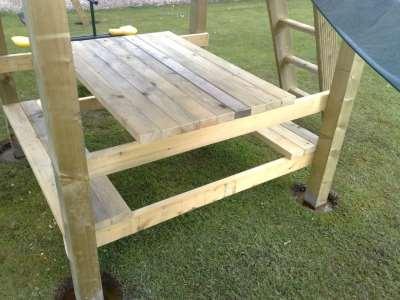
11 Photos that might be useful in building the climbing frame: pg. 11


12 pg. 12

13 pg. 13
Assembly Instructions for a Double Climbing Frame
 Assembly Instructions for a Double Climbing Frame Step 1: Lay out both bases with 8ft of spacing between them (See Diagram Below) Once you are happy with the position of each base, remove bases and follow
Section 1 Safety working at height
 Contents Section 1 Safety working at height. Section 2 Hi-Step package contents & parts identification. Section 3 Assembly. Section 4 Operation. Section 5 Maintenance. Section 6 Extender package contents
Greenhouse Assembly Instructions
 Greenhouse Assembly Instructions Our Help Line provides support and advice to customers of Summer Garden Buildings after ordering. For advice before you buy you can phone us free 7 days a week on 0800
The Festival Assembly Instructions
 The Festival Assembly Instructions Toll Free: 866.768.8465 Hours: 9-5 Monday-Friday EST www.homeplacestructures.com Package ships as shown CONTACT INFORMATION: HomePlace Structures 301 Commerce Drive New
Gardman Lean-to Greenhouse Assembly Instructions
 Page 1 Gardman Lean-to Greenhouse Assembly Instructions Our Help Line provides support and advice to customers of Summer Garden Buildings after ordering. For advice before you buy you can phone us free
Installation Fence Guide Kodiak Iron. Exceptional Fencing Extraodinary Customer Service
 Installation Fence Guide Kodiak Iron Exceptional Fencing Extraodinary Customer Service Kodiak Fence System Installation Guide Thank you for the purchasing the Kodiak Fence System. Fence installation is
Art Thatch TM Umbrella Kit Installation Guide
 Art Thatch TM Umbrella Kit Installation Guide www.artificialthatch.com (858) 643-9030 sales@artthatch.com Parts List Part # Description Name Qty. #1 Main Frame 1 #2 Small Cross Bar 8 #3 Medium Cross Bar
Residential & Industrial Fence
 Residential & Industrial Fence Assembly Instructions CONTENTS 02: OVERVIEW & CONTENTS 03: PRODUCT SPECIFICATIONS 04: GETTING STARTED 05: WALL ATTACHMENT & LINE POST ASSEMBLY 06: CORNER POST ASSEMBLY 07:
Strata. urniture. Addison Instructions. Parts in the Arm Box: Parts in the Body Box: Watch our assembly videos at
 1A Watch our assembly videos at www.strataf.com/videos.html Parts in the Arm Box: Arm - Outside View Arm - Inside View Corbels x 4 1B Parts in the Body Box: Back Deck x 1 Seat Deck x 1 Back Panel x 1 with
Queen Wingback Bed King Wingback Bed
 Parts and Hardware List A. Side Rails with Attachment Hooks 2 pcs B. Foot Rail 1 pc C. Head Rail 1 pc D. Center Support Slat 1 pc E. Leg Supports 3 pcs F. Support Slats 4 pcs G. Flat Washers 8 pcs H. Lock
Extendable Swing Shut Gate
 Extendable Swing Shut Gate WIDTH Adjustable from 72.5 to 95 cm HEIGHT Top of gate to floor 78 cm SPINDLES x 4 WALL CUPS x4 7cm EXTENSIONS x2 GATE NUTS x 4 SPANNER x Note: Each 7cm extension comprises of
Bunk Pod Front Entry Assembly Instructions
 Bunk Pod Front Entry Assembly Instructions www.podtime.co.uk enquiries@podtime.co.uk Working House Ltd How to assemble your pod This step by step guide will show how to assemble your pod(s) on site. It
CONTENTS TOOL LIST U P S I D E I N N O V A T I O N S, L L C RAMP AND STEP SYSTEM ASSEMBLY INSTRUCTIONS. Revised: June 2013
 U P S I D E I N N O V A T I O N S, L L C RAMP AND STEP SYSTEM ASSEMBLY INSTRUCTIONS TOOL LIST Required Tools: - Reciprocating Saw with Metal Cutting Blade - Drill - 7/16 Drill Bit for Metal Drilling -
Regency Railing. Rail Installation Instructions
 Regency Railing Rail Installation Instructions Prior to installing railing: Please consult local zoning laws in regards to load requirements and bottom space requirements for rails. All supporting structures
SAM. Model: STV-C65 LCD Mobile Visualized Stand Instruction Manual. Weight Capacity: 1251bs / 56.7kg Suits LCD Flat Panel Display: 42"-55" Page 20
 SAM Model: STV-C65 LCD Mobile Visualized Stand Instruction Manual Weight Capacity: 1251bs / 56.7kg Suits LCD Flat Panel Display: 42"-55" 20 Step 6 LCD Mobile Lift Stand Model: STV-C65 Cable management
D HANDRAIL. Doc No. A-39. Item Description. Hand hold for deck entry or exit equipment. Available in 0.6M, 0.9M, 1.2M, 1.5M and 1.8M heights.
 D HANDRAIL 1 D Handrail 1 2 M10 Flat Washer 2 Materials: 3 M10x25mm Torx Bolt 2 Hand hold for deck entry or exit equipment. Available in 0.6M, 0.9M, 1.2M, 1.5M and 1.8M heights. 1. Refer to drawings for
6 x 6 OCTAGONAL CEDAR GREENHOUSE
 6 x 6 OCTAGONAL CEDAR GREENHOUSE ASSEMBLY INSTRUCTIONS PLEASE READ ALL INSTRUCTIONS BEFORE PROCEEDING 07/2010 6 x 6 OCTAGONAL CEDAR GREENHOUSE Assembly Instructions Contents Page Introduction 3 Safety
U. M. ARMY Texas Conference. Wheel Chair Ramp Manual
 U. M. ARMY Texas Conference Wheel Chair Ramp Manual June 2014 U. M. ARMY Texas Conference Building & Repair Tips Wheelchair Ramps Complete a site survey to determine the design and layout of the ramp.
Constable Oak Extension Dining Table
 Constable Oak Extension Dining Table Assembly Instructions - Please keep for future reference 176/0325 Dimensions Width - 160/ 200cm Depth - 90cm Height - 75cm Important - Please read these instructions
Assembly Instructions
 Selling Station Assembly Instructions View from above without top A B C D Rounded finished corners on A & D Square unfinished 3-sides on B & C Selling Station Components (2) 2' x 6' Side s Have a channel
INSTALLATION OF THE TRACK FOR THE STRAIGHT SIDE STEEL LADDER
 ASSEMBLY OF THE 7180 STRAIGHT SIDE STEEL LADDER TOOLS REQUIRED FOR ASSEMBLY SAFETY GLASSES (2) 1 / 2 WRENCHES OR SOCKETS STEP LADDER OF APPROPRIATE HEIGHT (2) 7 / 16" WRENCHES OR SOCKETS HACKSAW FLAT HEAD
Heliac Solar Cooker Assembly Manual
 Heliac Solar Cooker Assembly Manual (v4.3) Mirror Assembly 1 Build the outer frame from N2 and N3. Predrill holes and screw the corners together. Use 8x 3.5*40screws for this process. A proper wood glue
CONSTRUCTION GUIDE 27ft Wide and 30ft Wide SHEEP HOUSE
 The Outside, Inside CONSTRUCTION GUIDE 27ft Wide and 30ft Wide SHEEP HOUSE Thank you for purchasing a Premier Sheep House. Please take the time to carefully read through this Construction Guide before
TELESCOPIC GATE MANUFACTURING AND INSTALLATION MANUAL.
 TELESCOPIC GATE MANUFACTURING AND INSTALLATION MANUAL. Telescopic gates have been manufactured for many years essentially in the same way they are largely today. In recent years hardware suppliers have
NON-ELECTRIC DOG FENCES
 NON-ELECTRIC DOG FENCES Thank you! Thank you for ordering your non-electric dog fence kit from Pet Playgrounds. In less than a day you will have your very own personal dog park installed on your property.
Real Life Ninja Complete Starter Pack (14ft. Warped Wall) Assembly Instructions
 Assembly Instructions") MATERIALS: 3 - Main Sections (Only 2 Sections for 10 ) 8 3 deck screws for joining sections inside of 2 Rock Wall Panels (with pre-installed t-nuts. Top panel comes with ladder mounting block preinstalled.)
MATERIALS: 3 - Main Sections (Only 2 Sections for 10 ) 8 3 deck screws for joining sections inside of 2 Rock Wall Panels (with pre-installed t-nuts. Top panel comes with ladder mounting block preinstalled.)
Junglenastix. Instruction Manual. Technical Support: Riaan Prinsloo Do-It-Yourself Jungle Gym Kits
 Junglenastix Do-It-Yourself Jungle Gym Kits Instruction Manual Technical Support: Riaan Prinsloo 0828039217 Thank you for choosing Junglenastix as your way to make a very positive contribution to your
CONSTRUCTION GUIDE 21ft Wide and 24ft Wide SHEEP HOUSE
 The Outside, Inside CONSTRUCTION GUIDE 21ft Wide and 24ft Wide SHEEP HOUSE Thank you for purchasing a Premier Sheep House. Please take the time to carefully read through this Construction Guide before
TREX ENHANCE RAILING (Also Applies to Trex Select Railing) Installation Instructions
 Installation Instructions") TREX ENHANCE RAILING (Also Applies to Trex Select Railing) NOTE: All Enhance Railing lengths are manufactured at CLEAR SPAN dimensions (spanning between space of posts): 7" for 6' clear span. Note that
TREX ENHANCE RAILING (Also Applies to Trex Select Railing) NOTE: All Enhance Railing lengths are manufactured at CLEAR SPAN dimensions (spanning between space of posts): 7" for 6' clear span. Note that
2017 UPDATED INSTALLATION INSTRUCTIONS
 2017 UPDATED INSTALLATION INSTRUCTIONS with square composite or round metal balusters Manufactured by fiberondecking.com 800.573.8841 Horizon Railing 6 ft. and 8 ft. Installation Instructions Required
John Rumming - My Helix.
 John Rumming - My Helix. This document describes the making of my helix for my Model Railway layout. I have to do two of them, one for each side. Here is a pictorial and guideline that I used to build
Strata. urniture. Mission Rim Instructions. Parts in the Arm Box: Parts in the Body Box:
 1A Watch our assembly videos at www.strataf.com/videos.html Parts in the Arm Box: Arm - Outside View Arm - Inside View Corbels x 4 1B Parts in the Body Box: Back Deck x 1 Seat Deck x 1 with the Feet attached
Installation Guide. Step-by-Step Guide
 Installation Guide Step-by-Step Guide Thank you for choosing one of our quality products. We are the industry leaders in designer panel fencing. This product will provide you with years of trouble free
PB 8328 WS 8328 IMPORTANT!! JAMBOREE
 PB 8328 WS 8328 JAMBOREE IMPORTANT!! PLEASE READ BEFORE BEGINNING ASSEMBLY!! Please make sure all lumber, hardware and accessory parts are accounted for. If you are missing anything, please DO NOT RETURN
Aluminum Pre-Built Fence For Standard & Heavy-Duty Series
 ALUMFENCEA-BOM Aluminum Pre-Built Fence For Standard & Heavy-Duty Series INSTALLATION INSTRUCTIONS Read all instructions prior to installing product. Refer to manufacturers safety instructions when operating
Clopay Models 835/837 Sliding Door System Installation Guide
 Clopay Models 835/837 Sliding Door System Installation Guide The aim of this instruction is to guide you through the process of construction and fitting of Sliding Doors. Due to the number of sizes available
Post & Rail Fencing. Product Guide. Post and Rail Fence Styles. Post Sizes
 Post & Rail Fencing Back to Webpage Page 1 Product Guide Barling s Woodworks are exited to offer a new product line of ready to install, Post and Rail Fencing. Direct to you from us the manufacturer, to
FORPARK AUSTRALIA
 FORPARK PRICE LIST AS AT 10/19/2018 Contents Prepare the site... 3 Equipment required for installation... 3 Fasteners... 4 Argonaut... 5 Carousel - With Rails/no rails... 6 Concord... 7 Cyclone... 8 Flying
SEMI-PRIVACY PANEL AND GATE INSTALLATION INSTRUCTIONS
 SEMI-PRIVACY PANEL AND GATE INSTALLATION INSTRUCTIONS 1 BEFORE YOU START, IT S IMPORTANT TO CHECK: That fence or the fence post footings do not exceed your lot lines of your property. If you can locate
Multi Use Telescoping Pole Instructions Model
 Multi Use Telescoping Pole Instructions - 2009 Model How to Install & Assemble Your 19 Telescopic Flagpole Before You Dig Read through these instructions and make sure that you have all the components
Assembly Instructions 10 X 10 Aluminum Roof Support
 Assembly Instructions 10 X 10 Aluminum Roof Support Aluminum Roof Support Bolt Package 16-5/16 X 2 ¼ SS Bolt 24-5/16 X 1 SS Bolt 40-5/16 SS Nylon Lock Nuts 16-5/16 SS Flat Washers 28-4 ½ Wood Screws 36-1
INSTALLATION AND CARE INSTRUCTIONS
 INSTALLATION AND CARE INSTRUCTIONS Skylight Manually Operated Honeycomb Shades 20 C8-10-1806 2/15 1 INTRODUCTION Thank you for purchasing our product. Your new shade has been custom built for you from
Residential & Industrial Fence
 Page Residential & Industrial Fence Assembly Instructions Congratulations on the purchase of your new Fence System. Your fence has been designed to give you years of trouble free service with only minimal
SINGLE SLIDE RAIL INSTALLATION INSTRUCTIONS
 SINGLE SLIDE RAIL INSTALLATION INSTRUCTIONS 1 Introduction The Single Slide Rail can be used up to a depth of 4m and a maximum width 5.8m wide. It is best suited for laying longer lengths of pipe and larger
1. Layout. Step 1. Step 2. Step 3. Fig. 1
 1-3/8 Panel Clamp Tools You Will Need: Tape Measure, Mason s String, Stakes, Hole Digger, Shovel, Level, Wheelbarrow, Wrenches or Adjustable Wrench, Hacksaw, Pliers, Cutting Pliers, Fence Stretcher and
CertainTeed INSTALLATION GUIDE SIMTEK FENCE PRODUCTS. Fence Installation Guide 3', 4' & 6' High
 CertainTeed INSTALLATION GUIDE SIMTEK FENCE PRODUCTS Fence Installation Guide 3', 4' & 6' High INSTALLATION GUIDE These instructions are designed to assist both professional installers and do-it-yourselfers
Strata. urniture Watch our assembly videos at Denali Arms. Parts in the Arm Box: Hardware in this Box:
 1A Denali Arms Watch our assembly videos at www.strataf.com/videos.html Parts in the Arm Box: Arm - Outside View Arm - Inside View 1B Hardware in this Box: (80mm) x 8 Barrel Nuts x 8 x 8 Wood Buttons x
User Instructions Multiline Otter Scoreboard Caddy Assembly
 List of parts: User Instructions Multiline Otter Scoreboard Caddy Assembly Single Caddy Double Caddy 1 1 Base assembly with attached wheels 2 4 1 1 2 4 4 8 10 20 12 Uprights (60 or 74 aluminum extrusion)
Greenhouse 05 Assembly Instructions 6 x8, 6 x6 and 6 x4
 Greenhouse 05 Assembly Instructions 6 x8, 6 x6 and 6 x4 x1.93m) 6 Introduction Safety Precautions are required when assembling a greenhouse. The wearing of protective gloves and stout footwear is essential
TITAN INDUSTRIAL RACK 6-FOOT TALL / 4-SHELF
 TITAN INDUSTRIAL RACK 6-FOOT TALL / 4-SHELF DXST10000 IMPORTANT: Please read this manual carefully before assembling this storage rack and save it for reference INSTRUCTION MANUAL 3 TABLE OF CONTENTS
Version 2016_1.1 VICTORIAN ASSEMBLY INSTRUCTIONS. Victorian Vi-23, 34, 36
 Version 2016_1.1 VICTORIAN ASSEMBLY INSTRUCTIONS Victorian Vi-23, 34, 36 PRODUCT INFORMATION Dear customer, Thank you for buying a high-quality aluminium greenhouse. REMARKS The drawings in these instructions
Oriental Pagoda Assembly Instructions
 Oriental Pagoda Assembly Instructions English SS136A Before assembly We recommend that time is taken to read the instructions before starting assembly, then follow the easy step by step guide. The instruction
Action Trampolines and Play Equipment. Products and Pricing Brochure
 Action Trampolines and Play Equipment Products and Pricing Brochure Thank you for your interest in our range of wooden outdoor play equipment. We offer an imaginative range of Playcentres, each designed
MARQUEE INSTALLATION HANDBOOK. Curved Structures
 MARQUEE INSTALLATION HANDBOOK Curved Structures 12m Curved Roof Beam Assembly Instructions Ensure there are no overhead or underground obstructions or services before starting to assemble frame. Square
MKPLAY VAULT MINI TRAMPOLINE SERIES
 MKPLAY VAULT MINI TRAMPOLINE SERIES 55 INCH (4.5FT) TRAMPOLINE WITH SAFETY NET ENCLOSURE Weight Limit 100lbs (45kg) Person Limit 1 Persons Age Limit 3-6 years 1 TABLE OF CONTENTS Parts List Trampoline
LAWN AND GARDEN GREENHOUSE
 MODEL# OGAL-66 OGrow Walk-in 6' x ' LAWN AND GARDEN GREENHOUSE With Heavy Duty Aluminium Frame Let'sGrow Together! Thank you for purchasing the OGROW greenhouse Follow the assembly and safety instructions
Real Life Ninja Starter Pack 1 Assembly Instructions
 Real Life Ninja Starter Pack 1 Assembly Instructions MATERIALS: Warped Wall 3 - Main Sections (Only 2 Sections for 10 Warped Wall) 8 3 deck screws for joining sections inside of Warped Wall 2 Rock Wall
Costco High Wire Assembly Instruc ons & Owner's Manual
 2254 Costco High Wire Assembly Instruc ons & Owner's Manual Important! Read this manual completely through before assembly and use. Consumer assistance Toll free If you need to order replacement parts
UNIVERSAL PANEL AND GATE
 PVC Fencing / Residential Style UNIVERSAL PANEL AND GATE INSTALLATION INSTRUCTIONS Fencing Without Boundaries TM 1 BEFORE YOU START, IT S IMPORTANT TO CHECK......That fence footings do not exceed legally
TREX SELECT RAILING Installation Instructions
 RAILING NOTE : All Trex Select Railing lengths are manufactured at ON CENTER dimensions (spanning from center of each post): 67-5/8" (76.8 cm) for 6' (.83 m) on center, and 9-5/8" (35.3 cm) for 8' (.44
Fruit Cage Construction Guide Copyright First Tunnels Ltd 2012.
 www.firsttunnels.co.uk/quality Fruit Cage Construction Guide FC Copyright First Tunnels Ltd 2012. Introduction A standard size fruit cage can be easily constructed in day, and if you can put together a
Deck Mount Installation with Bench
 Deck Mount Installation with Bench 1. Mark track with square. 2. Cut tracks with saw. 3. Drill ¼ hole (if needed.) 4. Countersink track. 5. Countersink all track 6. File all track ends. ends. 7. Lay out
Strata. urniture. Adriana Instructions. Parts in the Arm Box: Parts in the Body Box: Watch our assembly videos at
 1A Watch our assembly videos at www.strataf.com/videos Parts in the Arm Box: Arm - Outside View Arm - Inside View 1B Parts in the Body Box: Back Deck x 1 Seat Deck x 1 with the Feet attached Back Panel
Assembly Instructions 10 X 10 Aluminum Frame Building
 Assembly Instructions 10 X 10 Aluminum Frame Building 27 97 9 8 47 36 74 52 10 10 X 10 Square Building W/ Dome Includes: The Steel Entry Door with a Dead Bolt Lock assembly and Aluminum Door Frame. Metal
TITAN INDUSTRIAL RACK 4-FOOT TALL / 3-SHELF
 TITAN INDUSTRIAL RACK 4-FOOT TALL / 3-SHELF DXST4500 IMPORTANT: Please read this manual carefully before assembling this storage rack and save it for reference INSTRUCTION MANUAL 3 TABLE OF CONTENTS TECHNICAL
Installation Manual FLUSH MOUNT - Shingle, Slate,etc. Questions? Call Us! +1 (800)
") www.trasnowandsun.com S Installation Manual FLUSH MOUNT - Shingle, Slate,etc. At TRA Snow and Sun we engineer and layout each project upon request free of charge. Just give us the project details and we
www.trasnowandsun.com S Installation Manual FLUSH MOUNT - Shingle, Slate,etc. At TRA Snow and Sun we engineer and layout each project upon request free of charge. Just give us the project details and we
a. Place off-cuts of timber under panel to adjust height if necessary 10. Attach panel to posts by drilling screw through the brackets
 TAKE HOME BARRY Jill and Tom have a lovely home with a nice backyard. There s just one problem; the death drop; a large concrete slope from the backyard to the carport that is a magnet for their two young
TREX SELECT RAILING. Installation Instructions PARTS
 RAILING NOTE : All Trex Select Railing lengths are manufactured at ON CENTER dimensions (spanning from center of each post): 67-5/8" (76.8 cm) for 6' (.83 m) on center, and 9-5/8" (35.3 cm) for 8' (.44
GROWING BETTER THROUGH DESIGN. 6ft Lean-To LEAN-TO. Assembly Instructions 04/02
 GROWING BETTER THROUGH DESIGN 6ft Lean-To LEAN-TO Assembly Instructions 04/02 6ft Lean-To Greenhouse Base Plan Introduction/Tools/Contents / / Contents This is a copy of our Lean-To greenhouse base plan.
Directions for the 25' Jr Batting Cage & Frame
 Directions for the 25' Jr Batting Cage & Frame Parts Qty Part Description 1 6 Upper corners of the arch (with hex bolts) 2 6 Bent pipe for arch feet 3 6 Pipe with no swedge (2 per horizontal arch) 4 12
LOWLINE SINGLE FOLD DOWN WALL BEDS
 ASSEMBLY INSTRUCTIONS LOWLINE SINGLE FOLD DOWN WALL BEDS Tools Required For Assembly No 2 & No 4 Phillips Head Screwdrivers No 2 Slot Head Screwdriver Hammer Electric Drill (Hammer Drill for Masonry) 6.5mm
1531 Fort Add On **!!IMPORTANT-PLEASE READ!!**
 1531 Fort Add On **!!IMPORTANT-PLEASE READ!!** This Add-On kit will require you to deviate from the main instruction manual. Please follow the outline below so that you will know what steps to be aware
Owner s Manual and Assembly Instruction
 Owner s Manual and Assembly Instruction Model #: 22-PS120 Model Name: Verona III Swing Set Manual Date: September, 2007 Important: Keep this owner s manual; do not discard in case you need to contact Pacific
BY ALIEN TECHNOLOGIES CORP
 BY ALIEN TECHNOLOGIES CORP Assembly Instructions TopLift Pros YOU MAY ALSO REVIEW OUR ASSEMBLY VIDEO, PLAY AND PAUSE AT YOUR CONVENIENCE. JUST VISIT US AT WWW.TOPLIFTPROS.COM AND GO TO Customer Support
INSTALLATION INSTRUCTIONS CHAIN-LINK FENCE AND GATE
 INSTALLATION INSTRUCTIONS CHAIN-LINK FENCE AND GATE 1 BEFORE YOU START, IT S IMPORTANT TO CHECK......That fence footings do not exceed legally established property lines. If uncertain, refer to real estate
Congratulations on selecting Forpark Australia equipment for your playground.
 FORPARK PRICE LIST AS AT 10/23/2018 Congratulations on selecting Forpark Australia equipment for your playground. This manual provides you with easy to follow instructions that will enable you to install
Figure 1. RAILING INSTALLATION The following instructions describe the installation of three types of railing sections: Line, Stair, and Angled
 Veranda Railing System Veranda railing systems are designed to work with a number of different decking materials and surfaces. Before initiating any project, obtain a copy of your local building codes
Installation Instructions for. Before You Begin TOOLS REQUIRED
 Composite Railing System STEP-BY-STEP Installation Instructions for Spectrum Composite Railing Virtually maintenance free 20-year warranty EverNew Spectrum Railing system is designed to work with a number
THANK YOU FOR PURCHASING FROM HERITAGE PATIOS
 Installation Guide THANK YOU FOR PURCHASING FROM HERITAGE PATIOS Your purchase is engineered by nearly a half century of commercial and residential product design proudly manufactured in the USA from responsibly
Important safety considerations
 Important safety considerations This product is intended for use by children not less than 2 years of age. Warning: possible problems of entrapment could occur if used by children under 2 years of age.
BISON GOOSENECK FOOTBALL 1 PAIR OF GOAL POSTS
 Instruction Manual BISON GOOSENECK FOOTBALL 1 PAIR OF GOAL POSTS Customer Service (800) 247-7668 P A R T S L I S T Item Qty Description Item Qty Description A 2 GOOSENECK POLE I 4 UPRIGHTS B 2 BAND CLAMP
Congratulations! Your dog is going to love you!
 DIY INSTRUCTIONS Congratulations! Your dog is going to love you! Thank you for ordering your non-electric dog fence kit from Pet Playgrounds. In less than a day you will have your very own personal dog
HAPPY CHICKEN TRACTOR
 HAPPY CHICKEN TRACTOR www.thelittlechickenfactory.com Consumer Assembly Instructions 2014 Six-foot unit Picture of six-foot unit shade/rain cover not shown NEW HANDLE INSERT INTO FRAME HOLES WHILE ASSEMBLING
ULTRA SPACE SAVER SQUARED Installation Instructions
 Installation Instructions The Ultra Space Saver Squared has several steps for installation. Note that the single and double sided setups and parts are different. Make sure you follow the instructions according
Installing Gates and Posts Tips and Pointers
 Installing Gates and Posts Tips and Pointers When one installs a gate we hope that the gate will not sag and that the gate post will not move so that our work will not only look great but function properly.
10x10 Trellis Pergola
 0x0 Trellis Pergola ASSEMBLY GUIDE Ver.0-7 Table of Contents PAGE Introduction & Overview...................................................... Pergola Materials Overview..............................................................
LAWN AND GARDEN GREENHOUSE
 MODELS# OG0AL8-BKE OGAL-8 OGrow Walk-in ' x 8' LAWN AND GARDEN GREENHOUSE With Heavy Duty Aluminium Frame MANUAL VERSION # Grow r! e h t e g To Let's Thank you for purchasing the OGROW greenhouse Follow
REV: 1.2 TRAMPOLINE MANUAL
 REV: 1.2 TRAMPOLINE MANUAL TRAMPOLINE PARTS LIST: Item 8FT 10FT 12FT 14FT 16FT A 1 1 1 1 1 B 1 1 1 1 1 C 6 8 12 12 12 E 48 64 72 96 108 F 6 8 12 12 12 G 3 4 6 6 6 H 12 16 24 24 24 I 1 1 1 1 1 DIAGRAMS
How to Build a Wire and Timber Deer Fence. Contents
 How to Build a Wire and Timber Deer Fence. Contents 1. Determining The Line of The Fence 2. Deciding on The Specification of the Fence 3. Basic Principle of Fence Erection 4. Safety Notes 5. Putting In
1200 SERIES 2 PANEL DOOR rev.1 DETAILED INSTALLATION INTRUCTIONS
 1200 SERIES 2 PANEL DOOR 10.2013 rev.1 DETAILED INSTALLATION INTRUCTIONS GENERAL: Door elevations shown in these instructions are as viewed from the outside. X denotes the active or moving panel(s). O
Chapter 23. Garage Construction
 Chapter 23. Garage Construction 23.1 ESTABLISHING CHALK LINES 23.2 MEASURING AND CUTTING WALL PLATES 23.3 MARKING WINDOW & DOOR LOCATIONS ON EXTERIOR WALL PLATES 23.4 MARKING STUDS ON EXTERIOR WALL PLATES
PROTECT-A-POOL INGROUND REMOVABLE SAFETY FENCE
 PROTECT-A-POOL INGROUND REMOVABLE SAFETY FENCE I N S T A L L A T I O N I N S T R U C T I O N S INSTALLATION TOOLS The following tools are required for installation. Chalk Pencil Utility Knife Tape Measure
Installation Instruction
 Installation Step 1 Cut Upper Guide and Lower Tracks to opening size Step 2 Mount Upper Track to soffit or ceiling. Use appropriate mounting hardware for your field conditions. NOTE: The Lower Track is
PANEL CRIB PIERS AND TOWERS
 CHAPTER 17 PANEL CRIB PIERS AND TOWERS Panel crib piers are made of trusses with panels set horizontally or vertically and are normally braced with transoms, sway bracing, rakers, bracing frames, and tie
Installation and Operating Instructions
 Installation and Operating Instructions Autorobot Finland Oy, 2014 3-2014, Srj 8 EasyBoatRoller - Installing instructions 3 INSTALLATION INSTRUCTIONS Preparation work The shore does not necessarily need
Sunrise Deck Assembly Instructions for Kingston Left
 Sunrise Deck Assembly Instructions for Kingston Left It s easiest to build the deck frame first like it will be lying on its back and then after all 4 legs and horizontals are in place, tip the deck toward
YOUNG EXPLORER TECHNICAL DATA HILLARY INSTALLATION DETAILS HILLA PROD. CODE L:11.25 W:4.55 H:2.8 SIZE FFH 2.2M 6-11 YEARS OLD AGE RANGE
 YOUNG EXPLORER HILLARY TECHNICAL DATA MINIMUM SPACE REQUIRED 14.25M X 8.15M PROD. CODE HILLA SUPERVISED PLAY RECOMMENDED SIZE L:11.25 W:4.55 H:2.8 EQUIPMENT TYPE HIGH LEVEL FFH 2.2M LARGEST PART 2.3M X
Installation Guide Simplicity Alfresco. V1.9 Lu070318
 0333 305 5272 www.canoports.co.uk Installation Guide Simplicity Alfresco V1.9 Lu070318 Tools Required Below is a list of tools that you will require to install your the Simplicity Alfresco System. Cordless
ROCKWELL. Two Panel Door. Half X Door. Double X Door. Z Combination Door
 ROCKWELL 4 in 1 DOOR Choose between four door styles with this Door Kit. Our versatile Rockwell Door Kit is very easy to assemble. All materials and hardware needed to assemble any of the four styles are
REGENCY TIMBER BUILDINGS
 REGENCY TIMBER BUILDINGS TEL 01948 830460 UNIT 22 PENLEY IND EST, PENLEY.WREXHAM. LL13 0LQ 1 Garage fitting instructions Tools needed handsaw, hammer, Stanley knife with hook blade, tape measure, battery