Installation Guide Simplicity Alfresco. V1.9 Lu070318
|
|
|
- Bertram Underwood
- 5 years ago
- Views:
Transcription


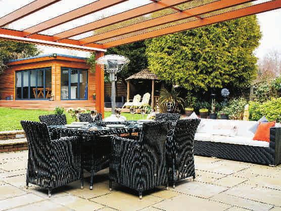
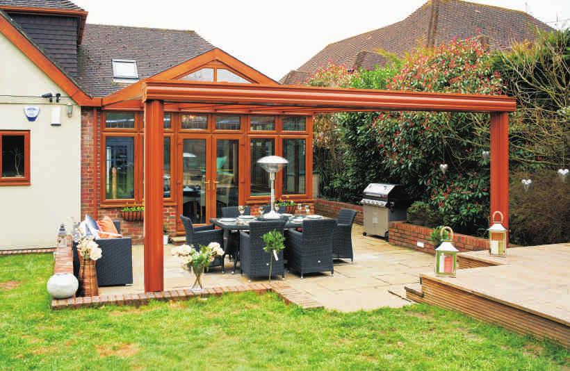
1 Installation Guide Simplicity Alfresco V1.9 Lu070318


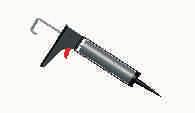


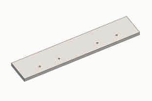
2 Tools Required Below is a list of tools that you will require to install your the Simplicity Alfresco System. Cordless Drill Mastic Gun Spirit Level Tape Measure 13mm Spanner 13mm Socket & Ratchet 10mm Socket & Ratchet 4mm Drill Bit 8.5mm Drill Bit White Rubber Hammer Pozi Head Screwdriver Countersink 8mm Magnetic Mallet & Flathead Nut Driver Roofing Square 45mm Hole Saw Aluminium Chop Saw Tube of Sudaflex Co2 Geni Hoist Digging Equipment Parts Supplied Below is a list of the parts supplied with your new Simplicity Canopy. Please check that all parts are present before starting installation. Roof Glazing Bar 8mm Glass Egde Roof Glazing Bar 8mm Glass Gutter Gutter Cladding Wall Plate Wall Plate End Cap Post Cladding Post Extrusion Post Cladding Downpipe Roof Glazing Bolster Bar Small Cladding Wall Plate Wing 8 Eaves Beam Eaves Beam End Caps Eaves Beam Pitch Adjuster Eaves Bolster Bracket End Bar Bolster Bracket Post Bracket Glass Stop M8 x 20mm Hex Headed Bolt amount = each bolster bar, 2 per end bar, 4 per main bar and 4 per post. Glass Connector 25mm x 5mm Hexagon Headed Screws x2 per main bar for the bar end plates. Light Channel X2 20mm x M6 Stainless Steel Nut & Bolt End cap casting Flat Joining Plates No. 10x 25mm Hexagon Drill Screws x 8 per post and 4 per bar and 4 per end cap casting M8 x 30mm Hex Headed Bolt with Nylock Nuts x1 per bolster bar to fit the bars to the wall plate. No. 10x 25mm Countersunk Screws Countersunk screws to join the eaves beams M8 x 16mm Hex Headed Bolt and Stainless Steel Dome Nuts (amount is every 300mm along the gutter) For example if the gutter is 3000mm long you need for the end = 300mm centers. *Please refer to your CAD drawing for each individual order as this will show the roof bar spacing as per your order. This installation guide is generic and the centre's spacing is given as a guide example only. *Please refer to your CAD drawing for each individual order as this will show the roof bar spacing as per your order. This installation guide is generic and the centre's spacing is given as a guide example only.


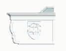
3 Please reference the CAD during installation as this is just a general guide, your CAD will provide you with more specific details for your install. Cross Section CAD Drawing Preliminary Stages and Planning Before starting your install please check all components for quantity and damage. Below is a Roof Span chart which you MUST refer to in order to establish the maximum centre to centre dimensions of your roof bars and posts. SPAN CHART Simplicity Alfresco Up to 6m Projection 800mm Roof Spacing s POST SPACINGS Simplicity Alfresco Up to & Including 6m Projection 6m Post Spacing s PLEASE NOTE A MAXIMUM OF 500MM OVERHANG ON THE GUTTER IS ALLOWED Base & Post Connection Information Post You have two options for fixing the posts to the ground, Option 1 is to bolt down to a pad foundation. Option 2 is to cast the posts into the ground, see illustrations. With both options you need to be mindful of the drainage connection, if you are connecting underground you need to allow for the rainwater fall. Both options need the cleat installing into the bottom of the post to enable the bolt down or to help with wind uplift. L - Brackets inside the post cast in foundation L - Brackets inside the post bolted to foundation 600mm x 600mm x 600mm pad stone depending on a site specific survey 3

4 Be aware! You must ensure all glass is installed with the film facing upwards (sky). This will ensure that if installing self cleaning glass it is the correct way up. Please note when ordering Pilkington Self Cleaning Glass: Pilkington Activ needs both daylight and rain to work effectively. When the roof angle gets too low the rain does not wash the loosened dirt off as effectively. A good flow of water across the glass is beneficial. Pilkington Activ still gives better results than ordinary glass with low angle roof applications. We recommend a minimum angle of 10 degrees, but 30 degrees or more is ideal. You are now ready to start installing the structure, following all steps within this guide. Lighting (if required) The lighting consists of an aluminium extrusion that can fit to either the bottom of the wall plate, or the back of the eaves beam. When installing lighting please consider cable exist and cable entry to the light channel. The lighting also comes with an electrical capacitor for each 6m of light and an optional external grade plastic box to house the capacitors if the installation requires that they be mounted outside. STEP 1 Foundation Hole Positions for Posts When the simplicity Alfresco was ordered a size was confirmed for the height at the front and the back, please reference these measurements because the canopy has been cut to the correct angle. Then establish the height of the structure at the back (wall edge) and the height at the front. The height at the front must be above 2.1m to underside the gutter to meet the minimum legal head height requirement. Once you have established your height at the front and back, deduct the height at the front from the height at the back to give you The Fall (x). Measure distance 'x' up the wall and position your roof glazing bar at this height on the wall. Let the other end touch the ground and where that touches will be the centre of your hole for the foundation. IMPORTANT: Use Roofing Square to ensure the bar used is held square to the wall. 4


.")
5 STEP 2 Digging of Holes for foundations Please refer to the chart below to determine the size of the holes that need to be dug. We recommend a minimum of 600mm x 600mm x 600mm of concrete. Please note the following are for guidance only and will need to be verified by a structural engineer. All Canopies are recommended to have a minimum size of following: 600mm x 600mm x 600mm deep Ensure that when the excavations are complete that the base of the holes is level with each other. STEP 3 Fitting of wallplate to the Wall Attach the wall plate strip to the wall using suitable fixings (not supplied). Recommended spacing for these fixings is 200mm. YOU MUST ENSURE THE WALL PLATE IS NOT TWISTED OR BOWED AS THIS WILL PREVENT THE WALL PLATE WING FROM BEING FITTED. USE A SPIRIT LEVEL TO MAKE SURE THE WALL PLATE IS FITTED LEVEL. 5


6 STEP 4 Preparation of the Wall Plate Wing Measure 35mm in from one end of the Wall plate and mark before you drill. Ensure the 8.5mm hole is in the centre of the bolt channel on the wall plate wing. Once this is done drill an 8.5mm hole. REPEAT THIS PROCESS AT THE OTHER END OF THE WALL PLATE WING You now need to reference your glass WIDTH before you drill any more holes. Your hole centres now need to be spaced 20mm wider than your glass width. Example: If your glass width is 750mm your hole spacing's need to be 770mm. Once you have calculated this measurement MARK you wall plate and ensure they are spaced equally BEFORE drilling. Once you are happy that the spacing's are equal, proceed to drilling using an 8.5mm drill bit. STEP 5 Install the wallplate wing onto the wall plate. Once you have set up your access equipment, drill 2 holes through the glass channel to help retain the wall plate wing on the wall as a suitable position to obtain a fixing, then hook the wall plate wing onto the wall plate and fix into position to prevent it falling while you carry on with the rest of the installation. 6
 50mm from the edge and at around 300mm")


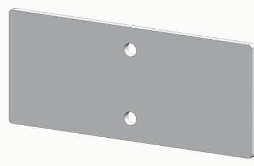
7 STEP 6 Attach the Gutter Section to the eaves beam. Drill the gutter in the centre of the two lines as the below image (fig 3) 50mm from the edge and at around 300mm centres along the whole gutter, slide the relevant amount of m8 x 16mm bolts into the eaves beam with the thread sticking out. Before you connect the two parts make sure you apply a thick bead of sudaflex along the inside of two extrusions just above the bolts to prevent the rainwater running between the two sections. Then marry the two parts together and align the two ends, then tighten as below. Fig 1 Fig 2 STEP 6a Fig 3 Fig 4 If the gutter is longer than 6m, please include step 6a. Ensure all gutter joins are joined over a post position to maximizes the wind and snow loadings on the structure Using the two 300mm long x 59mm x 8mm thick joining plates supplied place the plates into the channels as shown in the below pic to 150mm deep and drill using the countersink drill bit, then screw together using the No 15 x 25mm screws, repeat the process on both sides of the join and make sure you stagger the gutter joins and the front gutter cover to improve the strength. 7


.")
8 STEP 7 Install the gutter castings at both ends of the gutter / eaves beam. To do this you need to run a bead of Soudaflex around the outside ridge of the casting, ensuring that when you place the casting inside of the eaves beam you achieve a good seal, place the casting in to the eaves beam and gutter then drill a 4mm countersunk hole into the back of the eaves beam 80mm down from the top of the eaves beam and 15mm in from the edge and fix into the tab using a No 10 x 25mm countersunk screw. Ensure the casting is level and aligned with the front gutter cover and then secure (using the same countersunk screw as before) the second horizontal tab through the eaves beam pitch adjuster channel in the eaves beam. Lastly secure the front vertical tab using the M6 20mm stainless steel Nut and Bolt. Also before the eaves beam pitch adjuster is installed fix down through the channel into the 3rd tab. Locate top tab here Locate tab inside of gutter Locate back tab inside of eaves Screw posts To seal these, you will need the tube of sudaflex (both supplied). Apply another continuous bead of Soudaflex around the entire inside profile and ensure the 2 screw ports are filled with Soudaflex. Repeat this process at the other end Step 8 Now install the eaves beam pitch adjuster and ensure you slide the correct amount of m8 x 20mm bolts into the eave beams pitch adjuster before you fix the side castings into position. STEP 9 Each Leg has 1 cleat at the top. The cleat has 4 pre drilled holes, if the posts are at the end of the eaves beam measure 32mm from the end of the eaves beam to the start of the cleat as below, this will ensure the clip on cladding does not project out past the end of the casting. Then attach the cleat as shown, ensure they are secured tight using all 4 m 8 bolts. Then attach all other cleats in the positions you want the posts to be. If the structure is longer than 6m and the gutter needs to be joined, ensure the join is over the post and follow the joining procedure 8

9 STEP 10 Fitting of Post Feet to Post Slide the two post feet into the bottom of the post and attached using 2 No 5.5mm x 25mm self drilling screws as below image STEP 11 Cutting the Posts Measure the height of the structure at the front and add to this dimension the depth of post that will be going into the ground. The total of this is the length at which your posts need to be cut to size. STEP 12 Drill the Posts Drill each post using a 4mm pilot drill bit at the position to correspond to the cleat (40mm down and 40mm in from the inside edge of the post), ensure you do not clash the fixing with the cladding that will be fitted at a later stage. Repeat on the opposite side, ensure that the post foot is facing the desired orientation to suit your hole and does not clash with the sides of your foundation. 9


10 STEP 13 Fitting of Post to Gutter Section Slide the post over the fixed cleat on the gutter section and ensure the post is touching the underside of the gutter beam i.e. no gap. If the post is positioned at the end i.e no overhang, then using 4 No 5.5mm x 25mm self-drilling screws fix through the inside of the post into the post cleat. STEP 14 Preparing Glazing Bars for Glazing Slide the edge roof glazing bar into the bolster bar first and then do the same to the other edge bar, then repeat for all bars. Do not fit the glass stops yet. 10


11 Step 15 Stand Post & Gutter Beam Up Before you stand the front of the structure up ensure you add the relevant amount of m8 x 20mm bolts into the channel of the eaves beam pitch adjuster so that you can bolt the main bars down. Using the excavated holes position each of the post into the centre of the hole and stand the whole frame including eave beam and gutter upright then brace as necessary to hold it upright. Depending on the size you may need to brace this with timber or something similar to prevent it falling. STEP 16 Before fixing the first glazing bar please cut the first 110mm of the upstanding flipper gasket from the eaves beam pitch adjuster, now fix the first glazing bar (complete with bolster bar) to the gutter and eaves beam and to the wall plate wing using the m8 x 20mm bolts supplied and nylock nuts. Important! DO NOT OVER TIGHTEN THE BOLTS AT THE WALL PLATE WING END AS THIS WILL DISTORT THE WALL PLATE WING. STEP 17 Repeat step 16 at the other end of the structure so that the frame is solid. Step 18 Using a square against the wall plate wing and the bolster bar, move the front legs either left or right to make sure the structure is square. 11


12 STEP 19 Fitting of The Remaining Glazing Bars Follow step 18 until all bars are installed.cut 160mm of upstanding flipper gasket before you place each glazing bar, this is the amount of material required to enable the front bolster bar bracket to sit flat on the eaves beam pitch adjuster. STEP 20 Sealing Wall Plate wing against the Wall If flashing is required or silicone to seal the wall plate against the wall it needs to be done prior to the glazing panels being fitted. STEP 21 Glass sheets The glass sheets come with a protective film fitted to one side. This needs to be removed prior to fitting. The side with the film is the TOP face, make sure this is the right way up. 12

13 STEP 23 Glazing the Structure with Glass We recommend the use of a co2 geni hoist for the glazing process as it can sit directly under the sheets of glass Depending on the pitch you can glaze the structure with the front gutter cladding already installed, however we recommend fitting this after the roof panels have been installed. Using a soap solution and a 25mm paint brush (not supplied) lubricate the edges of the glass panels Then slide the glass complete with connector into the two bars all the way in to the wall plate wing. Then repeat above process to lubricate the panel and Insert the next section of glass complete with the glass connector installed. Ensure you seal the glass connector before two connectors meet together. Now fit the front glass stop using x2 M6 x 30mm self tapping screws and install the glass plates as you go. Clean the tops of the each glass panel as you go! Continue this process until your structure is fully glazed. STEP 23a Glazing the Structure with Polycarbonate First you will need to notch the ends of the poly sheet capping to allow for the capping to go into each bar, the poly sheet capping fits into the bar from the front and requires a notch to miss the eaves bolster bar, trim this with a thin grinder disk or suitable aluminium saw. Depending on the pitch you can glaze the structure with the front gutter cladding already installed, however we recommend fitting this after the roof panels have been installed. Using a soap solution and a 25mm paint brush (not supplied) lubricate the edges of the poly panels. Then slide the poly complete with f section into the two bars all the way in to the wall plate wing. Then repeat above process to lubricate the panel and Insert the next section of polycarbonate complete with the F section / poly sheet capping already installed. 13


14 Ensure you seal the poly sheet capping around the edges and the top of the sheet before installation. Now fit the front glass stop/front bar caps using x2 M6 x 30mm self-tapping screws and install the glass plates as you go. Clean the tops of the each poly panel as you go! Continue this process until your structure is fully glazed. STEP 24 Fix the gutter cladding onto the top of the gutter and press into position, ensure that the bottom clip is fully home. STEP 25 Make Sure your structure is Square STEP 26 Ensuring the structure is level Bottom Clip To ensure the structure is square, using the roofing square, attach one edge of the square to the wall plate wing and the other edge will need to continuously touch the other edge of the square, this will ensure the gutter beam is perpendicular to the wall plate. Using a spirit level ensure the front beam is completely level and your posts are plumb. 14


15 STEP 27 Concrete the post in or bolt down STEP 28 Clip on the two side claddings for the posts and the rear cladding, leaving the front post downpipe cladding for now. Step 29 Connect your drainage Drill the hole in the gutter 105mm from the inside edge of the gutter as show, make sure it is directly underneath the gutter cover. Then insert the spigot into the end of the outlet and the other end of the spigot into the pipe. Then lay the pipe into the post cladding.then clip the downpipe and the cladding to the post. 15

16 Step 30 Make good around the posts Step 31 Install the trims for the underside of the bolster bars If you are not installing lighting, now install the small cladding on the underside of the bolster bars and the wall plate to hide all bolt heads. If lighting is required see the lighting appendix below. To follow on next update. Step 32 Lighting installation (if required) Inside of the light channel you will find a 12 Volt LED self-adhesive strip light, to access this just unscrew the aluminium end cap and slide out the polycarbonate lenses. You will need to connect the black and red cables to some compatible flex cable that is small enough to run through the trims on the alfresco, or through the wall plate and the main bars. Attaching the lighting to the Alfresco eaves beam: Before you attached the light channel please consider the cable route and ensure you have enough cable to run under the main bar and out of the wall plate to the capacitor. If the hole in the light channel is not already drilled, then you need to drill up through the top of the light channel close to the back so that the cable cannot be seen from the ground using a 6mm brill bit, ensuring the hole is aligned with a main bar so it can be covered with the aluminium trim, then crimp the cables that exit the light channel with the additional cable required for the cable run. Once you have passed the cables through the hole simply snap the light into the channels along the back of the eaves beam or using a rubber mallet tap it into the light channel as below image. If you struggle consider using a large G clamp to help it to snap into place. Then run the cables up the main bar and out of the wall plate at the desired location. Then cover the cables using the aluminium trims supplied. 16


17 Attaching the lighting to the Alfresco wall plate: To do this drill a hole through the back of the light channel (facing the wall) in the desired location for cable exit using a 6mm drill bit, crimp the cables to the red and black LED cables exiting the light channel and feed the extended cables through the hole and run them into the building or the plastic external box supplied and connect them to the capacitor. Then slide the polycarbonate lens back into the light and screw the end cap back on to the light channel. The capacitor will then need to be powered to the mains either via a fused spur or a plug socket as per the specification detailed on the lighting capacitor. End. 17


18
Installation Guide Contemporary Alfresco V1.3 LU
 Installation Guide Contemporary Alfresco V1.3 LU 010818 Tools Required Below is a list of tools that you will require to install you're the Contemporary Alfresco System. Cordless Drill Mastic Gun Spirit
Installation Guide Simplicity 6. v3.5 lu171117
 0845 869 6006 www.canoports.co.uk Installation Guide Simplicity 6 v3.5 lu171117 Tools Required Below is a list of tools that you will require to install the Simplicity 6 Canopy or Carport. Cordless Drill
Installation Guide Simplicity 16. V2.9 Lu171117
 0845 869 6006 www.canoports.co.uk Installation Guide Simplicity 16 V2.9 Lu171117 Tools Required Below is a list of tools that you will require to install the Simplicity 16 Canopy or Carport. Cordless Drill
GROWING BETTER THROUGH DESIGN. 6ft Lean-To LEAN-TO. Assembly Instructions 04/02
 GROWING BETTER THROUGH DESIGN 6ft Lean-To LEAN-TO Assembly Instructions 04/02 6ft Lean-To Greenhouse Base Plan Introduction/Tools/Contents / / Contents This is a copy of our Lean-To greenhouse base plan.
Gardman Lean-to Greenhouse Assembly Instructions
 Page 1 Gardman Lean-to Greenhouse Assembly Instructions Our Help Line provides support and advice to customers of Summer Garden Buildings after ordering. For advice before you buy you can phone us free
This installation guide has been created to assist in constructing a Liniar conservatory roof from a kit format.
 1.00 - Introduction This installation guide has been created to assist in constructing a Liniar conservatory roof from a kit format. Please note, each roof has been individually designed to meet specific
Synseal assembly guide 2009:Synseal assembly guide /2/09 12:38 Page 1. Conservatory Roof Assembly Guide
 Synseal assembly guide 2009:Synseal assembly guide 2007 9/2/09 12:38 Page 1 Conservatory Roof Effective from February 2009 Synseal assembly guide 2009:Synseal assembly guide 2007 9/2/09 12:39 Page 6 3.1
INSTALLATION INSTRUCTIONS
 Tools required for the installation. A. Core Drill 87mm Drill bit B. Tape measure C. Spirit Level D. Marking pen E. Caulking gun F. Cutting Pliers G. Cordless Drill and Philips head bit, 5mm Drill bit.
Greenhouse Assembly Instructions
 Greenhouse Assembly Instructions Our Help Line provides support and advice to customers of Summer Garden Buildings after ordering. For advice before you buy you can phone us free 7 days a week on 0800
INSTALLATION INSTRUCTIONS
 Tools required for the installation. A. Core Drill 87mm Drill bit B. Tape measure C. Spirit Level D. Marking pen E. Caulking gun F. Cutting Pliers G. Cordless Drill and Philips head bit, 5mm Drill bit.
Version 2016_1.1 VICTORIAN ASSEMBLY INSTRUCTIONS. Victorian Vi-23, 34, 36
 Version 2016_1.1 VICTORIAN ASSEMBLY INSTRUCTIONS Victorian Vi-23, 34, 36 PRODUCT INFORMATION Dear customer, Thank you for buying a high-quality aluminium greenhouse. REMARKS The drawings in these instructions
CONSERVATORY ROOF INSTALLATION GUIDE Issue
 CONSERVATORY ROOF INSTALLATION GUIDE Issue 3 CONTENTS 1. Statements 2. General assemblies 3. Victorian / Edwardian roof installation 4. Jack rafter installation 5. P-shaped roof installation 6. Lean-to
Fitting Instructions
 Fitting Instructions = Actions. Red = Notes you must read before continuing. Grey = Only applies to canopies over 4m widths. Overview 1. Tools you will need. 2. What you will need to provide. 3. Description
ENGINEERING STRENGTH INSTAL L AT I O N M A NUAL OUR STRENGTH IS OUR STRENGTH
 ENGINEERING STRENGTH INSTAL L AT I O N M A NUAL OUR STRENGTH IS OUR STRENGTH RAFTER PREPERATION RAFTER PREPARATION A FRAME PREPERATION AND ASSEMBLY A FRAME PREPARATION AND ASSEMBLY... Open boxes, remove
This installation guide has been created to assist in constructing a Liniar conservatory roof from a kit format.
 1.00 - Introduction This installation guide has been created to assist in constructing a Liniar conservatory roof from a kit format. Please note, each roof has been individually designed to meet specific
Eurocell conservatory roof system. Installation manual Issue 3
 Eurocell conservatory roof system Installation manual Contents Statement General Assemblies Cross Sections Victorian/ Edwardian Roof Installation Jack Rafter Installation P Shape Roof Installation 15-45
Document: Installation Overview Guide No: 017a Description: Omega Canopy, Lean-To Style, Post-Supported, Glass-Clear Plate Polycarbonate Roof Panels
 Page 1 of 11 Sections: Section No. Section Description Page No. 01 Essential Tools 2 02 Tools that will make Installation easier 2 03 Items to be supplied by Installer 2 04 main components 3 05 Overview
SLIDING MECHANISM TROLLEY CATCH TROLLEY ASSEMBLY FLOOR GUIDE
 Set A Set B P7001 Standard Kit Glass Door FITTING INSTRUCTIONS SUGGESTED TOOLS DRILL MITRE/CHOP SAW TAPE MEASURE (Image for reference only) HACKSAW POCKER DOOR KIT SHORT / LONG Z SECTION LONG Z SECTION
Safety Glasses Safety Gloves Ladders Measuring Tape Spirit Level String Line. Tin-Snips Rivet Gun Caulking Gun Silicone Socket Set
 BEFORE YOU START Carefully read these instructions and refer to them constantly during each stage of construction. If you do not have all the necessary tools or information, contact Stratco for advice.
OXYGEN INSTALLATION. Revision date
 12345 1 Hardware List 12345 Flat head wood screw #9 x 7/8 long with #2 Phillips drive, silver Used to attach surfaces and end panels Hex set screw ½-13 x 2 long with 1/4 hex drive, black Used on Legs Hex
INSTALLATION GUIDE. Outback. Flat Attached BEFORE YOU START ADDITIONAL MATERIALS TOOLS REQUIRED. VERAnDAHS PATIOS CARPORTS
 INSTALLATION GUIDE Outback VERAnDAHS PATIOS CARPORTS Flat Attached BEFORE YOU START It is important to check your Local Government Authority requirements before the installation of your new Stratco Outback
Installation Instructions
 Installation Instructions Alcove Enclosure Before Installation please check that your shower enclosure system is undamaged Please read these instructions carefully March 2015 TOOLS REQUIRED Electric or
 SUPREME WALL GARDEN ASSEMBLY INSTRUCTIONS 24/08/16 www.hallsgreenhouses.com Please refer to website for the most up to date instructions. SAFETY WARNING 1. Always wear protective glasses, shoes, gloves
OUTBACK FLAT ATTACHED VERANDAH PATIO CARPORT - INSTALLATION GUIDE BEFORE YOU START TOOLS REQUIRED ADDITIONAL MATERIALS
 BEFORE YOU START It is important to check your Local Government Authority requirements before the installation of your new Stratco Outback Flat Verandah. It is the builder s responsibility to ensure any
START HERE BEFORE YOU BEGIN FIG 1 STEP 2
 PROFESSIONAL INSTALL RECOMMENDED REAR MODULAR / MULTI LED ROOF MOUNTS PART#: Z350040 / Z350050 REAR ROOF LED LIGHT MOUNTS Parts included (1) - Driver Side Roof Mount Upright (1) - Passenger Side Roof Mount
Classicroof. Low Pitch Lean-to. Installation Guide SEPT 2015 V3
 Classicroof Low Pitch Lean-to Installation Guide SEPT 2015 V3 PRE-INSTALLATION CHECKS At this stage do not fix the frames down - pin only to the house wall (one fix per side) to allow the conservatory
Dura-Lock Roof System
 DLR-14 Dura-Lock Roof System Assembly and Installation Instructions Read the instructions before starting the job. They explain the steps required to produce a finished product that will meet factory specifications.
ultraframe Classic Low Pitch Lean-to Installation Guide
 ultraframe Classic Low Pitch Lean-to Installation Guide Version 1.0 May 2011 Tools required 8, 10, 13mm Socket Spanner Deadblow Hammer or White Rubber Mallet No. 2 Pozi-drive Bit Hack Saw Drill/Screwdriver
Double Beam Freestanding Pergola Installation Guide
 Double Beam Freestanding Pergola Installation Guide Patent Pending. Copyright 2011 USAVinyl, LLC - All Rights Reserved The information contained in these instructions are proprietary to USAVinyl, LLC and
INTRODUCTION. EqunioxRoof.com. Pro Tip
 INSTALLATION MANUAL INTRODUCTION The Equinox Louvered Roof System is designed to be installed in an aluminum frame. All these sections are 1/8" thick extruded aluminum. All engineering for this system
Installation Guidelines
 Page 1 Tools You ll Need 4 ft. Carpenter s level Chalk line (to mark U channel locations) Cordless drill/nut driver Caulking gun Chop saw with a metal cutting blade on it (required to make accurate and
Piazzola Pergola Awning Manufacturing and installation guide
 Piazzola Pergola Awning Manufacturing and installation guide Date Changes Page General information Maximum and minimum width Width Projection 150 to 349 cm 350 to 500 cm From 200 to 250 cm X From 251 to
Pergola Installation Instructions
 Pergola Installation Instructions TOOLS REQUIRED HAMMER DRILL 1/2 MASONRY BIT PENCIL DRILL 3/16 DRILL BIT LEVEL SQUARE LADDER WRATCHET & SOCKETS RUBBER MALLET 2 TAPE MEASURE Column/Post Placement Table
Installation Guidelines
 Page 1 Tools You ll Need 4 ft. Carpenter s level Chalk line (to mark U channel locations) Cordless drill/nut driver Caulking gun Chop saw with a metal cutting blade on it (required to make accurate and
Installation Guide. Evolve bi-fold. 8. Door restrictor- optional p9. 1. Before you start p2. 9. Adjustment. 2. Measuring and surveying p2
 Evolve bi-fold Installation Guide 1. Before you start p2 8. Door restrictor- optional p9 2. Measuring and surveying p2 3. Configuration details p4 4. Installation p5 5. Glazing p5 6. Glazing packer details
Zero Threshold TM. Hints and Tips Handbook. Birdlip. Burford. Blockley. Bourton
 Birdlip Burford Zero Threshold TM Hints and Tips Handbook Blockley www.edengreenhouses.com Bourton Customer Helpline: +44 (0)1242 676625 Mon Fri 9:00am 5:00pm mail@eden greenhouses.com EH 1.02 Dear Customer,
assembly guide effective from April 2005
 assembly guide effective from April 2005 assembly guide section 1 before you start 3 section 2 typical Georgian roof installation 4 section 3 fitting the traditional gutter 9 section 4 tie bars 10 section
INSTRUCTION GUIDE SANCTUARY CANOPY. C & A SUPPLIES LTD, Bidder Street, London E16 4ST tel: WEB:
 INSTRUCTION GUIDE SANCTUARY CANOPY 1. Add gasket to wall plate 2. Drill holes in wall plate along the two rib lines The first pair of holes should be 25mm from the edge and then spaced every 525mm along
Cardo DOOR & RETURN SHOWER ENCLOSURE INSTALLATION PLEASE READ THESE INSTRUCTIONS CAREFULLY.
 Cardo DOOR & RETURN SHOWER ENCLOSURE INSTALLATION PLEASE READ THESE INSTRUCTIONS CAREFULLY. IT IS RECOMMENDED TO USE A TRAINED SHOWER INSTALLER FOR THIS SHOWER TO OBTAIN THE BEST INSTALLATION. D Square
Document: Installation Guide Guide No: 019 Description: Omega Canopy, Free-Standing, Gable-Roof, Type 1
 Page 1 of 42 Sections: Section No. Section Description Page No. 01 Essential Tools 2 02 Tools that will make Installation easier 2 03 Items to be supplied by Installer 2 04 Canopy main components 3 05
ATLANTIS RAIL Contact Information
 ATLANTIS RAIL Contact Information Customer Service (800) 541-6829 (508) 732-9191 Spectrum System Installation Instructions Atlantis Rail s Spectrum System is an easy to install, universal cable railing
LEGENDS RETRACTABLE DOOR SCREENS
 LEGENDS RETRACTABLE DOOR SCREENS MAGNETIC LATCHING DESIGN SYSTEM 42 I N S T A L L A T I O N I N S T R U C T I O N S 1 MOUNTING OPTIONS Recess : Mount the Screen Cassette using Recess Mounting Clips Recess
E N G L I S H GARDEN SHED. Assembly Instructions. Suitable for Models WITH VARYING DEPTHS
 GARDEN SHED Assembly Instructions Suitable for Models 6' Wide 8' Wide 0' Wide WITH VARYING DEPTHS GI0003 November 0 INSTALLATION ADVICE It's Not That Difficult! The construction of your shed isn't as complicated
SwingSafe Swing-Away Mailbox Support Diagram
 SwingSafe Swing-Away Mailbox Support Diagram Wood Mounting Plates Top Arm (B) Muffler Clamps (A) Carriage Bolts and Nuts Bottom Arm 4-Foot U-Channel Post USPS Recommended 42-44 Height Ground Slope Hex
SLIDING MECHANISM TROLLEY CATCH TROLLEY ASSEMBLY FLOOR GUIDE
 Set A Set B P7001 Standard Kit FITTING INSTRUCTIONS For use with 44mm thick doors only For Single and Double doors IF INSTALLING A TOUCH LATCH, PLEASE READ THE CORRESPONDING FITTING INSTRUCTIONS FIRST
GV Standard Sliding Over Roof Installation Instruction Manual
 GV Standard Sliding Over Roof Installation Instruction Manual Technical experts in the design, manufacture and supply of precision engineered, architectural rooflights for residential and commercial buildings.
YUKON PATIO COVER INSTALLATION INSTRUCTIONS
 YUKON PATIO COVER INSTALLATION INSTRUCTIONS Before You Begin: Consult your local building department for any required permits You may be required to obtain a building permit for this structure. Contact
Clearview Railing System Installation Instructions
 Clearview Railing System Installation Instructions Disclaimer: AGS Stainless, Inc. has its Clearview Railing Systems designed by a professional engineer to meet the requirements of the latest national
DUTCH GABLE FREESTANDING CARPORT
 DUTCH GABLE FREESTANDING CARPORT STRATCO OUTBACK ASSEMBLY INSTRUCTIONS. Your complete guide to building a FREESTANDING Outback DUTCH GABLE CARPORT BEFORE YOU START Carefully read these instructions. If
SIMPLER BETTER FASTER
 SIMPLER BETTER FASTER 1. FITTING RING BEAMS DETAILS Always work anti-clockwise viewed from outside the roof. Each bar should be sequentially numbered, i.e. 1, 2, 3. Select the ring beam, position the left
IMPORTANT!!! ASSEMBLY ASSEMBLY INSTRUCTIONS. (Internal Dimensions)
") ASSEMBLY ASSEMBLY INSTRUCTIONS (Internal Dimensions) Ent Spec Edition Ltr v-0- Overall dimensions including base: 7. L x 9 W x 0 H cms 97.5" L x 7" W x 8.7" H IMPORTANT!!! Please read these instructions
ASSEMBLY ASSEMBLY INSTRUCTIONS (Internal Dimensions) Ent Spec Edition Ltr v-0- Overall dimensions including base: 7. L x 9 W x 0 H cms 97.5" L x 7" W x 8.7" H IMPORTANT!!! Please read these instructions
INSTALLATION GUIDE SLIMLINE ROOF LANTERN 4 PANE CONFIGURATION
 INSTALLATION GUIDE SLIMLINE ROOF LANTERN 4 PANE CONFIGURATION SLIMLINE STEP-BY-STEP INSTALLATION GUIDE Thank you for choosing Roof Maker, we hope you are delighted with your new rooflight. Our roof lanterns
compile system INSTALLATION GUIDE Updated January 2019
 INSTALLATION GUIDE Updated January 09 compile system Table of Contents Panels 0 Quick Connect Clips 0 Lock Clips 0 Panel Trims 0 Privacy Glass 0 Post Base Covers 04 Electrical 04 Power Distribution Harness
Assembly Instructions
 Unite Panel System Hinge Door July 2016 #12 x / slotted hex washer head bolt Figure 1 threshold bracket frame Detail F threshold bracket threshold bracket (installed) #12 x / slotted hex washer head bolt
utopia Window & Door Products Orangery Home Extension Products Conservatory Products Skylight Products
 Window & Door Products Orangery Home Extension Products Conservatory Products Skylight Products utopia Installation Guide Version 1.1 June 2011 Dear Customer, Thank you for choosing the Ultraframe Utopia
Guardian warm roof conversion system. Installation Guide
 Guardian warm roof conversion system Installation Guide 2 www.guardianroof.co.uk Conservatory walls consist largely of glazed elements including windows and doors that may include structural mullions or
Locker Pedestal Installation Instructions
 Locker Pedestal Installation Instructions LK-PED-INST-0314r1 Parts List Single Pedestal Back to Back Pedestal Horizontal Support Tube TS-169 Post Flange TS-190 Post Cap Fasteners Provided: #8 x ¾ round
INSTRUCTION BOOKLET #C20
 INSTRUCTION BOOKLET #C0 WARNING! ALL MURPHY/WALLBED SYSTEMS CONTAIN STORED ENERGY. FAILURE TO USE AND FOLLOW THESE INSTRUCTIONS DURING THE INSTALLATION PROCESS COULD RESULT IN SEVERE PERSONAL INJURY TO
Installation Guide. Bi-fold Doors
 Installation Guide Bi-fold Doors Installation Guide Components box 1. 6. 2. 3. 7. 5. 4. 8. Contents 1. Fixing plugs 2. Wedge gasket 3. Bottom trolley 4. Top trolley 5. Magnetic keep (x 2 if door height
SLIDING MECHANISM TROLLEY CATCH TROLLEY ASSEMBLY FLOOR GUIDE
 Set A Set B PFD30 Fire Door Kit FITTING INSTRUCTIONS For use with 44mm thick doors only For Single and Double doors IF INSTALLING A TOUCH LATCH, PLEASE READ THE CORRESPONDING FITTING INSTRUCTIONS FIRST
FACTORY STRETCH INSTALLATION INSTRUCTIONS
 !! Important!! Make sure all power is disconnected prior to installation. Wiring to be done according to Local and National Electric Codes by a qualified electrician. Make sure the building and/or structure
GROWING BETTER THROUGH DESIGN LEAN-TO. Lean-To. Assembly Instructions 04/02
 GROWING BETTER THROUGH DESIGN Lean-To LEAN-TO Assembly Instructions 04/02 2 Lean-To Greenhouse Base Plan Introduction / Tools / Contents This is a copy of our Lean-To greenhouse base plan. Dimensions shown
Section 1 Specifications..
 Section 1 Specifications.. Conservatory roofs, Atrium glazing, Rooflight & Entrance canopies E-mail: sales@amartsystems.com 07/06/2006 Section 1 Skycrest - 1 Information sheet product GENERAL. All styles
TABLE OF CONTENTS REQUIRED TOOLS
 TABLE OF CONTENTS SECTION SECTION TITLE PAGE NO. 1 2 3 4 5 Assembling Mounting Structure Installing Bicycle Supports Mounting Rack to Wall Adding Sections Customizing Rack Configuration REQUIRED TOOLS
INS A KSR INSTALLATION INSTRUCTIONS STANDARD PROCEDURE. 1. Verify Curb Installation Required Installation Tools...
 INS-88.300-0A KSR INSTALLATION INSTRUCTIONS STANDARD PROCEDURE 1. Verify Curb Installation... 2 2. Required Installation Tools... 2 3. Unpacking the KSR... 3 4. Attach KSR Bottom Rail to Curb... 5 5. Attach
SLIDING MECHANISM TROLLEY CATCH TROLLEY ASSEMBLY FLOOR GUIDE
 Set A Set B PFD30 SG Fire Door Kit FITTING INSTRUCTIONS For use with 44mm thick doors only For Single and Double doors SUGGESTED TOOLS DRILL G-CLAMP TAPE MEASURE (Image for reference only) HACKSAW POCKET
GlideRite Retractable Cover System For HotSpring & Tiger River Spas (except Classic & pre-2000 Landmark Spas)
") List of Contents Quantity Description 12 #10 x 1 ½ Flat Head Phillips Screw (see pg. 2) 2 #10 x ½ Pan Head Phillips Screw (see pg. 2) 8 ¼ x 2 ½ Lag Bolt (see pg. 2) 7 ¼ 20 x 5 / 8 Hex Head Bolt (see pg.
List of Contents Quantity Description 12 #10 x 1 ½ Flat Head Phillips Screw (see pg. 2) 2 #10 x ½ Pan Head Phillips Screw (see pg. 2) 8 ¼ x 2 ½ Lag Bolt (see pg. 2) 7 ¼ 20 x 5 / 8 Hex Head Bolt (see pg.
Figure A. Figure B. Figure C. Figure D
 Xsite 1 Power/Data Tile and Components Tools Required Tape Measure Cordless Drill/Driver #2 Phillips Screw driver bit Rubber Mallet Flat Blade Screwdriver Figure A Hardware Required Provided as shown Installation
ClearVue Roofing System Technical Manual
 Technical Manual Components CLEARVUE RAFTER BRACKETS CV-02 2 Components CLEARVUE EXTRUSIONS CV-03 3 Components END PLATES - 6mm SHEET CV-04 4 Components END PLATES - 8mm SHEET CV-05 5 Components MECHANICAL
*** All chrome surfaces should be cleaned using a clean damp cloth. *** No abrasive cleaning agents or materials should be used.
 Cleaning *** All chrome surfaces should be cleaned using a clean damp cloth. *** No abrasive cleaning agents or materials should be used. *** No chemical cleaners can be used on the glass use only mild
Series 1500 Aluminum Door Canopy
 Series 500 Aluminum Door Canopy with Sidewings It is our recommendation that you read instructions carefully prior to assembly and installation. Series 500 with Sidewings mounting bar (A) top trim (B)
Skypod. Pitched PVC-U skylights. Installation guide PITCHED PVC-U SKYLIGHTS ISSUE 1
 Skypod Pitched PVC-U skylights PITCHED PVC-U SKYLIGHTS Installation guide ISSUE 1 Skypod pitched PVC-U skylights Installation guide Contents 1. Surveying 3 2. Installation 4 3. Additional information 10
10 x 10 Flat Top Two Tone Pergola
 0 x 0 Flat Top Two Tone Pergola Models: Bordeaux ASSEMBLY GUIDE OPTIONAL ACCESSORIES Arch Kit System ( Arches) Privacy Fence Panel System ( Panels & Middle Post) Bolt Down Bracket Kit ( for Pergola) Ver.0-00
10x10 Trellis Pergola
 0x0 Trellis Pergola ASSEMBLY GUIDE Ver.0-7 Table of Contents PAGE Introduction & Overview...................................................... Pergola Materials Overview..............................................................
VINYL CLASSIC FREESTANDING PERGOLA ASSEMBLY INSTRUCTIONS
 P a g e 1 VINYL CLASSIC FREESTANDING PERGOLA ASSEMBLY INSTRUCTIONS Shown: 8' x 12' Vinyl Classic Pergola with 12" Top and Main Runner Spacing The design of this pergola is based on all posts being installed
LEGENDS RETRACTABLE DOOR SCREENS
 I N S T A L L A T I O N I N S T R U C T I O N S 1 MOUNTING OPTIONS Recess : Mount the Screen Cassette using Recess Mounting Clips Recess within the door jamb area. Recess installations are the most typically
INSTRUCTION BOOKLET #C21. For Wallbed models: KING SIZE
 For Wallbed models: KING SIZE INSTRUCTION BOOKLET #C1 WARNING! ALL MURPHY/WALLBED SYSTEMS CONTAIN STORED ENERGY. FAILURE TO USE AND FOLLOW THESE INSTRUCTIONS DURING THE INSTALLATION PROCESS COULD RESULT
Connect Transit Shelter
 Tools Required *denotes special tools required Connect Shelter, 8ft Connect Shelter, 12ft *Soft, non abrasive protective surface such as a furniture blanket *Source of compressed air (for thorough dust
TRADITIONAL GABLE ATTACHED PATIO AND CARPORT. Your complete guide to building an ATTACHED Outback TRADITIONAL GABLE PATIO or CARPORT
 TRADITIONAL GABLE ATTACHED PATIO AND CARPORT STRATCO OUTBACK ASSEMBLY INSTRUCTIONS. Your complete guide to building an ATTACHED Outback TRADITIONAL GABLE PATIO or CARPORT BEFORE YOU START Carefully read
Installation Instructions
 Supafold Slide Aside System Three Fold Room Divider Installation Instructions Distinctive Doors Ltd Supafold Slide Aside Internal Folding System IMPORTANT: Before proceeding with the installation, and
INSTRUCTION BOOKLET #34. For Wallbed models: KING SIZE SIERRA WITH STORAGE HEADBOARD
 For Wallbed models: KING SIZE SIERRA WITH STORAGE HEADBOARD INSTRUCTION BOOKLET #34 WARNING! ALL MURPHY/WALLBED SYSTEMS CONTAIN STORED ENERGY. FAILURE TO USE AND FOLLOW THESE INSTRUCTIONS DURING THE INSTALLATION
Allora ALCOVE ENCLOSURE INSTALLATION BEFORE INSTALLATION CHECK THAT YOUR ALLORA SHOWER ENCLOSURE SYSTEM IS UNDAMAGED
 Allora ALCOVE ENCLOSURE INSTALLATION BEFORE INSTALLATION CHECK THAT YOUR ALLORA SHOWER ENCLOSURE SYSTEM IS UNDAMAGED ALCOVE SHOWER Your shower can be installed to open Left hand or Right hand by rotating
Ensure there is reasonable access for materials and working space, ensure the shed site is level and consider the disposal of run-off water.
 INSTALLATION GUIDE TM Flat Roof Homesheds THE POTTER BEFORE YOU START It is important to check your Local Government Authority requirements before the installation of your new Stratco Potter Flat Roof
XL JOINERY LTD LA PORTE VISTA MODULAR 3 ASSEMBLY INSTRUCTIONS
 XL JOINERY LTD LA PORTE VISTA MODULAR 3 2090mm High x 4687mm Wide ASSEMBLY INSTRUCTIONS READ AND UNDERSTAND THESE INSTRUCTIONS FULLY PRIOR TO STARTING INSTALLATION. IT IS STRONGLY RECOMMENDED THAT A COMPETENT
Assembly Instructions Nevins Phone Booth
 Assembly Instructions Nevins Phone Booth Included Hardware Tools Required supplied by installer Drill & Bit Bolt A - (16) 1/4-20 x 1-1/2 hex head Bolt B - (20) 1/4-20 x 2-1/2 phillips head Screw 1 - (24)
16ft Polytunnel Assembly Instructions
 CONTENTS Section Page 1. FOUNDATION TUBES: Option A Ground Anchor Plates 3 2. FOUNDATION TUBES: Option B Concreted Foundation Tubes 5 3. STEEL FRAME ASSEMBLY & INSTALLATION 6 4. CROP BARS 8 5. TIMBER END
skypod INSTALLATION GUIDE Issue 2 CONTENTS 1. Preparing to install 3 2. Installation 4 3. Installing jack rafters Installation examples 11
 skypod INSTALLATION GUIDE Issue 2 CONTENTS 1. Preparing to install 3 2. Installation 4 3. Installing jack rafters 10 4. Installation examples 11 INSTALLATION GUIDE SURVEYING WARNING 1.2 Good surveying
STRATCO GABLE HOMESHED STRATCO GABLE HOMESHEDS STUBBIE INSTALLATION GUIDE
 STRATCO GABLE HOMESHED STRATCO GABLE HOMESHEDS STUBBIE INSTALLATION GUIDE INSTALL GUIDE BEFORE YOU START COUNCIL APPROVAL It is important that you have local council approval before building your Stratco
Stratco Sanctuary INSTALLATION BEFORE YOU START TOOLS REQUIRED GUIDE
 INSTALLATION GUIDE Stratco Sanctuary Verandahs, Patios and Carports BEFORE YOU START It is important to check with your Local Government Authority prior to the installation of your new Stratco Sanctuary
NEW skypod INSTALLATION GUIDE
 NEW skypod INSTALLATION GUIDE NOW INCLUDES ACUTE CONTENTS 1. Preparing to install 2 2. Installation 4 3. Installing jack rafters 10 4. Installation examples 11 If in doubt at any stage Please contact the
Pergola. Installation Guide
 Pergola Installation Guide Version 1 March 2014 INTRODUCTION Dear Customer Thank you for choosing a Pergola. Please take a few minutes prior to installation to familiarise yourself with this guide. For
PRODUCT INFORMATION MANUAL SECTION: 16 FIXED METAL AWNINGS FIXED METAL AWNINGS
 FIXED METAL AWNINGS Fixed Metal Awnings BAHAMA Maximum Width Minimum Width Minimum projection Minimum Drop TS - Truss Support Maximum Overhang Minimum Overhang Unlimited 500mm TS=1601mm PS=2847mm PS=
Transit Connect Full/Half Installation Instructions
 GATHER THESE TOOLS FOR ASSEMBLY & INSTALLATION 7/16 wrench, T45 Torx socket, 7/16 socket, 3/8 drive ratchet - 3/8 socket One 1/8 square end driver bit provided - Electric drill/driver/18v cordless One
Shed Assembly Instructions
 Shed Kit Contents The shed kit includes all the parts needed to assemble your shed except for tools and fasteners such as screws and nails. The various pieces are pre-cut and many are marked to indicate
ASS 70 FD folding / sliding door. Installation Guide
 ASS 70 FD folding / sliding door Installation Guide IMPORTANT! These doors should be fitted by competent and trained installers. Please read these instructions thoroughly before beginning the installation.
Platinum Swing Panel Installation Instructions
 Platinum Swing Panel Installation Instructions The Standard Platinum Swing Panel is designed to fit baths with a perimeter lip no taller than 20mm. If installing onto baths without a perimeter lip an optional
Curium 19H Installation Instructions & Parts List
 Curium 19H Installation Instructions & Parts List Illustration Curium 19H Right Hand Page 1 of 15 01/07/2016 Revision 2.1 IMPORTANT This shower screen / enclosure must be installed by suitably qualified
ALLORA SWING PANEL INSTALLATION INSTRUCTIONS
 ALLORA SWING PANEL INSTALLATION INSTRUCTIONS Before Installation Please check that your Allora Swing Panel is undamaged SEQUENCE OF INSTALLATION These instructions are also available from the Athena website:
skypod INSTALLATION GUIDE CONTENTS Issue 2 If in doubt at any stage NOW INCLUDES ACUTE BE SAFE WHEN WORKING AT HEIGHT
 skypod INSTALLATION GUIDE Issue 2 NOW INCLUDES ACUTE CONTENTS 1. Preparing to install 2 2. Installation 4 3. Installing jack rafters 10 4. Installation examples 11 BE SAFE WHEN WORKING AT HEIGHT Ensure
Titan Series Awning Assembly and Installation Instructions
 Titan Series Awning Assembly and Installation Instructions Be sure to use safety glasses when assembling and installing the awning. Some metal parts may have sharp edges. Use work gloves to handle them.