PANEL CRIB PIERS AND TOWERS
|
|
|
- Neil Burns
- 5 years ago
- Views:
Transcription
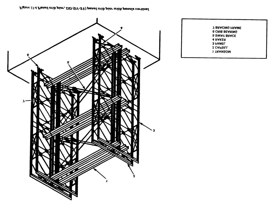
1 CHAPTER 17 PANEL CRIB PIERS AND TOWERS Panel crib piers are made of trusses with panels set horizontally or vertically and are normally braced with transoms, sway bracing, rakers, bracing frames, and tie plates in a panel bridge. Panel crib piers assembled from parts of the Bailey bridge set can be used as Intermediate supports for through- and deck-type fixed bridges. The piers can be set on timber grillage, piles (Figure 17-1), masonry footings (Figure 17-2), or partially demolished piers. Piers in barge bridges. Intermediate landing-bay piers in floating panel bridges with double landing bays. Expedient towers for suspension bridges, lift bridges, gantries, and floating-bridge anchor-cable systems. Expedient marine piers. CHARACTERISTICS OF CRIBS Types of panel crib piers have their own distinguishing characteristics. Panel crib piers are described by the number of trusses (single, double, triple, and so on, as in a panel bridge); the number of stories (number of panels along the vertical axis in one bay, as in the panel bridge); the number of bays (number of panels along the horizontal axis 210 in a given story); and the position of panels in each story (horizontal or vertical). Table 17-1 (page 212) lists the abbreviations used to describe typical panel crib piers. Panel cribs have from one to four trusses on each side, depending on the desired capacity. There must always be at least as many trusses in the crib as in the bridge it supports. Panels in a panel crib pier are horizontal (Figure 17-3, page 212) or vertical (Figure 17-4, page 213). Horizontal panels provide a 5- foot 1-inch (.16 meter) increment in pier height. They are, however, weak laterally and are used one above the other when expedient bracing is added. When ultimate capacity piers are used, any horizontal stories are weaker than vertical ones. Vertical panels provide 10-foot (3.1 meters) increments in pier height. They can be used one above the other in piers up to 70 feet (21.5 meters) high supporting continuous spans and up to 110 feet (33.8 meters) supporting broken spans. In high piers, exceeding three vertical stories,

 piers, bridges. vertical stories are used with only one 5-foot (1.5 meters) horizontal story placed at the top A rocker at top of the crib can be built of of the crib.")

2 are described and illustrated in Chapter 16. the pier base must be doubled for at least half its height or the lower story must be imbedded in concrete for ¾ of its height. Deflection of a span under load tends to change the slope of the bridge at the piers. To prevent large stresses in the bridge and pier, allow some rocking movement at intermediate supports of continuous To assemble 15-, 25-, 35-, 45-, 55-, and 65-foot (4.6, 9.1, 10.8, 13.8, 16.9, and 20 meters) piers, bridges. vertical stories are used with only one 5-foot (1.5 meters) horizontal story placed at the top A rocker at top of the crib can be built of of the crib. TYPES OF BRIDGE SEATING Seating for a continuous bridge is different than that for a broken-span bridge. Continuous-bridge seating includes the following features: crib bearings on standard bearings, inverted junction-link bearings on junction links, or one or two I-beams at right angles to the bridge axis. With this type of bridge seating, bottom chords of the bridge over the seating are normally reinforced by a steel beam to distribute the load and prevent failure of the panel chords due to local bending. These rockers If the crib is fastened rigidly to the bridge, it must rock with the bridge as the girders deflect under load. A rocker at the base of the crib can be built of crib bearings on standard bearings or inverted junctionlink bearings on junction links. This type of pier construction may prove useful on piers less than 10 feet (3.1 meters) wide along the axis of the bridge. It must be built from the bridge downward and the bridge must be capable of holding itself, the pier, and the work crews while resting on rollers for both span lengths until the pier is in position. Heavy bearing plates are needed beneath the crib-bearing so that the entire bridge-pier reaction may be distributed to the pier base. As an expedient when rocker bearings cannot be improvised, seat bridge on timber on top of the piers. Broken-span bridge seating includes the following features: In broken-span assembly, the adjacent ends of the two spans are seated on the junction-link bearings by use of span junction posts and junction links (Figure 17-5, page 214). As an expedient, the adjacent ends of the two spans can be pinned to the vertical panels in the pier, or the two ends can rest on separate bearings. 211
3 212
4 213
5 214

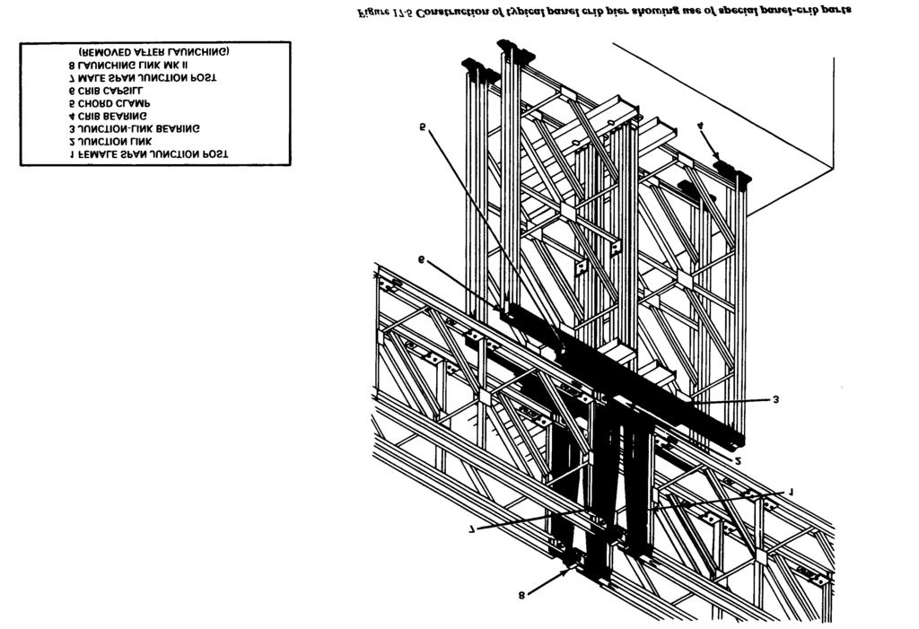
6 SPECIAL PARTS FOR PANEL CRIB PIERS The bridge conversion set No. 3, Bailey type, panel crib pier, contains parts that are used with equipment from the basic bridge set to build panel crib piers. The major items in the conversion set are listed in Table SPAN JUNCTION POSTS Span junction posts are special end posts for connecting adjacent ends of two spans and supporting them on the same bearing. There are two types of span junction posts, male and female, which have lugs that are pinned to female and male ends, respectively, of standard panels. At the junction, each post has two other connecting lugs, a male and female lug at the top according to type, and a universal jaw at the base. Irrespective of type, two posts can be connected at the base by a normal panel pin. Always use a bridge pin retainer on the panel pin at this joint. An intermediate pin hole and recess in the base of each post is for the junction link. During launching, connect the top lugs of the posts by a launching-nose link Mk II. The link will fit only between one female span junction post and one male span junction post, so take care when constructing the two spans to keep all the male lugs on the panels faced the same way. After the bridge is jacked down and posts are pinned to the junction link, remove the link; leave in the pin joining the two posts at their base. Then the gap between the two lugs of the posts allows an upward slope of 1 to 6.7 or a downward slope of 1 to 5 in one span when the other is level. The female span junction post weighs 202 pounds (91.8 kilos) and the male span junction post weighs 194 pounds (88.2 kilos). M2 JUNCTION CHESS Junction chess (Figure 17-6) span the gap in the bridge deck between the ends of the two spans connected by span junction posts. Four junction chess are used at each span junction. The junction chess consists of two 6-foot 10 ½- inch (2.1 meters) timbers fastened to nine steel I-beams 11½ inches (29.3 centimeters) long. The junction chess weighs 149 pounds (67.7 kilos). JUNCTION LINK The junction link (Figure 17-7 page 216) transfers the end reaction from two-span junction posts to a junction-link bearing. Its use limits truss reaction to 25 tons (
7 The junction link is a triangular-shaped steel assembly with two projecting male lugs on its top side spaced to pin with panel pins to the two-span junction posts. Both holes are elongated to permit some play in the joint. A bridge pin retainer must always be used on the panel pins at this joint. The bottom of the junction link tapers down to a nose with a tubular bearing which seats in the curved bearing plate of the junction-link bearing. The junction link weighs 36 pounds (16.4 kilos). JUNCTION-LINK BEARING The junction-link bearing (Figure 17-8) is used under the junction link which supports the ends of the bridge. It can be used in the following ways: 216 When supported by a vertical panel, if male lugs of panel are uppermost, pin jaws of the junction-link bearings to the panel lugs. If female lugs are uppermost, rest jaws of junction-link bearing on top of lugs and fasten them by chord clamps. When supported by a crib capsill (Figure 17-5), secure it to the capsill with chord clamps. When supported by a crib bearing, pin bearing to two center holes of junctionlink bearing with panel pins. When used under female end of vertical panel, rest female lugs of panel on jaws of junction-link bearing and secure them by chord clamps. When supported by timber, lay junctionlink bearing directly on a timber support. The junction-link bearing is made of two 8- inch (20.4 centimeters) channels welded back to back with the same spacing as between channels in the chords of the panel. It is 5 feet 1 inch (1.6 meters) long and has female jaws at each end. The distance between panel-pin holes in the female jaws is 4 feet 9 inches (1.5 meters), the same as vertical distance between pin holes in the pane). Between the webs of the channels in the center of the junction-link bearing is a curved bearing plate on which the junction link bears. There is a hole through the webs of the channels just above the curved bearing plate for a captive pin which locks the junction link in place. There are two panel-pin holes in the webs of the channels beneath the curved bearing plate. They are used to pin the crib bearing which fits in the recess between the channels. A junction-link bearing weighs 217 pounds (99.3 kilos). Its maximum capacity is 25 tons (22.8 metric tons) (Table A-14, Appendix A). CHORD CLAMP The chord clamp (Figure 17-9) is used to pin Crib capsill to panel chord (Figure 17-10). Chord clamps are pinned to any of the holes in the capsill. Crib capsill to female jaw of panel. Crib capsill to junction-link bearing (Figure 17-5). Junction-link bearing to female jaw of panel. The chord clamp is in effect a double-length male lug with two panel-pin holes and a T- head. Slip the clamp between chord channels of a panel until the head bears on the channel flanges; then pin the clamp to a crib capsill or other female joint with a panel pin. If the
8 chord clamp is slipped through two adjacent female jaws, pin it to each by panel pins through both holes in the chord clamp. The chord clamp weighs 11 pounds (5 kilos). 217
9 CRIB CAPSILL The crib capsill (Figure 17-11) distributes the load from the bridge to the main chords of vertical panels or to the three verticals of horizontal panels in a crib. It has unreinforced holes used to take the vertical load. Before panel pins can be inserted in reinforced holes, the holes must be reamed or filed slightly. The reinforced holes are used to pin the capsill to the following: Male lugs of single vertical panels. Male lugs of two adjacent vertical panels. Crib bearing (Figure 17-12). The crib capsill is made of two 4-inch (10.2 centimeters) channels welded back to back to spacer lugs with the same spacing between channels as in the chord of the standard panel. It is 10 feet 2 inches (3.1 meters) long, and has female jaws at each end. Holes are spaced along the webs of the channels. Six pairs of panel-pin holes are reinforced with steel blocks and spaced so male lugs of two adjacent panels or of a single panel can be connected to the crib capsill with panel pins. Additional unreinforced holes for chord clamps are spaced generally at 6-inch (15.3 centimeters) centers between reinforced holes. Before panel pins can be inserted through the holes they must be reamed or filed slightly. The crib capsill weighs 251 pounds (114.1 kilos). CRIB BEARING The crib bearing (Figure 17-13) is used as a base of panel cribs and can be pinned with panel pins to the following: One female jaw of vertical panel (Figure 17-14). Two female jaws of adjacent vertical panels (Figure 17-14). Two central holes of a crib capsill (Figure 17-12). Two central holes of a junction-link bearing. 218
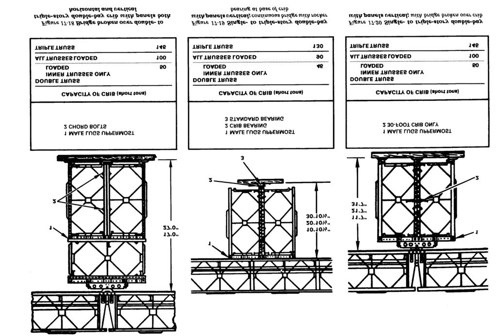
10 load transmitted to the crib by the ends of two independent spans. Continuous-span assembly over the pier transmits greater load to the pier. These reactions are listed in Table The crib bearing can be spiked to a timber sill (Figure 17-14) to provide a rigid base or set on a standard bearing (Figure 17-15) to provide a rocker bearing. The bearing area of the pin is inches by 3 inches, or square inches (36.4 square centimeters). The crib bearing is in effect a double-length male lug welded horizontally to a base block. One of the pin holes is elongated to make pinning easier when both holes are used. If only one hole is needed, the circular one is used. Holes are provided in the base block of the crib bearing for spiking to a timber sill. The underside of the base block has a semicircular bearing to seat on a standard bearing. The crib bearing weighs 37 pounds (16.8 kilos). CRIB LOAD AND CAPACITY The amount of load on and the capacity of a crib must be determined. Chapter 16 describes a method for determining the approximate Figures and (pages 220 and 222) show standard assembly of piers built with special panel-crib parts. Capacities are given in all cases. Single-truss cribs can take 50 percent of the loads given for double-truss cribs with only the inner truss loaded. Use single-truss cribs only for light loads on low cribs. The capacity of panel crib piers is usually limited by the strength of the junction link, junction-link bearing, and crib capsill (Table A-14, Appendix A). If special panel-crib parts are not used, the load is carried by the top members of vertical panels in the crib. Lay timber on top members of each panel to concentrate load at three points: at the center, and near each end adjacent to the panel chords. With the load applied in this manner, the top member of one vertical panel will carry about 14 tons (12.7 metric tons), and piers with this type of bearing will have the same capacity as piers of corresponding assembly built with special parts (Table 17-3, page 222). Table A-14, Appendix A gives the strength of the individual panel-crib parts for use in estimating the capacity of expedient panel cribs. 219
11 220
12 221

13 BILLS OF MATERIAL Table A-15, Appendix A lists the number of parts required to build the standard crib piers illustrated in Figures through 17-21, and the number of unit truck loads required to supply these parts. Panel-bridge conversion set No. 3, panel crib pier, supplies the special panel-crib parts to build a 31-foot 7- inch triple-triple pier with the addition of standard panel-bridge parts. The parts in conversion set No. 3 are listed in Table A-4, Appendix A. The conversion set No. 3 makes two crib-pier loads, each carried by a 5-ton dump truck. These truck loads are described in Chapter 2. The number of crib-pier loads and standard unit truck loads required to build each pier are given in Table A-15, Appendix A. When using this table, note the following Plain bearings and base plates are not supplied in loads needed to build a pier. (Use extras from bridge construction.) Launching links Mk II are used for launching only. Remove them after bridge is in place. Panel pins listed do not include pins for launching links Mk II. STANDARD ASSEMBLY OF TRUSSES AND BRACES The trusses in standard panel crib piers are parallel to trusses in the bridge. The crib must have at least the same number of trusses as the bridge it is to carry. More 222
.")
14 trusses can be added for increased strength (Figures through 17-21). Single-truss assembly can be used only for low cribs carrying light loads. The number of bays in the pier will normally be enough to make the length of the base one third or more as much as the height of the pier (Figure 17-21). All possible bracing frames and tie plates tie trusses together at each side of the crib. In a quadruple-truss pier, bracing frames and tie plates overlap. Brace the entire crib by transoms and sway bracing (Figure 17-22). In cribs with vertical panels, space transoms at 10-feet (3.1 meters) intervals in piers up to 30 feet (9.2 meters). In cribs only one bay long, invert panels of inner trusses with respect to panels in outer trusses so transoms can be attached to both chords. Sway bracing is on the same side of the crib throughout its height. In cribs with two bays of vertical panels, place panels so transoms and sway bracing are either at the center of the crib or at its sides. In cribs with four bays of vertical panels, add extra sway bracing in the outer bays (Figure 17-21). In cribs with horizontal panels, half the panels may be right side up, and the other half inverted so transoms are at both top and bottom. Vertical-plane cross bracing may be provided by sway braces pinned to the swaybrace slot of the inverted second truss and fastened to the transom at the other end, or the sway bracing may be used as described later in this chapter. In cribs under two-lane panel bridges, stagger transoms at the center panels (Figure 17-23). When panels are vertical, transoms in one half under one lane are all on top of panel verticals; in the other half, under panel verticals. At the top and bottom of the crib, transoms can be placed only on the side of panel verticals. Therefore, angles must be welded to the panel chords to take the place of alternate transoms (Figure 17-23, page 224). When the panels are horizontal, angles are also used to replace alternate transoms. Guy high piers to provide greater lateral stability. BRIDGE SEATING If the bridge is broken over the pier so the two spans act independently, use span junction posts, junction links, and junction-link bearings to seat it (Figure 17-5). If the crib is pivoted at its base so the bridge is fastened directly to the crib, slip chord clamps between the channels of the bridge chord and pin them to the crib capsill (Figure 17-16). Figure illustrates rocker bearings using panel-crib parts. This type of rocker bearing rests on abase plate on top of the pier. A wide platform on the top of the pier, to allow some leeway in positioning the baseplates, may be built from transoms and ramps welded in place (as described in the following paragraphs). An expedient rocker bearing may be made from one or two tranverse beams set on the top of the pier. The bearing must be under a panel vertical or the junction of panel diagonals. Figure illustrates another expedient bearing. CRIB BASE There are several ways of setting panels onto a crib. With a fixed base, if panels in the first story of the pier are horizontal they may be set directly on a timber or masonry pier foundation (Figure 17-17). If panels in the first story are vertical, pin the female jaws of the panels to crib bearings which are set on timber or steel footings (Figure 17-20). 223
.")
, or by chord clamps to inverted junction-link bearing (Figure")

15 With a rocker base, the rocker may consist of a crib bearing seated on a standard bearing (Figures and 17-16) or an inverted junction-link bearing set on an inverted junction link (Figure 17-16). The procedure is as follows: If panels in lower story of pier are horizontal, fasten crib capsill by chord clamps to bottom chord. Then pin this crib capsill directly to crib bearing (Figure 17-16), or by chord clamps to inverted junction-link bearing (Figure 17-16). If there is one bay of vertical panels with female ends down in the pier, connect female jaws by chord clamps to top of a junction-link bearing pinned to a crib bearing. If there are two bays of vertical panels, pin the two adjacent center female jaws to a crib bearing which is on a standard bearing (Figure 17-19). 224
16 EXPEDIENT ASSEMBLY (STANDARD TRUSSES) If no special panel-crib parts are available, the following expedient parts can be improvised for standard truss arrangement: Panel chords or any pair of 4-inch (10.2 centimeters) or larger channels with holes drilled at the desired spacing can be used for improvised crib capsills. Angles or lugs with pin holes in their upright parts can be fastened to the crib foundation and panels pinned to them. Another expedient is to have panel pins in female jaws of vertical panel bear on top of an I-beam or rail (Figure 17-24). A load of 7½ tons (6.8 metric tons) per panel pin is allowed on unstiffened beams having a web thickness of ¼ to 5 /16 inch (.6 to.8 centimeters). Greater loads are permitted if web is stiffened or if web thickness exceeds 3 /8 inch (.1 centimeter). Other special panel-crib parts are not readily improvised. 225
17 Bridge seating Bridge seating assembly without panel-crib parts can be done as follows: 226 Figure shows the use of transoms and ramp sections to provide a flat top on the crib for the base plates under the rocker bearing. With this type of pier cap, the bridge may be as much as 6½ inches (16.5 centimeters) off the center of the pier. This is made up from a 4½-inch (11.5 centimeters) movement of the bearings on the base plate and a 2-inch (5.1 centimeters) movement of the baseplate on the pier top. Figure (page 227) illustrates the vertical dimensions and capacities of piers with flat top and rocker ridge bearing. The bridge seating may consist of timber laid laterally on the end-panel member, but it is allowed a slight longitudinal movement. The pier can also be pinned to the bridge by pinning male lugs of the two inside posts of the pier to the lower bridge chord and inserting the outer posts in the space between channels of the lower chord. These outer posts just miss the center vertical in the bridge panels. If the outer
18 post shoulders are cut down enough to permit deflection in the span, this connection can be used with a rigid pier base. The top chord of the bridge is left unpinned so the two spans act independently. Another method of bridge seating is to insert the male lugs of the pier posts into recesses in the lower bridge chords. Clamps made from two tie plates and ribband bolts anchor the bridge to the pier. This and the last two methods are limited because there is only one pier position in which the lugs fit without interfering with the bridge chord spacers. Crib base To make a crib base without special panelcrib parts, set the crib on timber and have the cribbing bear on the bottom panel member. Panel connections To connect horizontal and vertical panels, cut away the reinforcing plate at the bracingbolt hole and slip the male lugs of the vertical panel between the channels of the horizontal chord. Tie panels together by an expedient clamp made from tie plates and ribband bolts (Figure 17-27, page 228). 227


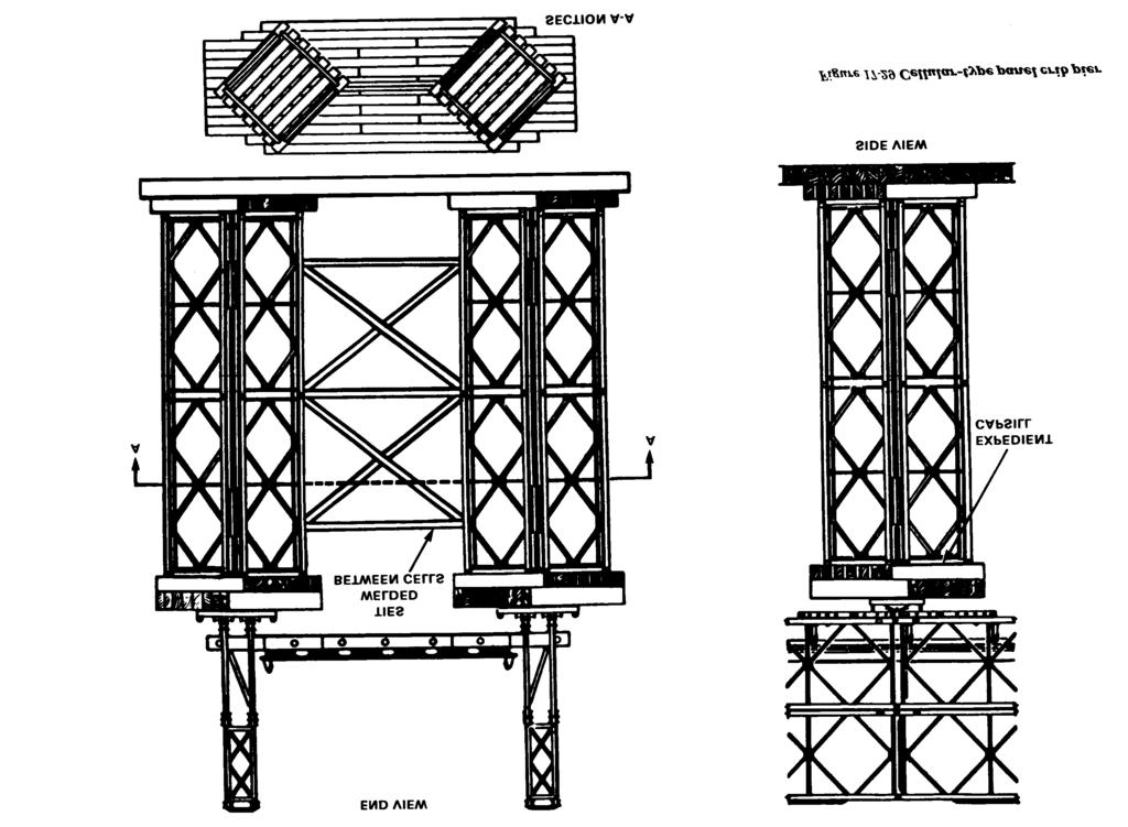
19 EXPEDIENT ASSEMBLY (NONSTANDARD TRUSSES) Expedient assembly of trusses and bracing can also be built for nonstandard truss arrangements. Trusses Expedient panel cribs can be built with panels transverse to the bridge axis, as in Figure This type of construction is useful when the pier is skewed or when the pier foundations are restricted. Two panels pinned end to end give a 20-foot (6.2 centimeters) pier width. In Figure trusses are braced together by bracing frames in every possible position, Bracing frames are overlapped at each end and 5-inch- (12.7 centimeters) long bolts replace standard bracing bolts. In lighter one-story piers, the two panels are connected by tie plates. The crib may be built in the form of two cellular columns, one under each side of the bridge, as in Figure (page 230). Each column is made of four vertical panels arranged in a square offset 45 degrees from the axis of the bridge. Weld chords of adjacent panels to angles. Cap panels with improvised capsills, and lay timber cribbing across capsills. The crib base is similarly constructed. Tie the two columns together by tie reds welded between them. Bracing More than one story of horizontal panels can be used if more expedient vertical cross bracing is added. Figure (page 231) shows sway braces in the vertical plane bracing a double-story pier to carry light loads. Bolt tie plates to one end of the sway 228 braces on an extension. Bolt lengthened sway to the underside of the top chord in the braces diagonally between the lower bracing. opposite inner truss (Figure 17-31, page 231). frame hole in the end vertical of one truss and the upper bracing frame hole of the end For heavier loads, channel sections welded vertical on the opposite truss. As an alter- across each end of the crib give a more rigid native, vertical sway braces can be used in cross brace (Figure 17-31). each story. Pin the braces to the bottom chord of the second panel, bend them up, and weld them


20 ASSEMBLY OF CRIB PIER Use the following sequence of procedures when building crib piers by manpower alone: 1 Lay out and accurately level pier foundation. Mark panel positions accurately. Position crib bearings where these are used. 2 Carry up panels for trusses on each side of crib and lay flat on base with female jaws pointing to bearings. Lift up panels and pin to bearings. 3 Fasten transoms, rakers, bracing frames, and sway braces in the first story. Check that panels are vertical and square to the centerline. 4 Construct a working platform of transoms and chess in the first story. Haul panels up singly and lay them flat on the platform with the female jaws opposite the top lugs of the first story. Lift each panel in turn and pin it into position. 5 Fasten transoms and bracing in the second story and again check that the crib is vertical and square to the centerline. 6 Repeat for the number of stories required. An improvised gin pole or davit may be used to lift panels and transoms to upper stones. 229
21 230
 high crib piers and the two lower stories of high piers. Assemble bays on the ground nearby, and lift the assembly into place by crane. For erecting higher piers, use a long-boomed crane.")
22 Use the following procedures when building piers with mechanical equipment: If site conditions permit, a truck-mounted crane can be used to erect 20-foot- (6.2 meters) high crib piers and the two lower stories of high piers. Assemble bays on the ground nearby, and lift the assembly into place by crane. For erecting higher piers, use a long-boomed crane. If pier construction is between existing high banks or piers, use cranes and high lines with winches on banks or existing piers to lift panels into place. If the bridge without the pier will carry the erection equipment, the pier can be constructed from the bridge. Use a truck crane or rope tackle to lower the panel over the side of the bridge into place on the pier. When all panels in the pier are in place, jack up the bridge over the pier to eliminate sag and allow placing of bridge seating. This last step can be eliminated by leaving the bridge on rollers at each abutment until after the pier is completed. Rollers must be blocked up enough to keep the bottom chord above the level of the top of the finished pier. For a continuous-span bridge, the pier can be built by working from the end of a cantilever span. 231
23 LAUNCHING OF BRIDGE Place rocking rollers on cribbing on top of the piers before launching the bridge (Figure 17-32). Push the bridge out over these rollers until the entire bridge is over all the spans. Jack up the bridge, remove rollers and cribbing, and then jack down the bridge onto its seatings on piers (Figure 17-33). A temporary working platform may have to be built for operating the jacks (Figure 17-34, page 234). If the bridge is to have independent spans, disconnect the girders at each pier. JACKING DOWN OF CONTINUOUS SPANS Where the distance through which the bridge has to be raised or lowered is more than a few inches, jacking has to take place on more than one pier at the same time. Since in this type of construction the whole girder is continuous, lifting through any distance progressively increases the length of bridge lifted and, thereby, increases the weight to be raised. This soon exceeds the capabilities of the jacks that can be brought into use on one pier. Where these conditions apply, a sequence of jacking on three piers at the same time, as described below, is the easiest method. This consists of raising the bridge through a smaller distance on each of the piers adjacent to the one on which the distributing beams are being fitted. 232


.")

24 The ends of the bridge are first jacked up and lowered onto suitable cribbing slightly above final level. Three complete jacking parties are then required for the intermediate piers, working from the near bank and in the following steps: 1 The first party, working on the first pier, lifts the bridge clear, removes the rollers and lowers the bridge onto the cribbing, the height of cribbing being the same as that used at the end of the bridge. 2 The second party does the same on the second pier while the first party jacks up on the first pier, fits distributing beams, and lowers the bridge to the original level (level of top of cribbing). 3 The third party completes step 1 on the third pier and the second party then fits distributing beams on the second pier. The first party then lowers the bridge onto the bearings of the first pier. 4 The first party completes step 1 on the fourth pier, the third party then fits distributing beams on the third pier, after which the second party lowers the bridge onto the bearings on the second pier. 233

25 This sequence of steps is continued throughout the length of the bridge. By this means, the bridge is raised by a slightly smaller amount on the two piers adjacent to the one on which the distributing beams are being fitted. Strict control of the jacking parties is essential, however, to enable the distributing beams to be fitted on the center pier. In the case of long bridges, it may be expedient to begin jacking on the center pier and work outwards toward the ends of the bridge. For this method, it is best to employ six jacking parties, three working toward each bank in the sequence of steps described above. Where the distance through which the bridge has to be lowered is such that it cannot be achieved in three stages, increase the number of jacking parties. 234
BRACING BRACING SECTION 7 SECTION 7
 If we are to learn from the past, it is clear that there is generally a lack of understanding of the purpose of roof bracing and who should be responsible for it. This has led to disputes, claims and,
GLOSSARY OF TERMS SECTION 8
 GLOSSARY OF TERMS SECTION 8 Anchor Bolt Angle Base Plate Bay Blocking CCB Centerline Chord Cladding Clip Closure Strip An A-307 steel bolt embedded in the concrete footing to anchor the base plate of the
A WORD ABOUT BRACING PART A - BUILDING A STRAIGHT, PILE BENT, OPEN DECK TRESTLE. Built in Place, Straight
 BUILDING LARGE SCALE TRESTLES You have many options when building a large scale trestle. The choices you make may be based on the prototype you are modeling; the era or industry you are modeling; or, simply
E N G L I S H GARDEN SHED. Assembly Instructions. Suitable for Models WITH VARYING DEPTHS
 GARDEN SHED Assembly Instructions Suitable for Models 6' Wide 8' Wide 0' Wide WITH VARYING DEPTHS GI0003 November 0 INSTALLATION ADVICE It's Not That Difficult! The construction of your shed isn't as complicated
3.1 General Provisions
 WOOD FRAME CONSTRUCTION MANUAL 107 3.1 General Provisions 3.1.1 Prescriptive Requirements The provisions of this Chapter establish a specific set of resistance requirements for buildings meeting the scope
RlGIDITY AND STRENGTH OF WALL FRAMES BRACED WlTH METAL STRAPPING
 RlGIDITY AND STRENGTH OF WALL FRAMES BRACED WlTH METAL STRAPPING information Reviewed and Reaffirmed March 1955 No. R1603 UNITED STATES DEPARTMENT OF AGRICULTURE FOREST SERVICE FOREST PRODUCTS LABORATORY
DUTCH GABLE FREESTANDING CARPORT
 DUTCH GABLE FREESTANDING CARPORT STRATCO OUTBACK ASSEMBLY INSTRUCTIONS. Your complete guide to building a FREESTANDING Outback DUTCH GABLE CARPORT BEFORE YOU START Carefully read these instructions. If
PRODUCT INFORMATION Penco Wide-Span Shelving
 PRODUCT INFORMATION Penco Wide-Span Shelving 2946 Larimer St. Denver, CO 80205 303-295-1100 / 800-373-7693 FAX 303-295-2464 Email info@snyderequipment.com www.snyderequipment.com Wide Span Shelving Penco
Strata. urniture. Addison Instructions. Parts in the Arm Box: Parts in the Body Box: Watch our assembly videos at
 1A Watch our assembly videos at www.strataf.com/videos.html Parts in the Arm Box: Arm - Outside View Arm - Inside View Corbels x 4 1B Parts in the Body Box: Back Deck x 1 Seat Deck x 1 Back Panel x 1 with
METHOD STATEMENT FOR THE CONSTRUCTION OF LIGHTWEIGHT HALLS
 METHOD STATEMENT FOR THE CONSTRUCTION OF LIGHTWEIGHT HALLS General The exact position of the structure has to be established. Please note that the difference in height must not exceed 1.5% in longitudinal
Experience the Hi-Lite Advantage
 Experience the Hi-Lite Advantage 12K Aluminum Shoring System INTRODUCTION The 12K Shoring System is primarily a hand-set system. It can also be handled with a crane, and may also be used quite successfully
6/19/2014. Milton Madison Bridge Slide. Project Partners. The Challenge. Aaron L. Stover, PE, SE Michael Baker Jr., Inc.
 Kentucky Society of Professional Engineers May 23 rd, 2014 Lexington KY Milton Madison Bridge Slide Aaron L. Stover, PE, SE Michael Baker Jr., Inc. Project Partners The Challenge Milton, KY Existing Bridge
MM340 Installation Instructions IMPORTANT SAFETY INSTRUCTIONS - SAVE THESE INSTRUCTIONS
 MM30 Installation Instructions IMPORTANT SAFETY INSTRUCTIONS - SAVE THESE INSTRUCTIONS Please read this entire manual before you begin. Do not unpack any contents until you verify all requirements on PAGE.
Installation Instructions for Vista Air Vertically Folding Walls
 Installation Instructions for Vista Air Vertically Folding Walls Use these instructions in conjunction with your shop drawings to see the specifics that are particular to the model you are installing.
Strata. urniture Watch our assembly videos at Denali Arms. Parts in the Arm Box: Hardware in this Box:
 1A Denali Arms Watch our assembly videos at www.strataf.com/videos.html Parts in the Arm Box: Arm - Outside View Arm - Inside View 1B Hardware in this Box: (80mm) x 8 Barrel Nuts x 8 x 8 Wood Buttons x
Suggested Reinforcement Detailing Practices Based on comments from R&D and ES ESS Committees
 Suggested Reinforcement Detailing Practices Based on comments from R&D and ES ESS Committees General 1. When detailing substructures, it is preferable not to use series bars unless necessary. The first
Sections & Details VOCABULARY
 1 Sections & Details VOCABULARY 1 ROOF FRAMING DETAIL RIDGE BOARD SHEATHING SHINGLES WEB FASCIA RAFTER (chord) SOFFIT SHEATHING STUD INSULATION DOUBLE TOP PLATE CEILING JOIST 2 FOUNDATION DETAIL STUD SHEATHING
Strata. urniture. Mission Rim Instructions. Parts in the Arm Box: Parts in the Body Box:
 1A Watch our assembly videos at www.strataf.com/videos.html Parts in the Arm Box: Arm - Outside View Arm - Inside View Corbels x 4 1B Parts in the Body Box: Back Deck x 1 Seat Deck x 1 with the Feet attached
Dura-Lock Roof System
 DLR-14 Dura-Lock Roof System Assembly and Installation Instructions Read the instructions before starting the job. They explain the steps required to produce a finished product that will meet factory specifications.
MM540 Installation Instructions IMPORTANT SAFETY INSTRUCTIONS - SAVE THESE INSTRUCTIONS
 MM50 Installation Instructions IMPORTANT SAFETY INSTRUCTIONS - SAVE THESE INSTRUCTIONS Please read this entire manual before you begin. Do not unpack any contents until you verify all requirements on PAGE.
ASSEMBLY INSTRUCTIONS TF Tent Flooring System. 125 Taylor Parkway Archbold, Ohio Phone: (419) Fax: (419)
 Fax: (419)") 125 Taylor Parkway Archbold, Ohio 43502 Phone: (419) 445-8915 Fax: (419) 445-0367 www.biljax.com TF-2100 Tent Flooring System ASSEMBLY INSTRUCTIONS ALL DRAWINGS ARE FOR ILLUSTRATION ONLY Revision: 1 1/21/16
125 Taylor Parkway Archbold, Ohio 43502 Phone: (419) 445-8915 Fax: (419) 445-0367 www.biljax.com TF-2100 Tent Flooring System ASSEMBLY INSTRUCTIONS ALL DRAWINGS ARE FOR ILLUSTRATION ONLY Revision: 1 1/21/16
General Guidelines:
 ASSEMBLY INSTRUCTIONS Congratulations on your new Patriot Dock purchase. This manual contains instructions to assemble basic dock configurations for use at typical residential shoreline application. Please
Chapter 23. Garage Construction
 Chapter 23. Garage Construction 23.1 ESTABLISHING CHALK LINES 23.2 MEASURING AND CUTTING WALL PLATES 23.3 MARKING WINDOW & DOOR LOCATIONS ON EXTERIOR WALL PLATES 23.4 MARKING STUDS ON EXTERIOR WALL PLATES
50 W ide. Future Trac G able E nd. Installation Instructions AIGE
 G able E nd W ide TopTec Products, LLC 7601 Highway 221 Moore, SC 29369 Phone: (800) 845-2830 Fax: (800) 921-77 e-mail: sales@toptecproducts.com www.toptecproducts.com AIGE 2003915 General Information
System 3000 specifications
 System 3000 specifications Scope: Materials: Type of Bookstack: This specification covers delivery and installation of steel library shelving of the bracket type. Height, depth and accessories shall be
1. Show the following information with additional information necessary to indicate shop compliance with the requirements of this section.
 SECTION 12360 LIBRARY SHELVING PART 1 GENERAL 1.01 SUMMARY A. Related Sections: 1. 06100 - Carpentry. 2. 09200 - Metal Studs, Lath, Suspension Ceiling, Plaster and Stucco. 3. 09660 - Resilient Tile Flooring.
Construction Tolerances - The following tolerances apply to cast-in-place structures:
 00540.40(b) Construction 00540.40 Tolerances - The following tolerances apply to cast-in-place structures: (a) Foundation Footings: (1) Lateral Alignment: Actual (as cast) location of the center of gravity:
ASSEMBLY INSTRUCTIONS
 ASSEMBLY INSTRUCTIONS PRINTED IN USA Assembly Instructions Include: P/N: LL-04-5 Step : Site Preparation Step 0: Guard Rail Installation Step : Leg Assembly Step : Stairs Step 3-8: Setting the Stage Step
REINFORCEMENT DESIGN FOR METAL BUILDING SYSTEMS
 REINFORCEMENT DESIGN FOR METAL BUILDING SYSTEMS By Donald L. Johnson, P.E. RETROFIT PROJECTS CAN BE NECESSARY FOR ANY NUMBER OF REASONS, though change in use is one of the most common. Change of use can
TREX ENHANCE RAILING (Also Applies to Trex Select Railing) Installation Instructions
 Installation Instructions") TREX ENHANCE RAILING (Also Applies to Trex Select Railing) NOTE: All Enhance Railing lengths are manufactured at CLEAR SPAN dimensions (spanning between space of posts): 7" for 6' clear span. Note that
TREX ENHANCE RAILING (Also Applies to Trex Select Railing) NOTE: All Enhance Railing lengths are manufactured at CLEAR SPAN dimensions (spanning between space of posts): 7" for 6' clear span. Note that
Clopay Models 835/837 Sliding Door System Installation Guide
 Clopay Models 835/837 Sliding Door System Installation Guide The aim of this instruction is to guide you through the process of construction and fitting of Sliding Doors. Due to the number of sizes available
table of contents Sliding Door Accessories Page Latches & Snuggers Stay Rollers Brackets & Stops
 table of contents Square Track & Accessories Pages 4-7 Square Track Options Page 4 Light Duty Track Page 4 Square Track Brackets Page 5 Square Track Accessories Page 5 Square Track Trolleys Page 6-7 Offset
Installation Guide. Capped Cellular PVC Fencing. Table of Contents. Storage and Handling Tools Needed Fence Layout and Locating Posts
 Capped Cellular PVC Fencing Installation Guide Table of Contents Storage and Handling Tools Needed Fence Layout and Locating Posts Installation instructions 4 x 4 Over Sleeve Post - 3.5 Rail Privacy Shadowbox
Strata. urniture. Adriana Instructions. Parts in the Arm Box: Parts in the Body Box: Watch our assembly videos at
 1A Watch our assembly videos at www.strataf.com/videos Parts in the Arm Box: Arm - Outside View Arm - Inside View 1B Parts in the Body Box: Back Deck x 1 Seat Deck x 1 with the Feet attached Back Panel
CURVED ROOF ASSEMBLY INSTRUCTIONS ATTACHED VERANDAH. Your supplementary guide to building an ATTACHED CURVED ROOF VERANDAH or PATIO BEFORE YOU START
 ROOF ATTACHED VERANDAH ASSEMBLY INSTRUCTIONS Your supplementary guide to building an ATTACHED ROOF VERANDAH or PATIO This set of instructions should be used in conjunction with the Stratco instruction
Sunrise Deck Assembly Instructions for Kingston Left
 Sunrise Deck Assembly Instructions for Kingston Left It s easiest to build the deck frame first like it will be lying on its back and then after all 4 legs and horizontals are in place, tip the deck toward
CEILING-MOUNTED MONORAIL ANCHOR TRACK SYSTEM Assembly and Operation Instruction Manual
 CEILING-MOUNTED MONORAIL ANCHOR TRACK SYSTEM Assembly and Operation Instruction Manual This manual is for various mounting types and plain and trussed track profiles. ISO 9001:2008 Registered Manual 103-0075
Mobile Weapons Storage System Specifications
 Mobile Weapons Storage System Specifications Whatever your weapon storage needs, Hi-Density s customized Weapons Storage System will be designed to fit your unique specifications. We recognize that security
SECTION R507 DECKS DECKING LEDGER BOARD BEAM. FOOTING BEAM SPAN CANTILEVER For SI: 1 inch = 25.4 mm FIGURE R507.2 DECK CONSTRUCTION
 SECTION R507 DECKS R507.1 Application. The provisions of this section shall provide prescriptive requirements for the design and construction of all uncovered, wood-framed, single-span exterior decks.
GROWING BETTER THROUGH DESIGN. 6ft Lean-To LEAN-TO. Assembly Instructions 04/02
 GROWING BETTER THROUGH DESIGN 6ft Lean-To LEAN-TO Assembly Instructions 04/02 6ft Lean-To Greenhouse Base Plan Introduction/Tools/Contents / / Contents This is a copy of our Lean-To greenhouse base plan.
MM750 Installation Instructions
 MM750 Installation Instructions IMPORTANT SAFETY INSTRUCTIONS - SAVE THESE INSTRUCTIONS Please read this entire manual before you begin. Do not unpack any contents until you verify all requirements on
A. Suggested Tool List
 These instructions are intended to be a basic guide to the installation and assembly of plate structures. Job site specific conditions may require other procedures. A Statement on Safety The assembly procedure
Assembly Instructions for a Double Climbing Frame
 Assembly Instructions for a Double Climbing Frame Step A: Lay out both bases with 8ft of spacing between them (See Diagram X) Once you are happy with the position of each base, remove bases and follow
CONTENTS TOOL LIST U P S I D E I N N O V A T I O N S, L L C RAMP AND STEP SYSTEM ASSEMBLY INSTRUCTIONS. Revised: June 2013
 U P S I D E I N N O V A T I O N S, L L C RAMP AND STEP SYSTEM ASSEMBLY INSTRUCTIONS TOOL LIST Required Tools: - Reciprocating Saw with Metal Cutting Blade - Drill - 7/16 Drill Bit for Metal Drilling -
ALL SEASON PATIO COVER
 ALL SEASON PATIO COVER 61 Where the All Season Patio Cover is to be attached to the home, create a level line showing where the top of the mounting rail is to be located. Install each section with the
Module 10 : Improvement of rock mass responses. Content
 IMPROVEMENT OF ROCK MASS RESPONSES Content 10.1 INTRODUCTION 10.2 ROCK REINFORCEMENT Rock bolts, dowels and anchors 10.3 ROCK BOLTING MECHANICS Suspension theory Beam building theory Keying theory 10.4
Glulam Connection Details
 T E C H N I C A L N O T E Glulam Connection Details Note: This version is superseded by a more current edition. Check the current edition for updated design and application recommendations. ENGINEERED
TRADITIONAL GABLE ATTACHED PATIO AND CARPORT. Your complete guide to building an ATTACHED Outback TRADITIONAL GABLE PATIO or CARPORT
 TRADITIONAL GABLE ATTACHED PATIO AND CARPORT STRATCO OUTBACK ASSEMBLY INSTRUCTIONS. Your complete guide to building an ATTACHED Outback TRADITIONAL GABLE PATIO or CARPORT BEFORE YOU START Carefully read
Assembly Instructions for a Double Climbing Frame
 Assembly Instructions for a Double Climbing Frame Step 1: Lay out both bases with 8ft of spacing between them (See Diagram Below) Once you are happy with the position of each base, remove bases and follow
Before Assembling the Storage Wall
 Chapter 1 Assembling the Lista Storage Wall Lista provides two types of standard Storage Walls: B251 and B255. The design, construction, assembly, and quality are identical for both types, however, B251
10x10 Trellis Pergola
 0x0 Trellis Pergola ASSEMBLY GUIDE Ver.0-7 Table of Contents PAGE Introduction & Overview...................................................... Pergola Materials Overview..............................................................
INSTALLATION GUIDE PermaTrak. Patented Product: U.S. Patent #5,906,084 #8,302,362 #8,522,505 #8,839,588 #9,096,975
 INSTALLATION GUIDE 2009-2017 PermaTrak. Patented Product: U.S. Patent #5,906,084 #8,302,362 #8,522,505 #8,839,588 #9,096,975 Table of Contents Project Overview Forward, Acceptability Criteria, Safety,
FORWARD FUSELAGE SIDES & REAR TOP SKINS
 FORWARD FUSELAGE SIDES & REAR TOP SKINS WORK REPORT Step No. Check Parts / Tools Qty Preparations. 1 [ ] 6F5-3 Upper Front Longerons 2 2 [ ] 6F5-5 Heel Support 1 3 [ ] 6F5-2 Front Floor Skin 1 3 [ ] Firewall
Range height adjustable assembly
 Table of contents Digital handset operation 3 Height adjustable bench kit 4-5 Cable carrier 6 Ganging tray and ganging rail 7 Height adjustable return frame kit 8 Cable entry pole 9 24 and 30 d worksurfaces
INSTALLATION INSTRUCTIONS
 1 INSTALLATION INSTRUCTIONS Prior to Assembling and Installing: 1) Field Check and verify that all components of the structure required for installation are in place per the approved shop drawings. Report
CENTER WING SECTION (CWS) WORK REPORT
 WORK REPORT") CENTER WING SECTION (CWS) WORK REPORT No. Check Parts / Description Qty PHASE 1: Preparations 1 [ ] 6V1-3 Rear ribs 2R & 2L 1 [ ] L Angle 6 2 [ ] 6V2-1 Rear Ribs.032 2R & 2L 2 [ ] 6V5-1 Gear Rib Doubler
CENTER WING SECTION (CWS) WORK REPORT No. Check Parts / Description Qty PHASE 1: Preparations 1 [ ] 6V1-3 Rear ribs 2R & 2L 1 [ ] L Angle 6 2 [ ] 6V2-1 Rear Ribs.032 2R & 2L 2 [ ] 6V5-1 Gear Rib Doubler
The General Principles of Detailed Design at Ruukki Construction Ltd. Julia Piiroinen
 The General Principles of Detailed Design at Ruukki Construction Ltd 1. The feasibilities of production at the workshops 2. Hot-rolled I-profile 2.1. Stiffeners 2.2. End plates 2.3. Lifting 3. Welded I-profile
FABA. Installation Instructions. Conductor Bar System. Publication #FABA-03 3/1/04 Part Number: Copyright 2004 Electromotive Systems
 FABA Conductor Bar System Installation Instructions Publication #FABA-03 3/1/04 Part Number: 005-1062 Copyright 2004 Electromotive Systems 1S 100 Z Installation Instructions Contents: Basic Diagram - -
GABLE ROOF CARPORT RECOMMENDED INSTRUCTION MANUAL
 GABLE ROOF CARPORT RECOMMENDED INSTRUCTION MANUAL Table of Contents Introduction 2 Components 3 Step 1a Marking out the Perimeter of the Carport with Footing only 3 Step 2a Footing Set-Out for Concrete
Safety Glasses Safety Gloves Ladders Measuring Tape Spirit Level String Line. Tin-Snips Rivet Gun Caulking Gun Silicone Socket Set
 BEFORE YOU START Carefully read these instructions and refer to them constantly during each stage of construction. If you do not have all the necessary tools or information, contact Stratco for advice.
INSTALLATION GUIDE. Outback. Flat Attached BEFORE YOU START ADDITIONAL MATERIALS TOOLS REQUIRED. VERAnDAHS PATIOS CARPORTS
 INSTALLATION GUIDE Outback VERAnDAHS PATIOS CARPORTS Flat Attached BEFORE YOU START It is important to check your Local Government Authority requirements before the installation of your new Stratco Outback
400A 40113V, 401A 40120V, & 401AL 40120VL ALUMINUM VERTICAL 4000 LB LIFT INCLUDES SCREW LEG ASSEMBLY INSTRUCTIONS
 12/11/07 PAGE 1 OF 12 400A 40113V, 401A 40120V, & 401AL 40120VL ALUMINUM VERTICAL 4000 LB LIFT INCLUDES SCREW LEG ASSEMBLY INSTRUCTIONS Thank you for purchasing our product! *Please read these instructions
Bulk Storage Rack Assembly Instructions
 Bulk Storage Rack Assembly Instructions Upright Frame Assembly Determine which end of the post goes up. The keystone slots on the front face of the post are wider at the top than at the bottom (see diagram
PUSH-PULL-PROPS. and accessories ROBUSTA-GAUKEL GMBH MOUNTING TECHNOLOGY &CO.KG
 PUSH-PULL-PROPS and accessories MOUNTING TECHNOLOGY ROBUSTA-GAUKEL GMBH &CO.KG MOUNTING TECHNOLOGY PUSH-PULL-PROPS AND ACCESSORIES INDEX General information...................... 3 Push-pull-prop Type
PATRIOT DOCKS ASSEMBLY INSTRUCTIONS
 6/1/2008 PATRIOT DOCKS ASSEMBLY INSTRUCTIONS Congratulations on your new Patriot Dock purchase. This manual contains instructions to assemble basic dock configurations for use at typical shoreline application.
10x10 Trellis Pergola
 0x0 Trellis Pergola ASSEMBLY GUIDE Ver.-007 Table of Contents PAGE 0x0 Trellis Pergola Introduction & Overview...................................................... Pergola Materials Overview..............................................................
OUTBACK FLAT ATTACHED VERANDAH PATIO CARPORT - INSTALLATION GUIDE BEFORE YOU START TOOLS REQUIRED ADDITIONAL MATERIALS
 BEFORE YOU START It is important to check your Local Government Authority requirements before the installation of your new Stratco Outback Flat Verandah. It is the builder s responsibility to ensure any
Gable HomeshedsTM INSTALLATION BEFORE YOU START TOOLS REQUIRED GUIDE LARGE SPAN. Council Approval. Before Starting
 INSTALLATION GUIDE Gable HomeshedsTM LARGE SPAN BEFORE YOU START Council Approval It is important to contact your local council before building your Stratco Gable Homeshed. You will have already received
Multi-Stage ASSEMBLY INSTRUCTIONS ST-8100 SERIES. 125 TAYLOR PARKWAY ARCHBOLD, OH PHONE: (419) FAX: (419)
 FAX: (419)") 125 TAYLOR PARKWAY ARCHBOLD, OH 43502 PHONE: (419) 445-8915 FAX: (419) 445-0367 www.biljax.com Multi-Stage ST-8100 SERIES ASSEMBLY INSTRUCTIONS ALL DRAWINGS ARE FOR ILLUSTRATION ONLY. PRINTED IN U.S.A.
125 TAYLOR PARKWAY ARCHBOLD, OH 43502 PHONE: (419) 445-8915 FAX: (419) 445-0367 www.biljax.com Multi-Stage ST-8100 SERIES ASSEMBLY INSTRUCTIONS ALL DRAWINGS ARE FOR ILLUSTRATION ONLY. PRINTED IN U.S.A.
Step 2 - Measure and install joist hangers every 16". See Figure "B" above. Fill every hole in each
 Adding a deck is one of the most useful projects a homeowner can do to improve their home. Each deck is different and presents it's own set of challenges, so contact us with unique questions if they are
Playground Assembly Instructions
 Before You Begin Playground Assembly Instructions Locate the playground set on firm, level ground. Assemble the playground on or close to its permanent location Two people are recommended to assemble the
bridges Installation Manual
 bridges Installation Manual 0 OHSAS 800:007 CGSB #0HS-009 ISO 900:008 CGSB #96- ISO 00:00 CGSB #EMS-00 Global Contract Inc. 6 Petrolia Road North York, Ontario, MJ X8 Visit us on the Internet at globalcontract.com
IIHS Side Impact Outrigger
 IIHS Side Impact Outrigger Assembly Procedure Base Assembly (14.3 lbs) The base assembly consists of a ¼ thick steel plate, a ¼ thick piece of polyethylene, and mounting fixtures for the upper and lower
ASSIGNMENT 2. Textbook Assignment: 2-1. Levels are designed for which of the following purposes?
 ASSIGNMENT 2 Textbook Assignment: "Levels," "Plumb Bulbs," "Scribers," "Squares," "Surface, Depth, and Height Gages," "Ring and Snap Gages and Gage Blocks," "Miscellaneous Measuring Gages," "Pliers and
MW&S STANDARD PROCEDURE
 FILE 1 of 6 SCOPE AND NATURE To provide for a uniform system of adjusting both jointed and welded rail for the prevention of buckling track where the rail was laid outside the preferred rail temperature
FORPARK AUSTRALIA
 FORPARK PRICE LIST AS AT 10/19/2018 Contents Prepare the site... 3 Equipment required for installation... 3 Fasteners... 4 Argonaut... 5 Carousel - With Rails/no rails... 6 Concord... 7 Cyclone... 8 Flying
Standard 25 Wide Structure
 Standard 25 Wide Structure Truss Arch Style 2 piece 12ft c/c typical Arch Depth 12 Webbing Diameter 1/2 1 run straight 2 runs straight Wind Brace - up to 120 8 Wind Brace - up to 192 12 Wind Brace - over
Assembly Instructions: Bencher Skylark
 Assembly Instructions: Bencher Skylark Tools Required: Pop Rivet Tool Tape Measure Hex Wrenches Screwdriver Several Disposable Rags Two Saw Horses Several boxes or bowls to hold fasteners and small parts
INSTALLATION GUIDE. Flat Roof Homesheds TM. Onto Concrete BEFORE YOU START TOOLS REQUIRED
 INSTALLATION GUIDE Flat Roof Homesheds TM Onto Concrete BEFORE YOU START It is important to check your Local Government Authority requirements before the installation of your new Stratco Flat Roof Homeshed.
Posi-Joist Installation Guide. A guide for storage, handling and installation of the MiTek Posi-Joist floor system
 Posi-Joist Installation Guide A guide for storage, handling and installation of the MiTek Posi-Joist floor system Posi-Joist Installation Details A B C D F E A Masonry Wall Connection Details Blockwork
Installation Instructions for the AlphaDeck Staging System
 Installation Instructions for the AlphaDeck Staging System Step 1 - Preparation A. Before setting up your system, determine the location where the stage will be installed and locate all the parts you will
BEST PRACTICE GUIDE. Socket Bases. Working with Concrete Slabs
 Working with Concrete Slabs When working with concrete slabs the barrier protection can be erected in three ways - with socket bases, adjustable slab edge brackets and multi slab clamps. Socket Bases 1
TREX SELECT RAILING. Installation Instructions PARTS
 RAILING NOTE : All Trex Select Railing lengths are manufactured at ON CENTER dimensions (spanning from center of each post): 67-5/8" (76.8 cm) for 6' (.83 m) on center, and 9-5/8" (35.3 cm) for 8' (.44
SHADOWBOX INSTALLATION FOR: Standard 6 H x 8 W Shadowbox Fence 5 x 5 Routed Posts Dog Ear or Straight-Edge Pickets 1.75 x 3.5 Rail
 SHADOWBOX INSTALLATION FOR: Standard 6 H x 8 W Shadowbox Fence 5 x 5 Routed Posts Dog Ear or Straight-Edge Pickets 1.75 x 3.5 Rail Storage and Handling Fence Preparation and Layout Locate and Set Posts
SWAY BRACE PIPE ATTACHMENT FIG. 010
 Function: Designed for bracing pipe against sway and seismic disturbance. The pipe attachment component of a sway brace system used in conjunction with a PHD Manufacturing structural attachment fitting,
MantelMount. TM1A Installation Instructions IMPORTANT SAFETY INSTRUCTIONS - SAVE THESE INSTRUCTIONS
 MantelMount TMA Installation Instructions IMPORTANT SAFETY INSTRUCTIONS - SAVE THESE INSTRUCTIONS TM Thank you for choosing the MantelMount television wall mount. Please read this entire manual before
Linear Hook- on Worksurfaces
 Linear Hook- on Worksurfaces Linear Hook-On Worksurfaces come in three depths and seven lengths. Different worksurfaces have different reqirements for installation that are outlined below. 27 inch deep
Section 1 Safety working at height
 Contents Section 1 Safety working at height. Section 2 Hi-Step package contents & parts identification. Section 3 Assembly. Section 4 Operation. Section 5 Maintenance. Section 6 Extender package contents
CertainTeed INSTALLATION GUIDE SIMTEK FENCE PRODUCTS. Fence Installation Guide 3', 4' & 6' High
 CertainTeed INSTALLATION GUIDE SIMTEK FENCE PRODUCTS Fence Installation Guide 3', 4' & 6' High INSTALLATION GUIDE These instructions are designed to assist both professional installers and do-it-yourselfers
Assembly Instructions
 18' W x 10' H or 12' H Peak Style Frame Assembly Assembly Instructions Before you start: 2+ individuals recommended for assembly, approximate time 3 hours. Recommended tools: Power Drill, Safety Glasses,
General Layout. Eng. Maha Moddather
 General Layout Eng. Maha Moddather mahamoddather@eng.cu.edu.eg Introduction Concrete Beam subjected to Bending Moment around Major Axis M x Compression d Concrete tensile strength is neglected A S Tension
GUARDRAIL ALUMINIUM SECURIGARD
 GUARDRAIL ALUMINIUM SECURIGARD ZZNO041UK April 2018 REQUIRED TOOLS Metal shears ( to remove the pallet bindings) Metal saw/batterypowered grinder Mallet Tape measure Cord Screwdriver Rivet gun CAUTION:
ESCONDIDO FIRE DEPT TRAINING MANUAL Section Truck Module Page 1 of 9 Ventilation Overview Revised
 Truck Module Page 1 of 9 INTRODUCTION Each firefighter must have a thorough knowledge of the proper methods used to ventilate a structure. Ventilation itself does not put out fires! However, effective
SunTrackerTwo Preparation
 TOLL FREE:(888)29-2705 FAX:(941)77-9460 info@eco-smart.com SunTrackerTwo Preparation Cutting Holes and Preparing Curbs T.G.I Or Truss CIRALIGHT INSTALLATION MANUAL Page 1 Cutting Holes and Preparing Curbs
Slope Floor. Measurement Methods
 Slope Floor Measurement Methods Many chair installations are on sloped floors. Hussey Seating uses five different feet for floor mount chairs based on the degree of slope. The slope of the floor is a critical
SPACE-LIFT DAYTONSUPERIOR.COM APPLICATION GUIDE. Jump Forming System
 SPACE-LIFT Jump Forming System APPLICATION GUIDE The Space-Lift system is a fully-engineered jump form system intended for concrete shear wall applications. The system consists of frame components and
Evorail Guardrail has Evolved
 Evorail Guardrail has Evolved Introduction o About Evorail o Legislation & Hierarchy of Fall Protection o Evorail The Systems Evorail Standard Evorail Radius Evorail Collapsible Evorail Top Fixed Evorail
712 - STRUCTURAL STEEL CONSTRUCTION SECTION 712 STRUCTURAL STEEL CONSTRUCTION
 SECTION 712 STRUCTURAL STEEL CONSTRUCTION 712.1 DESCRIPTION Fabricate and erect the structural steel as designated in the Contract Documents. See SECTION 705 for fabrication of structural steel. Provide
 BHARAT HEAVY ELECTRICALS LIMITED TIRUCHIRAPALLI 620 014 QUALITY ASSURANCE SIP:NP:02 /02 PAGE : 1 Of 11 TRIAL ASSY OF COLUMNS, CEILING GIRDERS, MONORAIL & RUNWAY BEAMS REV. DATE PREPARED REVIEWED APPROVED
Assembly Instructions for 12x16 Floating Dock
 Assembly Instructions for 12x16 Floating Dock www.rollingbarge.com Congratulations on the purchase of your Floating Dock kit. This kit includes all the aluminum frame parts, and all the fasteners. You