GUARDRAIL ALUMINIUM SECURIGARD
|
|
|
- Gloria Sparks
- 5 years ago
- Views:
Transcription


1 GUARDRAIL ALUMINIUM SECURIGARD ZZNO041UK April 2018 REQUIRED TOOLS Metal shears ( to remove the pallet bindings) Metal saw/batterypowered grinder Mallet Tape measure Cord Screwdriver Rivet gun CAUTION: For crane handling on a flat roof, do not exceed the maximum permissible loading for the roof and the structure Page 1 / 10
2 WARNING: Any activity undertaken at a height is dangerous and may lead to accidents or serious injury. The practicing and learning of techniques for the use of appropriate safety equipment is your responsibility. Workers using Personal Protective Equipment should be trained appropriately, as per EU Directive 89/656/CEE Section II, Articles 4.8. BEFORE STARTING WORK: Before undertaking any work, the installer must organise the worksite in such a way as to ensure that the installation work is carried out in accordance with the regulatory safety conditions, notably with reference to Labour Regulations. The installer must set up the collective and/or personal protection required for this purpose. He must ensure that the equipment to be fitted complies, in terms of type and quantity, to the equipment detailed in the preliminary study. Conditions For Use: - Access to the roofs must not be permitted for the public. - Roof slopes (pitch) less than 10 or 17%. (Valid for self-supporting guardrails only) - Moderate traffic levels on the flat roof. (Access for maintenance) - Structure compatible with the additional loading (see technical data). Any installation without the maximum interval distance of 1500 mm and/or the dimensions indicated in the positioning of corners plan will lead to the declaration of a non-conformity involving the protective system MODELS OF THE GUARDRAILS CONCERNED Aluminium guardrail / Steel fastenings (Alustyle) Wall mounting on Z150 on Z250 on baseplate onto steel roof sheet Self-supporting model Aluminium guardrail / Aluminium fastenings Wall mounting on baseplate Notice de montage ZZNO041UK / Guardrail Aluminium SECURIGARD / April 2018 / Page 2 / 10
 2 3 1 Aluminium rail, lenght 3m MAFSGAC01/19B MAFSGAC01/16B 2 Claimp rail Ø40 MAFSGAC05/10-3 Ring")


3 ACCESSORIES ZZNO081 Désignation Handrail Ø 40 Intermediate rail Ø 30 1 (Ø40)? 1 (Ø30) Aluminium rail, lenght 3m MAFSGAC01/19B MAFSGAC01/16B 2 Claimp rail Ø40 MAFSGAC05/10-3 Ring MAFSGAC05/ Inter-rail Ø30 MAFSGAC05/08 5 Adjustable corner junction MAFSGAC24/02B MAFSGAC24/12B 6 Free-end piece MAFSGAC03/07B Post cap MAFSGAC05/03 8 Base clip MAFSGAC04/04 9 Concrete base S1 MLFSGAC04/ Rail cap MAFSGAC05/02 MLFSGAC05/01 11 Self-tapping screw 4.8x19 MLFSGAC06/11 12 Baseboard joints MAFSGAC07/04B Coloured rail fitting tool MLFSGAC05/07 MLFSGAC05/06 14 Aluminium baseboard MAFSGAC14/01B 15 Angle piece for baseboard MAFSGAC07/02 16 Non-slip sole MAFSGAC21/02 17 Wall mounted end piece MAFSGAC13/04B MAFSGAC13/05B Baseboard support (straight or curved stabilic) Baseboard support (tilted stabilic) MAFSGAC07/06 MAFSGAC07/08 THE LAYOUT OF GUARDRAILS Before fitting the protection, clean the area around the intervention, removing any element likely to interfere with the fitting of the posts or damaging the existing leak-proof membrane. For self-supporting guardrails, if the roof is fitted with a heavy layer of protection or a gravel surface, clear the zone from an area of 1800 mm min. No gravel or other material liable to puncture the membrane must be found below the area of the self-supporting guardrail. Installations must respect the maximum centreline distance of 1500 mm. This distance may be reduced to position the guard rail posts uniformly across the length of a roof. At the corner points, the guardrails must be place as defined in the instructions below. A non-respect for these dimensions may lead to a nonconformity for the protection. Trace out, on the floor or roof edge wall, the location of the posts, starting with the corner points and respecting the distance given below. CAUTION: For self-supporting guardrails, the posts must not rest on the sealing membrane strengthening bracket. Trace the alignment of the posts on the ground, leaving a gap of 110 mm mi. from the edge of the membrane. NO Notice de montage ZZNO041UK / Guardrail Aluminium SECURIGARD / April 2018 / Page 3 / 10
 Valid for")


 1500 (round the result to the")


4 Self-supporting guardrail Fixed guardrail on tanked roof Convex corner Convex corner (valid for wave of 250 mm or 300 mm) Valid for all SECURIGARD guardrails Convex corner Concave corner Against a wall Max. distance between empty sections Spread of posts along a length Uniformly position the posts along the lengths, calculating the interval distance using the calculation below. Length L Calculation of the number of posts: Centreline distance E Centreline distance E Centreline distance E Centreline distance E No. of posts = 1 + LLLLLLLLhtt (LL) 1500 (round the result to the next unit) Calculation of the interval distance (E): Interval distance between posts = LL NNNNNNNNNNNN oooo pppppppppp 1 FASTENING/FITTING GUARDRAILS Self-supporting guardrails OK! NO! Lift the bases, ALU markings upwards, and insert the offset arm into the aluminium opening Reposition the posts above the marking point. Repeat the operation for all posts Caution: the marking information must remain visible Notice de montage ZZNO041UK / Guardrail Aluminium SECURIGARD / April 2018 / Page 4 / 10


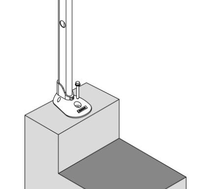
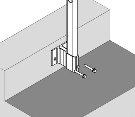
5 Fastening using Z150/250 Wall mounting Plate mounting On a concrete wall edge, drill and attach the guardrail 60 mm from the inside edge of the wall, using mechanical or chemical anchors suitable for the support On a concrete wall edge, drill and attach the guardrail 60 mm from the top of the wall, using two mechanical or chemical anchors suitable for the support On a concrete wall edge, drill and attach the guardrail 60 mm from the top of the wall, using two mechanical or chemical anchors suitable for the support On a running steel rail, attach the guardrail using four self-tapping screws On a concrete wall edge, drill and attach the guardrail 60 mm from the top of the wall, using two mechanical or chemical anchors suitable for the support On a concrete wall edge, drill and attach the guardrail 60 mm from the top of the wall, using a mechanical or chemical anchor suitable for the support GUARDRAILS ASSEMBLY CLIC! CLIC! Insert the lower rails into the posts, starting by corner angle. Repeat with the upper rail Fit the Ø30 rail sections together Insert the corner junction in rail with rivets Notice de montage ZZNO041UK / Guardrail Aluminium SECURIGARD / April 2018 / Page 5 / 10


6 CLIC! Fit the Ø40 rail sections together Dealing with corners: Cross the rails, mark the overlap and cut the rail 43 mm back Drill a Ø7 hole crossing at 46 mm from the end of Ø40 rail. For an intermediate rail, drill a hole at 25 mm Insert the corner junction in rail with rivets These 4 steps are similar to corners adjustments of Ø30 intermediates rails. Only the drilling dimensions changes : to 25mm for a Ø30 rail instead of 46 mm for a Ø40 rail. Connect the next rails to corners junctions Notice de montage ZZNO041UK / Guardrail Aluminium SECURIGARD / April 2018 / Page 6 / 10
, the rail must be recut at between 413 and 380 mm.")
. Assemble with interrail. Drill the hand rail (page 6) and finish by riveting the elements.")

7 Free-end assembly Cut the top rail 282 mm from the post. Cut the lower rail 38 mm from the post and insert the ring For an interval distance of 500mm (between rails), the rail must be recut at between 413 and 380 mm. Connect the free-end piece to the guardrail starting with the intermediate rail Insert the Ø30 mm rings in first time the intermediate side of the railing assembled. In second time, put the other one rings in the free-end pieces (opposite side to the drilling). Assemble with interrail. Drill the hand rail (page 6) and finish by riveting the elements. Final assembly with anchors Cut the rails 100 mm from the post and insert the anchors Wall mounted ending Drill the wall and fixe (anchors not included) the ending to it. Then drill and rivet the rails on the endings. Finalising the assembly (must be completed to assure a compliant assembly) Before locking the posts, the rails and the concrete base in place, make sure the protection is perfectly aligned. If necessary, adjust the heights of the posts at their bases to assure perfectly horizontal rails Self-supporting guardrails Conclude the assembly process by inserting the clips into the concrete bases. Insert the caps into all posts. Notice de montage ZZNO041UK / Guardrail Aluminium SECURIGARD / April 2018 / Page 7 / 10
 Self-supporting guardrails and")


8 FITTING THE BASEBOARDS (FOR ROOF EDGE WALLS < 100 mm) Self-supporting guardrails and guardrails mounted on plates: Lay out the baseboards and holders, starting with an angle. Insert the offset plate into the baseboard and attach the guardrail to the baseboard, using the baseboard jumper and the screw. Pre-tighten the assembly. Guardrail fixed onto a tank Pre-tighten the 2 screws through the base of the guardrail (see above) Fit the baseboards together using the junction pieces Baseboard angles are handled by joining the angle pieces, first having cut the baseboards as they cross the angle. For self-supporting guardrails or plates, you must add a self-tapping screw to lock the position of the baseboard vertically Adjust the height of the baseboard (5 mm max.) to assure there is no direct contact with the sealing membrane. Tighten the assembly. Notice de montage ZZNO041UK / Guardrail Aluminium SECURIGARD / April 2018 / Page 8 / 10
 using a wooden spacer Use an inter-rail to connect the two pieces I need to replace an intermediate rail, how do I do this?")
 using a wooden spacer Use an inter-rail to connect the two pieces My intermediates rails will not link together.")

9 FAQ I need to cut a rail, how do I do this? Cut the rail as required, but ensure the cut is straight. Insert a Ø30 mm ring (MAFSGAC05/06) using a wooden spacer Use an inter-rail to connect the two pieces I need to replace an intermediate rail, how do I do this? Cut the inter-rail piece using a saw Insert the ring and the remaining part of the interrail piece into the rail, by around 60 mm Insert a Ø30 mm ring (MAFSGAC05/06) using a wooden spacer Use an inter-rail to connect the two pieces My intermediates rails will not link together. / the ring is pushed in too far, Check whether the rail actually holds a ring. If not, add, using a wooden spacer Cut the rail flat with the ring Push it further in, by approx. 60 mm, and add a new ring using a wooden spacer The rail end is not straight. Push the ring slightly into the hole a little further and cut the rail flat against the ring. Notice de montage ZZNO041UK / Guardrail Aluminium SECURIGARD / April 2018 / Page 9 / 10


10 I need to cut and realise a new handrail junction, how do I do this? Cut the rail at the right dimensions, make sure that the cutting are straight. Warning : never cut of the narrow side Drill a Ø7 hole crossing at 46 mm from the end of rail Connect the new junction Insert the corner junction in rail with rivets I need to do corner junction, how do I do this? Cut the rail at the right dimensions, make sure that the cutting are straight. Drill a Ø7 hole crossing at 46 mm from the end of Ø40 rail. For an intermediate rail, drill a hole at 25 mm Insert the corner junction in rail with rivets When adjusting products on the worksite (cuts, drillings, etc.), Don t forget to remove any fragments left Notice de montage ZZNO041UK / Guardrail Aluminium SECURIGARD / April 2018 / Page 10 / 10
Wall mounting bracket
 Install Manual Wall mounting bracket Please read this manual carefully before operating your set and retain it for future reference. OSW200 P/NO : MFL63640578 (1502-REV01) www.lg.com COMPONENT Install
Series 1100 Aluminum Door Canopy
 Series 00 Aluminum Door Canopy with Support Arms It is our recommendation that you read instructions carefully prior to assembly and installation. Series 00 with Support Arms MOUNTING BAR (A) TOP TRIM
Series 1500 Aluminum Door Canopy
 Series 500 Aluminum Door Canopy with Sidewings It is our recommendation that you read instructions carefully prior to assembly and installation. Series 500 with Sidewings mounting bar (A) top trim (B)
CONTENTS TOOL LIST U P S I D E I N N O V A T I O N S, L L C RAMP AND STEP SYSTEM ASSEMBLY INSTRUCTIONS. Revised: June 2013
 U P S I D E I N N O V A T I O N S, L L C RAMP AND STEP SYSTEM ASSEMBLY INSTRUCTIONS TOOL LIST Required Tools: - Reciprocating Saw with Metal Cutting Blade - Drill - 7/16 Drill Bit for Metal Drilling -
Assembly Instructions
 Selling Station Assembly Instructions View from above without top A B C D Rounded finished corners on A & D Square unfinished 3-sides on B & C Selling Station Components (2) 2' x 6' Side s Have a channel
ALL SEASON PATIO COVER
 ALL SEASON PATIO COVER 61 Where the All Season Patio Cover is to be attached to the home, create a level line showing where the top of the mounting rail is to be located. Install each section with the
Installation Instructions - Model V4JSD 1
 Installation Instructions - Model V4JSD 1 Support Assemblies: Parts list: (Note see enclosed cut sheet for quantities and dimensional information) A vertical structural member (1 ½ x 1 ½ modular frame)
GlideRite Retractable Cover System For HotSpring & Tiger River Spas (except Classic & pre-2000 Landmark Spas)
") List of Contents Quantity Description 12 #10 x 1 ½ Flat Head Phillips Screw (see pg. 2) 2 #10 x ½ Pan Head Phillips Screw (see pg. 2) 8 ¼ x 2 ½ Lag Bolt (see pg. 2) 7 ¼ 20 x 5 / 8 Hex Head Bolt (see pg.
List of Contents Quantity Description 12 #10 x 1 ½ Flat Head Phillips Screw (see pg. 2) 2 #10 x ½ Pan Head Phillips Screw (see pg. 2) 8 ¼ x 2 ½ Lag Bolt (see pg. 2) 7 ¼ 20 x 5 / 8 Hex Head Bolt (see pg.
SAM. Model: STV-C65 LCD Mobile Visualized Stand Instruction Manual. Weight Capacity: 1251bs / 56.7kg Suits LCD Flat Panel Display: 42"-55" Page 20
 SAM Model: STV-C65 LCD Mobile Visualized Stand Instruction Manual Weight Capacity: 1251bs / 56.7kg Suits LCD Flat Panel Display: 42"-55" 20 Step 6 LCD Mobile Lift Stand Model: STV-C65 Cable management
Your order will be shipped with the supports and rail components packaged inside the ramp package. Each accessory package is labeled.
 instructions About Your Order. Your order will be shipped with the supports and rail components packaged inside the ramp package. Each accessory package is labeled. Check the Order Before the Carrier leaves!
SILVERBACK INSTALLATION MANUAL
 SILVERBACK INSTALLATION MANUAL R-SERIES SOLAR RACKS T OLL FREE 866-766-3727 WWW.ROOFSCREEN.COM Introduction... 2 The Silverback Solar Racking System... 2 This manual... 2 Application... 2 System Overview...
Installation Instructions for Vista Air Vertically Folding Walls
 Installation Instructions for Vista Air Vertically Folding Walls Use these instructions in conjunction with your shop drawings to see the specifics that are particular to the model you are installing.
 SUPREME WALL GARDEN ASSEMBLY INSTRUCTIONS 24/08/16 www.hallsgreenhouses.com Please refer to website for the most up to date instructions. SAFETY WARNING 1. Always wear protective glasses, shoes, gloves
Assembly Instructions 10 X 10 Aluminum Roof Support
 Assembly Instructions 10 X 10 Aluminum Roof Support Aluminum Roof Support Bolt Package 16-5/16 X 2 ¼ SS Bolt 24-5/16 X 1 SS Bolt 40-5/16 SS Nylon Lock Nuts 16-5/16 SS Flat Washers 28-4 ½ Wood Screws 36-1
STACKING MULTI-SLIDE DOOR SYSTEM INSTALLATION INSTRUCTIONS
 STACKING MULTI-SLIDE DOOR SYSTEM INSTALLATION INSTRUCTIONS 1290363 Revision 1 12/16 Page 1 Weather Shield Mfg., Inc. NOTICE CAUTION! Failure to install and maintain our product according to these instructions
Display Shelving Installation Instructions
 Display Shelving Installation Instructions Top Rail (R-T) Back (BE) (R-C) Splicer Rail (R-S) 78 H to 120 H only Uprite (U) Uprite End Trim (UET) Shelf Back (BE) Base End Trim (BET) (R-C) 96 H to 120 H
Assembly and Installation Guide
 The Easy Hang Closet Solution SM Install Your elfa In An Instant. Enjoy The Benefits For A Lifetime. Basic Tools For elfa Assembly and Installation Level Hand or Power Drill Drill Bits 1/8", 3/8", 5/16"
Wall mounting bracket
 Install Manual Wall mounting bracket Please read this manual carefully before operating your set and retain it for future reference. OTW150 P/NO : MFL63640588 (1503-REV01) www.lg.com COMPONENT Wall mount
Installation Instructions for. Before You Begin TOOLS REQUIRED
 Composite Railing System STEP-BY-STEP Installation Instructions for Spectrum Composite Railing Virtually maintenance free 20-year warranty EverNew Spectrum Railing system is designed to work with a number
Universal flat-panel mount
 I N S T A L L A T I O N M A N U A L Universal flat-panel mount www.christiedigital.com PM 2004/ REV 02 Contents - Assembly drawing - Fine tune tilt adjustments - Parts list - Installing the adapter plate
EASY POOL STEP (NE113)
") EASY POOL STEP (NE113) FOR USE WITH: EASY POOL STEP (NE113) (1 CARTON) EASY POOL STEP WITH OUTSIDE LADDER (NE126) EASY POOL STEP ENTRY SYSTEM (NE138) (With Gate) (4 CARTONS) Above are the options available
EASY POOL STEP (NE113) FOR USE WITH: EASY POOL STEP (NE113) (1 CARTON) EASY POOL STEP WITH OUTSIDE LADDER (NE126) EASY POOL STEP ENTRY SYSTEM (NE138) (With Gate) (4 CARTONS) Above are the options available
Free-standing Barrial Installation of free-standing Barrial
 Installation of free-standing Barrial Important comments Detailed setting out drawing All Barrial products are supplied with a detailed setting out drawing and a parts list. The detailed setting out drawing
Mount to the Wall INSTALLATION MANUAL
 Mount to the Wall 15 Locate the Wooden Studs This step applies to wooden stud wall installation only. Determine and mark the exact locations of two stud centers on the wall. Wooden studs should be spaced
Horizontal Cable Systems
 ALUMINUM RAILING INSTALLATION INSTRUCTIONS v2012 orizontal Cable Systems 1) Check Contents Of Packages: Verify that all parts have arrived and that they match the packing list. 1A) Coastal applications:
DUTCH GABLE FREESTANDING CARPORT
 DUTCH GABLE FREESTANDING CARPORT STRATCO OUTBACK ASSEMBLY INSTRUCTIONS. Your complete guide to building a FREESTANDING Outback DUTCH GABLE CARPORT BEFORE YOU START Carefully read these instructions. If
PORCH-LOC INSTALLATION INSTRUCTIONS
 PORCH-LOC INSTALLATION INSTRUCTIONS 2017 HB&G Building Products, Inc. Porch-Loc Installation Instructions NOTE: DISCARD THE INSTALLATION INSTRUCTIONS AND HARDWARE THAT CAME IN YOUR PERMAPOST PACKAGING
Figure 1. RAILING INSTALLATION The following instructions describe the installation of three types of railing sections: Line, Stair, and Angled
 Veranda Railing System Veranda railing systems are designed to work with a number of different decking materials and surfaces. Before initiating any project, obtain a copy of your local building codes
Privacy Wall Glass Selections - Polished Edge Slider Door
 Privacy Wall Glass Selections - Polished Edge Slider Door 3/6" HEX BIT PUTTY KNIFE #2 ACR BIT SUCTION CUP HOLDERS DOOR LEAF: Satin Tempered Clear Tempered LOCTITE 425 SIDE LIGHT ETCHED GLASS STYLES: Satin
Figure A. Figure B. Figure C. Figure D
 Xsite 1 Power/Data Tile and Components Tools Required Tape Measure Cordless Drill/Driver #2 Phillips Screw driver bit Rubber Mallet Flat Blade Screwdriver Figure A Hardware Required Provided as shown Installation
How to Install Custom Real Wood and Faux Wood Blinds
 Before you begin your installation: READ ALL INSTALLATION INSTRUCTIONS! Make sure that you have all tools and hardware needed for installation. Check the installation surface (wall, ceiling, or window
lindab we simplify construction LindabSandwichPanels Installation instructions PIR Panels
 lindab we simplify construction LindabSandwichPanels Installation instructions PIR Panels Assembly instructions Before you start Check that the panel support structures are level. Position the packages
EASY-IN POOL STEP SYSTEM NE132
 EASY-IN POOL STEP SYSTEM NE132 This instruction manual features multiple guides for the step unit components. 7939 EASY POOL STEP (NE113) FOR USE WITH: EASY-IN POOL STEP (NE126) 6492 PARTS & HARDWARE FOR
INSTRUCTION MANUAL DWX723-XE HEAVY-DUTY MITER SAW STAND FINAL PAGE SIZE : 8.5IN X 5.5IN
 INSTRUCTION MANUAL DWX723-XE HEAVY-DUTY MITER SAW STAND FINAL PAGE SIZE : 8.5IN X 5.5IN DWX723-XE MITER SAW STANDS Components List A. Beam B. DW7231 Miter saw mounting brackets C. Extension arm D. DW7232
ClearVue Roofing System Technical Manual
 Technical Manual Components CLEARVUE RAFTER BRACKETS CV-02 2 Components CLEARVUE EXTRUSIONS CV-03 3 Components END PLATES - 6mm SHEET CV-04 4 Components END PLATES - 8mm SHEET CV-05 5 Components MECHANICAL
MM540 Installation Instructions IMPORTANT SAFETY INSTRUCTIONS - SAVE THESE INSTRUCTIONS
 MM50 Installation Instructions IMPORTANT SAFETY INSTRUCTIONS - SAVE THESE INSTRUCTIONS Please read this entire manual before you begin. Do not unpack any contents until you verify all requirements on PAGE.
a.k.a. casegoods instructions
 a.k.a. casegoods instructions a a.k.a. workwall installation IMPORTANT NOTES Failure to install product according to installation instruction will result in loss of warranty. Tools required for assembly
INSTALLATION INSTRUCTIONS
 Tools required for the installation. A. Core Drill 87mm Drill bit B. Tape measure C. Spirit Level D. Marking pen E. Caulking gun F. Cutting Pliers G. Cordless Drill and Philips head bit, 5mm Drill bit.
GlideRite Retractable Cover System For Hot Spot Spas (SE & SLX only)
") List of Contents Quantity Description 12 #10 x 1 ½ Flat Head Phillips Screw (see pg. 2) 2 #10 x ½ Pan Head Phillips Screw (see pg. 2) 8 ¼ x 2 ½ Lag Bolt (see pg. 2) 7 ¼ 20 x 5 / 8 Hex Head Bolt (see pg.
List of Contents Quantity Description 12 #10 x 1 ½ Flat Head Phillips Screw (see pg. 2) 2 #10 x ½ Pan Head Phillips Screw (see pg. 2) 8 ¼ x 2 ½ Lag Bolt (see pg. 2) 7 ¼ 20 x 5 / 8 Hex Head Bolt (see pg.
Projector Ceiling Mount
 INSTALLATION MANUAL Projector Ceiling Mount PID:3010 PID:5466 20kg (44lbs) RATED CAUTION: DO NOT EXCEED RATED LISTED WEIGHT. SERIOUS INJURY OR PROPERTY DAMAGE MAY OCCUR! ISSUED: FEB. 2013 NOTE: Read the
MM340 Installation Instructions IMPORTANT SAFETY INSTRUCTIONS - SAVE THESE INSTRUCTIONS
 MM30 Installation Instructions IMPORTANT SAFETY INSTRUCTIONS - SAVE THESE INSTRUCTIONS Please read this entire manual before you begin. Do not unpack any contents until you verify all requirements on PAGE.
LAWN AND GARDEN GREENHOUSE
 MODELS# OG0AL8-BKE OGAL-8 OGrow Walk-in ' x 8' LAWN AND GARDEN GREENHOUSE With Heavy Duty Aluminium Frame MANUAL VERSION # Grow r! e h t e g To Let's Thank you for purchasing the OGROW greenhouse Follow
TONNEAU INSTALLATION INSTRUCTION
 TONNEAU INSTALLATION INSTRUCTION Mitsubishi MQ Triton Dual Cab With Headboard, No Sports Bars Clip On Cover July 2015 Current Package includes Part number: STO10642 1 X Tonneau cover 2 x Bar Brackets (300474)
NEW equinox INSTALLATION GUIDE Issue
 NEW equinox INSTALLATION GUIDE Issue 1 CONTENTS If in doubt at any stage 1. Preparing the ring beam 2 2. Installing the framework 3 3. Insulation and waterproofing 7 4. Tile application: Steel tiles 9
INSTALLATION MANUAL H A
 INSTALLATION MANUAL CABINET RACK CR-43-6 (4-UNIT SIZE) Be sure to read this installation manual thoroughly before installing this Cabinet Rack. For the mounting procedures of the components and the relevant
Lunette 2 Series. Curved Fixed Frame Projection Screen. User s Guide
 Lunette 2 Series Curved Fixed Frame Projection Screen User s Guide Important Safety and Warning Precautions Please follow these instructions carefully to ensure proper maintenance and safety with your
Aluminum Railing Installation. Glass Railing Spindle Railings Intimacy Railings and Panels
 Aluminum Railing Installation Glass Railing Spindle Railings Intimacy Railings and Panels This information in this manual will help you to Better understand our product line. Give you guidelines for an
ATLANTIS RAIL Contact Information
 ATLANTIS RAIL Contact Information Customer Service (800) 541-6829 (508) 732-9191 Spectrum System Installation Instructions Atlantis Rail s Spectrum System is an easy to install, universal cable railing
INSTALLATION INSTRUCTIONS
 POST THIS WARNING IN A CONSPICUOUS PLACE, CLEARLY VISIBLE TO ALL STORE PERSONNEL Install all components according to installation instructions. READ BEFORE ASSEMBLING WARNING FOR YOUR SAFETY Installation
PVC Fencing Install Instructions
 PVC Fencing Install Instructions Step 1-Pounding the Galvanized Steel Posts Call your local area utility company to come mark underground lines before any digging or pounding any posts into the ground.
FW / FIG Partition Kit(s) Installation Instructions
 Installation Instructions") FW / FIG Partition Kit(s) Installation Instructions This instruction explains how to join 8 in. and 10 in. top piping partitions to FIG and FW merchandisers. Do not remove the shipping braces until the
FW / FIG Partition Kit(s) Installation Instructions This instruction explains how to join 8 in. and 10 in. top piping partitions to FIG and FW merchandisers. Do not remove the shipping braces until the
Assembly Instructions 10 X 10 Aluminum Frame Building
 Assembly Instructions 10 X 10 Aluminum Frame Building 27 97 9 8 47 36 74 52 10 10 X 10 Square Building W/ Dome Includes: The Steel Entry Door with a Dead Bolt Lock assembly and Aluminum Door Frame. Metal
ALDoor DOUBLE DOOR INSTALLATION
 Assembly Top Jamb Side Jamb Horizontal Vertical Vertical Jamb Brackets General Layout 15-20 mm Red (LHS) Cable Drum Red Cone Black Cone Black (RHS) Cable Drum 75 mm Minimum Left Hand Side Bearing Plate
TIP FOR GETTING STARTED
 Tip for getting started TIP FOR GETTING STARTED Be careful not to drill into any electrical wires, ductwork, plumbing or other damagable components. If you have any questions on the locations of these
E N G L I S H GARDEN SHED. Assembly Instructions. Suitable for Models WITH VARYING DEPTHS
 GARDEN SHED Assembly Instructions Suitable for Models 6' Wide 8' Wide 0' Wide WITH VARYING DEPTHS GI0003 November 0 INSTALLATION ADVICE It's Not That Difficult! The construction of your shed isn't as complicated
IMPORTANT!!! ASSEMBLY ASSEMBLY INSTRUCTIONS. (Internal Dimensions)
") ASSEMBLY ASSEMBLY INSTRUCTIONS (Internal Dimensions) Ent Spec Edition Ltr v-0- Overall dimensions including base: 7. L x 9 W x 0 H cms 97.5" L x 7" W x 8.7" H IMPORTANT!!! Please read these instructions
ASSEMBLY ASSEMBLY INSTRUCTIONS (Internal Dimensions) Ent Spec Edition Ltr v-0- Overall dimensions including base: 7. L x 9 W x 0 H cms 97.5" L x 7" W x 8.7" H IMPORTANT!!! Please read these instructions
1200 SERIES 2 PANEL DOOR rev.1 DETAILED INSTALLATION INTRUCTIONS
 1200 SERIES 2 PANEL DOOR 10.2013 rev.1 DETAILED INSTALLATION INTRUCTIONS GENERAL: Door elevations shown in these instructions are as viewed from the outside. X denotes the active or moving panel(s). O
Phone # La Jolla Doors. Block Frame Installation Manual Aluminum Frame with either Vinyl or Aluminum Panels
 Phone # 800-440-8785 www.lajolladoors.com La Jolla Doors Block Frame Installation Manual Aluminum Frame with either Vinyl or Aluminum Panels Thank you for choosing La Jolla Doors In this manual you will
Installation Instructions for. Handrail Component System
 Handrail STEP-BY-STEP Installation Instructions for Handrail Component System Rise in Inches Run in Inches 8 8.5 9 9.5 10 10.5 11 11.5 12 12.5 13 13.5 14 14.5 15 8.5 47 45 43 42 40 39 38 36 35 34 33 32
INSTALLATION INSTRUCTIONS
 Tools required for the installation. A. Core Drill 87mm Drill bit B. Tape measure C. Spirit Level D. Marking pen E. Caulking gun F. Cutting Pliers G. Cordless Drill and Philips head bit, 5mm Drill bit.
TP4463. ASSeMBly INSTruCTIONS FLAT PANEL TV MOUNTING SYSTEM OPTION 1 OPTION 2 OPTION 3
 TP63 FLAT PANEL TV MOUNTING SYSTEM OPTION 1 OPTION 2 OPTION 3 Flat Panel TV Stand Stand with TV Mounting System Stand with Wall Mount ASSeMBly INSTruCTIONS for your safety, please follow these precautions:!
Qwik-Fence Installation Instructions
 Qwik-Fence Installation Instructions 1 Tools Required The following installation instructions should be used as a guide for installing Folding Guard Qwik-Fence Partitions. Good common sense and appropriate
Mounting Instructions Item No.: xxx
 Mounting Instructions Item No.: 271.92.xxx Wall-Beds 1 General Notes For vertical folding beds Successful and safe installation of Bed-Lift and construction of casework requires a professional skill level
LAWN AND GARDEN GREENHOUSE
 MODEL# OGAL-66 OGrow Walk-in 6' x ' LAWN AND GARDEN GREENHOUSE With Heavy Duty Aluminium Frame Let'sGrow Together! Thank you for purchasing the OGROW greenhouse Follow the assembly and safety instructions
Installation And Care Instructions. Vertical Honeycomb Shades
 Installation And Care Instructions Vertical Honeycomb Shades Rev 5/2013 Table Of Contents Getting Started... 3 Parts Overview... 4 Materials Required... 5 Tools Required... 6 Outside Mount Installation...
Aluminum Frame Type Instruction Manual
 Aluminum Frame TypeInstruction Manual Thank you for selecting our product. Before starting installation, please read this manual thoroughly to ensure correct installation. Please keep this manual at hand
GREENHOUSE 6'x8' ASSEMBLY INSTRUCTIONS. (Internal Dimensions) Overall Dimensions (Approx.) L 193 W 200 H cms 97.5" L 76" W 78.
 Overall Dimensions (Approx.) L 193 W 200 H cms 97.5 L 76 W 78.") ASSEMBLY INSTRUCTIONS GREENHOUSE 'x8' (Internal Dimensions) Overall Dimensions (Approx.) 7. L 9 W 00 H cms 97." L 7" W 78.8" H 0 IMPORTANT You must read these instructions carefully before you start to
ASSEMBLY INSTRUCTIONS GREENHOUSE 'x8' (Internal Dimensions) Overall Dimensions (Approx.) 7. L 9 W 00 H cms 97." L 7" W 78.8" H 0 IMPORTANT You must read these instructions carefully before you start to
SB-WM-ART2-L-BL SB-WM-ART2-XL-BL
 SB-WM-ART2-L-BL SB-WM-ART2-XL-BL Weatherproof Universal Dual-Arm Articulating Mount for Large TVs INSTALLATION MANUAL WARNING The maximum weight of this wall mount is 150 lbs (68.04 kg). Use with heavier
AC CROSSOVER CROSSOVER FOR USE WITH: TOOLS REQUIRED
 AC 30937 CROSSOVER CROSSOVER FOR USE WITH: TAHITIAN BRIDGE SYSTEM (Without Gate) BS BRIDGE TOOLS REQUIRED PARADISE ISLE BRIDGE SYSTEM (With Gate) BS ENCLOSEB Hammer and a wood block or rubber mallet Phillips
NEW equinox INSTALLATION GUIDE Issue
 NEW equinox INSTALLATION GUIDE Issue 2 CONTENTS 1. Preparing the ring beam 2 2. Installing the framework 3 3. How to install structural support posts 7 4. Insulation and waterproofing 8 5. Tile application:
π H-4408 ALUMINUM BLEACHERS 5-ROW x 15' PARTS uline.com TOOLS NEEDED
 π H-4408 1-800-295-5510 uline.com ALUMINUM BLEACHERS 5-ROW x 15' TOOLS NEEDED Square Tape Measure Rivet Gun 3/16" Drill Bit 1/2" Wrench Socket Wrench 1/2" Deep Well Socket #2 Phillips Bit Rubber Mallet
Assembly InstructIons
 tp50 FLAT PANEL TV MOUNTING SYSTEM OPTION OPTION 2 OPTION 3 Flat Panel TV Stand Stand with TV Mounting System Stand with Wall Mount Assembly InstructIons for your safety, please follow these precautions:!
Installation Guide. deckorum Composite Decking
 Installation Guide deckorum Composite Decking 1. Introduction Welcome to Deckorum installation Guide Please fully read the installation guide before commencing any installation works. This will provide
Wooden Frame Type Instruction Manual
 Wooden Frame TypeInstruction Manual Thank you for selecting our product. Before starting installation, please read this manual thoroughly to ensure correct installation. Please keep this manual at hand
#11179 Wellington ARBOR
 #11179 Wellington ARBOR Assembly INSTRUCTIONS TOOLS NEEDED Tape Measure Variable Speed Drill with #2 Phillips Bit (recommended) or Phillips Screwdriver Hammer or Mallet ARBOR SIDE PANEL ASSEMBLY (Refer
Installation manual. For setting in concrete/on base plates - Panel height 1830
 1 Aluminium fencing and drive-in gates Installation manual For setting in concrete/on base plates - Panel height 1830 Aluclos system components: U10 Connecting U-bracket 1900 mm CL18/CL18.XL Half-height
FOLDING POCKET DOOR SYSTEM ALT-F Installation Manual
 FOLDING POCKET DOOR SYSTEM ALT-F Installation Manual Thank you for selecting our product. Before starting installation, please read this manual thoroughly to ensure correct installation. Please keep this
AWNING / PATIO COVER INSTALLATION INSTRUCTIONS
 AWNING / PATIO COVER INSTALLATION INSTRUCTIONS Before You Begin Read the installation instructions thoroughly before beginning the installation procedure. Perspective In the Awning Instructions, Back means
2017 UPDATED INSTALLATION INSTRUCTIONS
 2017 UPDATED INSTALLATION INSTRUCTIONS with square composite or round metal balusters Manufactured by fiberondecking.com 800.573.8841 Horizon Railing 6 ft. and 8 ft. Installation Instructions Required
Assembly Instructions for model: VMPR1
 Assembly Instructions for model: VMPR1 Congratulations on your purchase! The VMPR1 ceiling mount provides a unique, simplified method of ceiling mounting inverted LCD/DLP projectors. Its low profile design
INSTALLATION AND CARE INSTRUCTIONS
 INSTALLATION AND CARE INSTRUCTIONS Vertical Applications Honeycomb Shades 52 C8-10-3401 Rev 2/14 CONTENTS Introduction...2 Before You Begin...3 Vertical Application Parts Overview...4 Materials Required...5
NX7 SERIES 5-1/2 HANDRAIL
 STORAGE & HANDLING The handrails are shipped unassembled. Upon receipt, immediately check all material for any damage that may have occurred in transit and verify that all of the items and quantities are
SB-WM-ART1-M-BL. Weatherproof Universal Single-Arm Articulating Mount for Medium Displays INSTALLATION MANUAL
 SB-WM-ART1-M-BL Weatherproof Universal Single-Arm Articulating Mount for Medium Displays INSTALLATION MANUAL WARNING The maximum weight of this wall mount is 90 lbs (41 kg). Use with heavier than the maximum
orientation Conergy SunTop Instructions for professional installation
 On-roof Framed modules Portrait orientation Landscape Three-tab Shingle Plain tile Slate Double Roman tile Metal roof Material warranty orientation Conergy SunTop Instructions for professional installation
Lunette Series. Home Theater Curved Fixed Frame Projection Screen. User s Guide. Important Safety and Warning Precautions
 Lunette Series Home Theater Curved Fixed Frame Projection Screen User s Guide Important Safety and Warning Precautions Please follow these instructions carefully to ensure proper maintenance and safety
INSTALLATION AND CARE INSTRUCTIONS
 INSTALLATION AND CARE INSTRUCTIONS Skylight Manually Operated Honeycomb Shades 20 C8-10-1806 2/15 1 INTRODUCTION Thank you for purchasing our product. Your new shade has been custom built for you from
Installation Guide. Capped Cellular PVC Fencing. Table of Contents. Storage and Handling Tools Needed Fence Layout and Locating Posts
 Capped Cellular PVC Fencing Installation Guide Table of Contents Storage and Handling Tools Needed Fence Layout and Locating Posts Installation instructions 4 x 4 Over Sleeve Post - 3.5 Rail Privacy Shadowbox
FABA. Installation Instructions. Conductor Bar System. Publication #FABA-03 3/1/04 Part Number: Copyright 2004 Electromotive Systems
 FABA Conductor Bar System Installation Instructions Publication #FABA-03 3/1/04 Part Number: 005-1062 Copyright 2004 Electromotive Systems 1S 100 Z Installation Instructions Contents: Basic Diagram - -
Continuous Handrail Kit Installation Instructions
 Continuous Handrail Kit Installation Instructions ALUMINUM RAILING SYSTEM Canadian Version Wall Application (see page 2) Railing Application (see page 7) Wall anchors not provided Hardware included: 1x
INSTALLATION INSTRUCTIONS for the JOMY RETRACTABLE LADDER. If there are any questions, please call (800)
") INSTALLATION INSTRUCTIONS for the JOMY RETRACTABLE LADDER If there are any questions, please call (800) 255-2591 INSTALLATION INSTRUCTIONS WARNING! Ladder Sections Lock When Closed. Do Not Install or Close
INSTALLATION INSTRUCTIONS for the JOMY RETRACTABLE LADDER If there are any questions, please call (800) 255-2591 INSTALLATION INSTRUCTIONS WARNING! Ladder Sections Lock When Closed. Do Not Install or Close
TrendWall Floor-To-Ceiling Panels Installation Instruction
 TrendWall Floor-To-Ceiling Panels Installation Instruction TrendWall Components Covered by this Instruction: Crown (and accessories) Floor Plate Solid Panel Filler Panel Wall Channel Door Section Pilaster
installation care & maintenance instructions lifecycledecking.com 25-year limited residential warranty 20-year limited commercial warranty
 installation care & maintenance instructions lifecycledecking.com 25-year limited residential warranty 20-year limited commercial warranty Installation Instructions As with any building project, use proper
Installation Guide. Deckorum. Composite Decking
 Installation Guide Deckorum Composite Decking 1. Introduction Welcome to Deckorum Installation Guide Please fully read the installation guide before commencing any installation works. This will provide
Cardo DOOR & RETURN SHOWER ENCLOSURE INSTALLATION PLEASE READ THESE INSTRUCTIONS CAREFULLY.
 Cardo DOOR & RETURN SHOWER ENCLOSURE INSTALLATION PLEASE READ THESE INSTRUCTIONS CAREFULLY. IT IS RECOMMENDED TO USE A TRAINED SHOWER INSTALLER FOR THIS SHOWER TO OBTAIN THE BEST INSTALLATION. D Square
CertainTeed INSTALLATION GUIDE SIMTEK FENCE PRODUCTS. Fence Installation Guide 3', 4' & 6' High
 CertainTeed INSTALLATION GUIDE SIMTEK FENCE PRODUCTS Fence Installation Guide 3', 4' & 6' High INSTALLATION GUIDE These instructions are designed to assist both professional installers and do-it-yourselfers
Assembly instructions
 Commission: Order no.: Rondo Pavilion PR Ø3.9 Technical changes reserved Assembly instructions As at: 05.011 Sliding door Dear Garden lover, we congratulate you on the purchase of a quality product from
INSTALLATION INSTRUCTIONS HEAVY DUTY TILT WALL MOUNT Model: PPH-2000
 INSTALLATION INSTRUCTIONS HEAVY DUTY TILT WALL MOUNT Model: PPH-2000 Specifications: Accomodates Akira and Orion 84" displays without interface bracket; accomodates other large flat panel displays with
Series 7 - Adjustable Height Tables
 Page 1 of 22 Series 7 - Adjustable Height Tables Installation Instructions Tools required: #2 Phillips Bit with Extension #2 Square Drive Bit 4mm Hex Drive Bit Series 7 - Adjustable Height Tables Installation
DIY GLASS BALUSTRADE AND POOL FENCING THE CHOICE IS SIMPLE
 DIY GLASS BALUSTRADE AND POOL FENCING THE CHOICE IS SIMPLE SAFE STYLISH AND AFFORDABLE FOR DIY GLASS FENCE SOLUTIONS THE CHOICE IS SIMPLE Bring your outdoor areas to life with clear views and clean lines.
TITGEMEYER Tf1673GB(0517)1. GETO City Body Kit with a self-supporting base and without a base Assembly Instructions
1. GETO City Body Kit with a self-supporting base and without a base Assembly Instructions") TITGEMEYER Tf1673GB(0517)1 with a self-supporting base and without a base All rights reserved. The technical data quoted in this catalogue, performance descrip - tions, recommendations and instructions
TITGEMEYER Tf1673GB(0517)1 with a self-supporting base and without a base All rights reserved. The technical data quoted in this catalogue, performance descrip - tions, recommendations and instructions
How To Measure Your Finished Opening
 3000 Series Bifold Doors How To Measure Your Finished Opening MEASURE FROM RIGHT TO LEFT 2 PLACES (WIDTH) MEASURE FROM TOP TO BOTTOM 2 PLACES (HEIGHT) Tools Required for Assembly: Tools Needed: Phillips