YOUR LIFE. YOUR FIRE. Ortal Curved & Islands Fireplaces User s Manual
|
|
|
- Imogen Berry
- 5 years ago
- Views:
Transcription

1 YOUR LIFE. YOUR FIRE. Ortal Curved & Islands Fireplaces User s Manual
2 [USA Fireplace Models [THIS ISTALLATION MANUAL INCLUDES ASSEMBLY INSTRUCTIONS FOR THESE MODELS: STAND ALONE 7565 CURVED TUNNEL DOUBLE GLASS STAND ALONE 7565 CURVED DOUBLE GLASS ISLAND 130 DOUBLE GLASS YOUR LIFE. YOUR FIRE. 2
3 [Europe Fireplace Models [THIS ISTALLATION MANUAL INCLUDES ASSEMBLY INSTRUCTIONS FOR THESE MODELS: CIRCLE 70 CIRCLE 70 [270] CIRCLE 70 [DG] CIRCLE 70 [270] [DG] ISLAND 70 ISLAND 130 ISLAND 130 [DG] INSTALLER: Installation must be performed by a professional who is licensed to install fireplaces in the state where the installation will take place. Instructions provided by the manufacturer, ORTAL, should be considered installation recommendations. If there is any divergence between the manufacturer s instructions and the local code, priority must be given to the local code. YOUR LIFE. YOUR FIRE. 3
4 [Table of Contents [TABLE OF CONTENTS Preparation Curved Fireplaces...5 Installation Curved Fireplaces...6 Maintenance Curved & Island Fireplaces Installation Wall Mounted Curved Fireplaces Installation Island Models J.C. Bordelet Chimney Assembly Instruction Ortal Chimney Assembly Instruction Glass Types Log Sets and Stones Clearances for Circle 70 EU / 7565 Curved Tunnel Clearances for Circle 70 EU / 7565 Curved Tunnel DG

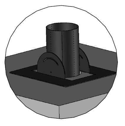
5 [Preparation Curved Fireplaces [ PRE-INSTALLATION PREPARATIONS A round fireplace can be installed with a cone or flat top. When a cone is installed, it must be installed BEFORE installation of the fireplace begins (according to the installation instructions on page 25 and depending upon the model of the selected cone. [ VENT PIPE AND CONE INSTALLATION First install the vent pipe cone (see the relevant manual for your type of cone). Thread the vent pipe inside the cone to the required length. When the installation is complete, verify that the distance between the bottom of the cone and the floor is approximately 860mm (33 3/4 ). NOTE: For all round fireplace models, the cone is must be suspended from the ceiling and NOT resting on the fireplace. [ GAS & ELECTRICITY SOURCE Provide gas and electricity according to local code. Electrical source For fireplaces with double glass and blowers, you will need to connect the unit to a 110V/220V outlet. NOTE: This manual describes the installation of the vent pipe cone and the fireplace assembly. Explanations regarding gas and vent pipe installation are described in a separate Installation & Operation Manual. 5


6 [Installation Curved Fireplaces [GRILL COVER Unpack the unit. Unscrew the 4 Phillips screws on the top of the unit. Lift the grill cover top up and away from the unit. [DECORATIVE COVERS Gently hand lift 4 peripheral decorative covers. These decorative covers are secured in position with magnetic supports. NOTE: Use a coated screwdriver only. 6


7 [Installation Curved Fireplaces [BURNER UNIT REMOVAL Carefully lift the burner unit by unscrewing 8 base plate screws, and manually lift and remove the entire burner plate upwards. [PREPARATIONS Gently and securely rotate and position the fireplace base on its side. It is recommended that you prepare a soft material to place underneath the fireplace base for protection. [GAS VALVE The gas valve is screwed to one of the 4 fireplace legs in the factory prior to shipping. Prior to attaching the legs to the fireplace, choose the best location for the gas valve and attach the leg/gas valve assembly to the unit, as described below. [FIREPLACE LEGS With the fireplace on its side, install the adjustable leg fixtures to each one of the 4 legs underneath. Make sure the leg fixtures are fitted while the adjusting screws are pointing to the fireplace center (inward direction). This is important for height adjustment later during the installation process. When complete, rotate the fireplace base to the upright position so that it stands solidly on its the legs. 7

8 [Installation Curved Fireplaces [FIREPLACE BASE INSTALLATION: Position the fireplace base centered underneath the vent pipe cone. Make sure there is gas and electrical access underneath the fireplace base. 8


9 [Installation Curved Fireplaces [LEG PLACEMENT: With the fireplace base centered under the vent pipe cone, secure the legs to the floor with anchor screws. Note: This step is important to avoid any fireplace movement during use. After securing the leg fixtures to the floor, release all adjustment screws to level the fireplace. It is recommended to use a spirit level to determine the base level in "X" and "Y" directions before tightening the height adjustment screws. NOTE: Perform the above installation process through the burner base-plate hole on top. [SAFETY GAP: Before tightening the fixture legs, make sure that there is a safety gap of 6.35mm [1/4"] between the fireplace base (skirt) to the floor. Note: THIS IS AN IMPORTANT LPG SAFETY PRECAUTION. 6.35mm [1/4"] 9

10 [Installation Curved Fireplaces [GAS AND ELECTRICAL CONNECTIONS: Install and connect the gas access valve to the supply line, and connect the gas pipe positioned between the gas valve to the burner. Connect the electrical wiring to the burner controller according to model specifications. Place the back the burner unit in position, and tighten the 8 top screws to secure the burner. NOTE: Make sure the burner is properly seated while the gas pipe and electrical wiring are correctly positioned and attached underneath. 10


11 [Installation Curved Fireplaces [GLASS TRIMS: Slightly release both flat glass panel trim screws to allow easy installation for the next steps. NOTE: Do not disassemble the glass trims. [TOP COVER: Gently release both flat glass panel trim screws on the top cover, and lift the trims by sliding them out while the screws remain in place for easy installation on the next step. [NOTES: Do not fully remove the screws. It is recommended that you perform this step while the top cover is in an inverted (upside down) position. Top Cover in Upside Down 11


12 [Installation Curved Fireplaces [TOP COVER POSITION: Make sure the top cover and base are aligned during the installation by lining up both the "V" position marks on the fireplace top and base. 12

13 [Installation Curved Fireplaces [VENT PIPE CONNECTION Once the fireplace top cover is settled on the base, thread the vent pipe segment into place. Then, connect the bottom vent pipe segment to the top cover using drill screws. 13


14 [Installation Curved Fireplaces [TOP COVER POSITIONING: Raise the top cover with the vent pipe segment up into the cone to a height that allows the central glass panels to be inserted into place. Attach the 3 or 4 support struts to symmetrically support the weight of the top cover and vent pipe. Lock the support struts in place to prevent the top cover from falling. This is accomplished using the screws in the fireplace base and the notches on the upper edge of each strut. 14

15 [Installation Curved Fireplaces [SECURING THE TOP COVER: Take note of the height indicators on the back of the top cover support struts. You will need to adjust the length of the struts to accompany the various steps of installation of the fireplace: Position 1: High Position 2: Middle Position 3: Low IMPORTANT: Make sure that you secure the top cover throughout the entire installation process to avoid collapse. For your safety, remember that the round fireplace structural integrity is achieved only when all glass panels are installed and secured in their correct position! 15


16 [Installation Curved Fireplaces [GLASS PANEL INSTALLATION: Firmly grasp the top cover from above and gently install the flat glass panel in the bottom trim while centering the glass, and tighten into position. Make sure the glass panel edges do not exceed the fireplace outer base circumference. This enables the outer-curved glass installation in the next steps. Slightly tighten the bottom trim screws to retain the glass panel in position. Repeat with the opposite flat glass panel. 16

 before continuing.")
17 [Installation Curved Fireplaces [TOP COVER POSITIONING: While holding both flat glass panels parallel and perpendicular to the base, lower and position the top cover to rest on top of the glass edges. Before lowering the top cover, adjust the height of the legs if necessary to ensure that the entire unit is level. Make sure that the legs are tightly fastened in position 2 (see above) before continuing. Make sure the glass panels are isolated using a high temperature seal. Vertically position the glass panels against the top trims fixed side. 17


18 [Installation Curved Fireplaces [FLAT GLASS PANEL INSTALLATION: While the cover is positioned on top of the flat glass, make sure that the high temperature seal is still in place, and attach the top trim to the correct position. Make sure that the glass panel edges do not exceed the outer top cover circumference. This enables the outer curved glass installation in the next steps. 18

19 [Installation Curved Fireplaces [TOP GRILL INSTALLATION: After securing the 2 internal flat glass panels and before continuing with the curved glass installation process, return the grill cover to the correct location, and secure it with the 4 Phillips screws. NOTE: Perform this step carefully to avoid damage to the glass panels. 19


20 [Installation Curved Fireplaces [CURVED GLASS PANEL INSTALLATION: Note: This installation step is important for optimal product presentation. Gently release the outer glass bracket screws to allow the easy insertion of the first curved glass panel. To enable insertion of the firsts curved glass panel, you will need to temporarily remove the support strut that is closest to the glass panel insertion point. Make sure that the front curved glass panel is centered and positioned. With the first curved glass panel in position, insert the top cover glass bracket and tighten it slightly so that it securely grasps the glass. [NOTE: Lift all top cover glass brackets before starting this step. Use only one top cover glass bracket for each glass panel until all 3 panels are in place. This allows for easier adjustments. The remaining brackets can be added later to complete the process. Position the ORTAL logo plate to point to the fireplace front. 20

.")
21 [Installation Curved Fireplaces [CURVED GLASS PANEL INSTALLATION: Install the next curved panel as in the previous step, and make sure that panel edges remain collinear and parallel after tightening the brackets. Remove a single support strut at each step to enable insertion of each curved glass panel until glass installation is complete. The glass edges must touch each other for optimal seal results. Make sure the glass edges of the next panel remains aligned and parallel after tightening the brackets. When you complete installing all 4 curved panels, ensure that all brackets are correctly positioned and secured (both on the fireplace base and the top cover). To ensure a seal between the glass panels, apply clear silicon (provided in the fireplace package) at the junction points between each panel. 21

22 [Installation Curved Fireplaces [CURVED GLASS PANEL INSTALLATION: Before completing the installation of the last curved glass panel, arrange the logs or stone decorations on top of the burner. After completing the logs or stone decorative arrangements, install the last curved glass panel to close off the fireplace. [IMPORTANT: To avoid oxygen circulation complications which may cause burner issues, place logs and decorative stones only on top of the central grill plate (and not on its side covers as marked in RED color in the image). 22
23 [Installation Curved Fireplaces [FINAL STEP: Complete the glass brackets installation and make sure that all glass brackets are securely tightened on the top cover and the fireplace base circumference. Replace the 4 peripheral decorative covers on the magnetic supports to complete the installation process. In DOUBLE GLASS fireplaces, at this point, install the remaining glass and profiles. 23
24 [Maintenance Curved & Island Fireplaces [MAINTANANCE: The following maintenance instructions are for Round & Island Fireplaces (Island 130 and Standalone 7565 Curved Tunnel) An annual maintenance procedure MUST be performed by a licensed installer! The installer must verify the working condition of the entire fireplace installation and specifically the following items: Internal Glass - Verify that the straight internal glass panels are in good shape: No chips, cracks or breaks. If there are, the affected panel must be replaced immediately. Upper Ignition Valves - Ensure that the valves are in working order and that they are closed. When the maintenance procedure is completed, verify that trims are locked in place and that the fireplace is secured in place - the roof of the fireplace should not be able to move at all. All issues must be reported to the service provider. Use the fireplace maintenance door to service the gas valve, receiver and for battery replacement (in applicable models). Perform the following steps for complex servicing (e.g., servicing the burner): 1. To access the burner, lift one of the side, curved glass panels (located perpendicular to the burner). For DG Type (double glass) fireplaces, (models equipped with both external and internal curved glass), lift panels located on the same side. 2. Use a flat-head screwdriver to remove the closest peripheral decorative cover on the fireplace base that conceals the glass bracket screws. Note: Only remove one side of the curved glass panels. 3. Slightly release the bottom glass bracket screws Note: Release only the bracket that clamps the specific glass panel that needs to be removed. 4. Gently release the upper bracket screws, and lift the specific bracket that clamps the glass panel. 5. Carefully lift the curved glass panel. 6. Remove the decorative logs or stones from the burner. 7. Lift the burner unit by releasing all eight top screws (10mm hexagonal screws). 8. Reverse Steps 7-1 to reassemble the device. 24


25 [Installation Wall Mounted Curved Fireplace [VENT PIPE ASSEMBLY Position the vent pipe cone in place according to the manufacturer s instructions. Thread the vent pipe segment into place according to the manufacturer s instructions. Prop the vent pipe segments above the fireplace using a piece of wood or metal. Fix the cone in place. Fix the vent pipe in place..2 חיל 25


26 [Installation Wall Mounted Curved Fireplace [POSITIONING THE FIREPLACE Remove the glass panels from the fireplace and slide the fireplace, without the lower base, into place under the vent pipe cone. This is achieved by first laying the fireplace on its side and then straightening it underneath the cone. Raise the fireplace and position the lower base underneath it. Slide the fireplace into place underneath the vent pipe cone. Position the lower base underneath the fireplace. 26

27 [Installation Wall Mounted Curved Fireplace [AFFIXING FIREPLACE IN PLACE The fireplace needs to be affixed to the wall. For safety purposes, the fireplace must not be hung using the holes indicated in the illustration. 27

28 [Installation Wall Mounted Curved Fireplace [VENT PIPE ASSEMBLY Remove the 5 bolts holding the small ring in the center of the top cover of the fireplace. Then remove the small ring and place it on the burner on the lower part of the fireplace. Remove the 4 bolts holding the large valve ring. Then remove the large ring and place it on top of the small ring. Remove the 5 bolts holding the small ring. Remove the 4 bolts holding the large ring. 28

29 [Installation Wall Mounted Curved Fireplace [FINISHING INSTALLATION At this point, lower the vent pipe segment from the top cover of the fireplace (threaded through the cone in an earlier step). Connect the vent pipe segment to the large ring using drill screws. Now raise the large ring with the attached vent pipe and attach it back into place with 4 screws. Re-attach the small ring into place in the top cover of the fireplace using 5 screws. Add media (e.g., logs and stones) on top of the grill as needed and complete the installation of the glass panels on the fireplace.. Attach the vent pipe to the large ring. Raise the vent pipe back into place. Add media and complete installation of glass panels. 29

30 [Installation Island Models [BEFORE YOU BEGIN THE ISLAND FIREPLACE ASSEMBLY: Wear protective gloves when handling fireplace components. Make sure that you have TWO installers present during installation or service process. Note: If you stop at any point in the installation process, make sure that any exposed parts are protected from project site debris. The gas valve and receiver must be protected during the installation/construction phase of a project. [FIRE BOX BOTTOM Lift the outer packaging, taking great care to safely place the glass panels in a position to minimize damage. Lift the top panel, and release the fire box base from the pallet. Lift the two loose C shape trims that cover the glass lower retaining strip mounting bolts. Install the gas system as per standard user manual enclosed 30


31 [Installation Island Models [INSTALLATION Secure the legs of the unit to the base and make sure that the unit is level and aligned in the correct position per the design. Install and secure the 2 temporary supporting profiles at the corners of the island. Place the lower glass retaining trims into position, and leave the bolts slightly untightened. Note: At this stage, assistance is required to hold the glass panel(s) in position. Slide the inner 2 separating glass panels carefully into the slots between the bottom and upper trims. Support the glass so that it cannot move from the vertical position. Make sure that there is an upper gasket attached to the top metal panel where the glass is located. Carefully open the 2 bolts in the center of the supporting profiles and gently place the metal top panel into position on the glasses. 31
 in the center and not between the exterior and interior short sides on either side.")
32 [Installation Island Models [INSTALLATION Fit the glass upper retaining strips into position, and finger tighten them only at this stage while it still supports the top weight panel. Install selected interior media per image. Place media (e.g., rocks, pebbles) in the center and not between the exterior and interior short sides on either side. Note: Install the proper restrictor per the venting diagram. When the 2 small glasses are located and secured, enter the 2 big glasses to position and make sure that the corners are connected to each other, and are square and vertical. Tighten all the glass retaining bolts. Note: Over-tightening could result in damage to the glass pane. Carefully lift the top panel support, and check that the top is fully supported by the glass. Clean all the glass pieces. Once cleaned, any finger marks must be removed before igniting the fireplace. Place 2 pieces of glass (two short sides) into the retaining strips, and finger tighten the bolts only. make sure that the corners are connected to each other, and are square and vertical. Enter the upper trims and fully tightened the bolts. Fit the 2 C shaped trims that cover the glass lower retaining strip mounting bolts. 32

33 [Installation Island Models [INSTALLATION Cut the flue parts as necessary, and place the canopy into position with the flue inside, as indicated by the installation clearances. Lift the canopy and join the flue joint to the fire top panel, ensuring that the joint is sealed and mechanically sound. After lowering the canopy into position, complete the flue installation, and consider access to joints and the canopy top extension fitting. Ensure that all joints are sealed and mechanically sound. Fit the fuel bed and proceed as instructed. Test the unit. 33


34 34 [Bordelet Chimney Assembly Instruction


35 [Ortal Chimney Assembly Instructions Assembly Instructions for a chimney on a sloped roof. Installation on a sloped roof Installation on a flat roof Adjust the tilt mechanism to match the slope of the roof. Attach the stabilizers to the roof beams using 4 M10 screws 35
36 [Glass Types (for double glass models) 36


37 [Log Sets and Stones [English Long Branch and English Short Branch for Burner 45 2 LONG BRANCHES and 5 SHORT BRANCHES and one Bag (Beige) [White Stones (SMALL PEBBLES) for Burner 45 4 Bags [Visit our website for additional information regarding logs and pebbles. 37

38 38 [Clearances for Circle 70 EU / 7565 Curved Tunnel
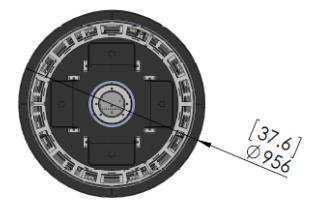
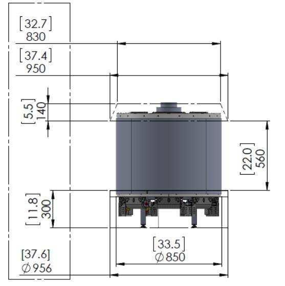
39 [Clearances for Circle 70 EU / 7565 Curved Tunnel for DG 39
YOUR LIFE. YOUR FIRE. Ortal Curved & Islands Fireplaces Installation Manual. Ortal USA - Version: 1.3 November, 2017 SKU: KPMANCIRISLUS17B
 YOUR LIFE. YOUR FIRE. Ortal Curved & Islands Fireplaces Installation Manual Ortal USA - Version: 1.3 November, 2017 SKU: KPMANCIRISLUS17B [THIS ISTALLATION MANUAL INCLUDES ASSEMBLY INSTRUCTIONS FOR THESE
Curium 19H Installation Instructions & Parts List
 Curium 19H Installation Instructions & Parts List Illustration Curium 19H Right Hand Page 1 of 15 01/07/2016 Revision 2.1 IMPORTANT This shower screen / enclosure must be installed by suitably qualified
Deauville Installation Guide
 vjul16 (for 17 or 24 mm Surface Wall Profiles) DO NOT ASSEMBLE WITHOUT FULLY READING THESE INSTRUCTIONS Page 2 Thank you for purchasing this Deauville shower enclosure. Please study these instructions
Portofino Installation Guide
 vjul16 (for 17 or 24 mm Surface Wall Profiles) DO NOT ASSEMBLE WITHOUT FULLY READING THESE INSTRUCTIONS Page 2 Thank you for purchasing this Portofino shower enclosure. Please study these instructions
EmagiKit. Privacy Pod Plus. Quiet. Easy. Affordable. INSTRUCTIONS ASSEMBLY
 EmagiKit Privacy Pod Plus Quiet. Easy. Affordable. INSTRUCTIONS ASSEMBLY DIMENSIONS AND COMPONENTS 47 47 Ceiling Unit 2-B 2-L 2-R Glass Door Corner Trim Door Handle 90 Adjustable Height Work Surface 1-B
Installation Instructions
 For Medium (15-18.5K) + Heavy duty (22-28.5K) Air Conditioner READ BEFORE INSTALLING UNIT To avoid risk of personal injury, property damage, or product damage due to the weight of this device and sharp
ASSEMBLY INSTRUCTIONS FOR SL500A AND SL500AL
 ASSEMBLY INSTRUCTIONS FOR SL500A AND SL500AL January 2013 The SL500A is a square upright glass cabinet with a single hinged lockable door. It has five adjustable shelves plus the base. It also has an optional
GE Monogram. Installation. Instructions. 36" Vent Hood. Model ZV750. Call anywhere in the US and Canada -
 at :: rangehoods. com GE Monogram Instructions Model ZV750 GE Monogram at:: rangehoods. com is a division of CAUTION WARNING Before you begin Read these instructions completely and carefully. IMPORTANT:
Kenwood Dining Table. Installation Instructions for Kenwood Dining Table KW-1242-K
 Kenwood Dining Table Installation Instructions for Kenwood Dining Table KW-1242-K 1 IMPORTANT Contents Please consult your Crystal Fire instruction manual for detailed instructions Required and important
Heavy Duty Ceiling Tilt Mount Installation Manual
 HD-CTM-5580 Heavy Duty Ceiling Tilt Mount Installation Manual *This Installation requires a minimum of two people. For your safety: Read the complete instruction manual before starting an installation
Portofino Case2 Installation Guide
 Portofino Case2 Installation Guide vjun16 (for 17 or 24 mm Surface Wall Profile) DO NOT ASSEMBLE WITHOUT FULLY READING THESE INSTRUCTIONS Page 2 Thank you for purchasing this Portofino Case 2 shower enclosure.
VYTEX PREMIUM SLIDING GLASS DOOR. Table of Contents. Precautions and Safety 2. Tools Required...3. Inspect and Prepare Door...4
 VYTEX PREMIUM SLIDING GLASS DOOR Table of Contents Precautions and Safety 2 Tools Required...3 Inspect and Prepare Door...4 Hardware and Parts Check List....4 Master Frame Assembly 5 Master Frame Installation..7
Installation Instructions
 edium + Heavy duty READ BEFORE INSTALLING UNIT Preliminary instructions: 1. Check window opening size: the mounting parts furnished with this air conditioner are made to install in a wooden sill double-hung
READ BEFORE INSTALLING UNIT INSTALLATION WARNINGS AND CAUTION
 edium + Heavy duty READ BEFORE INSTALLING UNIT INSTALLATION WARNINGS AND CAUTION Carefully read the installation manual before beginning. Pay attention to danger and safety notices. be exposed: Carefully
Curium 19.4H Installation Instructions & Parts List
 Curium 19.4H Installation Instructions & Parts List Illustration Curium 19.4H Right Hand Page 1 of 21 30/06/2016 Revision 1.0 IMPORTANT This shower screen / enclosure must be installed by suitably qualified
INOVO 4-LITE SLIDING PATIO DOOR ASSEMBLY AND INSTALLATION INSTRUCTIONS
 INOVO 4-LITE SLIDING PATIO DOOR ASSEMBLY AND INSTALLATION INSTRUCTIONS IMPORTANT: READ THE INSTRUCTIONS AND FAMILIARIZE YOURSELF WITH THE DOOR PARTS AND PIECES BEFORE BEGINNING ASSEMBLY AND INSTALLATION.
Frameless Inline Door With Return QCI5263
 INSTALLATION INSTRUCTIONS Frameless Inline Door With Return QCI5263 WALL MOUNT HINGES FRAMELESS DOOR / PANEL / RETURN PANEL QCI5263 REV. 0 Page 1 Certified 06/17/2016 Parts List with wall mount hinges
Installation Instructions
 For Medium (15-18.5K) + Heavy duty (-8.5K) Air Conditioner READ BEFORE INSTALLING UNIT To avoid risk of personal injury, property damage, or product damage due to the weight of this device and sharp edges
Installation Instructions for Vista Air Vertically Folding Walls
 Installation Instructions for Vista Air Vertically Folding Walls Use these instructions in conjunction with your shop drawings to see the specifics that are particular to the model you are installing.
Gallium 03 Installation Instructions & Parts List
 Gallium 03 Installation Instructions & Parts List Illustration Gallium 03, H1 Handle Left Hand: Open Out 04/05/2016 Revision 1.1 Page 1 of 19 IMPORTANT This shower screen / enclosure must be installed
TRUE TECHNICAL SERVICE MANUAL - ALL MODELS. DOORS/DRAWERS/LIDS
 DOORS/DRAWERS/LIDS 55 56 NOTES DOORS/DRAWERS/LIDS Swing s 73 74 NOTES INSTALLATION OF A GDM-SWING DOOR Phillips Head Screwdriver (2) - 1/8" Drift Punches (forged) Top Bracket NOTE: It may be necessary
Xenon 05 Installation Instructions & Parts List
 Xenon 05 Installation Instructions & Parts List Illustration Xenon 05, H1 Handle Left Hand: Open Out 26/05/2016 Revision 2.1 Page 1 of 19 IMPORTANT This shower screen / enclosure must be installed by suitably
GrowSpan Estate Pro I Greenhouse
 GrowSpan Estate Pro I Greenhouse Photo may show a different but similar model. 2016 Growers Supply All Rights Reserved. Reproduction is prohibited without permission. STK# DIMENSIONS 104564 11'-8" W x
Dubnium 11 Installation Instructions & Parts List
 Dubnium 11 Installation Instructions & Parts List Illustration Dubnium, H1 Handle Right Hand: Open Out Page 1 of 25 IMPORTANT This shower screen / enclosure must be installed by suitably qualified individuals.
4-lite Patio Door. Installation Instructions
 4-lite Patio Door Installation Instructions IMPORTANT: Read the instructions and familiarize yourself with the door parts and pieces before beginning assembly and installation. Note: Only the 5-0 x 6-8
Installation Instructions
 READ BEFORE INSTALLING UNIT INSTALLATION WARNINGS AND CAUTION Carefully read the installation manual before beginning. Follow each step as shown. Observe all local, state, and national electrical codes
INOVO 2-LITE SLIDING PATIO DOOR
 INOVO 2-LITE SLIDING PATIO DOOR ASSEMBLY AND INSTALLATION INSTRUCTIONS IMPORTANT: READ THE INSTRUCTIONS AND FAMILIARIZE YOURSELF WITH THE DOOR PARTS AND PIECES BEFORE BEGINNING ASSEMBLY AND INSTALLATION.
Wooden Frame Type Instruction Manual
 Wooden Frame TypeInstruction Manual Thank you for selecting our product. Before starting installation, please read this manual thoroughly to ensure correct installation. Please keep this manual at hand
Installation Instructions
 Installation Instructions 000964 Revision F Installation Instructions for PIRIT Read this manual fully prior to starting installation. Call American eating Customer ervice with any questions. What you
Whalen Furniture Mfg. Factory No. 5 Page # 1
 If you have any questions regarding assembly or if you are missing parts, do not return this item to Sam s Wholesale Club Please call our customer service number and have your instructions and parts list
Retractable Screen Installation Instructions For Vinyl and Aluminum Clad and Wood In-Swing Hinged Doors (See separate instructions for sliding doors)
") Retractable Screen Installation Instructions For Vinyl and Aluminum Clad and Wood In-Swing Hinged Doors (See separate instructions for sliding doors) IMPORTANT: Please read before you begin. Table of Contents
Retractable Screen Installation Instructions For Vinyl and Aluminum Clad and Wood In-Swing Hinged Doors (See separate instructions for sliding doors) IMPORTANT: Please read before you begin. Table of Contents
Installation Instructions
 Installation Instructions Follow these simple instructions to install your OneDayCab! IMPORTANT: Unpack and check shipment for damage. Verify color, size and parts before demolition. Installation of interiors
E N G L I S H GARDEN SHED. Assembly Instructions. Suitable for Models WITH VARYING DEPTHS
 GARDEN SHED Assembly Instructions Suitable for Models 6' Wide 8' Wide 0' Wide WITH VARYING DEPTHS GI0003 November 0 INSTALLATION ADVICE It's Not That Difficult! The construction of your shed isn't as complicated
ASSEMBLY INSTRUCTION CONTENT
 ASSEMBLY INSTRUCTION CONTENT 1. Main information...2 2. Opening 20 move type container...4 3. Assembly 20 move type container...6 1 1. MAIN INFORMATION Tools and materials for assembling are needed: 1.
FIXED SHOWER SCREEN For Wall Mount Hinges QCI5283
 FIXED SHOWER SCREEN For Wall Mount Hinges QCI5283 QCI5283 Page 1 Date Certified: 06/16/2016 Parts List with wall mount clamp ITEM NO. DESCRIPTION QTY. 1 FIXED GLASS PANEL 1 2 WALL MOUNT CLAMP 1 3 U-CHANNEL
Phone # La Jolla Doors. Block Frame Installation Manual Aluminum Frame with either Vinyl or Aluminum Panels
 Phone # 800-440-8785 www.lajolladoors.com La Jolla Doors Block Frame Installation Manual Aluminum Frame with either Vinyl or Aluminum Panels Thank you for choosing La Jolla Doors In this manual you will
Product must be installed as shown using the screws and brackets provided. Use of incorrect hardware could result in damage to the product.
 General Notes These installation instructions are intended to be comprehensive for a typical Keyeira/Presto configuration. Your configuration may differ. If you have questions contact Geiger Customer Service
Frameless Inline Door QCI5248
 INSTALLATION INSTRUCTIONS Frameless Inline Door QCI5248 FRAMELESS PANEL / DOOR / PANEL QCI5248 REV. 0 Page 1 Certified 06/16/2016 Parts List with glass to glass hinges *Quantities may vary. **Support Bar
Radon 07 Installation Instructions & Parts List
 Radon 07 Installation Instructions & Parts List Illustration Radon 07, H1 Handle Right Hand: Open Out 14/06/2016 Revision 1.1 Page 1 of 21 IMPORTANT This shower screen / enclosure must be installed by
Deauville Installation Guide
 vjul16 (for Recessed Wall Profiles) DO NOT ASSEMBLE WITHOUT FULLY READING THESE INSTRUCTIONS Page 2 Thank you for purchasing this Deauville shower enclosure. Please study these instructions carefully before
METALWORKS TARTAN PANELS General Installation Instructions
 CEILING SYSTEMS METALWORKS TARTAN PANELS General Installation Instructions 1. GENERAL 1.1. Product Description MetalWorks Tartan system is a combination of metal ceiling panels available in a range of
INSTALLATION: D1-NOTCH DRYWALL TRIM FLANGE
 T F W 604.549.979 604.549.9555 fluxwerx.com INSTALLATION: D1-NOTCH DRYWALL TRIM FLANGE fixture housing endcap kit optic kit join kit notch 2 cross section notch 4 cross section 4 4" 4-11/2" 4 /8 (111)
Aluminum Frame Type Instruction Manual
 Aluminum Frame TypeInstruction Manual Thank you for selecting our product. Before starting installation, please read this manual thoroughly to ensure correct installation. Please keep this manual at hand
INFINITE RANGE - CENTRE FOLDING DOOR
 INFINITE RANGE - CENTRE FOLDING DOOR CENTRE FOLDING DOOR ONLY ( RECESS) Please read these instructions before installing, as incorrect fitting will invalidate the guarantee-carry out each stage before
OXYGEN INSTALLATION. Revision date
 12345 1 Hardware List 12345 Flat head wood screw #9 x 7/8 long with #2 Phillips drive, silver Used to attach surfaces and end panels Hex set screw ½-13 x 2 long with 1/4 hex drive, black Used on Legs Hex
BIFOLD FUTON FRAME TRINITY ARM. Seat Rails and Slats x 1. *Note: Use 4pc of 100mm Bolts and 4pc of 60mm Bolts to attach the arms to the Stretchers.
 1A Parts in this box. 2pc with extra holes 2pc with extra holes & plastic stoppers Arms x 2 Back Rails and Slats x 1 Full Size: Slat Supports x 6 3pc are longer for the Back deck Back Side Rails x 2 Seat
a.k.a. casegoods instructions
 a.k.a. casegoods instructions a a.k.a. workwall installation IMPORTANT NOTES Failure to install product according to installation instruction will result in loss of warranty. Tools required for assembly
INSTALLATION MANUAL FORTRESS SERIES
 Guardian Security Structures TEL 1-406-212-2334 EMAIL rg@gssdoors.com WEB www.gssdoors.com FORTRESS SERIES GENERAL INSTALLATION GUIDELINES 1. The door frame is installed using 16 bolt screws 7,5 mm in
Sliding Glass Door Assembly and Installation Guide
 Sliding Glass Door Assembly and Installation Guide Index Door System Components and Hardware The following components are needed to complete the installation of your Sliding Patio Door unit. Check all
Frameless Inline Door QCI5254
 INSTALLATION INSTRUCTIONS Frameless Inline Door QCI5254 FRAMELESS DOOR / PANEL QCI5254 REV. 0 Page 1 Cer fied 06/16/2016 Parts List with wall mount hinges *Quanes may vary QCI5254 REV. 0 Page 2 Cer fied
GREENHOUSE 6'x8' ASSEMBLY INSTRUCTIONS. (Internal Dimensions) Overall Dimensions (Approx.) L 193 W 200 H cms 97.5" L 76" W 78.
 Overall Dimensions (Approx.) L 193 W 200 H cms 97.5 L 76 W 78.") ASSEMBLY INSTRUCTIONS GREENHOUSE 'x8' (Internal Dimensions) Overall Dimensions (Approx.) 7. L 9 W 00 H cms 97." L 7" W 78.8" H 0 IMPORTANT You must read these instructions carefully before you start to
ASSEMBLY INSTRUCTIONS GREENHOUSE 'x8' (Internal Dimensions) Overall Dimensions (Approx.) 7. L 9 W 00 H cms 97." L 7" W 78.8" H 0 IMPORTANT You must read these instructions carefully before you start to
Installation Instructions
 Installation Instructions Optima LED 8 Double-Sided StretchLite Perimeter Lit Graphic Display Line Voltage Connector Optima LED DS5 (Double-sided StretchLite Graphic Display) with Graphics Corner Bracket
7878 K940. Checkpoint Antenna. Kit Instructions. Issue B
 7878 K940 Checkpoint Antenna Kit Instructions Issue B Revision Record Issue Date Remarks A July 7, 2009 First issue B Nov2013 Revised the Checkpoint installation procedures for 7878 and 7874 scanners Added
Replacing the Reciprocator on the SWF Compact Series Machine (601C and 1201C)
") Follow the instructions below to replace the reciprocator in the SWF Compact series machines. The tools required can be found in the tool kit that came with the machine. Preparation 1. First, place the
Follow the instructions below to replace the reciprocator in the SWF Compact series machines. The tools required can be found in the tool kit that came with the machine. Preparation 1. First, place the
Assembly & Installation Instructions
 1 OF 6 Component Parts A Fixture Pipe (3) B Coupling (3) C Canopy Pipe (3) D Middle Canopy Can E Clutch (3) F Plastic Sleeve (3) G Side Canopy Can (2) H Set Screw (3) I Middle Crossbar J #10 Screws (4)
Therma-Tru Door Gallery Setup Instructions Swing Unit with Hardware Kit - Hardware Part # MADGSWU15 (Swing Unit) Part # MADGHKSU10 (Hardware Kit)
 Part # MADGHKSU10 (Hardware Kit)") Swing Unit with Hardware Kit - Hardware Tools Included: 4mm Allen Wrench, 6mm Allen Wrench, 8mm T-Handle Allen Wrench (1) 3/4" Drill Bit, (1) 7/32" Drill Bit and Hole Template Guide Tools Required: Phillips
Swing Unit with Hardware Kit - Hardware Tools Included: 4mm Allen Wrench, 6mm Allen Wrench, 8mm T-Handle Allen Wrench (1) 3/4" Drill Bit, (1) 7/32" Drill Bit and Hole Template Guide Tools Required: Phillips
Ruby 0-4-0T Kit Assembly Instructions
 Ruby 0-4-0T Kit Assembly Instructions Ruby Parts List PART NO.& NAME QTY PART NO.& NAME QTY SHEET 1 1 Frame 2 2 Bracket 4 3 M2 x 4 Hex Head Screw 25 4 Wheelset (without eccentrics) 1 5 Wheelset (with eccentrics)
Series 7600 Installation Instructions Aluminum Multi-Slide Door (Pocketing)
") Series 7600 Installation Instructions Aluminum Multi-Slide Door (Pocketing) Things to Know Before You Start Things to Know Before You Start Removal of Old Fenestration Products Ensure any old fenestration
Series 7600 Installation Instructions Aluminum Multi-Slide Door (Pocketing) Things to Know Before You Start Things to Know Before You Start Removal of Old Fenestration Products Ensure any old fenestration
Sliding Door Kit
 YOU MUST READ THIS DOCUMENT BEFORE YOU BEGIN TO ASSEMBLE THE DOOR KIT. Thank you for purchasing this GrowSpan door kit. When properly assembled and maintained, this product will provide years of reliable
compile system INSTALLATION GUIDE Updated January 2019
 INSTALLATION GUIDE Updated January 09 compile system Table of Contents Panels 0 Quick Connect Clips 0 Lock Clips 0 Panel Trims 0 Privacy Glass 0 Post Base Covers 04 Electrical 04 Power Distribution Harness
Monaco Installation Guide - Surface Profiles - vjun16
 1 Thank you for purchasing this Monaco shower screen. Please study these instructions carefully before assembly and installation. Checking of Parts Parts are listed at the beginning of this guide. Please
Installing your new Bevella Top. L Shaped Countertop with Joints No Finished Ends (Fits Between Four Walls)
") Installing your new Bevella Top L Shaped Countertop with Joints No Finished Ends (Fits Between Four Walls) Bevella RTI Countertops are engineered and manufactured to the highest quality standards, built
Installing your new Bevella Top L Shaped Countertop with Joints No Finished Ends (Fits Between Four Walls) Bevella RTI Countertops are engineered and manufactured to the highest quality standards, built
The wick in your heater needs replacing if, after repeated cleanings, any of the following conditions still exist:
 WICK REPLACEMENT The wick in your heater needs replacing if, after repeated cleanings, any of the following conditions still exist: Slow to light, hard movement of the wick adjuster knob, kerosene odor
VisioGlide 100 System W4F Four doors 2 fixed, 2 sliding
 Balcony Systems 2011 Visio Glide W4-F Curved Sliding Doors 4 doors: 2 fixed, and 2 sliding Installation guide 1. Insert silicone into the two bottom corners before closing the frame. 1 2. Connect top and
TABLE OF CONTENTS REQUIRED TOOLS
 TABLE OF CONTENTS SECTION SECTION TITLE PAGE NO. 1 2 3 4 5 Assembling Mounting Structure Installing Bicycle Supports Mounting Rack to Wall Adding Sections Customizing Rack Configuration REQUIRED TOOLS
3-LITE PATIO DOOR INSTALLATION INSTRUCTIONS
 3-LITE PATIO DOOR INSTALLATION INSTRUCTIONS IMPORTANT: Read the instructions and familiarize yourself with the door parts and pieces before beginning assembly and installation. TOOLS NEEDED: Tape Measure
Footprint Mobile Assembly Instructions
 Footprint Mobile Assembly Instructions 1998754 Revision -1 Complete Series Master Packet If you have any questions concerning these instructions, please call Kimball Office Customer Service. 20 Kimball
Installation Instructions For Heavy Duty (FAS Models) and Median (FAM Models) Air Conditioners
 and Median (FAM Models) Air Conditioners") Installation Instructions For Heavy Duty (FAS Models) and Median (FAM Models) Air Conditioners Please read ALL instructions before installing. Two people are recommended to install this product. If a new
Installation Instructions For Heavy Duty (FAS Models) and Median (FAM Models) Air Conditioners Please read ALL instructions before installing. Two people are recommended to install this product. If a new
Monaco Installation Guide - Surface Profiles
 v1 Page 1 Thank you for purchasing this Monaco shower screen. Please study these instructions carefully before assembly and installation and check all supplied parts immediately upon receipt. These instructions
Queen Wingback Bed King Wingback Bed
 Parts and Hardware List A. Side Rails with Attachment Hooks 2 pcs B. Foot Rail 1 pc C. Head Rail 1 pc D. Center Support Slat 1 pc E. Leg Supports 3 pcs F. Support Slats 4 pcs G. Flat Washers 8 pcs H. Lock
Privacy Wall Glass Selections - Polished Edge Slider Door
 Privacy Wall Glass Selections - Polished Edge Slider Door 3/6" HEX BIT PUTTY KNIFE #2 ACR BIT SUCTION CUP HOLDERS DOOR LEAF: Satin Tempered Clear Tempered LOCTITE 425 SIDE LIGHT ETCHED GLASS STYLES: Satin
INSTALLATION GUIDE MICROWAVE OVEN UPMC3084ST. MFL _00
 INSTALLATION GUIDE MICROWAVE OVEN UPMC3084ST MFL06208710_00 www.thesignaturekitchen.com YOUR SAFETY FIRST BEFORE YOU START Proper installation is the installer's responsibility! Proper installation by
HBS-AP ASSEMBLING INSTRUCTIONS
 ALUMINIUM PIPEWORK - ALUMINIUM PIPEWORK - ALUMINIUM PIPEWORK 97 HBS-AP ASSEMBLING INSTRUCTIONS 1. INTRODUCTION 1.1. This manual is very easy to consult and we recommend reading it before starting work,
M10 x 75mm Sockethead Cap Screws. 5mm Fender Washer (12) Included - (8) Required. #10 x 2.5" PH Wood Screws. (30) Included - (24) Required
 Included - (8) Required. #10 x 2.5 PH Wood Screws. (30) Included - (24) Required") Door System Unit - Hardware Tools Included: (2) 2mm Allen Wrenches, (2) 3mm Allen Wrenches, (2) 4mm Allen Wrenches, (2) 6mm Allen Wrenches, and (1) 8mm T-Handle Allen Wrench Tools Required: Phillips Screwdriver,
Door System Unit - Hardware Tools Included: (2) 2mm Allen Wrenches, (2) 3mm Allen Wrenches, (2) 4mm Allen Wrenches, (2) 6mm Allen Wrenches, and (1) 8mm T-Handle Allen Wrench Tools Required: Phillips Screwdriver,
TP4463. ASSeMBly INSTruCTIONS FLAT PANEL TV MOUNTING SYSTEM OPTION 1 OPTION 2 OPTION 3
 TP63 FLAT PANEL TV MOUNTING SYSTEM OPTION 1 OPTION 2 OPTION 3 Flat Panel TV Stand Stand with TV Mounting System Stand with Wall Mount ASSeMBly INSTruCTIONS for your safety, please follow these precautions:!
Sliding Door Kit
 YOU MUST READ THIS DOCUMENT BEFORE YOU BEGIN TO ASSEMBLE THE DOOR KIT. Thank you for purchasing this GrowSpan door kit. When properly assembled and maintained, this product will provide years of reliable
Sauna & Steam. Traditional Sauna Installation Instruction Manual
 Traditional Sauna Installation Instruction Manual Oceanic Ltd, Pountney Street, Wolverhampton, WV2 4HX Phone: 01902 450 550 sales@oceanic-saunas.co.uk www.oceanic-saunas.co.uk Contents 1.Introduction................................................
Assembly Instructions
 Selling Station Assembly Instructions View from above without top A B C D Rounded finished corners on A & D Square unfinished 3-sides on B & C Selling Station Components (2) 2' x 6' Side s Have a channel
Dual Arm Tilt LCD Mount
 Installation Manual model # 51324 M o u n t i n g S y s t e m s Dual Arm Tilt LCD Mount Fits Displays 13 to 32 Supports Up to 50 lbs (23 kgs) Projection from Wall from 3 to 17 Meets VESA Standards 50/75/100,
Assembly Instructions
 InTandem Table System November 20 InTandem Table System - Worksurface #4 x/" 4 wood screw power beam Tools Provided T-0 Extended Torx Driver T-25 Torx Driver Additional Tools Required Soft protective
Playground Assembly Instructions
 Before You Begin Playground Assembly Instructions Locate the playground set on firm, level ground. Assemble the playground on or close to its permanent location Two people are recommended to assemble the
INSTALLATION INSTRUCTIONS DANUBE ACRYLIC NEO ANGLE
 INSTALLATION INSTRUCTIONS DANUBE ACRYLIC NEO ANGLE March 2013 DOOR 2 Page 1 of 5 INSTALLATION INSTRUCTIONS NEO ANGLE 6MM FRAMELESS AND 4MM FRAMED SHOWER DOOR DANUBE, DELTA, SIGNATURE, OCEANIA, CASCADE
Low Headroom Rear Mount TorqueMaster
 Low Headroom Rear Mount Supplemental Instruction Insert This supplemental installation instruction is to be used as a supplement to the main Installation Instruction and Owner s Manual provided with the
Panoramic Door. Block Frame Installation Manual Aluminum top and bottom track with either aluminum or vinyl panels
 2515 Industry St. Oceanside, CA 92058 760-722-1250 www.panoramicdoors.com Panoramic Door Block Frame Installation Manual Aluminum top and bottom track with either aluminum or vinyl panels Signature Aluminum
Frameless Inline Door QCI5250
 INSTALLATION INSTRUCTIONS Frameless Inline Door QCI5250 FRAMELESS PANEL / DOOR / PANEL QCI0249 REV. 3 Page 1 Certified 10/12/12 Parts List with pivot hinges *Quantities may vary. QCI0249 REV. 3 Page 2
Series 1100 Aluminum Door Canopy
 Series 00 Aluminum Door Canopy with Support Arms It is our recommendation that you read instructions carefully prior to assembly and installation. Series 00 with Support Arms MOUNTING BAR (A) TOP TRIM
MPA-9000 Universal Ceiling Projector Mount Kit
 I N S T R U C T I O N M A N U A L Universal Ceiling Projector Mount Kit The Universal Ceiling Projector Mount provides a unique, simplified method of ceiling mounting your inverted projector. This low
End of Row Doors. Revision Number 1
 End of Row Doors Single Swing Door Café Style Doors Revision Number 1 Wright Line LLC 160 Gold Star Boulevard Worcester, MA 01606 Tel: 800-225-7348 508-852-4300 Fax: 508-365-6178 www.wrightline.com info@wrightline.com
Removing and Replacing the Y-truck
 Service Documentation Removing and Replacing the Y-truck To remove and replace the Y-truck you will need the following tools: 4mm Allen wrench 12mm stamped flat wrench #2 Phillips screwdriver (magnetic
CF9030 ASSEMBLY PROCEDURES
 VERMONT PROCEDURES Step 1: Unpack carton. Tools Required: Knife or scissors; hammer; Philips or Robertson screwdriver Castings Box #5 Box #4 Box #1 Box #3 Box #2 Use the knife or scissors to cut the strapping
Work Space Set-up. Slats will level the pipe during bending and help minimize twisting of the bow.
 Work Space Set-up Affix pipe bender to end of working surface Slats will level the pipe during bending and help minimize twisting of the bow. Make the slat height equal the distance from your work surface
6' Wide Premium Greenhouse Benches
 6' Wide Premium Greenhouse Benches Premium Greenhouse Bench with Stationary Top 2015 FarmTek All Rights Reserved. Reproduction is prohibited without permission. STK# DIMENSIONS 112416S6X08 6' W x 3' H
Showpiece Cabinet Integrated Stand For 32" - 52" LCD HDTV
 Showpiece Cabinet Integrated Stand For 32" - 52" LCD HDTV Installation and Assembly Instructions 2009 Incredible Technologies Inc. Version 0109 Showpiece Cabinet Integrated Stand for 32" - 52" LCD HDTV
INFINITE RANGE - HINGE DOOR
 INFINITE RANGE - HINGE DOOR HINGE DOOR + 1 SIDE RETURN PANEL (CORNER) Please read these instructions before installing, as incorrect fitting will invalidate the guarantee-carry out each stage before moving
3. Remove the flue collar by backing out the two Phillips round head machine screws.
 SERVICE MANUAL SERVICE PROCEDURES Defiant Non-Catalytic Model 1610 Woodstove **Wear gloves, a dust mask and protective eyewear when servicing a stove. ** Replacing the Fountain Assembly 1. Remove the doors,
The Useless Machine. DIY Soldering Edition. Instruction Guide v0004
 The Useless Machine DIY Soldering Edition Instruction Guide v0004 TM For the best outcome, follow each step in order. We recommend reading this guide entirely before you get started. Tools required: Soldering
Series 1500 Aluminum Door Canopy
 Series 500 Aluminum Door Canopy with Sidewings It is our recommendation that you read instructions carefully prior to assembly and installation. Series 500 with Sidewings mounting bar (A) top trim (B)
Fold-A-Way Patio Door ASSEMBLY & INSTALLATION GUIDE
 Fold-A-Way Patio Door ASSEMBLY & INSTALLATION GUIDE This instruction guide provides the minimum recommended procedures to correctly prepare the rough opening, install a fold-a-way patio door unit and apply
Video Wall Installation Instructions 2W X 3H, 3W X 3H
 Video Wall Installation Instructions 2W X 3H, 3W X 3H www.microndisplaysolutions.com Table of Contents Important Safety Instructions... 3 Configuration... 4 Package Contents, included and optional items...
B A T H R O O M G L A S S
 mistley B A T H R O O M G L A S S vaug16 Page 2 Thank you for purchasing this Trinity shower screen. Please study these instructions carefully before assembly and installation and check all supplied parts