YOUR LIFE. YOUR FIRE. Ortal Curved & Islands Fireplaces Installation Manual. Ortal USA - Version: 1.3 November, 2017 SKU: KPMANCIRISLUS17B
|
|
|
- Colin Bridges
- 5 years ago
- Views:
Transcription

1 YOUR LIFE. YOUR FIRE. Ortal Curved & Islands Fireplaces Installation Manual Ortal USA - Version: 1.3 November, 2017 SKU: KPMANCIRISLUS17B
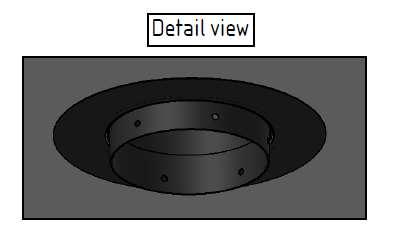
2 [THIS ISTALLATION MANUAL INCLUDES ASSEMBLY INSTRUCTIONS FOR THESE MODELS: STAND ALONE 7565 CURVED TUNNEL DOUBLE GLASS STAND ALONE 7565 CURVED DOUBLE GLASS ISLAND 130 DOUBLE GLASS WARNING Installation must be performed by a professional who is licensed to install fireplaces in the state where the installation will take place. WARNING Instructions provided by the manufacturer, ORTAL, should be considered installation recommendations. If there is any divergence between the a ufacturer s i structions and the local code, priority must be given to the local code. WARNING When the design includes hanging a hood from the ceiling, the plan must be approved by a Structural engineer. WARNING Installation of the chimney must be supervised by a constructor engineer. 1
3 [Table of Contents Preparation Curved Fireplaces... 3 Installation Curved Fireplaces... 4 Maintenance Curved & Island Fireplaces Installation Wall Mounted Curved Fireplaces Installation Island Models J.C. Bordelet hood Assembly Instruction Glass Types Clearances for 7565 Curved Tunnel DG J.C.Bordelet Hood Clearances for 7565 Curved Tunnel DG Self Top Cover
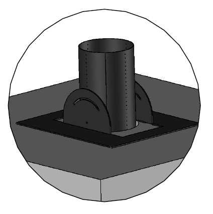
4 [Preparation Curved Fireplaces [ PRE-INSTALLATION PREPARATIONS A round fireplace can be installed with a cone or flat top. When a cone is installed, it must be installed BEFORE installation of the fireplace begins (according to the installation instructions on page 25 and depending upon the model of the selected cone. [ VENT PIPE AND CONE INSTALLATION First install the cone (see the relevant cone instructions on page 32). Thread the vent pipe inside the cone to the required length. When the installation is complete, verify that the distance between the bottom of the cone and the floor is approximately 860mm (33 3/4 ). NOTE: For all round fireplace models, the cone is must be suspended from the ceiling and NOT resting on the fireplace. [ GAS & ELECTRICITY SOURCE Provide gas and electricity at the fireplace base s center and according to local code. Electrical source For fireplaces with double glass and blowers, you will need to connect the unit to a 110V outlet. NOTE: This manual describes the installation of the vent pipe cone and the fireplace assembly. Explanations regarding gas and vent pipe installation are described in a separate Installation & Operation Manual. Positions for gas and electricity source 3

5 [Installation Curved Fireplaces [GRILL COVER Unpack the unit. Remove the grill by unscrewing the 4 Phillips screws connecting it to the firebox. Lift the grill cover tops up and away from the unit. [DECORATIVE COVERS Gently outer 4 peripheral decorative covers. These decorative covers are secured in position with magnetic supports. NOTE: Use a coated screwdriver only. 4


6 [Installation Curved Fireplaces [BURNER UNIT REMOVAL Carefully lift the burner unit by unscrewing 8 base plate screws, and manually lift and remove the entire burner plate upwards. [PREPARATIONS Gently and securely rotate and position the fireplace base on its side. It is recommended that you prepare a soft material to place underneath the fireplace base for protection. [GAS VALVE The gas valve is screwed to one of the 4 fireplace legs in the factory prior to shipping. Prior to attaching the legs to the fireplace, choose the best location for the gas valve and attach the leg/gas valve assembly to the unit, as described below. [FIREPLACE LEGS With the fireplace on its side, install the adjustable leg fixtures to each of the metal legs. Make sure the leg fixtures are fitted while the adjusting screws are pointing to the fireplace center (inward direction). This is important for height adjustment later during the installation process. When complete, rotate the fireplace base to the upright position so that it stands solidly on it s the legs. metal legs Leg Fixture 5

7 [Installation Curved Fireplaces [FIREPLACE BASE INSTALLATION: Position the fireplace base centered underneath the vent pipe cone. Make sure there is gas and electrical access underneath the fireplace base. 6


8 [Installation Curved Fireplaces [LEG PLACEMENT: With the fireplace base centered under the vent pipe cone, secure the legs to the floor with anchor screws. Note: This step is important to avoid any fireplace movement during use. After securing the leg fixtures to the floor, release all adjustment screws to level the fireplace. It is recommended to use a level to determine the base level in "X" and "Y" directions before tightening the height adjustment screws. NOTE: Perform the above installation process through the burner base-plate hole on top. [SAFETY GAP: Before tightening the fixture legs, make sure that there is a safety gap of 6.35mm [1/4"] between the fireplace base (skirt) to the floor. Note: This is an important safety precaution. 7


9 [Installation Curved Fireplaces [GAS AND ELECTRICAL CONNECTIONS: Install and connect the gas valve to the supply line, and connect the gas pipe positioned between the gas valve to the burner. Connect the electrical wiring to the burner controller per local codes. Place the back the burner unit in position, and tighten the 8 top screws to secure the burner. NOTE: Make sure the burner is properly seated while the gas pipe and electrical wiring are correctly positioned and attached underneath. 8


10 [Installation Curved Fireplaces [GLASS TRIMS: Slightly release both flat glass panel trim screws to allow easy installation for the next steps. NOTE: Do not disassemble the glass trims. [TOP COVER: Gently release both flat glass panel trim screws on the top cover, and lift the trims by sliding them out while the screws remain in place for easy installation on the next step. [NOTES: Do not fully remove the screws. It is recommended that you perform this step while the top cover is in an inverted (upside down) position. Top Cover in Upside Down view 9

11 [Installation Curved Fireplaces [TOP COVER POSITION: Make sure the top cover and base are aligned during the installation by lining up both the "V" position marks on the fireplace top and base. 10

12 [Installation Curved Fireplaces [VENT PIPE CONNECTION Once the fireplace top cover is settled on the base, thread the vent pipe segment into place. Then, connect the bottom vent pipe segment to the top cover using drill self-tapping screws. 11

 to symmetrically support the")

13 [Installation Curved Fireplaces [TOP COVER POSITIONING: Raise the top cover with the vent pipe segment up into the cone to a height that allows the central inner glass panels to be inserted into place. Attach the 3 or 4 support struts in position 1 (see page 13) to symmetrically support the weight of the top cover and vent pipe. Lock the support struts in place to prevent the top cover from falling. This is accomplished using the screws in the fireplace base and the notches on the upper edge of each strut. Step 1 Step 2 Step 3 12

14 [Installation Curved Fireplaces [SECURING THE TOP COVER: Take note of the height indicators on the back of the top cover support struts. You will need to adjust the length of the struts to accompany the various steps of installation of the fireplace: Position 1: High Position 2: Middle Position 3: Low IMPORTANT: Make sure that you secure the top cover throughout the entire installation process to avoid collapse. For your safety, remember that the round fireplace structural integrity is achieved only when all glass panels are installed and secured in their correct position! Position 3 Position 2 Position 1 13

15 [Installation Curved Fireplaces [GLASS PANEL INSTALLATION: Firmly grasp the top cover from above and gently install the flat glass panel in the bottom trim while centering the glass, and tighten into position. Make sure the glass panel edges do not exceed the fireplace outer base circumference. This enables the outer-curved glass installation in the next steps. Slightly tighten the bottom trim screws to retain the glass panel in position. Repeat with the opposite flat glass panel. 14

16 [Installation Curved Fireplaces [TOP COVER POSITIONING: While holding both flat glass panels parallel and perpendicular to the base, lower and position the top cover to rest on top of the glass edges. Before lowering the top cover, adjust the height of the legs if necessary to ensure that the entire unit is level. Make sure that the legs are tightly fastened in position 2 (see page 13) before continuing. Make sure the glass panels are isolated using a high temperature seal (gasket) and they are all in place. Vertically position the glass panels against the top trims fixed side. 15

17 [Installation Curved Fireplaces [FLAT GLASS PANEL INSTALLATION: While the cover is positioned on top of the flat glass, make sure that the gasket is still in place, and attach the top trim to the correct position. Make sure that the glass panel edges do not exceed the outer top cover circumference. This enables the outer curved glass installation in the next steps. 16


18 [Installation Curved Fireplaces [TOP GRILL INSTALLATION: After securing the 2 internal flat glass panels and before continuing with the curved glass installation process, return the grill cover to the correct location, and secure it with the 4 Phillips screws. NOTE: Perform this step carefully to avoid damage to the glass panels. 17

. Make sure that the front curved glass panel is centered and positioned.")
19 [Installation Curved Fireplaces [CURVED GLASS PANEL INSTALLATION: Note: This installation step is important for optimal product presentation. Gently release the outer glass bracket screws to allow the easy insertion of the first curved glass panel. To enable insertion of the firsts curved glass panel, you will need to remove one of the support strut that is closest to the glass panel insertion point (change the support strut to position 3 prior to removal). Make sure that the front curved glass panel is centered and positioned. With the first curved glass panel in position, insert the top cover glass bracket and tighten it slightly so that it securely grasps the glass. Note: Lift all top cover glass brackets before starting this step. Use only one top cover glass bracket for each glass panel until all 3 panels are in place. This allows for easier adjustments. The remaining brackets can be added later to complete the process. Position the ORTAL logo plate to point to the fireplace front. 18

20 [Installation Curved Fireplaces [CURVED GLASS PANEL INSTALLATION: Install the next curved panel as in the previous step, and make sure that panel edges remain collinear and parallel after tightening the brackets. Remove a single support strut at each step to enable insertion of each curved glass panel until glass installation is complete. The glass edges must touch each other for optimal seal results. Make sure the glass edges of the next panel remain aligned and parallel after tightening the brackets. When you complete installing all 4 curved panels, ensure that all brackets are correctly positioned and secured (both on the fireplace base and the top cover). The glass comes with a silicon seal on it. Make sure it is intact and does not need to be repaired. 19

21 [Installation Curved Fireplaces [CURVED GLASS PANEL INSTALLATION: Before completing the installation of the last curved glass panel, arrange the logs or stone decorations on top of the burner. After completing the logs or stone decorative arrangements, install the last curved glass panel to close off the fireplace. [IMPORTANT: To avoid oxygen circulation complications which may cause burner issues, place logs and decorative stones only on top of the central grill plate (and not on its side covers as marked in RED color in the image). 20
22 [Installation Curved Fireplaces [FINAL STEP: Complete the glass brackets installation and make sure that all glass brackets are securely tightened on the top cover and the fireplace base circumference. Replace the 4 peripheral decorative covers on the magnetic supports to complete the installation process. Install the remaining glass and profiles. 21

23 [Maintenance Curved & Island Fireplaces [MAINTANANCE: The following maintenance instructions are for Round & Island Fireplaces (Island 130 and Standalone 7565 Curved Tunnel) An annual maintenance procedure MUST be performed by a qualified installer! The installer must verify the working condition of the entire fireplace installation and specifically the following items: Internal Glass - Verify that the straight internal glass panels are in good shape: No chips, cracks or breaks. If there are, the affected panel must be replaced immediately. Upper Ignition Valves - Ensure that the valves are in working order and that they are closed. When the maintenance procedure is completed, verify that trims are locked in place and that the fireplace is secured in place - the roof of the fireplace should not be able to move at all. All issues must be reported to the service provider. Use the fireplace maintenance door to service the gas valve, receiver and for battery replacement (in applicable models). Perform the following steps for complex servicing (e.g., servicing the burner): 1. To access the burner, lift panels located on the same side. Note: glass supports the top of the fireplace do not remove more than one side at a time or it will collapse. 2. Use a flat-head screwdriver to remove the closest peripheral decorative cover on the fireplace base that conceals the glass bracket screws. Note: Only remove one side of the curved glass panels. 3. Slightly release the bottom glass bracket screws Note: Release only the bracket that clamps the specific glass panel that needs to be removed. 4. Gently release the upper bracket screws, and lift the specific bracket that clamps the glass panel. 5. Carefully lift the curved glass panel. 6. Remove the decorative logs or stones from the burner. 7. Lift the burner unit by releasing all eight top screws (10mm hexagonal screws). 8. Reverse Steps 7-1 to reassemble the device. 22


24 [Installation Wall Mounted Curved Fireplace [VENT PIPE ASSEMBLY Position the vent pipe cone in place according to the manufacturer s instructions. Thread the vent pipe segment into place according to the manufacturer s instructions. Prop the vent pipe segments above the fireplace using a piece of wood or metal. Fix the cone in place according to the specific J.C. Bordelet cone instructions..2 חיל 23


25 [Installation Wall Mounted Curved Fireplace [POSITIONING THE FIREPLACE Remove the glass panels from the fireplace and slide the fireplace, without the lower base, into place under the vent pipe cone. This is achieved by first laying the fireplace on its side and then straightening it underneath the cone. Raise the fireplace and position the lower base underneath it. Slide the fireplace into place underneath the vent pipe cone. Position the lower base underneath the fireplace. 24

26 [Installation Wall Mounted Curved Fireplace [AFFIXING FIREPLACE IN PLACE After the fireplace is in the right position on the ground, use the holes indicated to affix it to the wall. In case you want to hang the fireplace on the wall, use the standard Ortal hanging bracket. CAUTION: do not use the indicated holes for hanging. 25

27 [Installation Wall Mounted Curved Fireplace [VENT PIPE ASSEMBLY Remove the 5 bolts holding the small ring in the center of the top cover of the fireplace. Then remove the small ring and place it on the burner on the lower part of the fireplace. Remove the 4 bolts holding the large valve ring. Then remove the large ring and place it on top of the small ring. Remove the 5 bolts holding the small ring. Remove the 4 bolts holding the large ring. 26

28 [Installation Wall Mounted Curved Fireplace [FINISHING INSTALLATION At this point, lower the vent pipe segment from the top cover of the fireplace (threaded through the cone in an earlier step). Connect the vent pipe segment to the large ring using drill screws. Now raise the large ring with the attached vent pipe and attach it back into place with 4 screws. Re-attach the small ring into place in the top cover of the fireplace using 5 screws. Add media (e.g., logs and stones) on top of the grill as needed and complete the installation of the glass panels on the fireplace.. Attach the vent pipe to the large ring. Raise the vent pipe back into place. Add media and complete installation of glass panels. 27

29 [Installation Island Models [BEFORE YOU BEGIN THE ISLAND FIREPLACE ASSEMBLY: Make sure that you have TWO installers present during installation or service process. Note: If you stop at any point in the installation process, make sure that any exposed parts are protected from project site debris. The gas valve and receiver must be protected during the installation/construction phase of a project. Note: In case the unit has a hood, please start with the Installation steps on page 31. [FIRE BOX BOTTOM Lift the outer packaging, taking great care to safely place the glass panels in a position to minimize damage. Lift the top panel, and release the fire box base from the pallet. Lift the two loose C shape trims that cover the glass lower retaining strip mounting bolts. Install the gas system as per standard user manual enclose 28


30 [Installation Island Models [INSTALLATION Secure the legs of the unit to the base and make sure that the unit is level and aligned in the correct position per the design. Install and secure the 2 temporary supporting profiles for both corners of the island. Note: make sure that the supporting profiles are in the maximum height mode. Place the lower glass retaining trims into position, and leave the bolts slightly loose. Note: At this stage, assistance is required to hold the glass panel(s) in position. Slide the inner 2 separating glass panels carefully into the slots between the bottom and upper trims. Support the glass so that it cannot move from the vertical position. Make sure that there is an upper gasket attached to the top metal panel where the glass is located. Carefully remove the two support brackets and lower the top onto the glass 29

31 [Installation Island Models [INSTALLATION Fit the glass upper retaining strips into position, and finger tighten them only at this stage while it still supports the top weight panel. When the 2 small glasses are located and secured, enter the 2 big glasses to position and make sure that the corners are connected to each other, and are square and vertical. Tighten all the glass retaining bolts. Note: Over-tightening could result in damage to the glass pane. Carefully lift the top panel support, and check that the top is fully supported by the glass. Clean all the glass pieces. Once cleaned, any finger marks must be removed before igniting the fireplace. Place 2 pieces of glass (two short sides) into the retaining strips, and finger tighten the bolts only. make sure that the corners are connected to each other, and are square and vertical. Enter the upper trims and fully tightened the bolts. Fit the 2 C shaped trims that cover the glass lower retaining strip mounting bolts. CAUTION: never remove glass for more than one side. 30


32 [Installation Island Models [INSTALLATION Assemble the flue parts as necessary, and place the canopy into position with the flue inside, as indicated by the installation clearances. Lift the canopy and connect the flue to the fire top panel, ensuring that the joint is sealed and mechanically sound. After lowering the canopy into position, complete the flue installation, and consider access to joints and the canopy top extension fitting. Following these steps please place the fireplace in its position as per page Ensure that all joints are sealed and mechanically sound. Install selected interior media per image. Place media (e.g., logs, pebbles) in the center and not between the exterior and interior short sides on either side. Please see ORTAL Installation manual. Hanging detail 31

33 [Installation Island Models Note: Install the proper restrictor per the venting diagram. 32

34 [BORDELET Chimney 33
35 INNER GLASS OUTER GLASS 34
36 [Clearances for 7565 Curved Tunnel DG Self Top Cover 35
37 36
YOUR LIFE. YOUR FIRE. Ortal Curved & Islands Fireplaces User s Manual
 YOUR LIFE. YOUR FIRE. Ortal Curved & Islands Fireplaces User s Manual [USA Fireplace Models [THIS ISTALLATION MANUAL INCLUDES ASSEMBLY INSTRUCTIONS FOR THESE MODELS: STAND ALONE 7565 CURVED TUNNEL DOUBLE
Installation Instructions
 For Medium (15-18.5K) + Heavy duty (22-28.5K) Air Conditioner READ BEFORE INSTALLING UNIT To avoid risk of personal injury, property damage, or product damage due to the weight of this device and sharp
Curium 19H Installation Instructions & Parts List
 Curium 19H Installation Instructions & Parts List Illustration Curium 19H Right Hand Page 1 of 15 01/07/2016 Revision 2.1 IMPORTANT This shower screen / enclosure must be installed by suitably qualified
Installation Instructions
 Installation Instructions Optima LED 8 Double-Sided StretchLite Perimeter Lit Graphic Display Line Voltage Connector Optima LED DS5 (Double-sided StretchLite Graphic Display) with Graphics Corner Bracket
TRUE TECHNICAL SERVICE MANUAL - ALL MODELS. DOORS/DRAWERS/LIDS
 DOORS/DRAWERS/LIDS 55 56 NOTES DOORS/DRAWERS/LIDS Swing s 73 74 NOTES INSTALLATION OF A GDM-SWING DOOR Phillips Head Screwdriver (2) - 1/8" Drift Punches (forged) Top Bracket NOTE: It may be necessary
Kenwood Dining Table. Installation Instructions for Kenwood Dining Table KW-1242-K
 Kenwood Dining Table Installation Instructions for Kenwood Dining Table KW-1242-K 1 IMPORTANT Contents Please consult your Crystal Fire instruction manual for detailed instructions Required and important
Deauville Installation Guide
 vjul16 (for 17 or 24 mm Surface Wall Profiles) DO NOT ASSEMBLE WITHOUT FULLY READING THESE INSTRUCTIONS Page 2 Thank you for purchasing this Deauville shower enclosure. Please study these instructions
Installation Instructions
 edium + Heavy duty READ BEFORE INSTALLING UNIT Preliminary instructions: 1. Check window opening size: the mounting parts furnished with this air conditioner are made to install in a wooden sill double-hung
READ BEFORE INSTALLING UNIT INSTALLATION WARNINGS AND CAUTION
 edium + Heavy duty READ BEFORE INSTALLING UNIT INSTALLATION WARNINGS AND CAUTION Carefully read the installation manual before beginning. Pay attention to danger and safety notices. be exposed: Carefully
Portofino Installation Guide
 vjul16 (for 17 or 24 mm Surface Wall Profiles) DO NOT ASSEMBLE WITHOUT FULLY READING THESE INSTRUCTIONS Page 2 Thank you for purchasing this Portofino shower enclosure. Please study these instructions
GE Monogram. Installation. Instructions. 36" Vent Hood. Model ZV750. Call anywhere in the US and Canada -
 at :: rangehoods. com GE Monogram Instructions Model ZV750 GE Monogram at:: rangehoods. com is a division of CAUTION WARNING Before you begin Read these instructions completely and carefully. IMPORTANT:
Frameless Inline Door With Return QCI5263
 INSTALLATION INSTRUCTIONS Frameless Inline Door With Return QCI5263 WALL MOUNT HINGES FRAMELESS DOOR / PANEL / RETURN PANEL QCI5263 REV. 0 Page 1 Certified 06/17/2016 Parts List with wall mount hinges
INSTALLATION: D1-NOTCH DRYWALL TRIM FLANGE
 T F W 604.549.979 604.549.9555 fluxwerx.com INSTALLATION: D1-NOTCH DRYWALL TRIM FLANGE fixture housing endcap kit optic kit join kit notch 2 cross section notch 4 cross section 4 4" 4-11/2" 4 /8 (111)
EmagiKit. Privacy Pod Plus. Quiet. Easy. Affordable. INSTRUCTIONS ASSEMBLY
 EmagiKit Privacy Pod Plus Quiet. Easy. Affordable. INSTRUCTIONS ASSEMBLY DIMENSIONS AND COMPONENTS 47 47 Ceiling Unit 2-B 2-L 2-R Glass Door Corner Trim Door Handle 90 Adjustable Height Work Surface 1-B
Gallium 03 Installation Instructions & Parts List
 Gallium 03 Installation Instructions & Parts List Illustration Gallium 03, H1 Handle Left Hand: Open Out 04/05/2016 Revision 1.1 Page 1 of 19 IMPORTANT This shower screen / enclosure must be installed
Phone # La Jolla Doors. Block Frame Installation Manual Aluminum Frame with either Vinyl or Aluminum Panels
 Phone # 800-440-8785 www.lajolladoors.com La Jolla Doors Block Frame Installation Manual Aluminum Frame with either Vinyl or Aluminum Panels Thank you for choosing La Jolla Doors In this manual you will
Xenon 05 Installation Instructions & Parts List
 Xenon 05 Installation Instructions & Parts List Illustration Xenon 05, H1 Handle Left Hand: Open Out 26/05/2016 Revision 2.1 Page 1 of 19 IMPORTANT This shower screen / enclosure must be installed by suitably
Dubnium 11 Installation Instructions & Parts List
 Dubnium 11 Installation Instructions & Parts List Illustration Dubnium, H1 Handle Right Hand: Open Out Page 1 of 25 IMPORTANT This shower screen / enclosure must be installed by suitably qualified individuals.
VYTEX PREMIUM SLIDING GLASS DOOR. Table of Contents. Precautions and Safety 2. Tools Required...3. Inspect and Prepare Door...4
 VYTEX PREMIUM SLIDING GLASS DOOR Table of Contents Precautions and Safety 2 Tools Required...3 Inspect and Prepare Door...4 Hardware and Parts Check List....4 Master Frame Assembly 5 Master Frame Installation..7
Aluminum Frame Type Instruction Manual
 Aluminum Frame TypeInstruction Manual Thank you for selecting our product. Before starting installation, please read this manual thoroughly to ensure correct installation. Please keep this manual at hand
ASSEMBLY INSTRUCTIONS FOR SL500A AND SL500AL
 ASSEMBLY INSTRUCTIONS FOR SL500A AND SL500AL January 2013 The SL500A is a square upright glass cabinet with a single hinged lockable door. It has five adjustable shelves plus the base. It also has an optional
Curium 19.4H Installation Instructions & Parts List
 Curium 19.4H Installation Instructions & Parts List Illustration Curium 19.4H Right Hand Page 1 of 21 30/06/2016 Revision 1.0 IMPORTANT This shower screen / enclosure must be installed by suitably qualified
Studio Face Xtreme 6020 Installation Instructions (Nickel , Black )
") Packing List Face Trim (4 Pieces) (3) Hanging Brackets (9) 3/16 x 1-1/4 Masonry Screws 9/64 Drill Bit Compatibility (2) Lower Brackets w Magnets (2) Lower Facing Plates (4) 2 Drywall Screws Trim Hardware
Packing List Face Trim (4 Pieces) (3) Hanging Brackets (9) 3/16 x 1-1/4 Masonry Screws 9/64 Drill Bit Compatibility (2) Lower Brackets w Magnets (2) Lower Facing Plates (4) 2 Drywall Screws Trim Hardware
4-lite Patio Door. Installation Instructions
 4-lite Patio Door Installation Instructions IMPORTANT: Read the instructions and familiarize yourself with the door parts and pieces before beginning assembly and installation. Note: Only the 5-0 x 6-8
Series 1100 Aluminum Door Canopy
 Series 00 Aluminum Door Canopy with Support Arms It is our recommendation that you read instructions carefully prior to assembly and installation. Series 00 with Support Arms MOUNTING BAR (A) TOP TRIM
Wooden Frame Type Instruction Manual
 Wooden Frame TypeInstruction Manual Thank you for selecting our product. Before starting installation, please read this manual thoroughly to ensure correct installation. Please keep this manual at hand
Portofino Case2 Installation Guide
 Portofino Case2 Installation Guide vjun16 (for 17 or 24 mm Surface Wall Profile) DO NOT ASSEMBLE WITHOUT FULLY READING THESE INSTRUCTIONS Page 2 Thank you for purchasing this Portofino Case 2 shower enclosure.
a.k.a. casegoods instructions
 a.k.a. casegoods instructions a a.k.a. workwall installation IMPORTANT NOTES Failure to install product according to installation instruction will result in loss of warranty. Tools required for assembly
7878 K940. Checkpoint Antenna. Kit Instructions. Issue B
 7878 K940 Checkpoint Antenna Kit Instructions Issue B Revision Record Issue Date Remarks A July 7, 2009 First issue B Nov2013 Revised the Checkpoint installation procedures for 7878 and 7874 scanners Added
INOVO 2-LITE SLIDING PATIO DOOR
 INOVO 2-LITE SLIDING PATIO DOOR ASSEMBLY AND INSTALLATION INSTRUCTIONS IMPORTANT: READ THE INSTRUCTIONS AND FAMILIARIZE YOURSELF WITH THE DOOR PARTS AND PIECES BEFORE BEGINNING ASSEMBLY AND INSTALLATION.
864 Double-Door Face. Compatibility: 864 TRV GS 864 HO. Packing List: Installation Details. Used on All Fireplaces
 Compatibility: 864 TRV GS 864 HO Packing List: 864 ST Used on All Fireplaces Doors Faceplate Baffle Hinge Pins Magnets (shipped on doors) Faceplate #8 x 3/8 Sheet Metal Screws Upper and Lower Grills Installation
INOVO 4-LITE SLIDING PATIO DOOR ASSEMBLY AND INSTALLATION INSTRUCTIONS
 INOVO 4-LITE SLIDING PATIO DOOR ASSEMBLY AND INSTALLATION INSTRUCTIONS IMPORTANT: READ THE INSTRUCTIONS AND FAMILIARIZE YOURSELF WITH THE DOOR PARTS AND PIECES BEFORE BEGINNING ASSEMBLY AND INSTALLATION.
Series 1500 Aluminum Door Canopy
 Series 500 Aluminum Door Canopy with Sidewings It is our recommendation that you read instructions carefully prior to assembly and installation. Series 500 with Sidewings mounting bar (A) top trim (B)
Assembly & Installation Instructions
 1 OF 6 Component Parts A Fixture Pipe (3) B Coupling (3) C Canopy Pipe (3) D Middle Canopy Can E Clutch (3) F Plastic Sleeve (3) G Side Canopy Can (2) H Set Screw (3) I Middle Crossbar J #10 Screws (4)
Sliding Door Kit
 YOU MUST READ THIS DOCUMENT BEFORE YOU BEGIN TO ASSEMBLE THE DOOR KIT. Thank you for purchasing this GrowSpan door kit. When properly assembled and maintained, this product will provide years of reliable
BIFOLD FUTON FRAME TRINITY ARM. Seat Rails and Slats x 1. *Note: Use 4pc of 100mm Bolts and 4pc of 60mm Bolts to attach the arms to the Stretchers.
 1A Parts in this box. 2pc with extra holes 2pc with extra holes & plastic stoppers Arms x 2 Back Rails and Slats x 1 Full Size: Slat Supports x 6 3pc are longer for the Back deck Back Side Rails x 2 Seat
ASSEMBLY INSTRUCTIONS
 SKU # 693964 Model #WSFP46ECHD-8 ASSEMBLY INSTRUCTIONS Grafton 46 inch Media Console Infrared Electric Fireplace in Medium Brown Finish Questions, problems, missing parts? Before returning to the store,
Installation Instructions
 Installation Instructions 000964 Revision F Installation Instructions for PIRIT Read this manual fully prior to starting installation. Call American eating Customer ervice with any questions. What you
Footprint Mobile Assembly Instructions
 Footprint Mobile Assembly Instructions 1998754 Revision -1 Complete Series Master Packet If you have any questions concerning these instructions, please call Kimball Office Customer Service. 20 Kimball
Installing your new Bevella Top. L Shaped Countertop with Joints No Finished Ends (Fits Between Four Walls)
") Installing your new Bevella Top L Shaped Countertop with Joints No Finished Ends (Fits Between Four Walls) Bevella RTI Countertops are engineered and manufactured to the highest quality standards, built
Installing your new Bevella Top L Shaped Countertop with Joints No Finished Ends (Fits Between Four Walls) Bevella RTI Countertops are engineered and manufactured to the highest quality standards, built
Low Headroom Rear Mount TorqueMaster
 Low Headroom Rear Mount Supplemental Instruction Insert This supplemental installation instruction is to be used as a supplement to the main Installation Instruction and Owner s Manual provided with the
OXYGEN INSTALLATION. Revision date
 12345 1 Hardware List 12345 Flat head wood screw #9 x 7/8 long with #2 Phillips drive, silver Used to attach surfaces and end panels Hex set screw ½-13 x 2 long with 1/4 hex drive, black Used on Legs Hex
Mount to the Wall INSTALLATION MANUAL
 Mount to the Wall 15 Locate the Wooden Studs This step applies to wooden stud wall installation only. Determine and mark the exact locations of two stud centers on the wall. Wooden studs should be spaced
Assembly Instructions 10 X 10 Aluminum Roof Support
 Assembly Instructions 10 X 10 Aluminum Roof Support Aluminum Roof Support Bolt Package 16-5/16 X 2 ¼ SS Bolt 24-5/16 X 1 SS Bolt 40-5/16 SS Nylon Lock Nuts 16-5/16 SS Flat Washers 28-4 ½ Wood Screws 36-1
Frameless Inline Door QCI5254
 INSTALLATION INSTRUCTIONS Frameless Inline Door QCI5254 FRAMELESS DOOR / PANEL QCI5254 REV. 0 Page 1 Cer fied 06/16/2016 Parts List with wall mount hinges *Quanes may vary QCI5254 REV. 0 Page 2 Cer fied
Installation Instructions for Vista Air Vertically Folding Walls
 Installation Instructions for Vista Air Vertically Folding Walls Use these instructions in conjunction with your shop drawings to see the specifics that are particular to the model you are installing.
Small Flush Wood Flue Adapter Installation Instructions (SKU )
") Warning Regarding Draft Use of any offset adapter may degrade draft performance of the insert. To minimize the adverse effects, set the adapter to the minimum offset possible. Any leaks in the adapter
Warning Regarding Draft Use of any offset adapter may degrade draft performance of the insert. To minimize the adverse effects, set the adapter to the minimum offset possible. Any leaks in the adapter
Household Appliances. Over-the-Range Microwave. Installation Instructions. For Models: HMV9302, HMV9305, HMV9306, HMV9307
 Over-the-Range Microwave Household Appliances Installation Instructions For Models: HMV9302, HMV9305, HMV9306, HMV9307 PLEASE READ ENTIRE INSTRUCTIONS BEFORE PROCEEDING IMPORTANT: Save these instructions
Sliding Door Kit
 YOU MUST READ THIS DOCUMENT BEFORE YOU BEGIN TO ASSEMBLE THE DOOR KIT. Thank you for purchasing this GrowSpan door kit. When properly assembled and maintained, this product will provide years of reliable
Dual Arm Tilt LCD Mount
 Installation Manual model # 51324 M o u n t i n g S y s t e m s Dual Arm Tilt LCD Mount Fits Displays 13 to 32 Supports Up to 50 lbs (23 kgs) Projection from Wall from 3 to 17 Meets VESA Standards 50/75/100,
FIXED SHOWER SCREEN For Wall Mount Hinges QCI5283
 FIXED SHOWER SCREEN For Wall Mount Hinges QCI5283 QCI5283 Page 1 Date Certified: 06/16/2016 Parts List with wall mount clamp ITEM NO. DESCRIPTION QTY. 1 FIXED GLASS PANEL 1 2 WALL MOUNT CLAMP 1 3 U-CHANNEL
Showpiece Cabinet Integrated Stand For 32" - 52" LCD HDTV
 Showpiece Cabinet Integrated Stand For 32" - 52" LCD HDTV Installation and Assembly Instructions 2009 Incredible Technologies Inc. Version 0109 Showpiece Cabinet Integrated Stand for 32" - 52" LCD HDTV
GrowSpan Estate Pro I Greenhouse
 GrowSpan Estate Pro I Greenhouse Photo may show a different but similar model. 2016 Growers Supply All Rights Reserved. Reproduction is prohibited without permission. STK# DIMENSIONS 104564 11'-8" W x
Frameless Inline Door QCI5248
 INSTALLATION INSTRUCTIONS Frameless Inline Door QCI5248 FRAMELESS PANEL / DOOR / PANEL QCI5248 REV. 0 Page 1 Certified 06/16/2016 Parts List with glass to glass hinges *Quantities may vary. **Support Bar
Installation Instructions
 For Medium (15-18.5K) + Heavy duty (-8.5K) Air Conditioner READ BEFORE INSTALLING UNIT To avoid risk of personal injury, property damage, or product damage due to the weight of this device and sharp edges
TABLE OF CONTENTS REQUIRED TOOLS
 TABLE OF CONTENTS SECTION SECTION TITLE PAGE NO. 1 2 3 4 5 Assembling Mounting Structure Installing Bicycle Supports Mounting Rack to Wall Adding Sections Customizing Rack Configuration REQUIRED TOOLS
METALWORKS TARTAN PANELS General Installation Instructions
 CEILING SYSTEMS METALWORKS TARTAN PANELS General Installation Instructions 1. GENERAL 1.1. Product Description MetalWorks Tartan system is a combination of metal ceiling panels available in a range of
INSTALLATION GUIDE MICROWAVE OVEN UPMC3084ST. MFL _00
 INSTALLATION GUIDE MICROWAVE OVEN UPMC3084ST MFL06208710_00 www.thesignaturekitchen.com YOUR SAFETY FIRST BEFORE YOU START Proper installation is the installer's responsibility! Proper installation by
compile system INSTALLATION GUIDE Updated January 2019
 INSTALLATION GUIDE Updated January 09 compile system Table of Contents Panels 0 Quick Connect Clips 0 Lock Clips 0 Panel Trims 0 Privacy Glass 0 Post Base Covers 04 Electrical 04 Power Distribution Harness
Radon 07 Installation Instructions & Parts List
 Radon 07 Installation Instructions & Parts List Illustration Radon 07, H1 Handle Right Hand: Open Out 14/06/2016 Revision 1.1 Page 1 of 21 IMPORTANT This shower screen / enclosure must be installed by
Heavy Duty Ceiling Tilt Mount Installation Manual
 HD-CTM-5580 Heavy Duty Ceiling Tilt Mount Installation Manual *This Installation requires a minimum of two people. For your safety: Read the complete instruction manual before starting an installation
Assembly Instructions
 Selling Station Assembly Instructions View from above without top A B C D Rounded finished corners on A & D Square unfinished 3-sides on B & C Selling Station Components (2) 2' x 6' Side s Have a channel
Privacy Wall Glass Selections - Polished Edge Slider Door
 Privacy Wall Glass Selections - Polished Edge Slider Door 3/6" HEX BIT PUTTY KNIFE #2 ACR BIT SUCTION CUP HOLDERS DOOR LEAF: Satin Tempered Clear Tempered LOCTITE 425 SIDE LIGHT ETCHED GLASS STYLES: Satin
INSTALLATION MANUAL FORTRESS SERIES
 Guardian Security Structures TEL 1-406-212-2334 EMAIL rg@gssdoors.com WEB www.gssdoors.com FORTRESS SERIES GENERAL INSTALLATION GUIDELINES 1. The door frame is installed using 16 bolt screws 7,5 mm in
M10 x 75mm Sockethead Cap Screws. 5mm Fender Washer (12) Included - (8) Required. #10 x 2.5" PH Wood Screws. (30) Included - (24) Required
 Included - (8) Required. #10 x 2.5 PH Wood Screws. (30) Included - (24) Required") Door System Unit - Hardware Tools Included: (2) 2mm Allen Wrenches, (2) 3mm Allen Wrenches, (2) 4mm Allen Wrenches, (2) 6mm Allen Wrenches, and (1) 8mm T-Handle Allen Wrench Tools Required: Phillips Screwdriver,
Door System Unit - Hardware Tools Included: (2) 2mm Allen Wrenches, (2) 3mm Allen Wrenches, (2) 4mm Allen Wrenches, (2) 6mm Allen Wrenches, and (1) 8mm T-Handle Allen Wrench Tools Required: Phillips Screwdriver,
Sliding Glass Door Assembly and Installation Guide
 Sliding Glass Door Assembly and Installation Guide Index Door System Components and Hardware The following components are needed to complete the installation of your Sliding Patio Door unit. Check all
Product must be installed as shown using the screws and brackets provided. Use of incorrect hardware could result in damage to the product.
 General Notes These installation instructions are intended to be comprehensive for a typical Keyeira/Presto configuration. Your configuration may differ. If you have questions contact Geiger Customer Service
Privacy Wall & Glass Selections Pivot-Hinged Door (For products manufactured after September 14, 2009)
") Privacy Wall & Glass Selections Pivot-Hinged Door (For products manufactured after September 14, 2009) 3/16" HEX BIT #2 ACR BIT 3/8" HEX SOCKET Full-Height (No Switch) Transom (No Switch) Full-Height (With
Privacy Wall & Glass Selections Pivot-Hinged Door (For products manufactured after September 14, 2009) 3/16" HEX BIT #2 ACR BIT 3/8" HEX SOCKET Full-Height (No Switch) Transom (No Switch) Full-Height (With
Playground Assembly Instructions
 Before You Begin Playground Assembly Instructions Locate the playground set on firm, level ground. Assemble the playground on or close to its permanent location Two people are recommended to assemble the
TP4463. ASSeMBly INSTruCTIONS FLAT PANEL TV MOUNTING SYSTEM OPTION 1 OPTION 2 OPTION 3
 TP63 FLAT PANEL TV MOUNTING SYSTEM OPTION 1 OPTION 2 OPTION 3 Flat Panel TV Stand Stand with TV Mounting System Stand with Wall Mount ASSeMBly INSTruCTIONS for your safety, please follow these precautions:!
Therma-Tru Door Gallery Setup Instructions Swing Unit with Hardware Kit - Hardware Part # MADGSWU15 (Swing Unit) Part # MADGHKSU10 (Hardware Kit)
 Part # MADGHKSU10 (Hardware Kit)") Swing Unit with Hardware Kit - Hardware Tools Included: 4mm Allen Wrench, 6mm Allen Wrench, 8mm T-Handle Allen Wrench (1) 3/4" Drill Bit, (1) 7/32" Drill Bit and Hole Template Guide Tools Required: Phillips
Swing Unit with Hardware Kit - Hardware Tools Included: 4mm Allen Wrench, 6mm Allen Wrench, 8mm T-Handle Allen Wrench (1) 3/4" Drill Bit, (1) 7/32" Drill Bit and Hole Template Guide Tools Required: Phillips
FOR PROFESSIONAL GARAGE DOOR INSTALLERS
 Composite Garage Doors Installation Instructions FOR PROFESSIONAL GARAGE DOOR INSTALLERS Tools required Screwdriver Claw Hammer Locking Pliers Power Drill Level with a 3/32" Drill Bit Utility Knife 9/16",
Winthrop (864) Bungalow, Tree of Life
 Bungalow, Tree of Life") Compatibility: 864TRV, 864HH, 864ST Fireplace Packing List: Left and Right Side Door with (2) Magnets Each (2) Door Handles (4) Optional Mesh Screen Inserts (Bungalow Only) (2) Hinge Brackets (for mounting
Compatibility: 864TRV, 864HH, 864ST Fireplace Packing List: Left and Right Side Door with (2) Magnets Each (2) Door Handles (4) Optional Mesh Screen Inserts (Bungalow Only) (2) Hinge Brackets (for mounting
Assembly Instructions
 Unite Panel System Hinge Door July 2016 #12 x / slotted hex washer head bolt Figure 1 threshold bracket frame Detail F threshold bracket threshold bracket (installed) #12 x / slotted hex washer head bolt
VisioGlide 100 System W4F Four doors 2 fixed, 2 sliding
 Balcony Systems 2011 Visio Glide W4-F Curved Sliding Doors 4 doors: 2 fixed, and 2 sliding Installation guide 1. Insert silicone into the two bottom corners before closing the frame. 1 2. Connect top and
Deauville Installation Guide
 vjul16 (for Recessed Wall Profiles) DO NOT ASSEMBLE WITHOUT FULLY READING THESE INSTRUCTIONS Page 2 Thank you for purchasing this Deauville shower enclosure. Please study these instructions carefully before
Frameless Fixed Panel Slider
 INSTALLATION INSTRUCTIONS Frameless Fixed Panel Slider QCI-5279 SINGLE ROLLER WITH ANTI-JUMP DOUBLE ROLLERS QCI5279 Rev Page Certified 08/09/6 Tools: To install your New Shower Enclosure, you may need
Installation Instructions
 READ BEFORE INSTALLING UNIT INSTALLATION WARNINGS AND CAUTION Carefully read the installation manual before beginning. Follow each step as shown. Observe all local, state, and national electrical codes
3-LITE PATIO DOOR INSTALLATION INSTRUCTIONS
 3-LITE PATIO DOOR INSTALLATION INSTRUCTIONS IMPORTANT: Read the instructions and familiarize yourself with the door parts and pieces before beginning assembly and installation. TOOLS NEEDED: Tape Measure
Assembly Instructions 10 X 10 Aluminum Frame Building
 Assembly Instructions 10 X 10 Aluminum Frame Building 27 97 9 8 47 36 74 52 10 10 X 10 Square Building W/ Dome Includes: The Steel Entry Door with a Dead Bolt Lock assembly and Aluminum Door Frame. Metal
PetSafe Cat Windoor. Installation Guide. Please read this entire guide before beginning
 PetSafe Cat Windoor Installation Guide Please read this entire guide before beginning Thank you for choosing PetSafe. Our mission is to be the most trusted brand in the pet ownership experience. We want
ASSEMBLY INSTRUCTION CONTENT
 ASSEMBLY INSTRUCTION CONTENT 1. Main information...2 2. Opening 20 move type container...4 3. Assembly 20 move type container...6 1 1. MAIN INFORMATION Tools and materials for assembling are needed: 1.
Series 7600 Installation Instructions Aluminum Multi-Slide Door (Pocketing)
") Series 7600 Installation Instructions Aluminum Multi-Slide Door (Pocketing) Things to Know Before You Start Things to Know Before You Start Removal of Old Fenestration Products Ensure any old fenestration
Series 7600 Installation Instructions Aluminum Multi-Slide Door (Pocketing) Things to Know Before You Start Things to Know Before You Start Removal of Old Fenestration Products Ensure any old fenestration
Assembly Instructions
 InTandem Table System November 20 InTandem Table System - Worksurface #4 x/" 4 wood screw power beam Tools Provided T-0 Extended Torx Driver T-25 Torx Driver Additional Tools Required Soft protective
INSTALLATION INSTRUCTIONS Flat Panel Static Wall Mount Model: GSM-111
 INSTALLATION INSTRUCTIONS Flat Panel Static Wall Mount Model: GSM-111 The GSM-111 static wall mount fits most 23" to 30" displays. The GSM-111 is designed to adapt to VESA 200mm/ 100mm compliant displays.
6' Wide Premium Greenhouse Benches
 6' Wide Premium Greenhouse Benches Premium Greenhouse Bench with Stationary Top 2015 FarmTek All Rights Reserved. Reproduction is prohibited without permission. STK# DIMENSIONS 112416S6X08 6' W x 3' H
MM750 Installation Instructions
 MM750 Installation Instructions IMPORTANT SAFETY INSTRUCTIONS - SAVE THESE INSTRUCTIONS Please read this entire manual before you begin. Do not unpack any contents until you verify all requirements on
3. Remove the flue collar by backing out the two Phillips round head machine screws.
 SERVICE MANUAL SERVICE PROCEDURES Defiant Non-Catalytic Model 1610 Woodstove **Wear gloves, a dust mask and protective eyewear when servicing a stove. ** Replacing the Fountain Assembly 1. Remove the doors,
Model 209 Fireback Replacement
 Model 209 Fireback Replacement Please read all the instructions before you begin the procedure. Confirm that you have all the necessary tools and materials. If you have any questions, technical support
E N G L I S H GARDEN SHED. Assembly Instructions. Suitable for Models WITH VARYING DEPTHS
 GARDEN SHED Assembly Instructions Suitable for Models 6' Wide 8' Wide 0' Wide WITH VARYING DEPTHS GI0003 November 0 INSTALLATION ADVICE It's Not That Difficult! The construction of your shed isn't as complicated
FW / FIG Partition Kit(s) Installation Instructions
 Installation Instructions") FW / FIG Partition Kit(s) Installation Instructions This instruction explains how to join 8 in. and 10 in. top piping partitions to FIG and FW merchandisers. Do not remove the shipping braces until the
FW / FIG Partition Kit(s) Installation Instructions This instruction explains how to join 8 in. and 10 in. top piping partitions to FIG and FW merchandisers. Do not remove the shipping braces until the
Video Wall Installation Instructions 2W X 3H, 3W X 3H
 Video Wall Installation Instructions 2W X 3H, 3W X 3H www.microndisplaysolutions.com Table of Contents Important Safety Instructions... 3 Configuration... 4 Package Contents, included and optional items...
Riverside. Windward Bay EntertaInment Wall System Assembly Instructions. Made In Viet Nam. Right Pier. Bridge & Back Panel.
 EntertaInment Wall System Page 1 of 12 Product No. 42840 42848 42849 42843 Product Description Console Left Pier Right Pier Bridge & Back Panel Right Pier Bridge & Back Panel Left Pier 63" Inch Ent. Console
OVER THE RANGE MICROWAVE OVEN INSTALLATION INSTRUCTIONS
 OVER THE RANGE MICROWAVE OVEN INSTALLATION INSTRUCTIONS Please read and save these installation instructions. MODEL NO.: DOTR12CWIV/DOTR12CBIV P/N: 3828W5U0202 YOUR SAFETY FIRST Read this entire manual
Custom Wood Frame Overlay for Glass Doors Installation Instructions
 MARVEL CUSTOM WOOD FRAME OVERLAY FOR GLASS DOORS Custom Wood Frame Overlay for Glass Doors Installation Instructions Wine Cellars 6SWC 6SWCE 61WC 61WCM 66SWC (2 required) 66SWCE (2 required) Beverage Centers
GREENHOUSE 6'x8' ASSEMBLY INSTRUCTIONS. (Internal Dimensions) Overall Dimensions (Approx.) L 193 W 200 H cms 97.5" L 76" W 78.
 Overall Dimensions (Approx.) L 193 W 200 H cms 97.5 L 76 W 78.") ASSEMBLY INSTRUCTIONS GREENHOUSE 'x8' (Internal Dimensions) Overall Dimensions (Approx.) 7. L 9 W 00 H cms 97." L 7" W 78.8" H 0 IMPORTANT You must read these instructions carefully before you start to
ASSEMBLY INSTRUCTIONS GREENHOUSE 'x8' (Internal Dimensions) Overall Dimensions (Approx.) 7. L 9 W 00 H cms 97." L 7" W 78.8" H 0 IMPORTANT You must read these instructions carefully before you start to
MPA-9000 Universal Ceiling Projector Mount Kit
 I N S T R U C T I O N M A N U A L Universal Ceiling Projector Mount Kit The Universal Ceiling Projector Mount provides a unique, simplified method of ceiling mounting your inverted projector. This low
SAM. Model: STV-C65 LCD Mobile Visualized Stand Instruction Manual. Weight Capacity: 1251bs / 56.7kg Suits LCD Flat Panel Display: 42"-55" Page 20
 SAM Model: STV-C65 LCD Mobile Visualized Stand Instruction Manual Weight Capacity: 1251bs / 56.7kg Suits LCD Flat Panel Display: 42"-55" 20 Step 6 LCD Mobile Lift Stand Model: STV-C65 Cable management
4. Partially open the operating panel and tilt the top toward the interior of the door (Figure 4). Lift the panel off the sill and set it aside.
. Lift the panel off the sill and set it aside.") Effective Date: 10/1/2017 Tools Needed Kit Contents Hardware Kit Safety Glasses Cordless drill Phillips screw bit Two-step drill bit (3/8-1/8 ) utility knife Interior Mullion Exterior Mullion Cover clamps
Effective Date: 10/1/2017 Tools Needed Kit Contents Hardware Kit Safety Glasses Cordless drill Phillips screw bit Two-step drill bit (3/8-1/8 ) utility knife Interior Mullion Exterior Mullion Cover clamps
Cellular SlumberShade
 Cellular SlumberShade with energy saving blackout sidetracks Installation Instructions 152110 1/6/2011 BASICS A few simple tools are required: - Measuring tape - Power drill, drill bits - Hex head and/or