TITLE: Introduction to various Basic Instruments of Electrical Science
|
|
|
- William Joshua Wells
- 5 years ago
- Views:
Transcription

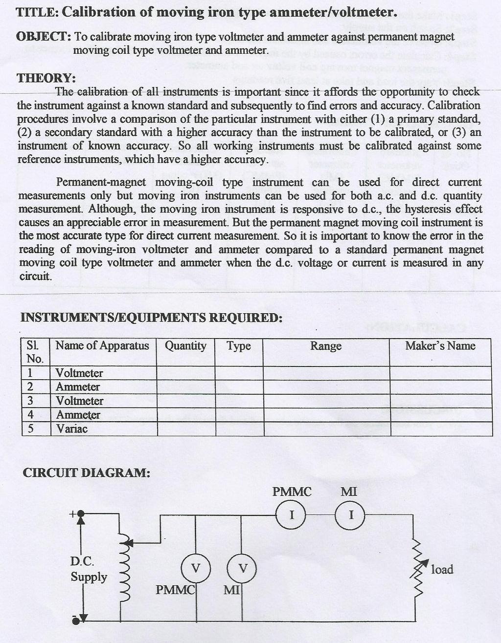
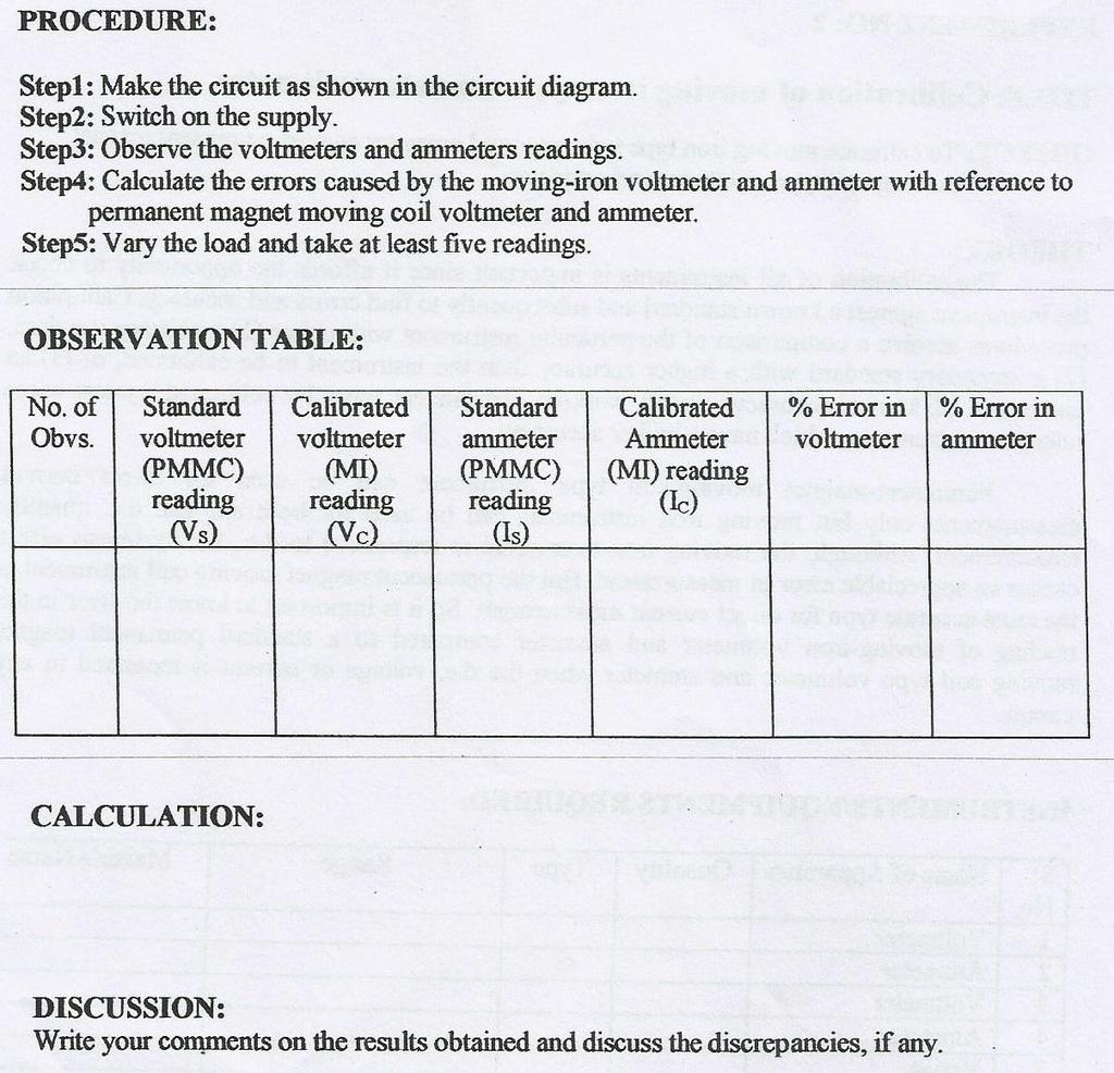
1 EXPERIMENT NO : 1 TITLE: Introduction to various Basic Instruments of Electrical Science OBJECTIVE: Introduction to various Supply Systems, Ammeter, Voltmeter, Wattmeter, Energy meter, Tachometer, Rheostat, Loading Devices, Transformer. APPARATUS REQUIRED: Demonstration of various instruments like Ammeter, Voltmeter, Wattmeter, Energy Meter, Tachometer, Rheostat, Various Capacitors, Various Resistors, AC and DC Power Supply. THEORY OF EXPERIMENT: AMMETER Ammeter is employed for measuring of current in a circuit and connected in series in the circuit. As ammeter is connected in series, the voltage drop across ammeter terminals is very low. This requires that the resistance of the ammeter should be as low as possible. The current coil of ammeter has low current carrying capacity whereas the current to be measured may be quite high. So for protecting the equipment a low resistance is connected in parallel to the current coil and it is known as shunt resistance Analog Ammeter VOLTMETER Voltmeter is employed to measure the potential difference across any two points of a circuit. It is connected in the parallel across any element in the circuit. The resistance of voltmeter is kept very high by connecting a high resistance in series of the voltmeter with the current coil of the instrument. The actual voltage drop across the current coil of the voltmeter is only a fraction of the total voltage applied across the voltmeter which is to be measured.


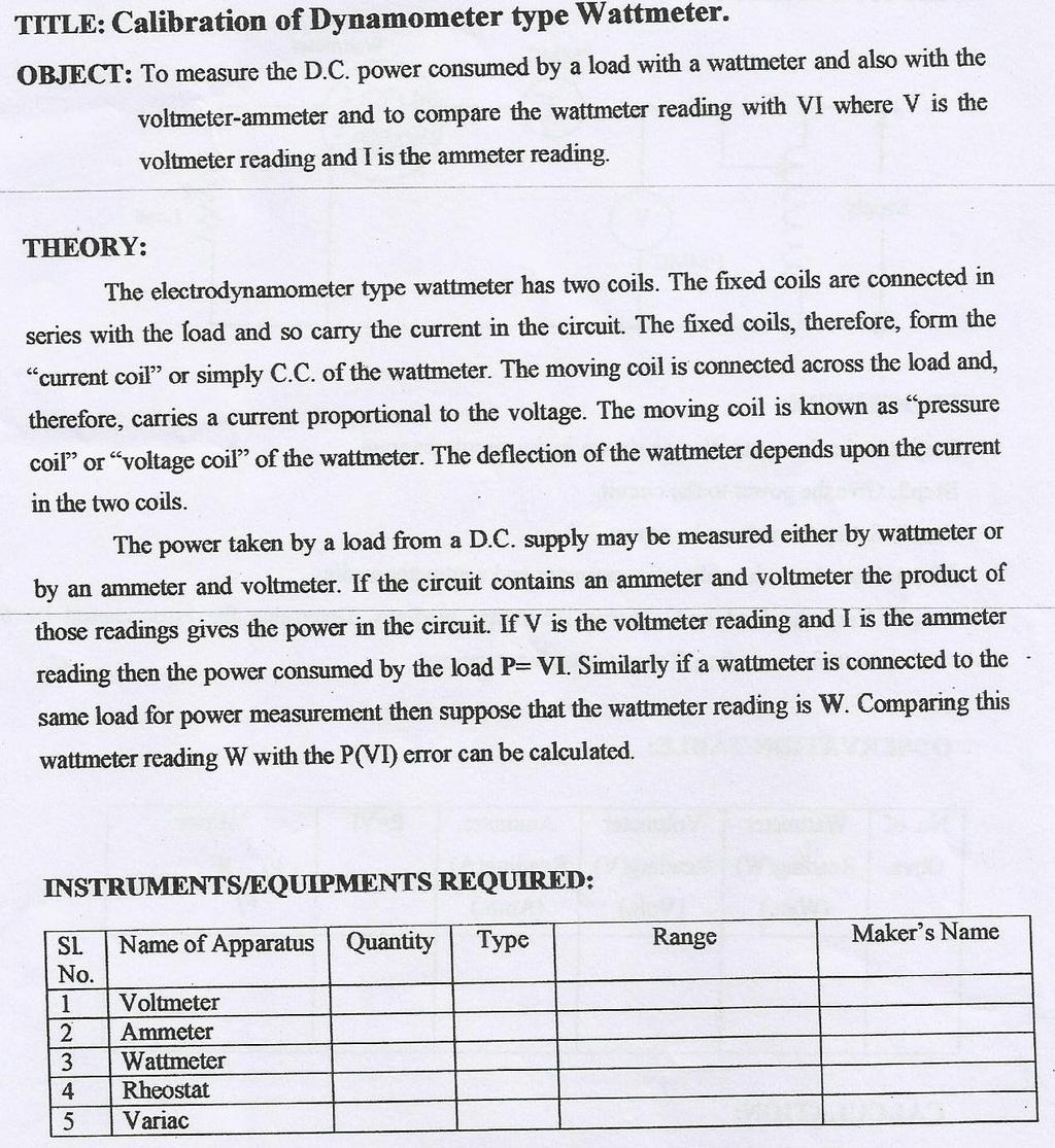
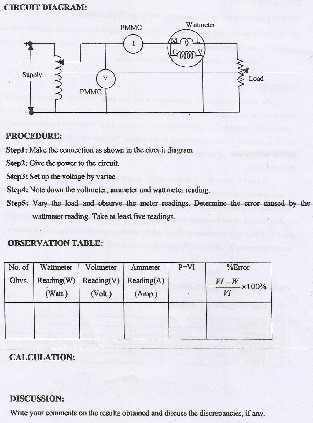
2 WATTMETER Analog voltmeter The measurement of real power in AC circuits is done by using an instrument using Wattmeter. The real power in AC circuits is given by expression VI cos where, cos is power factor. A wattmeter has two coils, namely, current coil and pressure coil. The current coil (CC) is connected in series with the load and the pressure coil (PC) is connected across the load. Watt meters are available in dual range for voltages as well as for current Internal Cicuit of Wattmeter Wattmeter ENERGY METER Energy meter is an instrument which is used to measure the consumption of electric energy in a circuit (DC or AC). It measures energy in kwh. The essential difference between a energy meter and a wattmeter is that the former is fitted with some type of registration mechanism where by all the instantaneous readings of power are summed over a definite period of time whereas the latter indicates the value at particular instant when it is read.


3 Energy Meter TACHOMETER Tachometer is an instrument to measure the speed in (revolutions per minute (r.p.m.)).the speed of a rotating shaft is measured by inserting the tapered projected part of the tachometer into the tapered hole in the rotating shaft speed of which is to be measured. RHEOSTAT Tachomet er Rheostats are made up of high resistivity material, like, nickel-chromium iron alloy closely wound over a circular tube. These are available both in single tube and double tube. Inter-turn insulation is provided to avoid short circuiting of turns. The tube of rheostat is made of insulating material, like asbestos. These are employed at places where resistance of a circuit is to be varied without breaking the circuit. LOADING DEVICES Rheostater The most commonly used loading devices are (1) lamp Bank (2) loading Rheostat. Lamp Bank load consists of number of lamps connected to form a load. These are suitably connected and controlled by a no. of switches. The switches are provided in a manner so that it should be possible to switch on any required no. of lamps at a time.

 Single phase-230v: In this system we have two wires, one is known as phase/line and the other is neutral. Voltage between them is 230 V.")
 DC Supply System There are two type of D.")
4 A loading rheostat type of load consists of no. of identical resistive elements. These elements are connected in series or parallel. The rheostat is made up of high resistivity material such as like nickelchromium. The elements of the load can be designed to take 1A, 2A or 4 A of current. VAROIUS SUPPLY SYSTEM Loading Rheostat (a) A.C supply systems: There are two types of supply. (i) Single phase-230v: In this system we have two wires, one is known as phase/line and the other is neutral. Voltage between them is 230 V. (ii) Three phase V (line to line): In his system we have three wires, one for each phase or line. In case the fourth wire is there it is neutral. While voltage between two phases/lines is 400 V, between any phase/line and neutral it is 230 V. (b) DC Supply System There are two type of D.C supply system (i)from battery: We use rectifiers for 6V or 12V D.C supply current. (ii)from generator DC Supply AC Supply MULTIMETER Multimeter is a measuring instrument used to measure the current,voltage and resistance.these can be used to troubleshoot many electrical equipments such as domestic appliances,power supplies etc.


5 Multimeter TRANSFORMER: A transformer is a static device which consists of two or more stationary electric circuits interlinked by a common magnetic circuit for the purpose of transferring electrical energy between them. The transfer of electric energy takes place from one circuit to another circuit without change in frequency. Transformer may be for stepping up voltage from low to high or stepping down voltage from high to low. Single Phase Transformer Auto Transformer REFERENCES Books 1. Electrical Science by J. B. Gupta 2. A Text book of Electrical Technology by B. L. Thereja Vol Electrical Engineering Fundamentals by Del Toro 4. Electric Circuits by James Nelson (Pearson publication) 5. Basic Electrical Engg. By DC Kulshreshtha, TMHill. URL s
6 LAB TUTORIALS 1. What are the basic measuring instruments for measuring electrical quantities? 2. What is the working principle of wattmeter and an energy meter? 3. What are the various safety measures to be taken while performing practical work in electrical science lab? 4. Discuss various types of resistors and capacitors? 5 Define the term ideal current and ideal voltage source?
7 EXPERIMENT NO : 2
8
9 EXPERIMENT NO : 3
10
11 EXPERIMENT NO : 4 TITLE: CALIBRATION OF 1 PHASE ENERGY METER OBJECTIVE: To calibrate an Energy meter by phantom loading method. APPARATUS: Name of the apparatus Type Quantity Range 1-ph Energy meter Digital Wattmeter Digital Voltmeter Digital Ammeter 1-ph Auto-transformer Stop watch THEORY : The calibration of energy meter becomes inaccurate during its rigorous use due to various reasons. It is necessary to calibrate the meter to determine the error, so that same meter can be used for correct measurement of energy. Phantom loading is performed in this experiment because the current rating of the meter under test is high. The driving system of the meter consists of current coil connected in series with load and shunt coil connected in parallel to the supply. The moving system consists of a non-magnetic material and light material i.e aluminum disc. This disc is positioned in the air gap between series and shunt magnets. A permanent magnet is positioned near the edge of the aluminum disc, which forms the braking system. At steady speed of the disc, the driving torque is equal to the braking torque. For 1200 rev. the meter reads 1 KWh So, for x revolutions the meter reads x/1200 KWh % error in speed = Actual r.p.m True r.p.m x 100 Actual r.p.m % error in measurement = Measured Energy in kwh Actual energy in kwh x 100 Measured Energy in kwh No.of revolutions in given time Nth = T x P (in watts) 3000 % error = Nth - Na x 100 Nth So, for x revolutions the meter reads x/1200 KWh % error in speed = Actual r.p.m True r.p.m x 100 % error in measurement = Actual r.p.m Measured Energy in kwh Actual energy in kwh x 100 Measured Energy in kwh

12 No.of revolutions in given time Nth = T x P (in watts) 3000 % error = Nth - Na x 100 Nth PROCEDURE : 1. Connect the circuit as shown in figure 2. Keep the auto transformer at zero position. 3. Increase the current in the current coil of the energy meter till the current reaches its maximum value of 5A. 4. Ensure the direction of the rotation of the disc in the energy meter as per the direction marked. 5. Record the time and wattmeter reading for every 10 revolution at different values of current. CIRCUIT DIAGRAM:
13 Observation: S.No V I P Time for 10 No. of Rev. % error (volts) ( amps) (KW) Rev. 1 sec in Time Result : The given energy meter is calibrated using calibrated wattmeter, voltmeter and ammeter. DISCUSSTION: Write your comments on the results obtained and discuss the discrepancies, if any.

14 EXPERIMENT NO : 5 TITLE: KELVIN S DOUBLE BRIDGE OBJECTIVE: To determine the value of the resistance f the given wire using Kelvin s Double Bridge APPARATUS: S.NO Equipment Range Type Quantity 1 Kelvin s Double Bridge 2 DC Power supply Rheostat Standard 3 resistance 4 boxes 5 Galvanometer 6 Connecting Wires THEORY: The KDB is a modification of the wheat stone Bridge (WB) and provides increased accuracy in the measurement of low resistance s. The resistance s of the lead and contact resistance of which is a major source of error in the WB is overcome in this method. The KDB incorporates the idea of a second set of ratio arms hence the name Double Bridge and the use of four terminal resistor for the law resistance arms. As shown in the figure the first of ratio arms is P & Q. The second set of ratio arms, P and V, is used to connect the galvanometer to point D at the appropriate potential between points M and N to eliminate the effect of connecting lead of resistance R between the known resistance R and the Standard resistance S. The ratio P/Q is made equal to p/q. under balance conditions there is no current through the galvanometer, which means that the voltage drop between a and b, Eab is equal to the voltage drop E and I between a and c The last equation indicates that the resistance of connecting lead, r has no effect on the measurement. Provided that the two sets of ratio arms equal ratios. The last but one equation above, shows that the error that is introduced in case the ratios are not exactly equal it indicates that it is desirable to keep as possible in order to minimize the errors in case there is a difference between ratios. P/Q and p/q. The effect of thermo electric emfs can be eliminated by making another measurement with the battery connections revered. The true value of R being the mean of the two readings. CIRCUIT DIAGRAM: P, p, Q, q Known decade resistances R Unknown resistance whose value is to be determined.
15 S Standard resistance. Rb Regulating resistance. G Galvanometer. K Key switch. PROCEDURE: 1. The connections as per the circuit diagram. 2. Keep Q = q = 1000 ohms and S = 1 ohm. The ratio P/Q should a. always be kept equal to p/q. as Q =q, we must keep P = p. b. To start with P and p may be kept at zero position. 3. Switch on the DC power supply and adjust the voltage to about 2 a. volts with the regulating resistance cut in fully. 4. Adjust P and p simultaneously to get balance. If a light spot 5. Galvanometer is used, then increases the sensitivity in steps and a. get exact balance in the direct portion. Bring back the sensitivity b. Knob of the galvanometer to the starting position. 6. Note the value of P. 7. Repeat steps (3) and (4) reversing the DC power supply polarity. 8. Repeat steps (3) to (5) above fo 9. Q = q = 100 ohms, 10 ohms, 1 ohms choosing suitable values for S a. So that the value of p at balance is obtained in hundreds. 10. The unknown resistance is calculated in each case using the Formula R = P/Q.S OBSERVATION: S.No Main dial Slide wire Multiplier PRECAUTIONS: 1. In the case of a light spot galvanometer, the sensitivity knob of the galvanometer should be in the shorted position when the bridge isunbalanced. It should be brought back to shorted position from thedirect position, immediately after obtaining balance. 2. The DC power regulating resistance (R b) should be cut in fully tostart with and adjusted RESULT: later if necessary to get larger deflection. DISCUSSION: Write your comments on the results obtained and discuss the discrepancies, if any.
16 EXPERIMENT NO : 6
17
18
19 EXPERIMENT NO : 7 Title: Measurement of 3 Phase Power by 2 Wattmeters OBJECTIVE: Measurement of power by 2-wattmeters for balanced loads in a 3-phase circuit.apparatus: Sl. No. Name of the apparatus Type Quantity Range 1 3 pole Fuse Switch 2 U.P.F. Wattmeters 3 Ammeter 4 Voltmeter THEORY : In a 3-phase, 3-wire system, power can be measured using two watttmeters for balance and unbalanced loads and also for star, delta type loads. This can be verified by measuring the power consumed in each phase. In this circuit, the pressure coils are connected between two phase such that one of the line is coinciding for both the meters. P1 + P2 = 3 VPh IPh COSø Power factor Cosø = Cos ( tan -1 3 ((P1 P2)/( P1 +P2))) PROCEDURE: a) Connect the circuit as shown in the circuit diagram. b) Keep all the toggle switches in ON condition. c) Switch on equal loads on each phase i.e. balanced load must be maintained with different load combinations. d) Connect the ammeter in R-Phase and then switch OFF the toggle switch connected across the ammeter symbol. e) Connect the pressure coils of two wattmeter across R-Y phase and B-Y phase respectively, current coil in R-phase and B-phase. f) For different balanced loads take readings of wattmeters W1 and W2.
20 CIRCUIT DIAGRAM: OBSERVATIONS: Type of Load (W) W1 KW W2 KW I1 Amps I2 Amps Vph Volts W1+ W2 KW P KW R Y B (W1+ W2) P W1 W2 IR IB Vph X2 KW RESULT: Measurement of power by 2-wattmeters for balanced loads in a 3-phase circuit is determined. DISCUSSION: Write your comments on the results obtained and discuss the discrepancies, if any.
21 EXPERIMENT NO : 8 TITLE: Wien s Bridge OBJECTIVE: To determine the unknown frequency of a circuit. THEORY: Wien Bridge has a series RC combination in one and a parallelcombination in the adjoining arm. Wien's bridge shown in fig 2.1. its basic form is designed to measure f r e qu ency. It can also be used for the instrument of an unknown capacitor with great accuracy, The impedance of one arm is The admittance of the parallelarm is Using the bridge balance equation,we have We have Therefore Equating the real and imaginary terms we have as,
22 Therefore, And,... (1.1) The two conditions for bridge balance, (1.1) and (1.3), result in an expression determining the required resistance ratio R2/R4 and another express determining the frequency of the applied voltage. If we satisfy Eq. (1.1) an also excite the bridge with the frequency of Eq. (1.3), the bridge will be balanced. In most Wien bridge circuits, the components are chosen such that R 1 = R3 = R and C1 = C3 = C. Equation (1.1) therefore reduces to R2IR4 =2 at Eq. (1.3) to f= 1/2ПRC, which is the general equation for the frequency of fl bridge circuit. The bridge is used for measuring frequency in the audio range. Resistances R1 and R3 can be ganged together to have identical values. Capacitors C1 and C3 are normally of fixed values The audio range is normally divided into k - 20 khz range In this case, the resistances can be used for range changing and capacitors, and C3 for fine frequency control within the range. The bridge can also be use for measuring capacitance. In that case, the frequency of operation must be known. The bridge is also used in a harmonic distortion analyzer, as a Notch filter, an in audio frequency and radio frequency oscillators as a frequency determine element. An accuracy of 0.5% - 1% can be readily obtained using this bridge. Because it is frequency sensitive, it is difficult to balance unless the waveform of the applied voltage is purely sinusoidal. OBSERVATION: Sl. No. I in AMPS V in volts Wattmeter Reading Power factor % Error
23 PRECAUTIONS: 1. Instruments used should be of proper range. 2. All the connections should be tight. RESULT: DISCUSSTION: Write your comments on the results obtained and discuss the discrepancies, if any.
24 EXPERIMENT NO : 9 TITLE: ANDERSON S BRIDGE OBJECTIVE: To determine the unknown value of inductance using Anderson s bridge. APPARATUS: Sl. No. Name of the apparatus Type Quantity Range 1 Transformer 2 Bread board 3 Resistors 4 Variable Resistor 5 Capacitors 6 Inductors 7 Digital Multimeter THEORY: In this bridge, the self inductance is measured in terms of a standard capacitor. This method is applicable for precise measurement of self-inductance over a very wide range of values. Figures below show the connections and the phasor diagram of the bridge for balanced conditions. Let L1 = self inductance to be measured,r1 = resistance of self-inductor, r,r2,r3,r4 = known non-inductive resistance,r1 = resistance connected in series with self-inductor,
 = I2R2 + ICr, and IC(r+1/jωC) = (I2-IC) R4 By substituting IC value and equating real and imaginary parts R1 = R2R3/R4 r1 L1 = C R3/R4{ r(r4+r2)+r2r4} PROCEDURE: 1.")
25 At, balance, I 1 =I 3 and I 2 = I C +I 4. Now, I1R3= IC/jωC, therefore, IC= I1jωCR3 Writing the other balance equations. I1(r1+R1+jωL1) = I2R2 + ICr, and IC(r+1/jωC) = (I2-IC) R4 By substituting IC value and equating real and imaginary parts R1 = R2R3/R4 r1 L1 = C R3/R4{ r(r4+r2)+r2r4} PROCEDURE: 1. Connect the circuit as shown in the figure. 2. Connect the unknown inductance in L1. 3. Select any value of r. 4. Connect the multimeter between ground and output of imbalance amplifier. 5. Vary r1 and r, from minimum position, in clockwise direction. 6. Calculate the inductance L1 by substituting known values. OBSERVATION: Actual value of L in mh R in ohms Practical value of L in mh RESULT: DISCUSSION: if any. Write your comments on the results obtained and discuss the discrepancies,
26 EXPERIMENT NO : 10 TITLE: DESAUTY S BRIDGE OBJECTIVE:To determine the unknown value of capacitance using Desauty s bridge. Apparatus: Sl. No. Name of the apparatus Type Quantity Range 1 Transformer 2 Bread board 3 Resistors 4 Variable Resistor 5 Capacitors 6 Digital Multimeter THEORY: The bridge is the simplest of comparing two capacitances. The connections and the phasor diagram of this bridge are shown below. Let C1 = Capacitor whose capacitance is to be measured. C2 = A standard capacitor R3, R4 = Non-inductive resistors. The balance can be obtained by varying either R3 or R4. Resistors R1 and R2 are connected in series with C1 and C2 respectively. r1 and r2 are small resistances representing the loss component of the two capacitors.
27 At balance, (R1+ r1+ 1/jωC1) R4 = (R2+ r2+1/jωc2) R3 From which we have C1/C2 = R4/R3. Figure b shows the phasor diagram of the bridge under balance conditions. The angles δ1 and δ2 are the phase angles of capacitors C1and C2 respectively. Dissipation factor for the capacitors are D1 = tan δ1 =ω C1r1 and D2 = tan δ2 =ω C2r2 D2 D1 = ω C2(R1R4/R3 R2) Therefore, if the dissipation factor of one of the capacitors is known, the dissipation factor for the other can be determined. PROCEDURE: 1. Connect the circuit as shown in the figure. 2. Connect the unknown capacitor in C1. 3. Select any value of R3. 4. Connect the multimeter between ground and output of imbalance amplifier. 5. Vary R2, from minimum position, in clockwise direction. 6. If the selection of R3 is correct the balance point can be obtained at minimum position. 7. If that is not the case, select another R3. 8. Since, the unknown capacitance whose resistive effect would be made for capacitive form and R2 is adjusted for minimum output. OBSERVATION: Sl.NO R3 R2 C2 C1= R2C2/R3 True Value of C1 RESULT: DISCUSSION: Write your comments on the results obtained and discuss the discrepancies, if any.
28 EXPERIMENT NO : 11 TITLE: SCHERING S BRIDGE OBJECTIVE: To determine the unknown value of capacitance using schering s bridge. APPARATUS: Sl. No. Name of the apparatus Type Quantity Range 1 Bread board 2 Resistors 3 Variable Resistor 4 Capacitors 5 Digital Multimeter THEORY: Schering bridge is one of the most important of the a.c. bridge. It is extensively used in measurement of capacitance. At balance, {r1+ 1/(jωC1)} {R4/(1+jωC4R4)} = R3/(jωC2) {r1+ 1/(jωC1)} R4 = R3/(jωC2) *{(1+jωC4R4)} r1r4 {(jr4)/(ωc1)} ={ (-jr3)/(ωc2)} + {(R3R4C4)/(C2)} Equating real and imaginary terms, r1 = R3C4/C2 and C1 = C2R4/R3
29 PROCEDURE: 1. Connect the circuit as shown in the figure. 2. Select any value of C1. 3. Connect the multimeter between ground and output of imbalance amplifier. 4. Vary R4 and C4, from minimum position, in clockwise direction. 5. If the selection of C1 is correct the balance point can be obtained at minimum position. 6. If that is not the case, select another C1. 7. Calculate the Capacitance by substituting known values. OBSERVATION: C4 C1 C2 R3 R4 RESULT: Hence the balanced condition of schering bridge is obtained and unknown value of capacitance is found. DISCUSSION: Write your comments on the results obtained and discuss the discrepancies, if any.
Electronic Measurements & Instrumentation. 1. Draw the Maxwell s Bridge Circuit and derives the expression for the unknown element at balance?
 UNIT -6 1. Draw the Maxwell s Bridge Circuit and derives the expression for the unknown element at balance? Ans: Maxwell's bridge, shown in Fig. 1.1, measures an unknown inductance in of standard arm offers
SIR C R REDDY COLLEGE OF ENGINEERING EEE Department, ELURU.
 EEE3110-ELECTRICAL MEASUREMENTS LAB III/IV EEE, I Semester SIR C R REDDY COLLEGE OF ENGINEERING EEE Department, ELURU. NAME:. REGD.NO: SECTION:..Academic Year:.. SIR.C.R.REDDY COLLEGE OF ENGINEERING
Bhoj Reddy Engineering College for Women, Hyderabad Department of Electronics and Communication Engineering Electrical and Electronics Instrumentation
 Bhoj Reddy Engineering College for Women, Hyderabad Department of Electronics and Communication Engineering Electrical and Electronics Instrumentation Academic Year: 2016-17 III B Tech II Semester Branch:
ELECTRICAL MEASUREMENTS
 R10 Set No: 1 1. a) Derive the expression for torque equation for a moving iron attraction type instrument and comment up on the nature of scale [8] b) Define the terms current sensitivity, voltage sensitivity
DEPARTMENT OF ELECTRICAL ENGINEERING
 DEPARTMENT OF ELECTRICAL ENGINEERING LAB MANUAL SUBJECT: EMI B.TECH -3 RD SEM KCT COLLEGE OF ENGG & TECH FATEHGARH PUNJAB TECHNICAL UNIVERSITY Prepared by:- Er. Prince Munjal (AP) B.Tech (EE) M.Tech( EE)
SRI SUKHMANI INSTITUTE OF ENGINEERING & TECHNOLOGY DERA BASSI DEPARTMENT: ELECTRONICS & COMM. LABORATORY MANUAL LAB: EMI SUBJECT CODE: SEMESTER: 4th
 SRI SUKHMANI INSTITUTE OF ENGINEERING & TECHNOLOGY DERA BASSI DEPARTMENT: ELECTRONICS & COMM. LABORATORY MANUAL LAB: EMI SUBJECT CODE: SEMESTER: 4th EXPERIMENT NO-1 Aim:- Low Resistance Using Kelvin Double
Table of Contents...2. About the Tutorial...6. Audience...6. Prerequisites...6. Copyright & Disclaimer EMI INTRODUCTION Voltmeter...
 1 Table of Contents Table of Contents...2 About the Tutorial...6 Audience...6 Prerequisites...6 Copyright & Disclaimer...6 1. EMI INTRODUCTION... 7 Voltmeter...7 Ammeter...8 Ohmmeter...8 Multimeter...9
Measurement of Resistance and Potentiometers
 Electrical Measurements International Program Department of Electrical Engineering UNIVERSITAS INDONESIA Measurement of Resistance and Potentiometers Jahroo Renardi Lecturer : Ir. Chairul Hudaya, ST, M.Eng.,
SIDDHARTH GROUP OF INSTITUTIONS :: PUTTUR (AUTONOMOUS) Siddharth Nagar, Narayanavanam Road QUESTION BANK (DESCRIPTIVE)
 Siddharth Nagar, Narayanavanam Road QUESTION BANK (DESCRIPTIVE)") SIDDHARTH GROUP OF INSTITUTIONS :: PUTTUR (AUTONOMOUS) Siddharth Nagar, Narayanavanam Road 517583 QUESTION BANK (DESCRIPTIVE) Suject : Electrical & Electronic Measurements(16EE224) Year & Sem: III-B.Tech
SIDDHARTH GROUP OF INSTITUTIONS :: PUTTUR (AUTONOMOUS) Siddharth Nagar, Narayanavanam Road 517583 QUESTION BANK (DESCRIPTIVE) Suject : Electrical & Electronic Measurements(16EE224) Year & Sem: III-B.Tech
Dhanalakshmi Srinivasan Institute of Technology, Samayapuram, Trichy. Cycle 2 EE6512 Electrical Machines II Lab Manual
 Cycle 2 EE652 Electrical Machines II Lab Manual CIRCUIT DIAGRAM FOR SLIP TEST 80V DC SUPPLY 350Ω, 2 A 3 Point Starter L F A NAME PLATE DETAILS: 3Ф alternator DC shunt motor FUSE RATING: Volts: Volts: 25%
Electrical Machines (EE-343) For TE (ELECTRICAL)
 For TE (ELECTRICAL)") PRACTICALWORKBOOK Electrical Machines (EE-343) For TE (ELECTRICAL) Name: Roll Number: Year: Batch: Section: Semester: Department: N.E.D University of Engineering &Technology, Karachi Electrical Machines
PRACTICALWORKBOOK Electrical Machines (EE-343) For TE (ELECTRICAL) Name: Roll Number: Year: Batch: Section: Semester: Department: N.E.D University of Engineering &Technology, Karachi Electrical Machines
UNIT II MEASUREMENT OF POWER & ENERGY
 UNIT II MEASUREMENT OF POWER & ENERGY Dynamometer type wattmeter works on a very simple principle which is stated as "when any current carrying conductor is placed inside a magnetic field, it experiences
EE ELECTRICAL ENGINEERING AND INSTRUMENTATION
 EE6352 - ELECTRICAL ENGINEERING AND INSTRUMENTATION UNIT V ANALOG AND DIGITAL INSTRUMENTS Digital Voltmeter (DVM) It is a device used for measuring the magnitude of DC voltages. AC voltages can be measured
ELECTRICAL ENGINEERING LABORATORY MANUAL (NEE 151/251)
") ELECTRICAL ENGINEERING LABORATORY MANUAL (NEE 151/251) DEPARTMENTS OF ELECTRONICS & COMMUNICATION ENGINEERING/ ELECTRICAL ENGINEERING 27, Knowledge Park-III, Greater Noida, (U.P.) Phone: 0120-2323854-58
ELECTRICAL ENGINEERING LABORATORY MANUAL (NEE 151/251) DEPARTMENTS OF ELECTRONICS & COMMUNICATION ENGINEERING/ ELECTRICAL ENGINEERING 27, Knowledge Park-III, Greater Noida, (U.P.) Phone: 0120-2323854-58
ELECTROMAGNETIC INDUCTION AND ALTERNATING CURRENT (Assignment)
") ELECTROMAGNETIC INDUCTION AND ALTERNATING CURRENT (Assignment) 1. In an A.C. circuit A ; the current leads the voltage by 30 0 and in circuit B, the current lags behind the voltage by 30 0. What is the
ELECTROMAGNETIC INDUCTION AND ALTERNATING CURRENT (Assignment) 1. In an A.C. circuit A ; the current leads the voltage by 30 0 and in circuit B, the current lags behind the voltage by 30 0. What is the
UNIT II MEASUREMENT OF POWER AND ENERGY PART-A
 UNIT II MEASUREMENT OF POWER AND ENERGY PART-A 1. A 3 500 V motor load has a pf of 0.4. Two wattmeters connected to measure the input. They show the input to be 30 kw. Find the reading of each instrument
Note: 1. All the students must strictly follow all the safety precautions. 2. In case of any question or concern, please contact LAB INSTRUCTOR or TA.
 UNIVERSITY OF WATERLOO ELECTRICAL & COMPUTER ENGINEERING DEPARTMENT FALL 2006 E&CE 261: Energy Systems and Components EXPERIMENT 1: THREE-PHASE SYSTEMS Contents covered in this laboratory exercise: 1.
(Approved by AICTE & Affiliated to Calicut University) DEPARTMENT OF ELECTRICAL & ELECTRONICS ENGINEERING : ELECTRICAL MEASUREMENTS AND
 DEPARTMENT OF ELECTRICAL & ELECTRONICS ENGINEERING : ELECTRICAL MEASUREMENTS AND") (Approved by AICTE & Affiliated to Calicut University) DEPARTMENT OF ELECTRICAL & ELECTRONICS ENGINEERING ELECTRICAL MEASUREMENTS AND INSTRUMENTATION LAB CLASS SEMESTER SUBJECT CODE SUBJECT : II YEAR (EEE)
(Approved by AICTE & Affiliated to Calicut University) DEPARTMENT OF ELECTRICAL & ELECTRONICS ENGINEERING ELECTRICAL MEASUREMENTS AND INSTRUMENTATION LAB CLASS SEMESTER SUBJECT CODE SUBJECT : II YEAR (EEE)
Sine waves by far the most important form of alternating quantity important properties are shown below
 AC DC METERS 1 Sine waves by far the most important form of alternating quantity important properties are shown below 2 Average value of a sine wave average value over one (or more) cycles is clearly zero
 VIDYARTHIPLUS - ANNA UNIVERSITY ONLINE STUDENTS COMMUNITY UNIT 1 DC MACHINES PART A 1. State Faraday s law of Electro magnetic induction and Lenz law. 2. Mention the following functions in DC Machine (i)
Aligarh College of Engineering & Technology (College Code: 109) Affiliated to UPTU, Approved by AICTE Electrical Engg.
 Affiliated to UPTU, Approved by AICTE Electrical Engg.") Aligarh College of Engineering & Technology (College Code: 19) Electrical Engg. (EE-11/21) Unit-I DC Network Theory 1. Distinguish the following terms: (a) Active and passive elements (b) Linearity and
Aligarh College of Engineering & Technology (College Code: 19) Electrical Engg. (EE-11/21) Unit-I DC Network Theory 1. Distinguish the following terms: (a) Active and passive elements (b) Linearity and
MEASUREMENTS & INSTRUMENTATION ANALOG AND DIGITAL METERS
 MEASUREMENTS & INSTRUMENTATION ANALOG AND DIGITAL METERS ANALOG Metering devices Provides monotonous (continuous) movement. ELECTRICAL MEASURING INSTRUMENTS ANALOG METERS A d Arsonval galvanometer (Moving
Code No: RR Set No. 1
 Code No: RR310202 Set No. 1 III B.Tech I Semester Regular Examinations, November 2006 ELECTRICAL MEASUREMENTS (Electrical & Electronic Engineering) Time: 3 hours Max Marks: 80 Answer any FIVE Questions
EE Chapter 7 Measuring Instruments
 EE 2145230 Chapter 7 Measuring Instruments 7.1 Meter Movements The basic principle of many electric instruments is that of the galvanometer. This is a device which reacts to minute electromagnetic influences
INSTITUTE OF AERONAUTICAL ENGINEERING (Autonomous) Dundigal, Hyderabad ELECTRICAL AND ELECTRONICS ENGINEERING
 Dundigal, Hyderabad ELECTRICAL AND ELECTRONICS ENGINEERING") INSTITUTE OF AERONAUTICAL ENGINEERING (Autonomous) Dundigal, Hyderabad - 500 043 ELECTRICAL AND ELECTRONICS ENGINEERING QUESTION BANK Course Name : Electrical and Electronics Instrumentation Course Code
INSTITUTE OF AERONAUTICAL ENGINEERING (Autonomous) Dundigal, Hyderabad - 500 043 ELECTRICAL AND ELECTRONICS ENGINEERING QUESTION BANK Course Name : Electrical and Electronics Instrumentation Course Code
KKR & KSR INSTITUTE OF TECHNOLOGY & SCIENCES. Handouts
 KKR & KSR INSTITUTE OF TECHNOLOGY & SCIENCES (Approved by AICTE, New Delhi, Affiliated to JNTU Kakinada, Accredited by NAAC with A Grade) DEPARTMENT OF ELECTRICAL AND ELECTRONICS ENGINEERING Handouts Subject:
ECE215 Lecture 7 Date:
 Lecture 7 Date: 29.08.2016 AC Circuits: Impedance and Admittance, Kirchoff s Laws, Phase Shifter, AC bridge Impedance and Admittance we know: we express Ohm s law in phasor form: where Z is a frequency-dependent
UNIVERSITY OF TECHNOLOGY, JAMAICA SCHOOL OF ENGENEERING. Electrical Engineering Science. Laboratory Manual
 UNIVERSITY OF TECHNOLOGY, JAMAICA SCHOOL OF ENGENEERING Electrical Engineering Science Laboratory Manual Table of Contents Experiment #1 OHM S LAW... 3 Experiment # 2 SERIES AND PARALLEL CIRCUITS... 8
Experiment No. Experiments for First Year Electrical Engg Lab
 Experiment No im: To determine Regulation and Efficiency of a single phase transformer using open circuit (O.C.) and short circuit (S.C.) tests pparatus: - Single phase transformer Single phase dimmer
ELECTRICAL CIRCUITS LABORATORY MANUAL (II SEMESTER)
") ELECTRICAL CIRCUITS LABORATORY MANUAL (II SEMESTER) LIST OF EXPERIMENTS. Verification of Ohm s laws and Kirchhoff s laws. 2. Verification of Thevenin s and Norton s Theorem. 3. Verification of Superposition
ELECTRICAL CIRCUITS LABORATORY MANUAL (II SEMESTER) LIST OF EXPERIMENTS. Verification of Ohm s laws and Kirchhoff s laws. 2. Verification of Thevenin s and Norton s Theorem. 3. Verification of Superposition
UNIVERSITY OF TECHNOLOGY By: Fadhil A. Hasan ELECTRICAL MACHINES
 UNIVERSITY OF TECHNOLOGY DEPARTMENT OF ELECTRICAL ENGINEERING Year: Second 2016-2017 By: Fadhil A. Hasan ELECTRICAL MACHINES І Module-II: AC Transformers o Single phase transformers o Three-phase transformers
 DEPARTMENT OF ELECTRICAL AND ELECTRONICS ENGINEERING EE6511 CONTROL AND INSTRUMENTATION LABORATORY MANUAL 2016-2017 ODD SEMESTER INDEX Sl. No. Date of Expt. Name of the Experiment Page No. Marks Staff
Question Bank SENSORS AND INSTRUMENTATION [EE-305/405]
![Question Bank SENSORS AND INSTRUMENTATION [EE-305/405]](/thumbs/95/124646158.jpg "Question Bank SENSORS AND INSTRUMENTATION [EE-305/405]") UNIT-1 1. Discuss liquid in glass thermometers? 2. Write a short note on strain gauges. 3. Mention the various temperature scales and relation between them. 4. An experiment is conducted to calibrate a
UNIT-1 1. Discuss liquid in glass thermometers? 2. Write a short note on strain gauges. 3. Mention the various temperature scales and relation between them. 4. An experiment is conducted to calibrate a
Lecture 36 Measurements of High Voltages (cont) (Refer Slide Time: 00:14)
 (Refer Slide Time: 00:14)") Advances in UHV Transmission and Distribution Prof. B Subba Reddy Department of High Voltage Engg (Electrical Engineering) Indian Institute of Science, Bangalore Lecture 36 Measurements of High Voltages
Advances in UHV Transmission and Distribution Prof. B Subba Reddy Department of High Voltage Engg (Electrical Engineering) Indian Institute of Science, Bangalore Lecture 36 Measurements of High Voltages
SHRI RAMSWAROOP MEMORIAL COLLEGE OF ENGG. & MANAGEMENT B.Tech. [SEM I (EE, EN, EC, CE)] QUIZ TEST-3 (Session: ) Time: 1 Hour ELECTRICAL ENGINEE
![SHRI RAMSWAROOP MEMORIAL COLLEGE OF ENGG. & MANAGEMENT B.Tech. [SEM I (EE, EN, EC, CE)] QUIZ TEST-3 (Session: ) Time: 1 Hour ELECTRICAL ENGINEE](/thumbs/94/118213481.jpg "SHRI RAMSWAROOP MEMORIAL COLLEGE OF ENGG. & MANAGEMENT B.Tech. [SEM I (EE, EN, EC, CE)] QUIZ TEST-3 (Session: ) Time: 1 Hour ELECTRICAL ENGINEE") SHRI RAMSWAROOP MEMORIAL COLLEGE OF ENGG. & MANAGEMENT B.Tech. [SEM I (EE, EN, EC, CE)] QUIZ TEST-3 (Session: 2014-15) Time: 1 Hour ELECTRICAL ENGINEERING Max. Marks: 30 (NEE-101) Roll No. Academic/26
SHRI RAMSWAROOP MEMORIAL COLLEGE OF ENGG. & MANAGEMENT B.Tech. [SEM I (EE, EN, EC, CE)] QUIZ TEST-3 (Session: 2014-15) Time: 1 Hour ELECTRICAL ENGINEERING Max. Marks: 30 (NEE-101) Roll No. Academic/26
3. What is hysteresis loss? Also mention a method to minimize the loss. (N-11, N-12)
") DHANALAKSHMI COLLEGE OF ENGINEERING, CHENNAI DEPARTMENT OF ELECTRICAL AND ELECTRONICS ENGINEERING EE 6401 ELECTRICAL MACHINES I UNIT I : MAGNETIC CIRCUITS AND MAGNETIC MATERIALS Part A (2 Marks) 1. List
DHANALAKSHMI COLLEGE OF ENGINEERING, CHENNAI DEPARTMENT OF ELECTRICAL AND ELECTRONICS ENGINEERING EE 6401 ELECTRICAL MACHINES I UNIT I : MAGNETIC CIRCUITS AND MAGNETIC MATERIALS Part A (2 Marks) 1. List
CURRENT ELECTRICITY. 1. The S.I. unit of power is (a) Henry (b) coulomb (c) watt (d) watt-hour Ans: c
 Henry (b) coulomb (c) watt (d) watt-hour Ans: c") CURRENT ELECTRICITY 1. The S.I. unit of power is (a) Henry (b) coulomb (c) watt (d) watt-hour 2. Electric pressure is also called (a) resistance (b) power (c) voltage (d) energy 3. The substances which
CURRENT ELECTRICITY 1. The S.I. unit of power is (a) Henry (b) coulomb (c) watt (d) watt-hour 2. Electric pressure is also called (a) resistance (b) power (c) voltage (d) energy 3. The substances which
UNIVERSITY OF TECHNOLOGY, JAMAICA School of Engineering -
 UNIVERSITY OF TECHNOLOGY, JAMAICA School of Engineering - Electrical Engineering Science Laboratory Manual Table of Contents Safety Rules and Operating Procedures... 3 Troubleshooting Hints... 4 Experiment
νµθωερτψυιοπασδφγηϕκλζξχϖβνµθωερτ ψυιοπασδφγηϕκλζξχϖβνµθωερτψυιοπα σδφγηϕκλζξχϖβνµθωερτψυιοπασδφγηϕκ χϖβνµθωερτψυιοπασδφγηϕκλζξχϖβνµθ
 θωερτψυιοπασδφγηϕκλζξχϖβνµθωερτψ υιοπασδφγηϕκλζξχϖβνµθωερτψυιοπασδ φγηϕκλζξχϖβνµθωερτψυιοπασδφγηϕκλζ ξχϖβνµθωερτψυιοπασδφγηϕκλζξχϖβνµ Physics θωερτψυιοπασδφγηϕκλζξχϖβνµθωερτψ Current and Electricity υιοπασδφγηϕκτψυιοπασδφγηϕκλζξχϖβν
BASIC ELECTRICAL LAB EQUIPMENTS
 BASIC ELECTRICAL LAB EQUIPMENTS S No. Name of the Equipment Qty Model/Specification Superposition theorem kit(s) 0 Jupiter Norton's theorem kit(s) 0 Jupiter 3 Thevenin theorem kit(s) 0 Jupiter 4 Maximum
Reg. No. : BASIC ELECTRICAL TECHNOLOGY (ELE 101)
") Department of Electrical and Electronics Engineering Reg. No. : MNIPL INSTITUTE OF TECHNOLOGY, MNIPL ( Constituent Institute of Manipal University, Manipal) FIRST SEMESTER B.E. DEGREE MKEUP EXMINTION (REVISED
Department of Electrical and Electronics Engineering Reg. No. : MNIPL INSTITUTE OF TECHNOLOGY, MNIPL ( Constituent Institute of Manipal University, Manipal) FIRST SEMESTER B.E. DEGREE MKEUP EXMINTION (REVISED
1. A battery has an emf of 12.9 volts and supplies a current of 3.5 A. What is the resistance of the circuit?
 1. A battery has an emf of 12.9 volts and supplies a current of 3.5 A. What is the resistance of the circuit? (a) 3.5 Ω (b) 16.4 Ω (c) 3.69 Ω (d) 45.15 Ω 2. Sign convention used for potential is: (a) Rise
SHRI RAMSWAROOP MEMORIAL COLLEGE OF ENGG. & MANAGEMENT
 SHRI RAMSWAROOP MEMORIAL COLLEGE OF ENGG. & MANAGEMENT B.Tech. [SEM I (CE,EC,EE,EN)] QUIZ TEST-3 (Session: 2012-13) Time: 1 Hour ELECTRICAL ENGINEERING Max. Marks: 30 (EEE-101) Roll No. Academic/26 Refer/WI/ACAD/18
Jawaharlal Nehru Engineering College, Aurangabad.
 Jawaharlal Nehru Engineering College, Aurangabad. Laboratory Manual ELECTRICAL MEASUREMENT & TEACHNIQUES [EMT] For Second Year (EEP) Students Manual made by- Prof. J.S.Solanke FORWARD It is my great pleasure
Exercise 9: inductor-resistor-capacitor (LRC) circuits
 circuits") Exercise 9: inductor-resistor-capacitor (LRC) circuits Purpose: to study the relationship of the phase and resonance on capacitor and inductor reactance in a circuit driven by an AC signal. Introduction
Exercise 9: inductor-resistor-capacitor (LRC) circuits Purpose: to study the relationship of the phase and resonance on capacitor and inductor reactance in a circuit driven by an AC signal. Introduction
Anna University of Technology Madurai. Alagar kovil road, Madurai REGULATIONS -2010
 Alagar kovil road, Madurai-6 00. REGULATIONS -00 III Semester B. E. Electronics and Communication Engineering 044EC307 Digital Electronics Lab Requirement for a batch of 30 students Sl. No Name of the
RADIO AMATEUR EXAM GENERAL CLASS
 RAE-Lessons by 4S7VJ 1 CHAPTER-7 RADIO AMATEUR EXAM GENERAL CLASS MEASURMENTS By 4S7VJ 7.1 TEST EQUIPMENT & MEASUREMENTS Correct operation of amateur radio equipment involves measurements to ensure optimum
Electronic Instrument Disadvantage of moving coil meter Low input impedance High loading error for low-voltage range voltmeter
 EIE 240 Electrical and Electronic Measurement Class 6, February 20, 2015 1 Electronic Instrument Disadvantage of moving coil meter Low input impedance High loading error for low-voltage range voltmeter
15. the power factor of an a.c circuit is.5 what will be the phase difference between voltage and current in this
 1 1. In a series LCR circuit the voltage across inductor, a capacitor and a resistor are 30 V, 30 V and 60 V respectively. What is the phase difference between applied voltage and current in the circuit?
ECE 215 Lecture 8 Date:
 ECE 215 Lecture 8 Date: 28.08.2017 Phase Shifter, AC bridge AC Circuits: Steady State Analysis Phase Shifter the circuit current I leads the applied voltage by some phase angle θ, where 0 < θ < 90 ο depending
VALLIAMMAI ENGINEERING COLLEGE
 P a g e 2 Question Bank Programme Subject Semester / Branch : BE : EE6201-CIRCUIT THEORY : II/EEE,ECE &EIE UNIT-I PART-A 1. Define Ohm s Law (B.L.T- 1) 2. List and define Kirchoff s Laws for electric circuits.
Basic Analog Circuits
 Basic Analog Circuits Overview This tutorial is part of the National Instruments Measurement Fundamentals series. Each tutorial in this series, will teach you a specific topic of common measurement applications,
AC Power Instructor Notes
 Chapter 7: AC Power Instructor Notes Chapter 7 surveys important aspects of electric power. Coverage of Chapter 7 can take place immediately following Chapter 4, or as part of a later course on energy
AP Physics C. Alternating Current. Chapter Problems. Sources of Alternating EMF
 AP Physics C Alternating Current Chapter Problems Sources of Alternating EMF 1. A 10 cm diameter loop of wire is oriented perpendicular to a 2.5 T magnetic field. What is the magnetic flux through the
Basic Electrical Engineering Lab Laboratory Manual
 DEV BHOOMI INSTITUTE OF TECHNOLOGY CHAKRATA ROAD,NAVGAOUN MANDUWALA,UTTARAKHAND Programs: B.TECH. (Electrical and Electronics Engineering) Basic Electrical Engineering Lab Laboratory Manual PREPARED BY
VALLIAMMAI ENGINEERING COLLEGE
 VALLIAMMAI ENGINEERING COLLEGE SRM NAGAR, KATTANKULATHUR 603203 DEPARTMENT OF ELECTRICAL AND ELECTRONICS ENGINEERING EE8261-ELECTRIC CIRCUITS LABORATORY LABORATORY MANUAL 1 ST YEAR EEE (REGULATION 2017)
Module 1. Introduction. Version 2 EE IIT, Kharagpur
 Module 1 Introduction Lesson 1 Introducing the Course on Basic Electrical Contents 1 Introducing the course (Lesson-1) 4 Introduction... 4 Module-1 Introduction... 4 Module-2 D.C. circuits.. 4 Module-3
Experiment 45. Three-Phase Circuits. G 1. a. Using your Power Supply and AC Voltmeter connect the circuit shown OBJECTIVE
 Experiment 45 Three-Phase Circuits OBJECTIVE To study the relationship between voltage and current in three-phase circuits. To learn how to make delta and wye connections. To calculate the power in three-phase
2. Meter Measurements and Loading Effects in Resistance Circuits
 2. Meter Measurements and Loading Effects in Resistance Circuits 2.1. Purpose 1. To measure and predict the affects of multimeter(s) on a circuit when measuring electrical quantities. 2. To make use of
ECE 241L Fundamentals of Electrical Engineering. Experiment 8 A-C Transformer, Magnetization & Hysteresis
 ECE 241L Fundamentals of Electrical Engineering Experiment 8 A-C Transformer, Magnetization & Hysteresis A. Objectives: I. Measure leakage inductance and resistance loss II. Measure magnetization inductance
Question Paper Profile
 I Scheme Question Paper Profile Program Name : Electrical Engineering Program Group Program Code : EE/EP/EU Semester : Third Course Title : Electrical Circuits Max. Marks : 70 Time: 3 Hrs. Instructions:
Figure 1: Closed Loop System
 SIGNAL GENERATORS 3. Introduction Signal sources have a variety of applications including checking stage gain, frequency response, and alignment in receivers and in a wide range of other electronics equipment.
Chapter 6: Alternating Current
 hapter 6: Alternating urrent 6. Alternating urrent.o 6.. Define alternating current (A) An alternating current (A) is the electrical current which varies periodically with time in direction and magnitude.
PRACTICAL WORK BOOK. Basic Electrical & Electronics Engineering BE-104
 PRACTICAL WORK BOOK Basic Electrical & Electronics Engineering BE-104 Name: Enrollment No: Branch: Semester: Batch: Institute: Department of Electrical Engineering I N D E X S.NO. EXPERIMENT NAME DATE
ECE 2006 University of Minnesota Duluth Lab 11. AC Circuits
 1. Objective AC Circuits In this lab, the student will study sinusoidal voltages and currents in order to understand frequency, period, effective value, instantaneous power and average power. Also, the
A Novel Design and Application of Binary Resistance Box Using DIP Switches
 RESEARCH ARTICLE OPEN ACCESS A Novel Design and Application of Binary Resistance Box Using DIP Switches 1 A.Anvesh, 2 T.Charan Singh, 3 M.Maheswara Rao 1 2,3 Swarna Bharathi Institute of Science & Technology,
Synchronous Machines Study Material
 Synchronous machines: The machines generating alternating emf from the mechanical input are called alternators or synchronous generators. They are also known as AC generators. All modern power stations
ENGINEERING ACADEMY X V
 1. Two incandescent bulbs of rating 230, 100 W and 230, 500 W are connected in parallel across the mains. As a result, what will happen? a) 100 W bulb will glow brighter b) 500 W bulb will glow brighter
Lesson 3: Electronics & Circuits
 Lesson 3: Electronics & Circuits Preparation for Amateur Radio Technician Class Exam Topics Review Ohm s Law Energy & Power Circuits Inductors & Inductance Capacitors & Capacitance Analog vs Digital Exam
SRI SATYA SAI INSTITUTE OF SCIENCE AND TECHNOLOGY
 DEE- 301 [ELECTRICAL MACHINE -I] Energy Conversion Principle - Law of conservation of energy, electromechanical energy conversion, classification of machines. I D. C. Generator - Principle, construction,
Analog Multimeter. household devices.
 1 Analog Multimeter A multimeter or a multitester, a.k.a.vom (volt-ohmmilliammeter), is an electronic measuring instrument that combines several measurement functions in one unit. A typical multimeter
Electrical And Electronics Engg
 Electrical And Electronics Engg Rectifier Cubical panel type Voltage 3Ph 440V /(0-300V) DC 3Ph Isolation transformer-20kva Thyristor rating Current -300A/PIV - 1500V over load protection and necessary
DEPARTMENT OF ELECTRICAL ENGINEERING BENGAL ENGINEERING AND SCIENCE UNIVERSITY, SHIBPUR
 JEE-Lab(EE-1202)/PBC/05 DEPARTMENT OF ELECTRICAL ENGINEERING BENGAL ENGINEERING AND SCIENCE UNIERSITY, SHIBPUR BASIC EE LABORATORY Expt.No.1202-/1(a) First/ Second Semester FAMILIARISATION EXPERIMENT (ARIAC,
COMPARISION METHODS OF MEASUREMENTS
 UNIT 3 COMPARISION METHODS OF MEASUREMENTS OBJECTIVES: We shall learn D.C & A.C potentiometers, D.C & A.C bridges, Transformer ratio bridges, Self-balancing bridges.. History: Bridges are among the most
These are samples of learning materials and may not necessarily be exactly the same as those in the actual course. Contents 1.
 Contents These are samples of learning materials and may not necessarily be exactly the same as those in the actual course. Contents 1 Introduction 2 Ohm s law relationships 3 The Ohm s law equation 4
Unit 3 Magnetism...21 Introduction The Natural Magnet Magnetic Polarities Magnetic Compass...21
 Chapter 1 Electrical Fundamentals Unit 1 Matter...3 Introduction...3 1.1 Matter...3 1.2 Atomic Theory...3 1.3 Law of Electrical Charges...4 1.4 Law of Atomic Charges...4 Negative Atomic Charge...4 Positive
LCR CIRCUITS Institute of Lifelong Learning, University of Delhi
 L UTS nstitute of Lifelong Learning, University of Delhi L UTS PHYSS (LAB MANUAL) nstitute of Lifelong Learning, University of Delhi PHYSS (LAB MANUAL) L UTS ntroduction ircuits containing an inductor
Measurement of some Electrical Components by using a Single A.C. Bridge.
 IOSR Journal of Applied Physics (IOSR-JAP) e-issn: 2278-4861.Volume 9, Issue 4 Ver. II (Jul. Aug. 2017), PP 59-63 www.iosrjournals.org Measurement of some Electrical Components by using a Single A.C. Bridge.
L T P EE 441: Analog Electronics (EE/IE) (3 1 3) Theory Marks =100 Sessional Marks = 50 Laboratory Marks = 50 Time = 3 hours
 (3 1 3) Theory Marks =100 Sessional Marks = 50 Laboratory Marks = 50 Time = 3 hours") EE 441: Analog Electronics (EE/IE) (3 1 3) 1. Bond Model of silicon crystal: Intrinsic carrier concentration, Effect of doping on carrier concentration. Holes and electrons, Majority and Minority carriers,
EE 441: Analog Electronics (EE/IE) (3 1 3) 1. Bond Model of silicon crystal: Intrinsic carrier concentration, Effect of doping on carrier concentration. Holes and electrons, Majority and Minority carriers,
Preface...x Chapter 1 Electrical Fundamentals
 Preface...x Chapter 1 Electrical Fundamentals Unit 1 Matter...3 Introduction...3 1.1 Matter...3 1.2 Atomic Theory...3 1.3 Law of Electrical Charges...4 1.4 Law of Atomic Charges...5 Negative Atomic Charge...5
SAMPLE OF THE STUDY MATERIAL PART OF CHAPTER 2 Measurements of Basic Electrical Quantities 1 (Current Voltage, Resistance)
") SAMPLE OF THE STUDY MATERIAL PART OF CHAPTER 2 Measurements of Basic Electrical Quantities 1 (Current Voltage, Resistance) 2.1 Indicating Instruments Analog Instruments: An analog device is one in which
SAMPLE OF THE STUDY MATERIAL PART OF CHAPTER 2 Measurements of Basic Electrical Quantities 1 (Current Voltage, Resistance) 2.1 Indicating Instruments Analog Instruments: An analog device is one in which
1. Explain in detail the constructional details and working of DC motor.
 DHANALAKSHMI SRINIVASAN INSTITUTE OF RESEARCH AND TECHNOLOGY, PERAMBALUR DEPT OF ECE EC6352-ELECTRICAL ENGINEERING AND INSTRUMENTATION UNIT 1 PART B 1. Explain in detail the constructional details and
ELECTRIC CIRCUITS CMPE 253 DEPARTMENT OF COMPUTER ENGINEERING LABORATORY MANUAL ISHIK UNIVERSITY
 ELECTRIC CIRCUITS CMPE 253 DEPARTMENT OF COMPUTER ENGINEERING LABORATORY MANUAL ISHIK UNIVERSITY 2017-2018 1 WEEK EXPERIMENT TITLE NUMBER OF EXPERIMENT No Meeting Instructional Objective 2 Tutorial 1 3
EE6201 CIRCUIT THEORY QUESTION BANK PART A
 EE6201 CIRCUIT THEORY 1. State ohm s law. 2. State kirchoff s law. QUESTION BANK PART A 3. Which law is applicable for branch current method? 4. What is the matrix formation equation for mesh and nodal
Chapter 6: Alternating Current. An alternating current is an current that reverses its direction at regular intervals.
 Chapter 6: Alternating Current An alternating current is an current that reverses its direction at regular intervals. Overview Alternating Current Phasor Diagram Sinusoidal Waveform A.C. Through a Resistor
Basic Electronics. Chapter 2 Basic Electrical Principles and the Functions of Components. PHYS 401 Physics of Ham Radio
 Basic Electronics Chapter 2 Basic Electrical Principles and the Functions of Components Figures in this course book are reproduced with the permission of the American Radio Relay League. This booklet was
CHIEF ENGINEER REG III/2 MARINE ELECTROTECHNOLOGY
 CHIEF ENGINEER REG III/2 MARINE ELECTROTECHNOLOGY LIST OF TOPICS 1 Electric Circuit Principles 2 Electronic Circuit Principles 3 Generation 4 Distribution 5 Utilisation The expected learning outcome is
Manuals. Basic Electrical Engineering BE-104
 Manuals Basic Electrical Engineering BE-104 S.NO. EXPERIMENT NAME DATE 1 Measurement of power & power factor in a single phase AC circuit using three Ammeter Method 2 Measurement of active & reactive power
Coil in the AC circuit
 Coil in the AC circuit LEP Related topics Inductance, Kirchhoff s laws, parallel connection, series connection, a. c. impedance, phase displacement, vector diagram Principle The impedance and phase displacement
KINGS COLLEGE OF ENGINEERING DEPARTMENT OF ELECTRICAL AND ELECTRONICS ENGINEERING QUESTION BANK UNIT I BASIC CIRCUITS ANALYSIS PART A (2-MARKS)
") KINGS COLLEGE OF ENGINEERING DEPARTMENT OF ELECTRICAL AND ELECTRONICS ENGINEERING QUESTION BANK YEAR / SEM : I / II SUBJECT CODE & NAME : EE 1151 CIRCUIT THEORY UNIT I BASIC CIRCUITS ANALYSIS PART A (2-MARKS)
KINGS COLLEGE OF ENGINEERING DEPARTMENT OF ELECTRICAL AND ELECTRONICS ENGINEERING QUESTION BANK YEAR / SEM : I / II SUBJECT CODE & NAME : EE 1151 CIRCUIT THEORY UNIT I BASIC CIRCUITS ANALYSIS PART A (2-MARKS)
Physics for Scientists & Engineers 2 2 = 1 LC. Review ( ) Review (2) Review (3) e! Rt. cos "t + # ( ) q = q max. Spring Semester 2005 Lecture 30 U E
 Review (2) Review (3) e! Rt. cos t + # ( ) q = q max. Spring Semester 2005 Lecture 30 U E") Review hysics for Scientists & Engineers Spring Semester 005 Lecture 30! If we have a single loop RLC circuit, the charge in the circuit as a function of time is given by! Where q = q max e! Rt L cos "t
Review hysics for Scientists & Engineers Spring Semester 005 Lecture 30! If we have a single loop RLC circuit, the charge in the circuit as a function of time is given by! Where q = q max e! Rt L cos "t
DEPARTMENT OF ELECTRICAL AND ELECTRONICS ENGINEERING EE6211-ELECTRIC CIRCUITS LABORATORY LABORATORY MANUAL 1ST YEAR EEE (REGULATION 2013)
") DEPARTMENT OF ELECTRICAL AND ELECTRONICS ENGINEERING EE62-ELECTRIC CIRCUITS LABORATORY LABORATORY MANUAL ST YEAR EEE (REGULATION 203) EE62 ELECTRIC CIRCUITS LABORATORY LTPC0032 LIST OF EXPERIMENTS. Experimental
DEPARTMENT OF ELECTRICAL AND ELECTRONICS ENGINEERING EE62-ELECTRIC CIRCUITS LABORATORY LABORATORY MANUAL ST YEAR EEE (REGULATION 203) EE62 ELECTRIC CIRCUITS LABORATORY LTPC0032 LIST OF EXPERIMENTS. Experimental
INSTITUTE OF AERONAUTICAL ENGINEERING (AUTONOMOUS) Dundigal, Hyderabad
 Dundigal, Hyderabad") INSTITUTE OF AERONAUTICAL ENGINEERING (AUTONOMOUS) Dundigal, Hyderabad - 500 043 CIVIL ENGINEERING ASSIGNMENT Name : Electrical and Electronics Engineering Code : A30203 Class : II B. Tech I Semester Branch
INSTITUTE OF AERONAUTICAL ENGINEERING (AUTONOMOUS) Dundigal, Hyderabad - 500 043 CIVIL ENGINEERING ASSIGNMENT Name : Electrical and Electronics Engineering Code : A30203 Class : II B. Tech I Semester Branch
PART A. 1. List the types of DC Motors. Give any difference between them. BTL 1 Remembering
 UNIT I DC MACHINES Three phase circuits, a review. Construction of DC machines Theory of operation of DC generators Characteristics of DC generators Operating principle of DC motors Types of DC motors
RAJKIYA ENGINEERING COLLEGE, KANNAUJ
 RAJKIYA ENGINEERING COLLEGE, KANNAUJ Tender No.: 23/EE/RECM/SPS/2016 Dated: 13.07.2016 due on 03.08.2016 by 1:30 pm Schedule 01 Laboratory Technical Specification / Model Details Qty. Electrical Complete
REQUIRED SKILLS AND KNOWLEDGE UEENEEE104A. Topic and Description NIDA Lesson CARD #
 REQUIRED SKILLS AND KNOWLEDGE UEENEEE104A KS01-EE104A Direct current circuits T1 Topic and Description NIDA Lesson CARD # Basic electrical concepts encompassing: electrotechnology industry static and current
ANALOG AND DIGITAL INSTRUMENTS
 ANALOG AND DIGITAL INSTRUMENTS Digital Voltmeter (DVM) Used to measure the ac and dc voltages and displays the result in digital form. Types: Ramp type DVM Integrating type DVM Potentiometric type DVM
CHAPTER 6: ALTERNATING CURRENT
 CHAPTER 6: ALTERNATING CURRENT PSPM II 2005/2006 NO. 12(C) 12. (c) An ac generator with rms voltage 240 V is connected to a RC circuit. The rms current in the circuit is 1.5 A and leads the voltage by
Using Circuits, Signals and Instruments
 Using Circuits, Signals and Instruments To be ignorant of one s ignorance is the malady of the ignorant. A. B. Alcott (1799-1888) Some knowledge of electrical and electronic technology is essential for
VALLIAMMAI ENGINEERING COLLEGE
 VALLIAMMAI ENGINEERING COLLEGE SRM Nagar, Kattankulathur 603 203 DEPARTMENT OF ELECTRONICS AND INSTRUMENTATION ENGINEERING QUESTION BANK IV SEMESTER EI6402 ELECTRICAL MACHINES Regulation 2013 Academic