Dhanalakshmi Srinivasan Institute of Technology, Samayapuram, Trichy. Cycle 2 EE6512 Electrical Machines II Lab Manual
|
|
|
- Alison Price
- 6 years ago
- Views:
Transcription
1 Cycle 2 EE652 Electrical Machines II Lab Manual
2 CIRCUIT DIAGRAM FOR SLIP TEST 80V DC SUPPLY 350Ω, 2 A 3 Point Starter L F A NAME PLATE DETAILS: 3Ф alternator DC shunt motor FUSE RATING: Volts: Volts: 25% of rated current (full load current) For DC shunt motor :. Amps: Amps: For Alternator :. kva: RPM: kw: RPM: 2
3 REGULATION OF THREE PHASE SALIENT POLE ALTERNATOR BY SLIP TEST AIM: The aim of the experiment is to predetermine the regulation of three phase salient pole alternator by conducting the slip test. APPARATUS REQUIRED: S.NO NAME OF THE RANGE TYPE QUANTITY APPARATUS Ammeter Ammeter Voltmeter Voltmeter Rheostat 3 Ф Auto transformer Tachometer Connecting wires FORMULAE USED:. Armature Resistance, R a =.6 X R dc V 2. Direct impedance per phase (Z d ) = I (0-5) A (0-5) A (0-50) V (0-50)V 300Ω,.5A min max in Ω 3. Quadrature axis impedance per phase (Z q ) = V I max min in Ω Direct axis reactance per phase (X d ) = Z d R a in Ω Quadrature axis reactance per phase (X q ) = E0 Vrated 6. Percentage Regulation = 00 V rated 7. E0 Vt cos IqRa Id X d (for Motoring) 8. E0 Vt cos IqRa Id X d (for Generating) 9. (for Generator) 0. (for Motor) Z in Ω q R a MI MC MI MC Wire wound As required Vt sin Ia X q. tan { + For generating mode; For Motoring mode} Vt cos IaRa THEORY: In non salient pole alternators air gap length is constant and reactance is also constant. Due to this the MMFs of armature and field act upon the same magnetic circuit all the time hence can be added vectorically. But in salient pole alternators the length of the air gap varies and reluctance also varies. Hence the armature flux and field flux cannot vary sinusoid ally in the air gap. So the reluctance of the magnetic circuit on which mmf act is different in case of salient pole alternators. This can be explained by two reaction theory. 3
4 PRECAUTIONS:. The motor field rheostat should be kept in minimum resistance position. 2. The alternator field should be kept open throughout the experiment. 3. The direction of rotation due to prime mover and due to the alternator run as the motor should be same. 4. Initially all the switches are kept open. PROCEDURE:. Connections are given as per the circuit diagram and confirm that the alternator filed is in open condition. 2. Give the supply by closing the DPST switch. 3. Using the three point starter start the motor to run at the synchronous speed by varying the motor field rheostat. 4. Apply 20% to 30% of the rated voltage to the armature of the alternator by adjusting the autotransformer. 5. To obtain the slip and maximum oscillations of pointers, the speed is reduced slightly lesser than the synchronous speed. 6. Note down the maximum current, minimum current, maximum voltage and minimum voltage. Find out the direct and quadrature axis impedance (Z d,z q ). TABULATIONS: a. To find Z d and Z q : S.No V max V min I max I min b. To predetermine % Regulation: S.No Powerfactor % Regulation Lagging Leading Unity GRAPH: i. Powerfactor Vs Percentage Regulation RESULT: Thus the percentage regulation of the given three phase alternator is predetermined using slip test. 4
5 D P S T S 350Ω, 2A (0-300)V,MI T P S T S Dhanalakshmi Srinivasan Institute of Technology, Samayapuram, Trichy. Circuit Diagrams for Negative Sequence and Zero Sequence Impedances of Salient Pole Alternator 3 POINT STARTER + L F A F A R (0-0)A,MI V A 45V, 50Hz R 220V, DC F 2 A 2 M Y F F2 N B 45V, 50Hz Y B A - (0-2)A,MI N NEGATIVE SEQUENCE IMPEDANCE 45/(0-470)V, 3ϕ VARIAC Name Plate Details: D.C Shunt Motor kw :.. Speed: RPM Voltage:.V Current :.A Field Voltage:.V Field Current :.A 3 Phase Alternator kva :.. Speed: RPM Voltage:.V Current :.A Field Voltage:.V Field Current :.A 5
6 D P S T S 350Ω, 2A (0-300)V,MI T P S T S Dhanalakshmi Srinivasan Institute of Technology, Samayapuram, Trichy. 3 POINT STARTER + L F A F A R (0-0)A,MI V A 45V, 50Hz R 220V, DC F 2 A 2 M Y F F 2 N B 45V, 50Hz Y B A - (0-2)A,MI N ZERO SEQUENCE IMPEDANCE 45/(0-470)V, 3ϕ VARIAC TABULATION: Negative Sequence Zero Sequence S.No V I Z 2 =V/I S.No V I Z 0 =3V/I 6
7 MEASUREMENTS OF NEGATIVE SEQUENCE AND ZERO SEQUENCE IMPEDANCE OF ALTERNATORS. AIM: To measure the negative and zero sequence impedances of the given salient pole alternator. APPARATUS REQUIRED: S.NO NAME OF THE RANGE TYPE QUANTITY APPARATUS Ammeter Ammeter Voltmeter Rheostat 3 Ф Auto transformer Tachometer Connecting wires (0-5) A (0-2) A (0-300) V 300Ω,.5A MI MC MI Wire wound Digital As required THEORY: When a synchronous generator is carrying an unbalanced load its operation may be analyzed by symmetrical components. In a synchronous machine the sequence current produce an armature reaction which is stationary with respect to reactance and is stationary with respect to field poles. The component currents therefore encounter exactly same as that by a balanced load as discussed. The negative sequence is produced and armature reaction which rotates around armature at synchronous speed in direction to that of field poles and therefore rotates part the field poles at synchronous speed. Inducing current in the field damper winding and rotor iron. The impendence encountered by the negative sequence is called the ve sequence impedance of the generator. The zero sequence current produce flux in each phase but their combined armature reaction at the air gap is zero. The impedance encountered by their currents is therefore different from that encountered by + ve and ve sequence components and is called zero sequence impedance of generator. Negative sequence: The ve sequence impedance may be found by applying balanced ve sequence voltage to the armature terminals. While the machine is drive by the prime mover at its rated synchronous speed with the field winding short circuited. The ratio of v/ph and Ia/ph gives ve sequence Z/ph. The reading of the wattmeter gives I2 R losses. This loss /ph divided by Iph required gives the ve sequence R/ph from the impedance and reactance/ph. ve sequence can be calculated. Another method of measuring ve sequence reactance is found to be connect the arm 7

8 terminals. The machine is driven at synchronous speed and field current adjusted until rated current flows in the phases shorted through armature and current coil of wattmeter respectively Zero sequence: The sequence impedance may be determined by the connecting the armature windings of the three phase in series and then connecting them to the single phase source of power. If the machine is driven at synchronous speed with field winding shorted, then ZO=V/3I practically the same results will be obtained with rotor stationary. If windings are connected in parallel, then PROCEDURE: For Negative Sequence : i. Make connection as shown in circuit diagram. ii. Run DC motor with synchronous speed. iii. Keeping the speed constant, vary the excitation and measure the voltmeter, ammeter and wattmeter reading. iv. Take 3-4 readings for different excitation. v. The excitation should not be increased beyond the rated capacity of synchronous machine i.e. 6.9 A For Zero Sequence: i. Make connection as shown in circuit diagram. ii. Set the autotransformer output to zero volts and switch on the supply. iii. Gradually increase input voltage and note the ammeter reading for the voltage applied. iv. Repeat reading upto the rated current rating of the machine (i.e, 6.9A). RESULT: measured. Thus the negative and zero sequence impedances of the salient pole alternator is 8
9 9
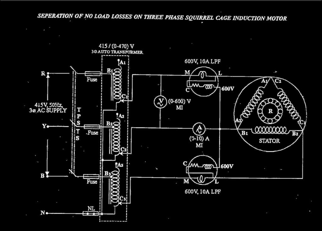
10 SEPARATION OF NO LOAD LOSSES OF THREE PHASE INDUCTION MOTOR AIM: To separate the no load losses of a 3 phase squirrel cage induction motor as iron losses and mechanical losses. NAME PLATE DETAILS: 3Ø Induction motor: HP: HP Speed: : RPM Voltage :..V Current :..A FUSE RATING: No load : 0% of rated current (full load current). APPARATUS REQUIRED: S.NO NAME OF THE APPARATUS Ammeter Voltmeter Wattmeter 3 Ф Auto transformer Tachometer Connecting wires RANGE TYPE QUANTITY (0-5) A (0-600) V 600Ω,5A 45/(0-470)V MI MI LPF Digital 2 As required PRECAUTIONS: i. The autotransformer should be kept in minimum voltage position. ii. The motor should not be loaded throughout the experiment. PROCEDURE: i. Connections should be made as per the circuit diagram. ii. Start the motor by giving three phase supply. iii. Vary the autotransformer till rated speed is attained and note the input power, voltage and current. iv. Repeat the same procedure for and tabulate the reading. 0
11 v. Find the stator copper loss and constant loss by respective formulas. vi. Draw the suitable graph to find the mechanical losses. vii. Obtain the core los by separating the mechanical loss from constant losses. GRAPH: The graph drawn between constant losses (watts) and input voltage(volts). MODEL CALCULATIONS:. Input power (W) =(W+W2)in watts 2. Stator copper loss =3I 2 R s in watts 3. Constant loss/phase (W c )= (W-3I 2 R s )/3 in watts 4 Core loss/phase (Wi)= (constant loss/phase)-mechanical loss TABULTAION: S.No V I W W 2 W Stator Cu Loss Constant Loss per Phase (W c ) Core Loss per Phase (W i ) RESULT: Thus the no load losses of 3-phase squirrel cage induction motor was separated as core losses and mechanical losses.

12 NO LOAD TEST 2
13 3
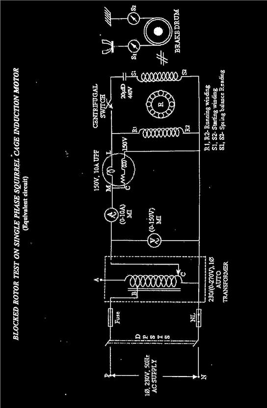
14 NO LOAD AND BLOCKED ROTOR TEST ON SINGLE PHASE INDUCTION MOTOR AIM: To draw the performance characteristics of a single phase induction motor by conducting the no-load and blocked rotor test. APPARATUS REQUIRED: S.No Name of Apparatus Range Type Qty. Voltmeter (0-300)V MI 2 Voltmeter (0-50)V MI 3 Ammeter (0-0)A MI 4 Ammeter (0-2)A MI 5 Wattmeter (330V,0A) UPF 6 Wattmeter (300V,5A) LPF 7 Connecting wires As reqd. FUSE RATING: 25% of..a=..a THEORY: A -Ф induction motor consists of stator,rotor and other associated parts.in the rotor of a single phase winding is provided.the windings of a - Ф winding(provided) are displaced in space by 20º.A single phase current is fed to the windings so that a resultant rotating magnetic flux is generated.the rotor starts rotating due to the induction effect produced due to the relative velocity between the rotor winding and the rotating flux. PRECAUTIONS: No load test: Initially TPST Switch is kept open. Autotransformer is kept at minimum potential position. The machines must be started on no load. BLOCKED ROTOR TEST: Initially the TPST Switch is kept open. Autotransformer is kept at minimum potential position. The machine must be started at full load (blocked rotor). PROCEDURE: NO LOAD TEST:. Connections are given as per the circuit diagram. 2. Precautions are observed and the motor is started at no load. 3. Autotransformer is varied to have a rated voltage applied. BLOCKED ROTOR TEST: 4
15 . Connections are given as per the circuit diagram. 2. Precautions are observed and motor is started on full load or blocked rotor position. 3. Autotransformer is varied to have rated current flowing in motor. 4. Meter readings are the noted. FORMULAE USED: R e =.6XR dc. No Load Test: cos Ф = W 0 /V 0 I 0 Iw = I 0 cosф Im = I 0 sin Ф R 0 = V 0 /I w X 0 = V 0 /I m 2. Blocked Rotor Test: o Z sc = V sc /I sc Ω o R sc = W sc /I 2 sc Ω o X sc = (Z 2 sc R 2 sc ) Ω TABULATION NO LOAD TEST S.No. Vo(volts) Io(amps) Wo(watts) m.f Observed Acual BLOCKED ROTOR TEST S.No. Vsc(volts) Isc(amps) Wsc(watts) m.f Observed Actual RESULT: Thus the no load and blocked rotor test on the single phase induction motor has been conducted and the equivalent circuit has been drawn. 5
DEPARTMENT OF ELECTRICAL & ELECTRONICS ENGINEERING 1
 DEPARTMENT OF ELECTRICAL & ELECTRONICS ENGINEERING 1 OC & SC TESTS ON SINGLE PHASE TRANSFORMER Circuit Diagram: (a) OC Test (b) SC Test Name Plate Details 1 Φ T/F: KVA = LV Voltage = HV Voltage = Frequency
STEADY STATE REACTANCE
 INDEX NO. : M-53 TECHNICAL MANUAL FOR STEADY STATE REACTANCE Manufactured by : PREMIER TRADING CORPORATION (An ISO 9001:2008 Certified Company) 212/1, Mansarover Civil Lines, MEERUT. Phone : 0121-2645457,
S J P N Trust's Hirasugar Institute of Technology, Nidasoshi.
 S J P N Trust's Hirasugar Institute of Technology, Nidasoshi. Inculcating Values, Promoting Prosperity Approved by AICTE New Delhi, Recognized by Govt. of Karnataka and Affiliated to VTU Belagavi. Tq:
Code No: R Set No. 1
 Code No: R05310204 Set No. 1 III B.Tech I Semester Regular Examinations, November 2007 ELECTRICAL MACHINES-III (Electrical & Electronic Engineering) Time: 3 hours Max Marks: 80 Answer any FIVE Questions
Electrical Machines (EE-343) For TE (ELECTRICAL)
 For TE (ELECTRICAL)") PRACTICALWORKBOOK Electrical Machines (EE-343) For TE (ELECTRICAL) Name: Roll Number: Year: Batch: Section: Semester: Department: N.E.D University of Engineering &Technology, Karachi Electrical Machines
PRACTICALWORKBOOK Electrical Machines (EE-343) For TE (ELECTRICAL) Name: Roll Number: Year: Batch: Section: Semester: Department: N.E.D University of Engineering &Technology, Karachi Electrical Machines
ELECTRICAL MACHINES LABORATORY 1 Lab Manual
 Channabasaveshwara Institute of Technology (An ISO 90:25 Certified Institution) NH 206 (B.H. Road), Gubbi, Tumkur 572 216. Karnataka. QMP 7.1 D/F Department of Electrical & Electronics Engineering ELECTRICAL
VALLIAMMAI ENGINEERING COLLEGE
 VALLIAMMAI ENGINEERING COLLEGE SRM Nagar, Kattankulathur 603 203 DEPARTMENT OF ELECTRONICS AND INSTRUMENTATION ENGINEERING QUESTION BANK IV SEMESTER EI6402 ELECTRICAL MACHINES Regulation 2013 Academic
Code No: R Set No. 1
 Code No: R05220204 Set No. 1 II B.Tech II Semester Supplimentary Examinations, Aug/Sep 2007 ELECTRICAL MACHINES-II (Electrical & Electronic Engineering) Time: 3 hours Max Marks: 80 Answer any FIVE Questions
BASIC ELECTRICAL AND ELCTRONICS ENGINEERING LABORATORY LAB MANUAL
 BASIC ELECTRICAL AND ELCTRONICS ENGINEERING LABORATORY LAB MANUAL Academic Year : 2017-2018 Course Code : AEE103 Regulations : IARE - R16 Semester : III Branch : (ME / AE) Department of Aeronautical Engineering
ELECTRICAL ENGINEERING LABORATORY MANUAL (NEE 151/251)
") ELECTRICAL ENGINEERING LABORATORY MANUAL (NEE 151/251) DEPARTMENTS OF ELECTRONICS & COMMUNICATION ENGINEERING/ ELECTRICAL ENGINEERING 27, Knowledge Park-III, Greater Noida, (U.P.) Phone: 0120-2323854-58
ELECTRICAL ENGINEERING LABORATORY MANUAL (NEE 151/251) DEPARTMENTS OF ELECTRONICS & COMMUNICATION ENGINEERING/ ELECTRICAL ENGINEERING 27, Knowledge Park-III, Greater Noida, (U.P.) Phone: 0120-2323854-58
INSTITUTE OF AERONAUTICAL ENGINEERING (Autonomous) Dundigal, Hyderabad ELECTRICAL AND ELECTRONICS ENGINEERING
 Dundigal, Hyderabad ELECTRICAL AND ELECTRONICS ENGINEERING") Course Name Course Code Class Branch INSTITUTE OF AERONAUTICAL ENGINEERING (Autonomous) Dundigal, Hyderabad - 500 043 ELECTRICAL AND ELECTRONICS ENGINEERING QUESTION BANK : ELECRICAL MACHINES I : A40212
Course Name Course Code Class Branch INSTITUTE OF AERONAUTICAL ENGINEERING (Autonomous) Dundigal, Hyderabad - 500 043 ELECTRICAL AND ELECTRONICS ENGINEERING QUESTION BANK : ELECRICAL MACHINES I : A40212
3. What is hysteresis loss? Also mention a method to minimize the loss. (N-11, N-12)
") DHANALAKSHMI COLLEGE OF ENGINEERING, CHENNAI DEPARTMENT OF ELECTRICAL AND ELECTRONICS ENGINEERING EE 6401 ELECTRICAL MACHINES I UNIT I : MAGNETIC CIRCUITS AND MAGNETIC MATERIALS Part A (2 Marks) 1. List
DHANALAKSHMI COLLEGE OF ENGINEERING, CHENNAI DEPARTMENT OF ELECTRICAL AND ELECTRONICS ENGINEERING EE 6401 ELECTRICAL MACHINES I UNIT I : MAGNETIC CIRCUITS AND MAGNETIC MATERIALS Part A (2 Marks) 1. List
EQUIVALENT CIRCUIT OF A SINGLE-PHASE TRANSFORMER
 Electrical Machines Lab Experiment-No. One Date: 15-11-2016 EQUIVALENT CIRCUIT OF A SINGLE-PHASE TRANSFORMER Aim: The determination of electrical equivalent circuit parameters of a single phase power transformer
SYNCHRONOUS MACHINES
 SYNCHRONOUS MACHINES The geometry of a synchronous machine is quite similar to that of the induction machine. The stator core and windings of a three-phase synchronous machine are practically identical
INSTITUTE OF AERONAUTICAL ENGINEERING (Autonomous) Dundigal, Hyderabad
 Dundigal, Hyderabad") INSTITUTE OF AERONAUTICAL ENGINEERING (Autonomous) Dundigal, Hyderabad - 00 0 ELECTRICAL AND ELECTRONICS ENGINEERING QUESTION BANK Course Name Course Code Class Branch : ELECRICAL MACHINES - II : A0 :
INSTITUTE OF AERONAUTICAL ENGINEERING (Autonomous) Dundigal, Hyderabad - 00 0 ELECTRICAL AND ELECTRONICS ENGINEERING QUESTION BANK Course Name Course Code Class Branch : ELECRICAL MACHINES - II : A0 :
1. (a) Determine the value of Resistance R and current in each branch when the total current taken by the curcuit in figure 1a is 6 Amps.
 Determine the value of Resistance R and current in each branch when the total current taken by the curcuit in figure 1a is 6 Amps.") Code No: 07A3EC01 Set No. 1 II B.Tech I Semester Regular Examinations, November 2008 ELECTRICAL AND ELECTRONICS ENGINEERING ( Common to Civil Engineering, Mechanical Engineering, Mechatronics, Production
Code No: 07A3EC01 Set No. 1 II B.Tech I Semester Regular Examinations, November 2008 ELECTRICAL AND ELECTRONICS ENGINEERING ( Common to Civil Engineering, Mechanical Engineering, Mechatronics, Production
SHRI RAMSWAROOP MEMORIAL COLLEGE OF ENGG. & MANAGEMENT
 SHRI RAMSWAROOP MEMORIAL COLLEGE OF ENGG. & MANAGEMENT B.Tech. [SEM I (CE,EC,EE,EN)] QUIZ TEST-3 (Session: 2012-13) Time: 1 Hour ELECTRICAL ENGINEERING Max. Marks: 30 (EEE-101) Roll No. Academic/26 Refer/WI/ACAD/18
Reg. No. : BASIC ELECTRICAL TECHNOLOGY (ELE 101)
") Department of Electrical and Electronics Engineering Reg. No. : MNIPL INSTITUTE OF TECHNOLOGY, MNIPL ( Constituent Institute of Manipal University, Manipal) FIRST SEMESTER B.E. DEGREE MKEUP EXMINTION (REVISED
Department of Electrical and Electronics Engineering Reg. No. : MNIPL INSTITUTE OF TECHNOLOGY, MNIPL ( Constituent Institute of Manipal University, Manipal) FIRST SEMESTER B.E. DEGREE MKEUP EXMINTION (REVISED
Aligarh College of Engineering & Technology (College Code: 109) Affiliated to UPTU, Approved by AICTE Electrical Engg.
 Affiliated to UPTU, Approved by AICTE Electrical Engg.") Aligarh College of Engineering & Technology (College Code: 19) Electrical Engg. (EE-11/21) Unit-I DC Network Theory 1. Distinguish the following terms: (a) Active and passive elements (b) Linearity and
Aligarh College of Engineering & Technology (College Code: 19) Electrical Engg. (EE-11/21) Unit-I DC Network Theory 1. Distinguish the following terms: (a) Active and passive elements (b) Linearity and
Placement Paper For Electrical
 Placement Paper For Electrical Q.1 The two windings of a transformer is (A) conductively linked. (B) inductively linked. (C) not linked at all. (D) electrically linked. Ans : B Q.2 A salient pole synchronous
CHAPTER 2 D-Q AXES FLUX MEASUREMENT IN SYNCHRONOUS MACHINES
 22 CHAPTER 2 D-Q AXES FLUX MEASUREMENT IN SYNCHRONOUS MACHINES 2.1 INTRODUCTION For the accurate analysis of synchronous machines using the two axis frame models, the d-axis and q-axis magnetic characteristics
Electrical Workstation Nvis 7089B
 All AC & DC Machines are optional Electrical Workstation offers an excellent approach to the teaching of Electrical Machines principles by introducing a unique modular designed control unit. It provides
REV NO EXPERIMENT NO 1 AIM: To perform open and short circuit tests on 1-phase transformer and to calculate efficiency. Apparatus required:
 KARNAL INSTITUTE OF TECHNOLOGY & MANAGEMENT KUNJPURA, KARNAL LAB MANUAL OF ------- SUBJECT CODE DATE OF ISSUE: SEMESTER: BRANCH: REV NO EXPERIMENT NO 1 AIM: To perform open and short circuit tests on 1-phase
Basic Electrical Engineering Lab Laboratory Manual
 DEV BHOOMI INSTITUTE OF TECHNOLOGY CHAKRATA ROAD,NAVGAOUN MANDUWALA,UTTARAKHAND Programs: B.TECH. (Electrical and Electronics Engineering) Basic Electrical Engineering Lab Laboratory Manual PREPARED BY
RAJKIYA ENGINEERING COLLEGE, KANNAUJ
 RAJKIYA ENGINEERING COLLEGE, KANNAUJ Tender No.: 23/EE/RECM/SPS/2016 Dated: 13.07.2016 due on 03.08.2016 by 1:30 pm Schedule 01 Laboratory Technical Specification / Model Details Qty. Electrical Complete
Basic Electrical & Electronics Engineering Laboratory
 Basic Electrical & Electronics Engineering Laboratory Dos and Don ts in Laboratory 1. Do not handle any equipment before reading the instructions /Instruction manuals. 2. Read carefully the power ratings
Generalized Theory Of Electrical Machines
 Essentials of Rotating Electrical Machines Generalized Theory Of Electrical Machines All electrical machines are variations on a common set of fundamental principles, which apply alike to dc and ac types,
THE UNIVERSITY OF BRITISH COLUMBIA. Department of Electrical and Computer Engineering. EECE 365: Applied Electronics and Electromechanics
 THE UNIVERSITY OF BRITISH COLUMBIA Department of Electrical and Computer Engineering EECE 365: Applied Electronics and Electromechanics Final Exam / Sample-Practice Exam Spring 2008 April 23 Topics Covered:
Electrical Workstation Nvis 7089A
 All AC & DC Machines are optional Electrical Workstation offers an excellent approach to the teaching of Electrical Machines principles by introducing a unique modular designed control unit. It provides
Manuals. Basic Electrical Engineering BE-104
 Manuals Basic Electrical Engineering BE-104 S.NO. EXPERIMENT NAME DATE 1 Measurement of power & power factor in a single phase AC circuit using three Ammeter Method 2 Measurement of active & reactive power
Geethanjali College of Engineering & Technology
 ELECTRICAL TECHNOLOGY LAB Geethanjali College of Engineering & Technology ELECTRICAL TECHNOLOGY LAB MANUAL II-B.Tech II-SEMESTER(ECE),2015-2016 Prepared By B.RAMESH BABU, M.Pradeep manjul khare pooja raani
MAHARASHTRA STATE BOARD OF TECHNICAL EDUCATION
 Important Instructions to examiners: 1) The answers should be examined by key words and not as word-to-word as given in the model answer scheme. 2) The model answer and the answer written by candidate
Module 1. Introduction. Version 2 EE IIT, Kharagpur
 Module 1 Introduction Lesson 1 Introducing the Course on Basic Electrical Contents 1 Introducing the course (Lesson-1) 4 Introduction... 4 Module-1 Introduction... 4 Module-2 D.C. circuits.. 4 Module-3
SIR C R REDDY COLLEGE OF ENGINEERING EEE Department, ELURU.
 EEE3110-ELECTRICAL MEASUREMENTS LAB III/IV EEE, I Semester SIR C R REDDY COLLEGE OF ENGINEERING EEE Department, ELURU. NAME:. REGD.NO: SECTION:..Academic Year:.. SIR.C.R.REDDY COLLEGE OF ENGINEERING
ELECTRICAL MACHINE LAB. MANUAL : EM II/1
 EE 59 ELECTRICL MCHINE LB. MNUL EXPERIMENT NO : EM II/ TITLE Different Method of Starting Of Three-Phase Squirrel Cage Induction Motor and Their Comparison. [DOL, uto-transformer, Star-Delta] OBJECTIE
The synchronous machine as a component in the electric power system
 1 The synchronous machine as a component in the electric power system dφ e = dt 2 lectricity generation The synchronous machine is used to convert the energy from a primary energy resource (such as water,
PART A. 1. List the types of DC Motors. Give any difference between them. BTL 1 Remembering
 UNIT I DC MACHINES Three phase circuits, a review. Construction of DC machines Theory of operation of DC generators Characteristics of DC generators Operating principle of DC motors Types of DC motors
INSTITUTE OF AERONAUTICAL ENGINEERING (Autonomous) Dundigal, Hyderabad
 Dundigal, Hyderabad") INSTITUTE OF AERONAUTICAL ENGINEERING (Autonomous) Dundigal, Hyderabad - 00 03 ELECTRICAL AND ELECTRONICS ENGINEERING ASSIGNMENT Course Name : ELECRICAL MACHINES - II Course Code : A0 Class : II B.TECH-II
INSTITUTE OF AERONAUTICAL ENGINEERING (Autonomous) Dundigal, Hyderabad - 00 03 ELECTRICAL AND ELECTRONICS ENGINEERING ASSIGNMENT Course Name : ELECRICAL MACHINES - II Course Code : A0 Class : II B.TECH-II
1. Explain in detail the constructional details and working of DC motor.
 DHANALAKSHMI SRINIVASAN INSTITUTE OF RESEARCH AND TECHNOLOGY, PERAMBALUR DEPT OF ECE EC6352-ELECTRICAL ENGINEERING AND INSTRUMENTATION UNIT 1 PART B 1. Explain in detail the constructional details and
MAHARASHTRA STATE BOARD OF TECHNICAL EDUCATION
 Important Instructions to examiners: 1) The answers should be examined by key words and not as word-to-word as given in the model answer scheme. 2) The model answer and the answer written by candidate
Experiment No. Experiments for First Year Electrical Engg Lab
 Experiment No im: To determine Regulation and Efficiency of a single phase transformer using open circuit (O.C.) and short circuit (S.C.) tests pparatus: - Single phase transformer Single phase dimmer
Objective: Study of self-excitation characteristics of an induction machine.
 Objective: Study of self-excitation characteristics of an induction machine. Theory: The increasing importance of fuel saving has been responsible for the revival of interest in so-called alternative source
Hours / 100 Marks Seat No.
 17404 21314 3 Hours / 100 Seat No. Instructions (1) All Questions are Compulsory. (2) Answer each next main Question on a new page. (3) Illustrate your answers with neat sketches wherever necessary. (4)
ELECTRICAL TECHNOLOGY
 ELECTRICAL TECHNOLOGY Subject Code: (EC303ES) Regulations : R6 JNTUH Class :II Year B.Tech ECE I Semester Department of Electronics and communication Engineering BHARAT INSTITUTE OF ENGINEERING AND TECHNOLOGY
1. A battery has an emf of 12.9 volts and supplies a current of 3.5 A. What is the resistance of the circuit?
 1. A battery has an emf of 12.9 volts and supplies a current of 3.5 A. What is the resistance of the circuit? (a) 3.5 Ω (b) 16.4 Ω (c) 3.69 Ω (d) 45.15 Ω 2. Sign convention used for potential is: (a) Rise
 VIDYARTHIPLUS - ANNA UNIVERSITY ONLINE STUDENTS COMMUNITY UNIT 1 DC MACHINES PART A 1. State Faraday s law of Electro magnetic induction and Lenz law. 2. Mention the following functions in DC Machine (i)
Three-Phase Induction Motors. By Sintayehu Challa ECEg332:-Electrical Machine I
 Three-Phase Induction Motors 1 2 3 Classification of AC Machines 1. According to the type of current Single Phase and Three phase 2. According to Speed Constant Speed, Variable Speed and Adjustable Speed
Synchronous Machines Study Material
 Synchronous machines: The machines generating alternating emf from the mechanical input are called alternators or synchronous generators. They are also known as AC generators. All modern power stations
UNIVERSITY OF TECHNOLOGY By: Fadhil A. Hasan ELECTRICAL MACHINES
 UNIVERSITY OF TECHNOLOGY DEPARTMENT OF ELECTRICAL ENGINEERING Year: Second 2016-2017 By: Fadhil A. Hasan ELECTRICAL MACHINES І Module-II: AC Transformers o Single phase transformers o Three-phase transformers
Module 7. Transformer. Version 2 EE IIT, Kharagpur
 Module 7 Transformer Lesson 28 Problem solving on Transformers Contents 28 Problem solving on Transformer (Lesson-28) 4 28.1 Introduction. 4 28.2 Problems on 2 winding single phase transformers. 4 28.3
Hours / 100 Marks Seat No.
 17415 15162 3 Hours / 100 Seat No. Instructions (1) All Questions are Compulsory. (2) Answer each next main Question on a new page. (3) Illustrate your answers with neat sketches wherever necessary. (4)
CHAPTER 5 SYNCHRONOUS GENERATORS
 CHAPTER 5 SYNCHRONOUS GENERATORS Summary: 1. Synchronous Generator Construction 2. The Speed of Rotation of a Synchronous Generator 3. The Internal Generated Voltage of a Synchronous Generator 4. The Equivalent
INSTITUTE OF AERONAUTICAL ENGINEERING (AUTONOMOUS) Dundigal, Hyderabad
 Dundigal, Hyderabad") INSTITUTE OF AERONAUTICAL ENGINEERING (AUTONOMOUS) Dundigal, Hyderabad - 500 043 CIVIL ENGINEERING ASSIGNMENT Name : Electrical and Electronics Engineering Code : A30203 Class : II B. Tech I Semester Branch
INSTITUTE OF AERONAUTICAL ENGINEERING (AUTONOMOUS) Dundigal, Hyderabad - 500 043 CIVIL ENGINEERING ASSIGNMENT Name : Electrical and Electronics Engineering Code : A30203 Class : II B. Tech I Semester Branch
Transformer & Induction M/C
 UNIT- 2 SINGLE-PHASE TRANSFORMERS 1. Draw equivalent circuit of a single phase transformer referring the primary side quantities to secondary and explain? (July/Aug - 2012) (Dec 2012) (June/July 2014)
GATE SOLVED PAPER - EE
 YEAR 03 Q. Leakage flux in an induction motor is (A) flux that leaks through the machine (B) flux that links both stator and rotor windings (C) flux that links none of the windings (D) flux that links
PESIT Bangalore South Campus Hosur road, 1km before Electronic City, Bengaluru -100 Department of Electronics & Communication Engineering
 INTERNAL ASSESSMENT TEST 3 Date : 15/11/16 Marks: 0 Subject & Code: BASIC ELECTRICAL ENGINEERING -15ELE15 Sec : F,G,H,I,J,K Name of faculty : Mrs.Hema, Mrs.Dhanashree, Mr Nagendra, Mr.Prashanth Time :
CHAPTER 3 EQUIVALENT CIRCUIT AND TWO AXIS MODEL OF DOUBLE WINDING INDUCTION MOTOR
 35 CHAPTER 3 EQUIVALENT CIRCUIT AND TWO AXIS MODEL OF DOUBLE WINDING INDUCTION MOTOR 3.1 INTRODUCTION DWIM consists of two windings on the same stator core and a squirrel cage rotor. One set of winding
CHAPTER 2. Transformers. Dr Gamal Sowilam
 CHAPTER Transformers Dr Gamal Sowilam Introduction A transformer is a static machine. It is not an energy conversion device, it is indispensable in many energy conversion systems. A transformer essentially
MAHARASHTRA STATE BOARD OF TECHNICAL EDUCATION
 Important Instructions to examiners: 1. The answers should be examined by key words and not as word-to-word as given in the model answer scheme. 2. The model answer and the answer written by candidate
MEHRAN UNIVERSITY OF ENGINEERING & TECHNOLOGY, JAMSHORO
 DEPARTMENT OF MEHRAN UNIVERSITY OF ENGINEERING & TECHNOLOGY, JAMSHORO Name Roll No. Subject Teacher MEHRAN UNIVERSITY OF ENGINEERING & TECHNOLOGY, JAMSHORO 1 Name:. Roll No: Score: Signature of Lab Tutor:
Introduction : Design detailed: DC Machines Calculation of Armature main Dimensions and flux for pole. Design of Armature Winding & Core.
 Introduction : Design detailed: DC Machines Calculation of Armature main Dimensions and flux for pole. Design of Armature Winding & Core. Design of Shunt Field & Series Field Windings. Design detailed:
MAHARASHTRA STATE BOARD OF TECHNICAL EDUCATION
 Important Instructions to examiners: 1) The answers should be examined by key words and not as word-to-word as given in the model answer scheme. 2) The model answer and the answer written by candidate
ELG2336 Introduction to Electric Machines
 ELG2336 Introduction to Electric Machines Magnetic Circuits DC Machine Shunt: Speed control Series: High torque Permanent magnet: Efficient AC Machine Synchronous: Constant speed Induction machine: Cheap
Open Circuit (OC) and Short Circuit (SC) Tests on Single Phase Transformer
 and Short Circuit (SC) Tests on Single Phase Transformer") Open Circuit (OC) and Short Circuit (SC) Tests on Single Phase Transformer 1 Aim To obtain the equivalent circuit parameters from OC and SC tests, and to estimate efficiency & regulation at various loads.
Open Circuit (OC) and Short Circuit (SC) Tests on Single Phase Transformer 1 Aim To obtain the equivalent circuit parameters from OC and SC tests, and to estimate efficiency & regulation at various loads.
IOCL Electrical Engineering Technical Paper
 IOCL Electrical Engineering Technical Paper 1. Which one of the following statements is NOT TRUE for a continuous time causal and stable LTI system? (A) All the poles of the system must lie on the left
Unit 3 Magnetism...21 Introduction The Natural Magnet Magnetic Polarities Magnetic Compass...21
 Chapter 1 Electrical Fundamentals Unit 1 Matter...3 Introduction...3 1.1 Matter...3 1.2 Atomic Theory...3 1.3 Law of Electrical Charges...4 1.4 Law of Atomic Charges...4 Negative Atomic Charge...4 Positive
LECTURE NOTES ON ELECTRICAL MACHINE-II. Subject Code-PCEL4302
 LECTURE NOTES ON ELECTRICAL MACHINE-II Subject Code-PCEL4302 For B.Tech 5 th Semester Electrical Engineering MODULE-III SYNERGY INSTITUTE OF ENGINEERING AND TECHNOLOGY Department of Electrical Engineering
Transformers. gpmacademics.weebly.com
 TRANSFORMERS Syllabus: Principles of operation, Constructional Details, Losses and efficiency, Regulation of Transformer, Testing: OC & SC test. TRANSFORMER: It is a static device which transfers electric
1. SQUIRREL CAGE AC MOTOR. NO LOAD TEST
 1. SQUIRREL CAGE AC MOTOR. NO LOAD TEST 1.1 INTRODUCTION. DESCRIPTION OF THE EXPERIMENT The three-phase induction motor carries a three-phase winding on its stator. The rotor is either a wound type or
CHIEF ENGINEER REG III/2 MARINE ELECTROTECHNOLOGY
 CHIEF ENGINEER REG III/2 MARINE ELECTROTECHNOLOGY LIST OF TOPICS 1 Electric Circuit Principles 2 Electronic Circuit Principles 3 Generation 4 Distribution 5 Utilisation The expected learning outcome is
EE 350: Electric Machinery Fundamentals
 EE 350: Electric Machinery Fundamentals Lecture Schedule See Time Table Course Type, Semester Fundamental Engineering, Fifth Credit Hours Three + One Pre-requisite Physics Instructor Dr. Muhammad Asghar
ELECTRICAL TECHNOLOGY LAB LAB MANUAL I, II SEMESTER
 s ELECTRICAL TECHNOLOGY LAB LAB MANUAL I, II SEMESTER www.uptudunia.com E-Mail:- uptudunia@gmail.com CONTENTS Sr.No TITLE Page No. 1. TO VERIFY KVL AND KCL LAW 3-6 2. TO VERIFY THEVENIN S THEOREM 7-9 3.
148 Electric Machines
 148 Electric Machines 3.1 The emf per turn for a single-phase 2200/220- V, 50-Hz transformer is approximately 12 V. Calculate (a) the number of primary and secondary turns, and (b) the net cross-sectional
SHRI RAMSWAROOP MEMORIAL COLLEGE OF ENGG. & MANAGEMENT B.Tech. [SEM I (EE, EN, EC, CE)] QUIZ TEST-3 (Session: ) Time: 1 Hour ELECTRICAL ENGINEE
![SHRI RAMSWAROOP MEMORIAL COLLEGE OF ENGG. & MANAGEMENT B.Tech. [SEM I (EE, EN, EC, CE)] QUIZ TEST-3 (Session: ) Time: 1 Hour ELECTRICAL ENGINEE](/thumbs/94/118213481.jpg "SHRI RAMSWAROOP MEMORIAL COLLEGE OF ENGG. & MANAGEMENT B.Tech. [SEM I (EE, EN, EC, CE)] QUIZ TEST-3 (Session: ) Time: 1 Hour ELECTRICAL ENGINEE") SHRI RAMSWAROOP MEMORIAL COLLEGE OF ENGG. & MANAGEMENT B.Tech. [SEM I (EE, EN, EC, CE)] QUIZ TEST-3 (Session: 2014-15) Time: 1 Hour ELECTRICAL ENGINEERING Max. Marks: 30 (NEE-101) Roll No. Academic/26
SHRI RAMSWAROOP MEMORIAL COLLEGE OF ENGG. & MANAGEMENT B.Tech. [SEM I (EE, EN, EC, CE)] QUIZ TEST-3 (Session: 2014-15) Time: 1 Hour ELECTRICAL ENGINEERING Max. Marks: 30 (NEE-101) Roll No. Academic/26
Anna University of Technology Madurai. Alagar kovil road, Madurai REGULATIONS -2010
 Alagar kovil road, Madurai-6 00. REGULATIONS -00 III Semester B. E. Electronics and Communication Engineering 044EC307 Digital Electronics Lab Requirement for a batch of 30 students Sl. No Name of the
ELECTRIC DRIVE LAB Laboratory Manual
 DEV BHOOMI INSTITUTE OF TECHNOLOGY CHAKRATA ROAD, NAVGAOUN MANDUWALA, UTTARAKHAND Programs: B.TECH. (Electrical and Electronics Engineering) ELECTRIC DRIVE LAB Laboratory Manual PREPARED BY ASHISH KUKRETI,
CERTIFICATES OF COMPETENCY IN THE MERCHANT NAVY MARINE ENGINEER OFFICER
 CERTIFICATES OF COMPETENCY IN THE MERCHANT NAVY MARINE ENGINEER OFFICER EXAMINATIONS ADMINISTERED BY THE SCOTTISH QUALIFICATIONS AUTHORITY ON BEHALF OF THE MARITIME AND COASTGUARD AGENCY STCW 78 as amended
INSTITUTE OF AERONAUTICAL ENGINEERING (Autonomous) Dundigal, Hyderabad
 Dundigal, Hyderabad") INSTITUTE OF AERONAUTICAL ENGINEERING (Autonomous) Dundigal, Hyderabad -00 03 ELECTRCIAL AND ELECTRONICS ENGINEERING TUTORIAL QUESTION BANK Course Name Course Code Class Branch : DC MACHINES AND TRANSFORMERS
INSTITUTE OF AERONAUTICAL ENGINEERING (Autonomous) Dundigal, Hyderabad -00 03 ELECTRCIAL AND ELECTRONICS ENGINEERING TUTORIAL QUESTION BANK Course Name Course Code Class Branch : DC MACHINES AND TRANSFORMERS
Experiment 3. Performance of an induction motor drive under V/f and rotor flux oriented controllers.
 University of New South Wales School of Electrical Engineering & Telecommunications ELEC4613 - ELECTRIC DRIVE SYSTEMS Experiment 3. Performance of an induction motor drive under V/f and rotor flux oriented
Preface...x Chapter 1 Electrical Fundamentals
 Preface...x Chapter 1 Electrical Fundamentals Unit 1 Matter...3 Introduction...3 1.1 Matter...3 1.2 Atomic Theory...3 1.3 Law of Electrical Charges...4 1.4 Law of Atomic Charges...5 Negative Atomic Charge...5
PRACTICAL WORK BOOK. Basic Electrical & Electronics Engineering BE-104
 PRACTICAL WORK BOOK Basic Electrical & Electronics Engineering BE-104 Name: Enrollment No: Branch: Semester: Batch: Institute: Department of Electrical Engineering I N D E X S.NO. EXPERIMENT NAME DATE
INSTITUTE OF AERONAUTICAL ENGINEERING (Autonomous) Dundigal, Hyderabad
 Dundigal, Hyderabad") I INSTITUTE OF AERONAUTICAL ENGINEERING (Autonomous) Dundigal, Hyderabad-500043 CIVIL ENGINEERING TUTORIAL QUESTION BANK Course Name : BASIC ELECTRICAL AND ELECTRONICS ENGINEERING Course Code : AEE018
I INSTITUTE OF AERONAUTICAL ENGINEERING (Autonomous) Dundigal, Hyderabad-500043 CIVIL ENGINEERING TUTORIAL QUESTION BANK Course Name : BASIC ELECTRICAL AND ELECTRONICS ENGINEERING Course Code : AEE018
86 chapter 2 Transformers
 86 chapter 2 Transformers Wb 1.2x10 3 0 1/60 2/60 3/60 4/60 5/60 6/60 t (sec) 1.2x10 3 FIGURE P2.2 2.3 A single-phase transformer has 800 turns on the primary winding and 400 turns on the secondary winding.
VALLIAMMAI ENGINEERING COLLEGE BE8161-BASIC ELECTRICAL, ELECTRONICS AND INSTRUMENTATION ENGINEERING LABORATORY LABORATORY MANUAL
 VALLIAMMAI ENGINEERING COLLEGE SRM NAGAR, KATTANKULATHUR 603203 DEPARTMENT OF MECHANICAL ENGINEERING BE8161-BASIC ELECTRICAL, ELECTRONICS AND INSTRUMENTATION ENGINEERING LABORATORY LABORATORY MANUAL II
ELECTRICAL TECHNOLOGY LAB MANUAL
 ELECTRICAL TECHNOLOGY LAB MANUAL For II-B.Tech (ECE) Department of EEE 1 Aurora s Technological and Research Institute Parvathapur, Uppal, Hyderabad-500 039 2 LABORATORY PRACTICE I HEAR, I FORGET I SEE,
Ac fundamentals and AC CIRCUITS. Q1. Explain and derive an expression for generation of AC quantity.
 Ac fundamentals and AC CIRCUITS Q1. Explain and derive an expression for generation of AC quantity. According to Faradays law of electromagnetic induction when a conductor is moving within a magnetic field,
Generator Advanced Concepts
 Generator Advanced Concepts Common Topics, The Practical Side Machine Output Voltage Equation Pitch Harmonics Circulating Currents when Paralleling Reactances and Time Constants Three Generator Curves
Spring 2000 EE361: MIDTERM EXAM 1
 NAME: STUDENT NUMBER: Spring 2000 EE361: MIDTERM EXAM 1 This exam is open book and closed notes. Assume f=60 hz and use the constant µ o =4π 10-7 wherever necessary. Be sure to show all work clearly. 1.
COLLEGE OF ENGINEERING DEPARTMENT OF ELECTRICAL AND ELECTRONICS ENGINEERING ACADEMIC YEAR / EVEN SEMESTER QUESTION BANK
 KINGS COLLEGE OF ENGINEERING DEPARTMENT OF ELECTRICAL AND ELECTRONICS ENGINEERING ACADEMIC YEAR 2010-2011 / EVEN SEMESTER QUESTION BANK SUBJECT CODE & NAME: EE 1352 - ELECTRICAL MACHINE DESIGN YEAR / SEM
ELECTRICAL ENGINEERING ESE TOPIC WISE OBJECTIVE SOLVED PAPER-II
 ELECTRICAL ENGINEERING ESE TOPIC WISE OBJECTIVE SOLVED PAPER-II From (1992 2017) Office : F-126, (Lower Basement), Katwaria Sarai, New Delhi-110016 Phone : 011-26522064 Mobile : 8130909220, 9711853908
MAHARASHTRA STATE BOARD OF TECHNICAL EDUCATION
 Important Instructions to examiners: 1) The answers should be examined by key words and not as word-to-word as given in the model answer scheme. 2) The model answer and the answer written by candidate
Practical Transformer on Load
 Practical Transformer on Load We now consider the deviations from the last two ideality conditions : 1. The resistance of its windings is zero. 2. There is no leakage flux. The effects of these deviations
CHAPTER 3 IMPROVEMENT OF LOAD POWER FACTOR USING FACTS CONTROLLERS
 40 CHAPTER 3 IMPROVEMENT OF LOAD POWER FACTOR USING FACTS CONTROLLERS 3.1 INTRODUCTION The low power factor effects on transmission line, switchgear, transformers etc. It is observed that if the power
PCEL-4302 ELECTRICAL MACHINES-II
 PCEL-4302 ELECTRICAL MACHINES-II 5 TH SEMESTER B.TECH IN ELECTRICAL ENGINEERING SYLLABUS Disclaimer This document does not claim any originality and cannot be used as a substitute for prescribed textbooks.
PROBLEMS on Transformers
 PROBLEMS on Transformers (A) Simple Problems 1. A single-phase, 250-kVA, 11-kV/415-V, 50-Hz transformer has 80 turns on the secondary. Calculate (a) the approximate values of the primary and secondary
3.1.Introduction. Synchronous Machines
 3.1.Introduction Synchronous Machines A synchronous machine is an ac rotating machine whose speed under steady state condition is proportional to the frequency of the current in its armature. The magnetic
EE 340L EXPERIMENT # 3 SYNCHRONOUS GENERATORS
 EE 340L EXPERIMENT # 3 SYNCHRONOUS GENERATORS A. EQUIVALENT CIRCUIT PARAMETERS A.1. OPEN CIRCUIT TEST (a) Mechanically couple the generator with a shunt-excited DC motor as shown in figure 4(a). (b) With
Downloaded From All JNTU World
 Code: 9A02403 GENERATION OF ELECTRIC POWER 1 Discuss the advantages and disadvantages of a nuclear plant as compared to other conventional power plants. 2 Explain about: (a) Solar distillation. (b) Solar
Code No. : 09(1) Roll No...
 Roll No...") This question paper contains 6 printed pages ] Code No. : 09(1) Roll No..... O(CCEM)9 ELECTRICAL ENGINEERING Paper: I Time Allowed: 3 hours I l Maximum Marks : 300 Note: (i) Answers must be written in
This question paper contains 6 printed pages ] Code No. : 09(1) Roll No..... O(CCEM)9 ELECTRICAL ENGINEERING Paper: I Time Allowed: 3 hours I l Maximum Marks : 300 Note: (i) Answers must be written in
BASIC ELECTRICAL AND ELCTRONICS ENGINEERING LABORATORY LAB MANUAL
 BASIC ELECTRICAL AND ELCTRONICS ENGINEERING LABORATORY LAB MANUAL Academic Year : 208-209 Course Code Regulations Semester Branch : AEE03 : IARE - R6 : III : (ME / AE) INSTITUTE OF AERONAUTICAL ENGINEERING