SIR C R REDDY COLLEGE OF ENGINEERING EEE Department, ELURU.
|
|
|
- Britney Bridges
- 6 years ago
- Views:
Transcription


1 EEE3110-ELECTRICAL MEASUREMENTS LAB III/IV EEE, I Semester SIR C R REDDY COLLEGE OF ENGINEERING EEE Department, ELURU. NAME:. REGD.NO: SECTION:..Academic Year:..
2
3
4

5 SIR.C.R.REDDY COLLEGE OF ENGINEERING ELURU DEPARTMENT OF ELECTRICAL AND ELECTRONICS ENGINEERING CERTIFICATE This is to certify that this is the bonafide record of the work done in ELECTRICAL MEASUREMENTS Laboratory by Mr/Ms bearing Regd. No..of B.Tech course during Total number of experiments held Total number of experiments done LAB-IN-CHARGE HEAD OF THE DEPARTMENT
6
7 List of Experiments S.No. Name of the experiment 1. Calibration of UPF wattmeter using phantom loading. 2. Calibration of energy meter using phantom loading. 3. Measurement of three-phase power using two-wattmeter method. 4. Measurement of power and power factor using 3 Ammeter method and 3 Voltmeter method. 5. Measurement of inductance by Anderson s bridge. 6. Measurement of capacitance by Schering bridge. 7. Measurement of capacitance by De-Sauty bridge. 8. Measurement of three-phase active and reactive power by one-wattmeter method. 9. Measurement of frequency by Wein s bridge. 10. Measurement of resistance by Wheatstone bridge. 11. Measurement of frequency using CRO.
8
9 INDEX Sl.No. NAME OF THE EXPERIMENT Date Page No. Valued Grade
10
11
12
13 CALIBRATION OF UPF WATTMETER USING PHANTOM LOADING Ex. No: Date: AIM: To calibrate UPF wattmeter using Phantom loading. APPARATUS: S. No Apparatus Range Type Quantity 1 Ammeter MI 1 2 Voltmeter MI ØAuto Transformer MI 1 4 Wattmeter Iron Core 1 5 Step-down Transformer Iron Core 6 Rheostat WW 1 7 Connecting wires PVC Insulated -- THEORY: 1
14 TABULAR FORM: S.NO V(V) I(A) W(W) P=VI(W) %Error %Correction
15 PROCEDURE: 1. Connect the circuit as shown in the diagram. 2. Close the DPST switch of high voltage supply when 1-ØAuto Transformer at zero output. 3. Apply rated voltage to pressure coil of wattmeter(c,v) using 1-ØAuto Transformer. 4. Keep rheostat in cut in position and then apply low voltage to current coil of wattmeter (m,l) using step down transformer by closing DPST switch. 5. Vary the rheostat from 1A to rated current. 6. For each step note down the all meter readings. 7. Bring the back rheostat and 1-ØAuto Transformer to original position and open the DPST switches. CALCULATIONS: % Error = ((W-P)/P) *100 %Correction = ((P-W)/P)*100 Model Graph: PRECAUTIONS: RESULT: 3
16 4
17 CALIBRATION OF ENERGY METER USING PHANTOM LOADING METHOD Ex. No: Date: AIM: To calibrate the energy meter using phantom loading method. APPARATUS: S. No Apparatus Type Range Quantity 1 Single phase auto transformer Iron core 1 2 Single Phase Step Down Transformer Iron core 3 Ammeter MI 1 4 Voltmeter MI 1 5 Wattmeter EDM 1 6 Energy Meter Induction Type 1 7 Stop Watch Digital 1 8 Connecting Wires PVC Insulated THEORY: When the current ratting of a meter under test is high a test with actual loading arrangements would involve a considerable waste of power. In order to avoid this "phantom" or 'fictitious" loading is done. Phantom loading consists of supplying the pressure circuit from a circuit required normal voltage, and the current circuit from a separate low voltage supply. it is possible to circulate the rated current through the current circuit with a low voltage supply as the impedance of this circuit is very low. With this arrangement the total power supplied for the test is that due to the small pressure coil current at normal voltage, plus that due to the current circuit current supplied at low voltage. The total power, therefore, required for testing the meter with phantom loading is comparatively very small. 5
18 TABULARFORM: S. No Voltage In Volts Current In Amps Power In Watts Time Taken For 5 Revolutions Made By Disc % Of Error % Of Correction 6
19 PROCEDURE: 1. The connections are made as shown in the circuit diagram (1) 2. Keep the single phase auto transformer at zero output position and rheostat at Cut in position and then close DPST switches of both HV and LV supply. 3. By varying the single phase auto transformer apply rated voltage. 4. Now by varying the rheostat in steps of 1A to up to rated current, for each step note down the ammeter and wattmeter readings and time taken for 5 revolutions of energy meter disc. 5. Now, bring back the rheostat to cut in position and auto transformer to zero Position and open both DPST switches. CREEP TEST: 1. The connections are made as shown in the circuit diagram (2). 2. Only give supply to shunt magnet of energy meter as shown in figure. 3. If the disc of energy meter rotates it is having creeping, otherwise no error. SPECIMEN CALCULATIONS: Energy meter constant = 1200 revolutions/kwh. NO.OF Units recorded in energy meter for 5 revolutions Er = (1/1200) X 5 KWH. Energy actually consumed for 5 revolutions Ea = (W/1000) X (t/ (60x60)) KWH. Percentage Error = (Er - Ea)/Ea x100. Percentage correction = (Ea - Er)/Ea x100. 7
20 Model Graphs: 8
21 PRECAUTIONS: RESULT: 9
22 10
23 MEASUREMENT OF THREE-PHASE POWER USING TWO WATTMETER METHOD. Ex. No: Date: AIM: To measure the 3-phase power using two wattmeter method in a balanced a.c circuit. APPRATUS: S. No Apparatus Range Type Quantity 1 Ammeter MI 1 2 Voltmeter MI 1 3 Wattmeter EDW Ø load Resistive 5 3-Ø Auto Transformer 6 Connecting wires PVC Insulated THEORY: 11
24 TABULARFORM: S.NO VL IL W1 W2 P= W1+W2 Pa= 3VLILcosØ (V) (A) (W) (W) (W) (W) 12
25 PROCEDURE: 1. Make the connections as per the circuit diagram. 2. Close the supply (TPST) switch, when 3-Ø auto transformer at zero output position. 3. The load is applied in steps and for each step each meter readings are noted. 4. Repeat the step 3 until the rated current of load is reached. 5. Load is removed in steps and bring back 3-Ø auto transformer to initial position and TPST Switch is opened. PRECAUTIONS: RESULT: 13
26 14
27 MEASUREMENT OF POWER AND POWER FACTOR IN 1-Ø AC CIRCUIT BY 3-AMMETER METHOD AND 3-VOLTMETER METHOD Ex. No: Date: AIM: To Measure Power and Power Factor by 3-Ammeter and 3-Voltmeter Method. APPARATUS: S. No Apparatus Type Range Quantity 1. 1-ØAuto transformer Iron Core 1 2. Transformer Iron Core 1 3. Rheostat Wire wound 1 4. Voltmeter MI 1 5. Ammeter MI 1 6. Ammeter MI 1 7. Ammeter MI 1 8. Rheostat Wire wound 1 9. Voltmeter MI Voltmeter MI Choke Coil Iron core Connecting Wires PVC Insulated THEORY: 3-Ammeter Method Power factor (cos ) = (I3 2 -(I1 2 +I2 2 ))/2I1I2 Power consumed by the inductor (PL) = (I3 2 -(I1 2 +I2 2 ))/2R 15
28 TABULAR FORM For 3-Ammeter Method: S. No Voltmeter (v) Ammeter reading(a) I1 (A) I2 (A) I3 (A) Resistance (Ω) R=V/I Power factor cos Power consumed by individual load (W) 16

 PL = (I3")
)/2I1I2 3-Voltmeter Method: Power factor")

29 From phasor diagram, we have: I3 2 =I1 2 +I2 2 +2I1I2cos But, I1=V/R I3 2 =I1 2 +I2 2 +2V/RI2cos Hence the power, PL=VI2 cos is given by; PL=R/2( I3 2 -I1 2 -I2 2 ) PL = (I3 2 -(I1 2 +I2 2 ))/2R Cos = (I3 2 -(I1 2 +I2 2 ))/2I1I2 3-Voltmeter Method: Power factor (cos = (v 2 -(v1 2 +v2 2 ))/ (2v1v2) Power consumed by the induction = (v 2 -(v1 2 +v2 2 ))/ (2R) 17
30 TABULAR FORM for 3-Voltmeter Method: S. No. Ammeter reading(a) Voltmeter reading(v) V 1 (V) V 2 (V) V 3 (V) Power factor cos Power consumed by individual load (W) 18
31 From the phasor diagram we have V 2 =V1 2 +V2 2 +2V1V2cos =V1 2 +V2 2 +2V1(IR)cos =V1 2 +V2 2 +2R(V1Icos ) From the phasor diagram we have, V 2 =V1 2 +V2 2 +2V1V2cos =V1 2 +V2 2 +2V1(IR)cos =V1 2 +V2 2 +2R(V1Icos ) V 2 =V1 2 +V2 2 +2PR Since power in the inductive circuit, P=V1Icos = V 2 -V1 2 -V2 2 /2R P = (v 2 -(v1 2 +v2 2 ))/ (2R) cos = V 2 -V1 2 -V2 2 /2V1V2 = v 2 -(v1 2 +v2 2 )/ 2v1v2 PROCEDURE for 3-Ammeter Method: 1) Circuit is constructed as per circuit diagram. 2) The moving contact of the rheostat is kept at maximum resistance position and auto transformer is at zero position. 3) Now the single phase a.c supply is given to the circuit by closing DPST Switch. 4) The rated current is made pass through the transformer in steps by varying the auto transformer. 5) The readings of voltmeter and ammeter are tabulated and bring back auto transformer to zero output and open DPST Switch. PROCEDURE for 3-Volmeter Method: 1) Circuit is constructed as per circuit diagram. 2) The moving contact of the rheostat is kept at maximum resistance position and autotransformer is at zero position. 3) Now the single phase a.c supply is given to the circuit by closing DPST Switch. 4) Rated voltage is applied across the choke in steps by varying the auto-transformer. 5) The readings of voltmeter and ammeter are tabulated and bring back auto transformer to zero output and open DPST Switch. 19
32 Model Calculations: 3-Ammeter Method Power factor (cos ) = (I3 2 -(I1 2 +I2 2 ))/2I1I2 Power consumed = (I3 2 -(I1 2 +I2 2 ))/2R 3-Voltmeter Method Power factor (cos = (v 2 -(v1 2 +v2 2 ))/ (2v1v2) Power consumed by the induction = (v 2 -(v1 2 +v2 2 ))/ (2R) 20
33 PRECAUTIONS: RESULT: 21
34 22
35 MEASUREMENT OF INDUCTANCE BY ANDERSON S BRIDGE Ex. No: Date: AIM: To measure the unknown inductance by using Anderson s bridge. APPARATUS: S. No Apparatus Range Type Quantity 1 Bridge Panel Multimeter ---- Digital 1 3 Step Down Transformer Iron Core 1 4 Inductance DIB 1 5 Patch Cards and Wires PVC Insulated THEORY: 23
36 Bridge Balance Equation & Vector Diagram: 24
37 PROCEDURE: 1. The circuit is designed on the bridge panel as shown in the circuit diagram. 2. Switch on the power supply. 3. Now vary the variable resistors (r1,r) until the value in the multimeter shows zero value, which is the balanced condition of the bridge. 4. The value of variable resistors at balancing condition of bridge is noted. 5. The power supply is switched off. 6. Compare the measured value with calibrated value. PRECAUTIONS: 1. Don t touch bare conductors when supply is ON. 2. Wear shoes in laboratory to avoid electric shocks. 3. Switch off all measuring devices when not in use. RESULT: 25
38 26
39 MEASUREMENT OF CAPACITANCE BY SCHERING BRIDGE Ex. No: Date: AIM: To Determine the unknown capacitance by using Schering bridge. APPARATUS: S. No Apparatus Range Type Quantity 1 Bridge Panel Multimeter ---- Digital 1 3 Step Down Transformer Iron Core 1 4 Capacitor DCB 2 5 Patch Cards and Wires PVC Insulated THEORY: 27
40 Bridge Balance Condition & Vector Diagram: 28
41 PROCEDURE: 1. The circuit is designed on the bridge panel as shown in circuit diagram. 2. Switch on the power supply. 3. Now vary the variable capacitor and Resistor (C4, R4) until the value in the multimeter shows zero voltage value i.e. the bridge is balanced. 4. The value of variable capacitor and Resistor at balancing condition of bridge is noted. 5. The power supply is switched off. 6. Compare the measured value with calibrated value. PRECAUTIONS: RESULT: 29
42 30
43 MEASUREMENT OF CAPACITANCE BY USING DE-SAUTY BRIDGE Ex. No: Date: AIM: To measure the value of capacitance of a given capacitor by using De-Sauty bridge. APPARATUS: S. No Apparatus Range Type Quantity 1 Bridge Panel Multimeter ---- Digital 1 3 Step Down Transformer Iron Core 1 4 Capacitor DCB 1 5 Patch Cards and Wires PVC Insulated THEORY: 31
44 Bridge Balance Condition and Vector Diagram: 32
45 PROCEDURE: 1. The circuit is designed on the bridge panel as shown in the circuit diagram. 2. Switch on the power supply. 3. Now varying the variable resistor (R4) in steps until the value in the multimeter shows zero volts i.e. bridge is balanced. 4. The value of variable resistor at balancing condition of bridge is noted. 5. The power supply is switched off. 6. Compare measuring values with calibrated values. PRECAUTIONS: RESULT: 33
46 34
47 MEASUREMENT OF ACTIVE AND REACTIVE POWER USING ONE WATTMETER METHOD Ex. No: Date: AIM: To measure active and reactive power in three phase balanced load by one wattmeter method. APPARATUS: S. No Apparatus Type Range Quantity 1 3-Φ Auto Transformer Iron Core 1 2 Ammeter MI 1 3 Voltmeter MI 1 4 Wattmeter EDW 2 5 Load Box Inductive 1 6 Connecting Wires PVC Insulated THEORY: Power in 3 phase system may be measured by using 1. Three single phase wattmeter - This method is used for a star connected, 4 wire systems, balanced or unbalanced load. 2. Two 1 phase wattmeter - This method is suitable for 3 phase, 3 wire system and widely used. It is applicable to both delta and star system, balanced or unbalanced load. 3. One single phase wattmeter - This method is applicable to balanced load only. 4. One 3 phase wattmeter - 3 phase wattmeter consists of two or three wattmeter elements mounted together in one case with moving coils mounted on the same spindle One wattmeter method for measurement of active power is for 3 phase balanced load only. The current coil of the wattmeter is connected in one of the lines and one end of pressure coil is connected to the same line. The readings are taken by connecting other terminal of pressure coil alternately to other 2 lines. The active power is Ö3 times the wattmeter reading. 35
48 TABULARFORM: S. No Voltage Current Wattmeter-P VARMeter-Q 3-Φ Active Power 3-Φ Reactive Power (V) (A) (W) (VAR) P(KW) Q(KVAR) 36
49 It is often convenient and even essential that reactive power be measured. For example in load monitoring, such a measurement gives the operator the information of the nature of load. Also the reactive power serves as a check on power factor measurements, since ratio of reactive and active power is tan f = Q/P Where Q & P are the reactive and active power respectively One wattmeter method for measurement of reactive power is for 3 phase balanced load only. The current coil of the wattmeter is connected in one of the lines. The pressure coil is connected across two lines. The reactive power is 3 times the wattmeter reading. PROCEDURE: 1. Connect the circuit as per circuit diagram. 2. Keep the inductive load at cut out position & 3-Φ Auto Transformer at zero output position and close TPST switch. 3. Vary 3-Φ Auto Transformer up to rated voltage (say 415V) 4. Now gradually move the load in steps (say 1A to 10A) for each step note down the ammeter, voltmeter & wattmeter reading. 5. Remove the load, bring back the 3-Φ Auto Transformer to zero output & open the TPST switch PRECAUTIONS: 1. Connection must be in tight 2. Where the shoes in laboratory 3. Inductive load box produce lot of noise and vibrations, so place the load in proper position where floor is uniform. 4. Please check the auto transformer is at zero output position at closing and opening TPST Switch. RESULT: 37
50 38
51 WEIN S BRIDGE Ex. No: Date: AIM: To measure frequency by using wein s bridge. APPARTUS: S. No Apparatus Range Type Quantity 1 Bridge Panel Multimeter ---- Digital 1 3 Function Generator 1 4 Patch Cards and Wires PVC Insulated ---- THEORY: 39
52 Bridge Balance Condition & Vector Diagram: 40
53 PROCEDURE: 1. The circuit in the panel is designed as shown in the circuit diagram. 2. Switch on the function generator with some unknown frequency. 3. Vary the variable resistors (R1 & R2) simultaneously, up to multimeter shows zero Voltage i.e, bridge balance condition. 4. Measure the variable resistors valves at this point. 5. Turn off the power supply. PRECAUTIONS: 1. Don t touch bare conductors when supply is ON. 2. Wear shoes in laboratory to avoid electric shocks. 3. Switch off all measuring devices when not in use. RESULT: 41
54 42
55 MEASUREMENT OF RESISTANCE BY WHEATSTONE BRIDGE Ex. No: Date: AIM: To determine the unknown resistance by Wheatstone bridge. APPARATUS: S. No Apparatus Range Type Quantity 1 Bridge Panel Multimeter ---- Digital 1 3 Step Down Transformer Iron Core 1 4 Patch Cards and Wires PVC Insulated ---- THEORY: 43
56 Bridge Balance Condition and Vector Diagram: 44
57 PROCEDURE: 1. The circuit is designed on the bridge panel as shown in circuit diagram. 2. Switch on the power supply. 3. Now vary the Variable resistance(s) until the value in the multimeter shows zero voltage value i.e., the bridge is balanced. 4. The value of variable resistance at balancing condition of bridge is noted. 5. The power supply is switched off. PRECAUTIONS: 1. Don t touch bare conductors when supply is ON. 2. Wear shoes in laboratory to avoid electric shocks. 3. Switch off all measuring devices when not in use. 4. Check for proper polarity of meters. RESULT: 45
58 46
59 MEASUREMENT OF FREQUENCY USING CRO Ex. No: Date: AIM: To obtain Lissajous figures and to determine the ratio s of the frequencies by using two function generators. APPARATUS: S. No Apparatus Range Type Quantity 1. Function generators 2 2. Cathode ray oscilloscope(cro) 1 3. CRO Probes and Patch Cards ---- PVC Insulated ---- THEORY: 47
60 TABULARFORM: S. No Vertical Shape Of The Figure No.Of Tangent Points Frequency Input Frequency Fy(Hz) Horizontal Vertical Ratio Fy: Fx 48
61 PROCEDURE: 1. The circuit is wired as shown in figure. One signal generator is connected to the vertical(y) input and the other to the horizontal(x) input of the oscilloscope. The CRO and the two generators are switched ON. The X-generator is set at 100Hz and the Y- generator dial is used to see the stationary ellipse on the screen. The controls of CRO are adjusted to get the ellipse of satisfactory size. 2. Leaving the horizontal(x) input at 100Hz and assuming it to be the standard, the vertical input frequency may be varied from 100 to 900Hz to see the Lissajou s figures. Any number of figures can be obtained in this manner and a few of such configurations is as shown below and frequencies ratios are determined. 49
62 MODEL CALCULATION: The ratio of the two frequencies is given by: fy / fx = (Number of times tangent touches top or bottom)/ (Number of times tangent touches either side) = (number of horizontal tangents)/ (number of vertical tangents) fy =frequency of signal applied to Y plates fx = frequency of signal applied to X plates 50
63 PRECAUTIONS: RESULT: 1. The ratios of the frequencies of the two Signals are calculated by forming Lissajou s figures. 2. Calculated Vertical frequencies are fy= Hz. 3. Given horizontal frequency fx= Hz. 51
64 52
65 CIRCUIT DIAGRAMS 53
66 54
67 55

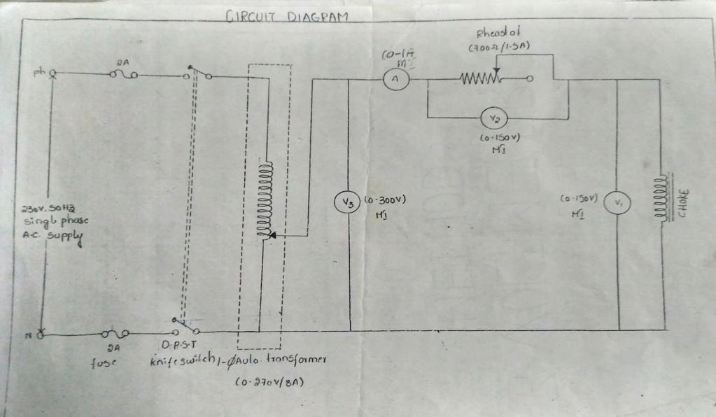
68 MEASUREMENT OF POWER IN AC CIRCUIT BY 3-AMMETER METHOD MEASUREMENT OF POWER IN AC CIRCUIT BY 3-AMMETER METHOD 56
69 v Electrical measurements lab manual Measurement of active and reactive power by 1-Wattmeter method 57
Bhoj Reddy Engineering College for Women, Hyderabad Department of Electronics and Communication Engineering Electrical and Electronics Instrumentation
 Bhoj Reddy Engineering College for Women, Hyderabad Department of Electronics and Communication Engineering Electrical and Electronics Instrumentation Academic Year: 2016-17 III B Tech II Semester Branch:
DEPARTMENT OF ELECTRICAL ENGINEERING
 DEPARTMENT OF ELECTRICAL ENGINEERING LAB MANUAL SUBJECT: EMI B.TECH -3 RD SEM KCT COLLEGE OF ENGG & TECH FATEHGARH PUNJAB TECHNICAL UNIVERSITY Prepared by:- Er. Prince Munjal (AP) B.Tech (EE) M.Tech( EE)
TITLE: Introduction to various Basic Instruments of Electrical Science
 EXPERIMENT NO : 1 TITLE: Introduction to various Basic Instruments of Electrical Science OBJECTIVE: Introduction to various Supply Systems, Ammeter, Voltmeter, Wattmeter, Energy meter, Tachometer, Rheostat,
Dhanalakshmi Srinivasan Institute of Technology, Samayapuram, Trichy. Cycle 2 EE6512 Electrical Machines II Lab Manual
 Cycle 2 EE652 Electrical Machines II Lab Manual CIRCUIT DIAGRAM FOR SLIP TEST 80V DC SUPPLY 350Ω, 2 A 3 Point Starter L F A NAME PLATE DETAILS: 3Ф alternator DC shunt motor FUSE RATING: Volts: Volts: 25%
ELECTRICAL MEASUREMENTS
 R10 Set No: 1 1. a) Derive the expression for torque equation for a moving iron attraction type instrument and comment up on the nature of scale [8] b) Define the terms current sensitivity, voltage sensitivity
VALLIAMMAI ENGINEERING COLLEGE
 VALLIAMMAI ENGINEERING COLLEGE SRM NAGAR, KATTANKULATHUR 603203 DEPARTMENT OF ELECTRICAL AND ELECTRONICS ENGINEERING EE8261-ELECTRIC CIRCUITS LABORATORY LABORATORY MANUAL 1 ST YEAR EEE (REGULATION 2017)
SIDDHARTH GROUP OF INSTITUTIONS :: PUTTUR (AUTONOMOUS) Siddharth Nagar, Narayanavanam Road QUESTION BANK (DESCRIPTIVE)
 Siddharth Nagar, Narayanavanam Road QUESTION BANK (DESCRIPTIVE)") SIDDHARTH GROUP OF INSTITUTIONS :: PUTTUR (AUTONOMOUS) Siddharth Nagar, Narayanavanam Road 517583 QUESTION BANK (DESCRIPTIVE) Suject : Electrical & Electronic Measurements(16EE224) Year & Sem: III-B.Tech
SIDDHARTH GROUP OF INSTITUTIONS :: PUTTUR (AUTONOMOUS) Siddharth Nagar, Narayanavanam Road 517583 QUESTION BANK (DESCRIPTIVE) Suject : Electrical & Electronic Measurements(16EE224) Year & Sem: III-B.Tech
ELECTRICAL ENGINEERING LABORATORY MANUAL (NEE 151/251)
") ELECTRICAL ENGINEERING LABORATORY MANUAL (NEE 151/251) DEPARTMENTS OF ELECTRONICS & COMMUNICATION ENGINEERING/ ELECTRICAL ENGINEERING 27, Knowledge Park-III, Greater Noida, (U.P.) Phone: 0120-2323854-58
ELECTRICAL ENGINEERING LABORATORY MANUAL (NEE 151/251) DEPARTMENTS OF ELECTRONICS & COMMUNICATION ENGINEERING/ ELECTRICAL ENGINEERING 27, Knowledge Park-III, Greater Noida, (U.P.) Phone: 0120-2323854-58
Code No: RR Set No. 1
 Code No: RR310202 Set No. 1 III B.Tech I Semester Regular Examinations, November 2006 ELECTRICAL MEASUREMENTS (Electrical & Electronic Engineering) Time: 3 hours Max Marks: 80 Answer any FIVE Questions
Electrical Machines (EE-343) For TE (ELECTRICAL)
 For TE (ELECTRICAL)") PRACTICALWORKBOOK Electrical Machines (EE-343) For TE (ELECTRICAL) Name: Roll Number: Year: Batch: Section: Semester: Department: N.E.D University of Engineering &Technology, Karachi Electrical Machines
PRACTICALWORKBOOK Electrical Machines (EE-343) For TE (ELECTRICAL) Name: Roll Number: Year: Batch: Section: Semester: Department: N.E.D University of Engineering &Technology, Karachi Electrical Machines
Geethanjali College of Engineering & Technology
 ELECTRICAL TECHNOLOGY LAB Geethanjali College of Engineering & Technology ELECTRICAL TECHNOLOGY LAB MANUAL II-B.Tech II-SEMESTER(ECE),2015-2016 Prepared By B.RAMESH BABU, M.Pradeep manjul khare pooja raani
UNIT II MEASUREMENT OF POWER AND ENERGY PART-A
 UNIT II MEASUREMENT OF POWER AND ENERGY PART-A 1. A 3 500 V motor load has a pf of 0.4. Two wattmeters connected to measure the input. They show the input to be 30 kw. Find the reading of each instrument
Manuals. Basic Electrical Engineering BE-104
 Manuals Basic Electrical Engineering BE-104 S.NO. EXPERIMENT NAME DATE 1 Measurement of power & power factor in a single phase AC circuit using three Ammeter Method 2 Measurement of active & reactive power
Basic Electrical Engineering Lab Laboratory Manual
 DEV BHOOMI INSTITUTE OF TECHNOLOGY CHAKRATA ROAD,NAVGAOUN MANDUWALA,UTTARAKHAND Programs: B.TECH. (Electrical and Electronics Engineering) Basic Electrical Engineering Lab Laboratory Manual PREPARED BY
DEPARTMENT OF ELECTRICAL AND ELECTRONICS ENGINEERING EE6211-ELECTRIC CIRCUITS LABORATORY LABORATORY MANUAL 1ST YEAR EEE (REGULATION 2013)
") DEPARTMENT OF ELECTRICAL AND ELECTRONICS ENGINEERING EE62-ELECTRIC CIRCUITS LABORATORY LABORATORY MANUAL ST YEAR EEE (REGULATION 203) EE62 ELECTRIC CIRCUITS LABORATORY LTPC0032 LIST OF EXPERIMENTS. Experimental
DEPARTMENT OF ELECTRICAL AND ELECTRONICS ENGINEERING EE62-ELECTRIC CIRCUITS LABORATORY LABORATORY MANUAL ST YEAR EEE (REGULATION 203) EE62 ELECTRIC CIRCUITS LABORATORY LTPC0032 LIST OF EXPERIMENTS. Experimental
DEPARTMENT OF ELECTRICAL & ELECTRONICS ENGINEERING 1
 DEPARTMENT OF ELECTRICAL & ELECTRONICS ENGINEERING 1 OC & SC TESTS ON SINGLE PHASE TRANSFORMER Circuit Diagram: (a) OC Test (b) SC Test Name Plate Details 1 Φ T/F: KVA = LV Voltage = HV Voltage = Frequency
PRINCIPLES OF MEASUREMENT AND INSTRUMENTATION & INSTRUMENTS
 Contents i SYLLABUS osmania university UNIT - I PRINCIPLES OF MEASUREMENT AND INSTRUMENTATION & INSTRUMENTS Principles of Measurement and Instrumentation and Instruments : Objectives of Measurements, Analog
KKR & KSR INSTITUTE OF TECHNOLOGY & SCIENCES. Handouts
 KKR & KSR INSTITUTE OF TECHNOLOGY & SCIENCES (Approved by AICTE, New Delhi, Affiliated to JNTU Kakinada, Accredited by NAAC with A Grade) DEPARTMENT OF ELECTRICAL AND ELECTRONICS ENGINEERING Handouts Subject:
(Approved by AICTE & Affiliated to Calicut University) DEPARTMENT OF ELECTRICAL & ELECTRONICS ENGINEERING : ELECTRICAL MEASUREMENTS AND
 DEPARTMENT OF ELECTRICAL & ELECTRONICS ENGINEERING : ELECTRICAL MEASUREMENTS AND") (Approved by AICTE & Affiliated to Calicut University) DEPARTMENT OF ELECTRICAL & ELECTRONICS ENGINEERING ELECTRICAL MEASUREMENTS AND INSTRUMENTATION LAB CLASS SEMESTER SUBJECT CODE SUBJECT : II YEAR (EEE)
(Approved by AICTE & Affiliated to Calicut University) DEPARTMENT OF ELECTRICAL & ELECTRONICS ENGINEERING ELECTRICAL MEASUREMENTS AND INSTRUMENTATION LAB CLASS SEMESTER SUBJECT CODE SUBJECT : II YEAR (EEE)
ELECTRICAL MACHINES LABORATORY 1 Lab Manual
 Channabasaveshwara Institute of Technology (An ISO 90:25 Certified Institution) NH 206 (B.H. Road), Gubbi, Tumkur 572 216. Karnataka. QMP 7.1 D/F Department of Electrical & Electronics Engineering ELECTRICAL
Anna University of Technology Madurai. Alagar kovil road, Madurai REGULATIONS -2010
 Alagar kovil road, Madurai-6 00. REGULATIONS -00 III Semester B. E. Electronics and Communication Engineering 044EC307 Digital Electronics Lab Requirement for a batch of 30 students Sl. No Name of the
BASIC ELECTRICAL WORKSHOP LAB (2039)
") BASIC ELECTRICAL WORKSHOP LAB (2039) DEPARTMENT OF ELECTRICAL & ELECTRONICS ENGINEERING TOPICS PAGE NO. INTRODUCTION AND SAFETY PRECAUTIONS. 01 ELECTRICAL SYMBOLS. 02 LINE TESTER. 07 SWITCHES. 09 BASIC
BASIC ELECTRICAL WORKSHOP LAB (2039) DEPARTMENT OF ELECTRICAL & ELECTRONICS ENGINEERING TOPICS PAGE NO. INTRODUCTION AND SAFETY PRECAUTIONS. 01 ELECTRICAL SYMBOLS. 02 LINE TESTER. 07 SWITCHES. 09 BASIC
Jawaharlal Nehru Engineering College, Aurangabad.
 Jawaharlal Nehru Engineering College, Aurangabad. Laboratory Manual ELECTRICAL MEASUREMENT & TEACHNIQUES [EMT] For Second Year (EEP) Students Manual made by- Prof. J.S.Solanke FORWARD It is my great pleasure
SHRI RAMSWAROOP MEMORIAL COLLEGE OF ENGG. & MANAGEMENT
 SHRI RAMSWAROOP MEMORIAL COLLEGE OF ENGG. & MANAGEMENT B.Tech. [SEM I (CE,EC,EE,EN)] QUIZ TEST-3 (Session: 2012-13) Time: 1 Hour ELECTRICAL ENGINEERING Max. Marks: 30 (EEE-101) Roll No. Academic/26 Refer/WI/ACAD/18
UNIVERSITY OF TECHNOLOGY, JAMAICA SCHOOL OF ENGENEERING. Electrical Engineering Science. Laboratory Manual
 UNIVERSITY OF TECHNOLOGY, JAMAICA SCHOOL OF ENGENEERING Electrical Engineering Science Laboratory Manual Table of Contents Experiment #1 OHM S LAW... 3 Experiment # 2 SERIES AND PARALLEL CIRCUITS... 8
DIPLOMA COURSE IN ELECTRONICS AND COMMUNICATION ENGINEERING
 Department of Technical Education DIPLOMA COURSE IN ELECTRONICS AND COMMUNICATION ENGINEERING Third Semester ELECTRONIC MEASUREMENTS AND INSTRUMENTATION Contact Hours/Week : 04 Contact Hours/Semester :
Note: 1. All the students must strictly follow all the safety precautions. 2. In case of any question or concern, please contact LAB INSTRUCTOR or TA.
 UNIVERSITY OF WATERLOO ELECTRICAL & COMPUTER ENGINEERING DEPARTMENT FALL 2006 E&CE 261: Energy Systems and Components EXPERIMENT 1: THREE-PHASE SYSTEMS Contents covered in this laboratory exercise: 1.
PRACTICAL WORK BOOK. Basic Electrical & Electronics Engineering BE-104
 PRACTICAL WORK BOOK Basic Electrical & Electronics Engineering BE-104 Name: Enrollment No: Branch: Semester: Batch: Institute: Department of Electrical Engineering I N D E X S.NO. EXPERIMENT NAME DATE
INSTITUTE OF AERONAUTICAL ENGINEERING (Autonomous)
") INSTITUTE OF AERONAUTICAL ENGINEERING (Autonomous) Dundigal, Hyderabad - 500 04 ELECTRICAL AND ELECTRONICS ENGINEERING COURSE DESCRIPTION FORM Course Title Course Code Regulation Course Structure Course
INSTITUTE OF AERONAUTICAL ENGINEERING (Autonomous) Dundigal, Hyderabad - 500 04 ELECTRICAL AND ELECTRONICS ENGINEERING COURSE DESCRIPTION FORM Course Title Course Code Regulation Course Structure Course
PART A. 1. List the types of DC Motors. Give any difference between them. BTL 1 Remembering
 UNIT I DC MACHINES Three phase circuits, a review. Construction of DC machines Theory of operation of DC generators Characteristics of DC generators Operating principle of DC motors Types of DC motors
Kuestion Electrical and Electronic Measurements
 Kuestion Electrical and Electronic Measurements www.kreatryx.com Contents Manual for Kuestion... 2 Type : Error Analysis... 3 Type 2: Enhancement of Instrument Range... 5 Type 3:PMMC... 6 Type 4: Moving
Aligarh College of Engineering & Technology (College Code: 109) Affiliated to UPTU, Approved by AICTE Electrical Engg.
 Affiliated to UPTU, Approved by AICTE Electrical Engg.") Aligarh College of Engineering & Technology (College Code: 19) Electrical Engg. (EE-11/21) Unit-I DC Network Theory 1. Distinguish the following terms: (a) Active and passive elements (b) Linearity and
Aligarh College of Engineering & Technology (College Code: 19) Electrical Engg. (EE-11/21) Unit-I DC Network Theory 1. Distinguish the following terms: (a) Active and passive elements (b) Linearity and
Contents. Core information about Unit
 1 Contents Core information about Unit UEENEEH114A - Troubleshoot resonance circuits......3 UEENEEG102A Solve problems in low voltage AC circuits...5 TextBook...7 Topics and material Week 1...9 2 Core
Chapter 30 Inductance, Electromagnetic. Copyright 2009 Pearson Education, Inc.
 Chapter 30 Inductance, Electromagnetic Oscillations, and AC Circuits 30-7 AC Circuits with AC Source Resistors, capacitors, and inductors have different phase relationships between current and voltage
ECE 215 Lecture 8 Date:
 ECE 215 Lecture 8 Date: 28.08.2017 Phase Shifter, AC bridge AC Circuits: Steady State Analysis Phase Shifter the circuit current I leads the applied voltage by some phase angle θ, where 0 < θ < 90 ο depending
S J P N Trust's Hirasugar Institute of Technology, Nidasoshi.
 S J P N Trust's Hirasugar Institute of Technology, Nidasoshi. Inculcating Values, Promoting Prosperity Approved by AICTE New Delhi, Recognized by Govt. of Karnataka and Affiliated to VTU Belagavi. Tq:
INSTITUTE OF AERONAUTICAL ENGINEERING (Autonomous) Dundigal, Hyderabad ELECTRICAL AND ELECTRONICS ENGINEERING
 Dundigal, Hyderabad ELECTRICAL AND ELECTRONICS ENGINEERING") INSTITUTE OF AERONAUTICAL ENGINEERING (Autonomous) Dundigal, Hyderabad - 500 043 ELECTRICAL AND ELECTRONICS ENGINEERING QUESTION BANK Course Name : Electrical and Electronics Instrumentation Course Code
INSTITUTE OF AERONAUTICAL ENGINEERING (Autonomous) Dundigal, Hyderabad - 500 043 ELECTRICAL AND ELECTRONICS ENGINEERING QUESTION BANK Course Name : Electrical and Electronics Instrumentation Course Code
SINGLE PHASE CURRENT SOURCE INVERTER (C.S.I)
") Power Electronics Laboratory SINGLE PHASE CURRENT SOURCE INVERTER (C.S.I) OBJECT: To study the gate firing pulses. To observe and measure the voltages across the Thyristors and across the Load for a current
Power Electronics Laboratory SINGLE PHASE CURRENT SOURCE INVERTER (C.S.I) OBJECT: To study the gate firing pulses. To observe and measure the voltages across the Thyristors and across the Load for a current
BASIC ELECTRICAL AND ELCTRONICS ENGINEERING LABORATORY LAB MANUAL
 BASIC ELECTRICAL AND ELCTRONICS ENGINEERING LABORATORY LAB MANUAL Academic Year : 2017-2018 Course Code : AEE103 Regulations : IARE - R16 Semester : III Branch : (ME / AE) Department of Aeronautical Engineering
 EI6301 - ELECTRICAL MEASUREMENTS UNIT I MEASUREMENT OF VOLTAGE AND CURRENT PART-A 1. A PMMC instrument has a 0.12T magnetic flux density in its air gaps. The coil dimensions are D = 1.5 cm and l =2.25
INSTITUTE OF AERONAUTICAL ENGINEERING (AUTONOMOUS) Dundigal, Hyderabad
 Dundigal, Hyderabad") INSTITUTE OF AERONAUTICAL ENGINEERING (AUTONOMOUS) Dundigal, Hyderabad - 500 043 CIVIL ENGINEERING ASSIGNMENT Name : Electrical and Electronics Engineering Code : A30203 Class : II B. Tech I Semester Branch
INSTITUTE OF AERONAUTICAL ENGINEERING (AUTONOMOUS) Dundigal, Hyderabad - 500 043 CIVIL ENGINEERING ASSIGNMENT Name : Electrical and Electronics Engineering Code : A30203 Class : II B. Tech I Semester Branch
Electronic Measurements & Instrumentation. 1. Draw the Maxwell s Bridge Circuit and derives the expression for the unknown element at balance?
 UNIT -6 1. Draw the Maxwell s Bridge Circuit and derives the expression for the unknown element at balance? Ans: Maxwell's bridge, shown in Fig. 1.1, measures an unknown inductance in of standard arm offers
Experiment No. Experiments for First Year Electrical Engg Lab
 Experiment No im: To determine Regulation and Efficiency of a single phase transformer using open circuit (O.C.) and short circuit (S.C.) tests pparatus: - Single phase transformer Single phase dimmer
ANALOG ELECTRONIC CIRCUITS LABORATORY MANUAL (CODE: EEE - 228)
") ANALOG ELECTRONIC CIRCUITS LABORATORY MANUAL (CODE: EEE - 228) DEPARTMENT OF ELECTRONICS & COMMUNICATION ENGINEERING ANIL NEERUKONDA INSTITUTE OF TECHNOLOGY & SCIENCES (Affiliated to AU, Approved by AICTE
ANALOG ELECTRONIC CIRCUITS LABORATORY MANUAL (CODE: EEE - 228) DEPARTMENT OF ELECTRONICS & COMMUNICATION ENGINEERING ANIL NEERUKONDA INSTITUTE OF TECHNOLOGY & SCIENCES (Affiliated to AU, Approved by AICTE
Module 1. Introduction. Version 2 EE IIT, Kharagpur
 Module 1 Introduction Lesson 1 Introducing the Course on Basic Electrical Contents 1 Introducing the course (Lesson-1) 4 Introduction... 4 Module-1 Introduction... 4 Module-2 D.C. circuits.. 4 Module-3
University of Jordan School of Engineering Electrical Engineering Department. EE 219 Electrical Circuits Lab
 University of Jordan School of Engineering Electrical Engineering Department EE 219 Electrical Circuits Lab EXPERIMENT 4 TRANSIENT ANALYSIS Prepared by: Dr. Mohammed Hawa EXPERIMENT 4 TRANSIENT ANALYSIS
Question Paper Code : B.E./B.Tech. DEGREE EXAMINATION, NOVEMBER/DECEMBER Third Semester. Electrical and Electronics Engineering
 Question Paper Code : 31391 B.E./B.Tech. DEGREE EXAMINATION, NOVEMBER/DECEMBER 2013. Third Semester Electrical and Electronics Engineering EE 2201/EE 33/EI 1202/10133 EE 302/080280016 MEASUREMENTS AND
ECE215 Lecture 7 Date:
 Lecture 7 Date: 29.08.2016 AC Circuits: Impedance and Admittance, Kirchoff s Laws, Phase Shifter, AC bridge Impedance and Admittance we know: we express Ohm s law in phasor form: where Z is a frequency-dependent
ELECTRICAL CIRCUITS LABORATORY MANUAL (II SEMESTER)
") ELECTRICAL CIRCUITS LABORATORY MANUAL (II SEMESTER) LIST OF EXPERIMENTS. Verification of Ohm s laws and Kirchhoff s laws. 2. Verification of Thevenin s and Norton s Theorem. 3. Verification of Superposition
ELECTRICAL CIRCUITS LABORATORY MANUAL (II SEMESTER) LIST OF EXPERIMENTS. Verification of Ohm s laws and Kirchhoff s laws. 2. Verification of Thevenin s and Norton s Theorem. 3. Verification of Superposition
MEASUREMENT AND INSTRUMENTATION QUESTION BANK UNIT I INTRODUCTION. Part A
 MEASUREMENT AND INSTRUMENTATION QUESTION BANK UNIT I INTRODUCTION Part A 1. Define Standard deviation. 2. Why calibration of instrument is important? 3. What are the different calibration methodologies?
Synchronous Machines Study Material
 Synchronous machines: The machines generating alternating emf from the mechanical input are called alternators or synchronous generators. They are also known as AC generators. All modern power stations
Basic Electrical & Electronics Engineering Laboratory
 Basic Electrical & Electronics Engineering Laboratory Dos and Don ts in Laboratory 1. Do not handle any equipment before reading the instructions /Instruction manuals. 2. Read carefully the power ratings
Measurement of Resistance and Potentiometers
 Electrical Measurements International Program Department of Electrical Engineering UNIVERSITAS INDONESIA Measurement of Resistance and Potentiometers Jahroo Renardi Lecturer : Ir. Chairul Hudaya, ST, M.Eng.,
MAHARASHTRA STATE BOARD OF TECHNICAL EDUCATION
 Subject Code: 17322 (EEM) Model Answers Page No: 1 of 16 Important Instructions to examiners: 1) The answers should be examined by key words and not as word-to-word as given in the model answer scheme.
Dev Bhoomi Institute Of Technology Department of Electronics and Communication Engineering PRACTICAL INSTRUCTION SHEET
 Dev Bhoomi Institute Of Technology Department of Electronics and Communication Engineering PRACTICAL INSTRUCTION SHEET LABORATORY MANUAL EXPERIMENT NO. ISSUE NO. : ISSUE DATE: REV. NO. : REV. DATE : PAGE:
 DEPARTMENT OF ELECTRICAL AND ELECTRONICS ENGINEERING EE6511 CONTROL AND INSTRUMENTATION LABORATORY MANUAL 2016-2017 ODD SEMESTER INDEX Sl. No. Date of Expt. Name of the Experiment Page No. Marks Staff
Table of Contents...2. About the Tutorial...6. Audience...6. Prerequisites...6. Copyright & Disclaimer EMI INTRODUCTION Voltmeter...
 1 Table of Contents Table of Contents...2 About the Tutorial...6 Audience...6 Prerequisites...6 Copyright & Disclaimer...6 1. EMI INTRODUCTION... 7 Voltmeter...7 Ammeter...8 Ohmmeter...8 Multimeter...9
ELECTRICAL MEASUREMENTS
 ELECTRICAL MEASUREMENTS GEETHANJALI COLLEGE OF ENGINEERING AND TECHNOLOGY DEPARTMENT OF EEE Name of the Subject : Electrical Measurements JNTU CODE : 56009 Programme : UG / PG Branch: Electrical & Electronics
University of Jordan School of Engineering Electrical Engineering Department. EE 219 Electrical Circuits Lab
 University of Jordan School of Engineering Electrical Engineering Department EE 219 Electrical Circuits Lab EXPERIMENT 7 RESONANCE Prepared by: Dr. Mohammed Hawa EXPERIMENT 7 RESONANCE OBJECTIVE This experiment
Goals. Introduction. To understand the use of root mean square (rms) voltages and currents.
 voltages and currents.") Lab 10. AC Circuits Goals To show that AC voltages cannot generally be added without accounting for their phase relationships. That is, one must account for how they vary in time with respect to one another.
Lab 10. AC Circuits Goals To show that AC voltages cannot generally be added without accounting for their phase relationships. That is, one must account for how they vary in time with respect to one another.
MAHARASHTRA STATE BOARD OF TECHNICAL EDUCATION (Autonomous) (ISO/IEC Certified) SUMMER 14 EXAMINATION Model Answer
 (ISO/IEC Certified) SUMMER 14 EXAMINATION Model Answer") MAHARASHTRA STATE BOARD OF TECHNICAL EDUCATION (Autonomous) (ISO/IEC 27001 2005 Certified) SUMMER 14 EXAMINATION Model Answer Subject Code : 17317 Page No: 1 Important Instructions to examiners: 1) The
MAHARASHTRA STATE BOARD OF TECHNICAL EDUCATION (Autonomous) (ISO/IEC 27001 2005 Certified) SUMMER 14 EXAMINATION Model Answer Subject Code : 17317 Page No: 1 Important Instructions to examiners: 1) The
Goals. Introduction. To understand the use of root mean square (rms) voltages and currents.
 voltages and currents.") Lab 10. AC Circuits Goals To show that AC voltages cannot generally be added without accounting for their phase relationships. That is, one must account for how they vary in time with respect to one another.
Lab 10. AC Circuits Goals To show that AC voltages cannot generally be added without accounting for their phase relationships. That is, one must account for how they vary in time with respect to one another.
LCR CIRCUITS Institute of Lifelong Learning, University of Delhi
 L UTS nstitute of Lifelong Learning, University of Delhi L UTS PHYSS (LAB MANUAL) nstitute of Lifelong Learning, University of Delhi PHYSS (LAB MANUAL) L UTS ntroduction ircuits containing an inductor
REV NO EXPERIMENT NO 1 AIM: To perform open and short circuit tests on 1-phase transformer and to calculate efficiency. Apparatus required:
 KARNAL INSTITUTE OF TECHNOLOGY & MANAGEMENT KUNJPURA, KARNAL LAB MANUAL OF ------- SUBJECT CODE DATE OF ISSUE: SEMESTER: BRANCH: REV NO EXPERIMENT NO 1 AIM: To perform open and short circuit tests on 1-phase
Transformer & Induction M/C
 UNIT- 2 SINGLE-PHASE TRANSFORMERS 1. Draw equivalent circuit of a single phase transformer referring the primary side quantities to secondary and explain? (July/Aug - 2012) (Dec 2012) (June/July 2014)
IV B. Tech. II Sem (13EE432A) ELECTRICAL DISTRIBUTION SYSTEMS. (Elective - II)
 ELECTRICAL DISTRIBUTION SYSTEMS. (Elective - II)") COURSE OBJECTIVES: Students will be able to (13EE432A) ELECTRICAL DISTRIBUTION SYSTEMS (Elective - II) 1. Memorize modelling of loads and their characteristics 2. Understand design of substations 3. Compare
COURSE OBJECTIVES: Students will be able to (13EE432A) ELECTRICAL DISTRIBUTION SYSTEMS (Elective - II) 1. Memorize modelling of loads and their characteristics 2. Understand design of substations 3. Compare
Electronic & Telecommunication Engineering
 Department of Electronic & Telecommunication Engineering LAB MANUAL ADC B.Tech 3rd Semester KCT College of Engineering & Technology Village Fatehgarh (Distt. Sangrur) INDEX List Of Experiment To construct
ELECTRIC CIRCUITS CMPE 253 DEPARTMENT OF COMPUTER ENGINEERING LABORATORY MANUAL ISHIK UNIVERSITY
 ELECTRIC CIRCUITS CMPE 253 DEPARTMENT OF COMPUTER ENGINEERING LABORATORY MANUAL ISHIK UNIVERSITY 2017-2018 1 WEEK EXPERIMENT TITLE NUMBER OF EXPERIMENT No Meeting Instructional Objective 2 Tutorial 1 3
INSTITUTE OF AERONAUTICAL ENGINEERING (Autonomous) Dundigal, Hyderabad ELECTRICAL AND ELECTRONICS ENGINEERING
 Dundigal, Hyderabad ELECTRICAL AND ELECTRONICS ENGINEERING") Course Name Course Code Class Branch INSTITUTE OF AERONAUTICAL ENGINEERING (Autonomous) Dundigal, Hyderabad - 500 043 ELECTRICAL AND ELECTRONICS ENGINEERING QUESTION BANK : ELECRICAL MACHINES I : A40212
Course Name Course Code Class Branch INSTITUTE OF AERONAUTICAL ENGINEERING (Autonomous) Dundigal, Hyderabad - 500 043 ELECTRICAL AND ELECTRONICS ENGINEERING QUESTION BANK : ELECRICAL MACHINES I : A40212
1. Explain in detail the constructional details and working of DC motor.
 DHANALAKSHMI SRINIVASAN INSTITUTE OF RESEARCH AND TECHNOLOGY, PERAMBALUR DEPT OF ECE EC6352-ELECTRICAL ENGINEERING AND INSTRUMENTATION UNIT 1 PART B 1. Explain in detail the constructional details and
ELECTRICAL TECHNOLOGY LAB MANUAL
 ELECTRICAL TECHNOLOGY LAB MANUAL For II-B.Tech (ECE) Department of EEE 1 Aurora s Technological and Research Institute Parvathapur, Uppal, Hyderabad-500 039 2 LABORATORY PRACTICE I HEAR, I FORGET I SEE,
The Two-Wattmeter Method
 The Two-Wattmeter Method In a three phase, wye or delta three wire system, under balanced or unbalanced conditions, with any power factor, the two-wattmeter method is a practical and commonly used method
Exercise 9: inductor-resistor-capacitor (LRC) circuits
 circuits") Exercise 9: inductor-resistor-capacitor (LRC) circuits Purpose: to study the relationship of the phase and resonance on capacitor and inductor reactance in a circuit driven by an AC signal. Introduction
Exercise 9: inductor-resistor-capacitor (LRC) circuits Purpose: to study the relationship of the phase and resonance on capacitor and inductor reactance in a circuit driven by an AC signal. Introduction
SRI SUKHMANI INSTITUTE OF ENGINEERING & TECHNOLOGY DERA BASSI DEPARTMENT: ELECTRONICS & COMM. LABORATORY MANUAL LAB: EMI SUBJECT CODE: SEMESTER: 4th
 SRI SUKHMANI INSTITUTE OF ENGINEERING & TECHNOLOGY DERA BASSI DEPARTMENT: ELECTRONICS & COMM. LABORATORY MANUAL LAB: EMI SUBJECT CODE: SEMESTER: 4th EXPERIMENT NO-1 Aim:- Low Resistance Using Kelvin Double
UNIVERSITY OF TECHNOLOGY, JAMAICA School of Engineering -
 UNIVERSITY OF TECHNOLOGY, JAMAICA School of Engineering - Electrical Engineering Science Laboratory Manual Table of Contents Safety Rules and Operating Procedures... 3 Troubleshooting Hints... 4 Experiment
VALLIAMMAI ENGINEERING COLLEGE BE8161-BASIC ELECTRICAL, ELECTRONICS AND INSTRUMENTATION ENGINEERING LABORATORY LABORATORY MANUAL
 VALLIAMMAI ENGINEERING COLLEGE SRM NAGAR, KATTANKULATHUR 603203 DEPARTMENT OF MECHANICAL ENGINEERING BE8161-BASIC ELECTRICAL, ELECTRONICS AND INSTRUMENTATION ENGINEERING LABORATORY LABORATORY MANUAL II
UNIT II MEASUREMENT OF POWER & ENERGY
 UNIT II MEASUREMENT OF POWER & ENERGY Dynamometer type wattmeter works on a very simple principle which is stated as "when any current carrying conductor is placed inside a magnetic field, it experiences
UNIVERSITY OF NORTH CAROLINA AT CHARLOTTE Department of Electrical and Computer Engineering
 UNIVERSITY OF NORTH CAROLINA AT CHARLOTTE Department of Electrical and Computer Engineering EXPERIMENT 10 BALANCED THREE-PHASE NETWORKS OBJECTIVES In this experiment the student will explore balanced three-phase
COURSE PLAN
 COURSE PLAN 26-27 Staff Name: DR S.M.SHASHIDHAR Sem:III q Sec:A Course Name: ELECTRICAL AND ELECTRONIC MEASUREMENTS Lesson plan author name: DR S.M.SHASHIDHAR Course Code:15EE36 Checked by: Total Contact
Transformers. gpmacademics.weebly.com
 TRANSFORMERS Syllabus: Principles of operation, Constructional Details, Losses and efficiency, Regulation of Transformer, Testing: OC & SC test. TRANSFORMER: It is a static device which transfers electric
AME140 Lab #2 INTRODUCTION TO ELECTRONIC TEST EQUIPMENT AND BASIC ELECTRONICS MEASUREMENTS
 INTRODUCTION TO ELECTRONIC TEST EQUIPMENT AND BASIC ELECTRONICS MEASUREMENTS The purpose of this document is to guide students through a few simple activities to increase familiarity with basic electronics
 VIDYARTHIPLUS - ANNA UNIVERSITY ONLINE STUDENTS COMMUNITY UNIT 1 DC MACHINES PART A 1. State Faraday s law of Electro magnetic induction and Lenz law. 2. Mention the following functions in DC Machine (i)
CHAPTER 6: ALTERNATING CURRENT
 CHAPTER 6: ALTERNATING CURRENT PSPM II 2005/2006 NO. 12(C) 12. (c) An ac generator with rms voltage 240 V is connected to a RC circuit. The rms current in the circuit is 1.5 A and leads the voltage by
RAJKIYA ENGINEERING COLLEGE, KANNAUJ
 RAJKIYA ENGINEERING COLLEGE, KANNAUJ Tender No.: 23/EE/RECM/SPS/2016 Dated: 13.07.2016 due on 03.08.2016 by 1:30 pm Schedule 01 Laboratory Technical Specification / Model Details Qty. Electrical Complete
EQUIVALENT CIRCUIT OF A SINGLE-PHASE TRANSFORMER
 Electrical Machines Lab Experiment-No. One Date: 15-11-2016 EQUIVALENT CIRCUIT OF A SINGLE-PHASE TRANSFORMER Aim: The determination of electrical equivalent circuit parameters of a single phase power transformer
MAHARASHTRA STATE BOARD OF TECHNICAL EDUCATION
 Important Instructions to examiners: 1) The answers should be examined by key words and not as word-to-word as given in the model answer scheme. 2) The model answer and the answer written by candidate
CHAPTER 2. Basic Concepts, Three-Phase Review, and Per Unit
 CHAPTER 2 Basic Concepts, Three-Phase Review, and Per Unit 1 AC power versus DC power DC system: - Power delivered to the load does not fluctuate. - If the transmission line is long power is lost in the
ELECTROMAGNETIC INDUCTION AND ALTERNATING CURRENT (Assignment)
") ELECTROMAGNETIC INDUCTION AND ALTERNATING CURRENT (Assignment) 1. In an A.C. circuit A ; the current leads the voltage by 30 0 and in circuit B, the current lags behind the voltage by 30 0. What is the
ELECTROMAGNETIC INDUCTION AND ALTERNATING CURRENT (Assignment) 1. In an A.C. circuit A ; the current leads the voltage by 30 0 and in circuit B, the current lags behind the voltage by 30 0. What is the
LENDI INSTITUTE OF ENGINEERING & TECHNOLOGY
 LENDI INSTITUTE OF ENGINEERING & TECHNOLOGY (Approved by A.I.C.T.E & Affiliated to JNTU,Kakinada) Jonnada (Village), Denkada (Mandal), Vizianagaram Dist 535 005 Phone No. 08922-241111, 241112 E-Mail: lendi_2008@yahoo.com
SHRI RAMSWAROOP MEMORIAL COLLEGE OF ENGG. & MANAGEMENT B.Tech. [SEM I (EE, EN, EC, CE)] QUIZ TEST-3 (Session: ) Time: 1 Hour ELECTRICAL ENGINEE
![SHRI RAMSWAROOP MEMORIAL COLLEGE OF ENGG. & MANAGEMENT B.Tech. [SEM I (EE, EN, EC, CE)] QUIZ TEST-3 (Session: ) Time: 1 Hour ELECTRICAL ENGINEE](/thumbs/94/118213481.jpg "SHRI RAMSWAROOP MEMORIAL COLLEGE OF ENGG. & MANAGEMENT B.Tech. [SEM I (EE, EN, EC, CE)] QUIZ TEST-3 (Session: ) Time: 1 Hour ELECTRICAL ENGINEE") SHRI RAMSWAROOP MEMORIAL COLLEGE OF ENGG. & MANAGEMENT B.Tech. [SEM I (EE, EN, EC, CE)] QUIZ TEST-3 (Session: 2014-15) Time: 1 Hour ELECTRICAL ENGINEERING Max. Marks: 30 (NEE-101) Roll No. Academic/26
SHRI RAMSWAROOP MEMORIAL COLLEGE OF ENGG. & MANAGEMENT B.Tech. [SEM I (EE, EN, EC, CE)] QUIZ TEST-3 (Session: 2014-15) Time: 1 Hour ELECTRICAL ENGINEERING Max. Marks: 30 (NEE-101) Roll No. Academic/26
RADIO AMATEUR EXAM GENERAL CLASS
 RAE-Lessons by 4S7VJ 1 CHAPTER-7 RADIO AMATEUR EXAM GENERAL CLASS MEASURMENTS By 4S7VJ 7.1 TEST EQUIPMENT & MEASUREMENTS Correct operation of amateur radio equipment involves measurements to ensure optimum
Unit 3 Magnetism...21 Introduction The Natural Magnet Magnetic Polarities Magnetic Compass...21
 Chapter 1 Electrical Fundamentals Unit 1 Matter...3 Introduction...3 1.1 Matter...3 1.2 Atomic Theory...3 1.3 Law of Electrical Charges...4 1.4 Law of Atomic Charges...4 Negative Atomic Charge...4 Positive
INSTITUTE OF AERONAUTICAL ENGINEERING (Autonomous) Dundigal, Hyderabad
 Dundigal, Hyderabad") INSTITUTE OF AERONAUTICAL ENGINEERING (Autonomous) Dundigal, Hyderabad - 00 0 ELECTRICAL AND ELECTRONICS ENGINEERING QUESTION BANK Course Name Course Code Class Branch : ELECRICAL MACHINES - II : A0 :
INSTITUTE OF AERONAUTICAL ENGINEERING (Autonomous) Dundigal, Hyderabad - 00 0 ELECTRICAL AND ELECTRONICS ENGINEERING QUESTION BANK Course Name Course Code Class Branch : ELECRICAL MACHINES - II : A0 :
Experiment 6. Electromagnetic Induction and transformers
 Experiment 6. Electromagnetic Induction and transformers 1. Purpose Confirm the principle of electromagnetic induction and transformers. 2. Principle The PASCO scientific SF-8616 Basic Coils Set and SF-8617
Electromagnetic Oscillations and Currents. March 23, 2014 Chapter 30 1
 Electromagnetic Oscillations and Currents March 23, 2014 Chapter 30 1 Driven LC Circuit! The voltage V can be thought of as the projection of the vertical axis of the phasor V m representing the time-varying
APPENDIX D DISCUSSION OF ELECTRONIC INSTRUMENTS
 APPENDIX D DISCUSSION OF ELECTRONIC INSTRUMENTS DC POWER SUPPLIES We will discuss these instruments one at a time, starting with the DC power supply. The simplest DC power supplies are batteries which
Lecture 36 Measurements of High Voltages (cont) (Refer Slide Time: 00:14)
 (Refer Slide Time: 00:14)") Advances in UHV Transmission and Distribution Prof. B Subba Reddy Department of High Voltage Engg (Electrical Engineering) Indian Institute of Science, Bangalore Lecture 36 Measurements of High Voltages
Advances in UHV Transmission and Distribution Prof. B Subba Reddy Department of High Voltage Engg (Electrical Engineering) Indian Institute of Science, Bangalore Lecture 36 Measurements of High Voltages
Electrical Machines I : Transformers
 UNIT TRANSFORMERS PART A (Q&A) 1. What is step down transformer? The transformer used to step down the voltage from primary to secondary is called as step down transformer. (Ex: /11).. Draw the noload
Experiment 45. Three-Phase Circuits. G 1. a. Using your Power Supply and AC Voltmeter connect the circuit shown OBJECTIVE
 Experiment 45 Three-Phase Circuits OBJECTIVE To study the relationship between voltage and current in three-phase circuits. To learn how to make delta and wye connections. To calculate the power in three-phase
1. A battery has an emf of 12.9 volts and supplies a current of 3.5 A. What is the resistance of the circuit?
 1. A battery has an emf of 12.9 volts and supplies a current of 3.5 A. What is the resistance of the circuit? (a) 3.5 Ω (b) 16.4 Ω (c) 3.69 Ω (d) 45.15 Ω 2. Sign convention used for potential is: (a) Rise