DEPARTMENT OF ELECTRICAL ENGINEERING
|
|
|
- Bertram Murphy
- 5 years ago
- Views:
Transcription

1 DEPARTMENT OF ELECTRICAL ENGINEERING LAB MANUAL SUBJECT: EMI B.TECH -3 RD SEM KCT COLLEGE OF ENGG & TECH FATEHGARH PUNJAB TECHNICAL UNIVERSITY Prepared by:- Er. Prince Munjal (AP) B.Tech (EE) M.Tech( EE)
2 INDEX Sr. no. NAME OF EXPERIMENT 1 Measurement of resistance using wheat stone bridge. 2 Measurement of resistance using Kelvin's Bridge 3 Measurement of capacitance using Schering Bridge. 4 Measurement of self inductance using Anderson's Bridge. 5 To measure active and reactive power in 3 phase balanced load by one wattmeter method. 6 To calibrate and use the Induction Energy Meter. 7 Determination of frequency and phase angle using CRO. 8 Measurement of frequency using Wein's Bridge.
3 EXPERIMENT NO. 1 AIM: MEASUREMENT OF RESISTANCE USING WHEATSTONE BRIDGE To measure the given medium resistance using Wheatstone Bridge. OBJECTIVE: 1. To study the working of bridge under balanced and unbalanced condition. 2. To study the sensitivity of bridge. EQUIPMENT: 1. Wheat stone Bridge kit 1 No 2. Unknown resistance 1 No 3. Multimeter 1 No 4. Connecting Wires. EXERCISE: 1. Design a bridge for the given parameters. 2. Find the unknown resistance. 3. Find the sensitivity of Bridge. PROCEDURE: 1. The resistance to be measured is connected between XX points in the bridge kit. 2. The P/Q ratio (multiplier) is initially kept at position 1 and the deflection of the galvanometer is observed by Pressing both the battery and the galvanometer keys. 3. The S arm (X 1000 the galvanometer is on Either side of the null point or kept at the lowest value of S. Then the x100 of S are adjusted to Get null deflection. If necessary the sensitivity knob may be controlled to get appreciable deflection. [If not possible P/Q ratio is kept at suitable value i.e., any one of ratios provided.] 4. The value of unknown resistance is read. (S value) 5. Steps 3 and 4 are repeated for some other P/Q ratio. The mean value is taken. 6. The experiment is repeated with other samples provided. The above experiment may be used for measuring resistance of the samples less than 1 greater than
4 CALCULATION: Unknown Resistance, Rx = P/Q * S ( Where P, Q = Ratio Arms. S = Variable resistance, Rx = Unknown resistance.

5 EXPERIMENT NO. 2 MEASUREMENT OF RESISTANCE USING KELVIN S DOUBLE BRIDGE. AIM: To measure the given low resistance using Kelvin s double bridge method. OBJECTIVE 1. To study the working of bridge under balanced and unbalance condition. 2. To study the sensitivity of bridge. EQUIPMENT 1. Kelvin Double bridge kit 1 No 2. Unknown resistance 1 No 3. Multimeter 1 No 4. Connecting wires. FORMULA USED: Rx = P/Q * S ohms Where P,Q P,q S R x EXERCISE 1. Design a bridge for the given parameters. 2. Find the unknown low resistance. 3. Find the sensitivity of bridge PROCEDURE: 1. The resistance to be measured is connected such that the leads from +C and + P are connected to one end and those From C and P are connected to the other end in the kit. 2. The P/Q ratio (multiplier) is initially kept at position 1 and the deflection of the galvanometer is observed by Pressing the galvanometer key. 3. The S arm (main dial) is adjusted and two positions are identified for which the deflection o f the galvanometer is On either side of the null point. [If not some other P/Q ratio is to be tried]. 4. The lower of the two positions indicates the coarse value of the unknown resistance and the null point is obtained by Adjusting the Vernier scale, with the galvanometer sensitivity knob at the maximum position. 5. The value of unknown resistance is read. [ S Value] 6.Steps 3,4,5 are repeated for some other P/Q ratio for the unknown resistance. The mean value is taken. 7. The above procedure is repeated with another sample.
6 CIRCUIT DIAGRAM TABULAR COLUMN: RESULT: The value of unknown resistance is found experimentally
7 EXPERIMENT NO. 3 MEASUREMENT OF CAPACITANCE USING SCHERING BRIDGE. AIM: To measure the unknown capacitance using Schering bridge. OBJECTIVE: 1. To measure the unknown capacitance. 2. To study about dissipation factor. EQUIPMENT: 1. Schering Bridge kit 1 No 2. Multimeter 1 No 3. Unknown capacitance 1 No 4. Connecting wires PROCEDURE: 1. Connections are given as shown in the circuit diagram. 2. The value of R2 is selected arbitrarily (say1k) and R1 is varied. 3. If the selection of R2 is correct the balance point (NULL POINT) can be observed on the oscilloscope by varying R1.If not another value of R2 is chosen. [At balance the vertical line in the oscilloscope comes to a point for an Particular value of R1 in the same direction.] 4. The capacitor C1 can be varied for fine balance adjustment. 5. When the balance condition is reached, the trainer kit is switched OFF and the value R1 is measured using a multimeter. 6. The value of unknown capacitance is calculated. 7. The experiment is repeated for various samples provided.
8 EXERCISE 1. Design a bridge circuit for the given parameters. 2. Find the dissipation factor. 3. Fluid the unknown capacitance. 4. R2 = Non-Inductive Variable Resistor CALCULATION: Unknown capacitance, Cx = R1/R2 * C3, Where C3 = Known Capacitance, Microfarads RESULT: The value of unknown capacitance is found experimentally by using the Schering Bridge. Unknown Capacitance, Cx =
9 EXPERIMENT NO. 4 Aim : - To measure the self - inductance of a given coil by Anderson s bridge method. Apparatus :- Inductor, standard capacitor, resistors ( fixed resistances and variable pots as given in the circuit ) signal generator, head phones and connecting terminals. Formula :- Inductance of given coil L = C [ ( R1+ R2 ) R5 + R2R4 ] mh Where C = Capacity of the standard capacitor ( µ F ) R2,R3,R4 = Known, fixed and non inductive resistances (KΩ) R1, R5 = Variable resistances ( KΩ ) Description :- Anderson s bridge is the most accurate bridge used for the measurement of self inductance over a wide range of values, from a few micro- Henries to several Henries. In this method the unknown self-inductance is measured in terms of known capacitance and resistances, by comparison. It is a modification of Maxwell s L - C bridge. In this bridge, double balance is obtained by the variation of resistances only, the value of capacitance being fixed. Procedure :-The circuit diagram of the bridge is as shown in the figure. The coil whose self-inductance is to be determined, is connected in the arm AB, in series with a variable non-inductive resistor R1. Arms BC, CD and DA contain fixed and non inductive resistors R2, R3 and R4 respectively. Another non - inductive resistor R5 is connected in series with a standard capacitor C and this combination is put in parallel with the arm CD. The head - phones are connected between B and E. The signal generator is connected between A and C junctions. Select one capacitor and one inductor and connect them in appropriate places using patch chords. The signal generator frequency is adjusted to audible range. A perfect
10 balance is obtained by adjusting R1 and R5 alternatively till the head phones indicate a minimum sound. The values of R1 and R5 are measured with a multi-meter( While measuring the R1 and R5 values, they should be in open circuit ).In the balance condition the self inductance value of the coil is calculated by using the above formula. The experiment is repeated with different values of C. Precautions : - 1) The product (CR2R4) must always be less than L. 2) R1 and R5 are adjusted until a minimum sound is heard in head phones. Result :- Table S.No. Capacity Resistance Resistance Calculated value (L) Standard ( C ) ( R1 ) ( R5 ) C [ ( R1+ R2 ) R5 +R2R4] value of L µ F Ω Ω mh mh
11 * * * * *
12 EXPERIMENT NO. 5 AIM: To measure active and reactive balanced load by one wattmeter method. PRIOR CONCEPTS: power in three phase Active power, reactive power, power factor in 3 phase circuit. 3 phase power system balanced and unbalanced load, phasor diagrams. Multiplying factor of wattmeter. NEW CONCEPTS Proposition 1 : Measurement of power in 3 phase circuit Power in 3 phase system may be measured by using 1 Three single phase wattmeter - This method is used for a star connected, 4 wire system, balanced or unbalanced load. 2 Two 1 phase wattmeter - This method is suitable for 3 phase, 3 wire system and widely used. It is applicable to both delta and star system, balanced or unbalanced load. 3 One single phase wattmeter - This method is applicable to balanced load only. 4 One 3 phase wattmeter - 3 phase wattmeter consists of two or three wattmeter elements mounted together in one case with moving coils mounted on the same spindle Proposition 2 : One wattmeter method for measurement of active power is for 3 phase balanced load only. The current coil of the wattmeter is connected in one of the lines and one end of pressure coil is connected to the same line. The readings are taken by connecting other terminal of pressure coil alternately to other 2 lines. The sum of the two readings gives active power.

13 Proposition 3 : It is often convenient and even essential that reactive power be measured. For example in load monitoring, such a measurement gives the operator the information of the nature of load. Also the reactive power serves as a check on power factor measurements, since ratio of reactive and active power is tan f = Q/P Where Q & P are the reactive and active power respectively. Proposition 4 : One wattmeter method for measurement of reactive power is for 3 phase balanced load only. The current coil of the wattmeter is connected in one of the lines. The pressure coil is connected across two lines. The reactive power is Ö3 times the wattmeter reading.

14 LEARNING OBJECTIVES: Intellectual Skills: To understand the significance of reactive power. To understand the need of measurement of reactive power. Motor Skills To Handle the wattmeter. To operate load and set it for balanced load reading. To interchange wattmeter connections if it reads negative. CIRCUIT DIAGRAM : Part A (Students shall draw the circuit diagram in the space provided. The diagram shall include the following things) Measurement of active power in 3 phase balanced circuit by one wattmeter method. Refer to proposition 2 and draw the circuit diagram. 1 Use 3 phase balanced load (lamp bank or inductive load) 2 Show switch, fuse and meters. Part B (Students shall draw the circuit diagram in the space provided. The diagram shall include the
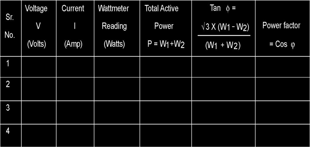
15 following things.) Measurement of reactive power in 3 phase circuit by one wattmeter method. Refer to proposition 4 and draw the circuit diagram. 1 Use 3 phase balanced load. 2 Show switch, fuse and meters. APPARATUS : 3 phase Variac (0-415V) A. C. Ammeter (0-5A) A. C. Voltmeter (0-300V) Wattmeter (300V, 5A, 625Watts) Variable power factor load. STEPWISE PROCEDURE : Part A Make the connections as per the circuit diagram. Check and adjust zero indication of wattmeter and note the multiplying factor of wattmeter. Switch on the supply. Adjust required amount of supply voltage with variac. Adjust balanced load. Note voltmeter, ammeter & wattmeter reading W1 with switch at 'a'. Note wattmeter reading W2 with the switch at 'b'. Take four readings for different current for balanced load. Switch off the supply. Calculate total active power and power factor. Part B Make the connections as per the circuit diagram. Switch on the supply. Adjust the same values of current for balanced loads as in part (a). Note wattmeter, voltmeter & ammeter reading. Switch off the supply. Observations : Part A - Measurement of active power
16
17 EXPERIMENT NO. 6 Aim: Calibration of 1-cp Energy meter (Induction Type). APPARATUS :- S.No. APPARATUS RANGE TYPE QTY REMARKS 1. Auto Transformer 230v/0-230v Continuously variable 1 2. Load 5kw Resistive THEORY: 1-Φ Energy meter Voltmeter Ammeter Wattmeter Stop Watch 750rev/kwh (0-3 00v) (0-5A) 300v, 5A Induction Induction Type Energy meter is widely used for the measurement of energy consumed in domestic as well as in industrial installations. Induction instruments possess lower friction and higher torque/weight ratio. And these instruments cost less and are accurate over a wide range of loads and temperatures. M.I. M.I There are four main parts of the operating mechanism. (i) Driving System. (ii) Moving System. (iii) Braking System. (iv) Registering Mechanism Principle of Operation: The pressure and current coils of shunt and series magnets produce two alternating fluxes, one proportional to voltage and the other proportional to load currents. These two fluxes when cut the disc induce eddy currents in it. The interaction of the fluxes with the eddy currents sets up a torque on the disc causing it to rotate. The speed of the disc would then be proportional to the power being measured.
18 CIRCUIT DIAGRAM: PROCEDURE:- 1. Connect the circuit as shown in figure. 2. By adjusting the autotransformer keep the voltage across the voltmeter in which current should not exceed 2.8A in the ammeter. 3. By using stopwatch measure time for 5 rev of the disc of the energy meter and take the corresponding readings if voltmeter, ammeter and wattmeter. 4. Repeat step-3 until the ammeter reading should not exceed 2.8A 5. Tabulate the above readings and calculate the % error of the energy meter. TABULAR FORM: S.NO V (volts) I (amp) W, (watts) Rev/Sec CALCULATIONS: %error of the energy meter=(wi-wa)/(w*100) Where Wi = indicating Power (watt) Wa=Actual Power (watt) Wa=KR/t Where 'R' is No. of revolutions 1 Unit=1 KWH=750rev =1000*60*60=1200rev 1 rev/sec= 1/1000 x 60 x 60 / 280
19 K=4800W RESULT:- The percentage error of the energy meter is PRECAUTIONS: (v) Energy meter should not be over loaded. (vi)connect the meters with appropriate meters. (vii) Avoid loose connections to prevent sparks and damage to meters.
20 EXPERIMENT NO. 7 OBJECTIVE:. Study of C.R.O. Voltage measurement on C.R.O. Current measurement on C.R.O. Frequency measurement on C.R.O. Phase difference measurement on C.R.O. APPARATUS REQUIRED : Cathode-ray oscilloscope, millimeter, and oscillator. Theory INTRODUCTION: The cathode-ray oscilloscope (CRO) is a common laboratory instrument that provides accurate time and amplitude measurements of voltage signals over a wide range of frequencies. Its reliability, stability, and ease of operation make it suitable as a general purpose laboratory instrument. The heart of the CRO is a cathode-ray tube shown schematically in Fig. 1. The cathode ray is a beam of electrons which are emitted by the heated cathode (negative electrode) and accelerated toward the fluorescent screen. The assembly of the cathode, intensity grid, focus grid, and accelerating anode (positive electrode) is called an electron gun. Its purpose is to generate the electron beam and control its intensity and focus. Between the electron gun and the fluorescent screen are two pair of metal plates - one oriented to provide horizontal deflection of the beam and one pair oriented ot give vertical deflection to the beam. These plates are thus referred to as the horizontal and vertical deflection plates. The combination of these two deflections allows the beam to reach any portion of the fluorescent screen. Wherever the electron beam hits the screen, the phosphor is excited and light is emitted from that point. This coversion of electron energy into light allows us to write with points or lines of light on an otherwise
21 darkened screen. In the most common use of the oscilloscope the signal to be studied is first amplified and then applied to the vertical (deflection) plates to deflect the beam vertically and at the same time a voltage that increases linearly with time is applied to the horizontal (deflection) plates thus causing the beam to be deflected horizontally at a uniform (constant> rate. The signal applied to the verical plates is thus displayed on the screen as a function of time. The horizontal axis serves as a uniform time scale. CRO Operation: A simplified block diagram of a typical oscilloscope is shown in Fig. 3. In general, the instrument is operated in the following manner. The signal to be displayed is amplified by the vertical amplifier and applied to the verical deflection plates of the CRT. A portion of the signal in the vertical amplifier is applied to the sweep trigger as a triggering signal. The sweep trigger then generates a pulse coincident with a selected point in the cycle of the triggering signal. This pulse turns on the sweep generator, initiating the sawtooth wave form. The sawtooth wave is amplified by the horizontal amplifier and applied to the horizontal deflection plates. Usually, additional provisions signal are made for appliying an external triggering signal or utilizing the 60 Hz line for triggering. Also the sweep generator may be bypassed and an external signal applied directly to the horizontal amplifier. CRO Contro; The controls available on most oscilloscopes provide a wide range of operating conditions and thus make the instrument especially versatile. Since many of these controls are common to most oscilloscopes a brief description of them follows. CATHODE-RAY TUBE Power and Scale Illumination: Turns instrument on and controls illumination of the graticule. Focus: Focus the spot or trace on the screen.
22 Intensity: Regulates the brightness of the spot or trace. VERTICAL AMPLIFIER SECTION Position: Controls vertical positioning of oscilloscope display. Sensitivity: Selects the sensitivity of the vertical amplifier in calibrated steps. Variable Sensitivity: Provides a continuous range of sensitivities between the calibrated steps. Normally the sensitivity is calibrated only when the variable knob is in the fully clockwise position. AC-DC-GND: Selects desired coupling (ac or dc) for incoming signal applied to vertical amplifier, or grounds the amplifier input. Selecting dc couples the input directly to the amplifier; selecting ac send the signal through a capacitor before going to the amplifier thus blocking any constant component. CONNECTIONS FOR THE OSCILLOSCOPE Vertical Input: A pair of jacks for connecting the signal under study to the Y (or vertical) amplifier. The lower jack is grounded to the case. Horizontal Input: A pair of jacks for connecting an external signal to the horizontal amplifier. The lower terminal is graounted to the case of the oscilloscope. External Tigger Input: Input connector for external trigger signal. Cal. Out: Provides amplitude calibrated square waves of 25 and 500 millivolts for use in calibrating the gain of the amplifiers. Accuracy of the vertical deflection is + 3%. Sensitivity is variable. Horizontal sweep should be accurate to within 3%. Range of sweep is variable.
23 Operating Instructions: Before plugging the oscilloscope into a wall receptacle, set the controls as follows: (a) Power switch at off (b) Intensity fully counter clockwise (c) Vertical centering in the center of range (d) Horizontal centering in the center of range (e) Vertica l at 0.2 (f) Sweep times 1 Plug line cord into a standard ac wall receptacle (nominally 118 V). Turn power on. Do not advance the Intensity Control.Allow the scope to warm up for approximately two minutes, then turn the Intensity Control until the beam is visible on the screen. PROCEDURE: I. Set the signal generator to a frequency of 1000 cycles per second. Connect the output from the generator to the vertical input of the oscilloscope. Establish a steady trace of this input signal on the scope. Adjust (play with) all of the scope and signal generator controls until you become familiar with the function of each. The purpose for such "playing" is to allow the student to become so familiar with the oscilloscope that it becomes an aid (tool) in making measurements in other experiments and not as a formidable obstacle. Note: If the vertical gain is set too low, it may not be possible to obtain a steady trace. II. Measurements of Voltage: Consider the circuit in Fig. 4(a). The signal generator is used to produce a 1000 hertz sine wave. The AC voltmeter and the leads to the vertical input of the oscilloscope are connected across the generator's output. By adjusting the Horizontal Sweep time/cm and trigger, a steady trace of the sine wave may be displayed on the screen. The trace represents a plot of voltage vs. time, where the vertical deflection of the trace about the line of symmetry CD is proportional to the magnitude of the voltage at any instant of time.
. The AC voltmeter is designed to read the dc \"effective value\" of the voltage. This effective value is also known as the \"Root Mean Square value\" (RMS) value of the voltage.")
24 To determine the size of the voltage signal appearing at the output of terminals of the signal generator, an AC (Alternating Current) voltmeter is connected in parallel across these terminals (Fig. 4a). The AC voltmeter is designed to read the dc "effective value" of the voltage. This effective value is also known as the "Root Mean Square value" (RMS) value of the voltage. The peak or maximum voltage seen on the scope face (Fig. 4b) is Vm volts and is represented by the distance from the symmetry line CD to the maximum deflection. The relationship between the magnitude of the peak voltage displayed on the scope and the effective or RMS voltage (VRMS) read on the AC voltmeter is cosine wave). Thus VRMS = Vm (for a sine or Agreement is expected between the voltage reading of the multimeter and that of the oscilloscope. For a symmetric wave (sine or cosine) the value of Vmmay be taken as 1/2 the peak to peak signal Vpp The variable sensitivity control a signal may be used to adjust the display to fill a concenient range of the scope face. In this position, the trace is no longer calibrated so that you can not just read the size of the signal by counting the number of divisions and multiplying by the scale factor. However, you can figure out what the new calibration is an use it as long as the variable control remains unchanged. Caution: The mathematical prescription given for RMS signals is valid only for sinusoidal signals. The meter will not indicate the correct voltage when used to measure non-sinusoidal signals.
25 III. Frequency Measurements: When the horizontal sweep voltage is applied, voltage measurements can still be taken from the vertical deflection. Moreover, the signal is displayed as a function of time. If the time base (i.e. sweep) is calibrated, such measurements as pulse duration or signal period can be made. Frequenciescan then be determined as reciprocal of the periods. Set the oscillator to 1000 Hz. Display the signal on the CRO and measure the period of the oscillations. Use the horizontal distance between two points such as C to D in Fig. 4b. Set the horizontal gain so that only one complete wave form is displayed. Then reset the horizontal until 5 waves are seen. Keep the time base control in a calibrated position. Measure the distance (and hence time) for 5 complete cycles and calculate the frequency from this measurement. Compare you result with the value determined above. Repeat your measurements for other frequencies of 150 Hz, 5 khz, 50 khz as set on the signal generator. IV. Lissajous Figures: When sine-wave signals of different frequencies are input to the horizontal and vertical amplifiers a stationary pattern is formed on the CRT when the ratio of the two frequencies is an intergral fraction such as 1/2, 2/3, 4/3, 1/5, etc. These stationary patterns are known as Lissajous figures and can be used for comparison measurement of frequencies. Use two oscillators to generate some simple Lissajous figures like those shown in Fig. 5. You will find it difficult to maintain the Lissajous figures in a fixed configuration because the two oscillators are not phase and frequency locked. Their frequencies and phase drift slowly causing the two different signals to change slightly with respect to each other. V. Testing what you have learned: Your instructor will provide you with a small oscillator circuit. Examine the input to the circuit and output of the circuit using your oscilloscope. Measure such quantities as the voltage and frequence of the signals. Specify if they are sinusoidal or of some other wave character. If square wave, measure the frequency of the wave. Also, for square waves, measure the on time (when the voltage is high) and off time (when it is low).
26 Result:- Study is completed Precautions: 1.Operate cro carefully 2.Take all reading carefully 3.Use correct power supply
27 EXPERIMENT NO.8 Experiment Name: To measure frequency by Wien's bridge Apparatus Required: 1. Wien`s Bridge Trainer 2. Multi meter 3. 2mm Patch cords Theory: In this bridge circuit, there is a lead-lag network. Balancing of the bridge is easier because satisfying the phase angle equality condition can be achieved. This bridge can also be used to determine the frequency of the AC input in terms of the component values of the bridge circuit. In this AC bridge, there is no inductor. Inductive losses because of stray fields cause problems in balancing of the bridge. Owing to the absence of L in the circuit, this can be effectively used for determining the frequency f of the AC input..
28 Procedure: 1. Connect mains cord to the Trainer. 2. Connect terminal 1 to 4(for evaluating unknown capacitance Cx1). 3. Rotate variable resistance R1 towards anti clockwise direction. 4. Select Frequency Selector f or any desired range of frequency. 100 Hz to 1 khz 1 khz to 10 khz 10 khz to 60 khz 7. For example 2 khz frequency, select frequency select or between the ranges1 khz-10 khz. 8. Use Frequency Variable knob to set 2 khz frequency on display screen. 9. Connect terminal 19 to 6 and 20 to Now switch On the power supply. 11. Set toggle of null detector towards on condition. 12. Vary Amplitude Variable f or enough sound of speaker. 13. Vary resistance R1 towards clockwise direction slowly. (Sound diminishes). Keep varying R1 until you get very low sound or null sound (null condition). 16. Now remove the patch cord between terminal 1 & 4 and record the value of R1 in the observation table using multimeter. Observation Table: S No. R1 R2 C1 C2 f Calculations:
29 Precaution: 1. Handle all the equipments with care 2. Make connections according to circuit diagram 3. Take the readings carefully& the connections should be tight
Bhoj Reddy Engineering College for Women, Hyderabad Department of Electronics and Communication Engineering Electrical and Electronics Instrumentation
 Bhoj Reddy Engineering College for Women, Hyderabad Department of Electronics and Communication Engineering Electrical and Electronics Instrumentation Academic Year: 2016-17 III B Tech II Semester Branch:
SIR C R REDDY COLLEGE OF ENGINEERING EEE Department, ELURU.
 EEE3110-ELECTRICAL MEASUREMENTS LAB III/IV EEE, I Semester SIR C R REDDY COLLEGE OF ENGINEERING EEE Department, ELURU. NAME:. REGD.NO: SECTION:..Academic Year:.. SIR.C.R.REDDY COLLEGE OF ENGINEERING
Jawaharlal Nehru Engineering College, Aurangabad.
 Jawaharlal Nehru Engineering College, Aurangabad. Laboratory Manual ELECTRICAL MEASUREMENT & TEACHNIQUES [EMT] For Second Year (EEP) Students Manual made by- Prof. J.S.Solanke FORWARD It is my great pleasure
Oscilloscope Measurements
 PC1143 Physics III Oscilloscope Measurements 1 Purpose Investigate the fundamental principles and practical operation of the oscilloscope using signals from a signal generator. Measure sine and other waveform
VALLIAMMAI ENGINEERING COLLEGE
 VALLIAMMAI ENGINEERING COLLEGE SRM NAGAR, KATTANKULATHUR 603203 DEPARTMENT OF ELECTRICAL AND ELECTRONICS ENGINEERING EE8261-ELECTRIC CIRCUITS LABORATORY LABORATORY MANUAL 1 ST YEAR EEE (REGULATION 2017)
TITLE: Introduction to various Basic Instruments of Electrical Science
 EXPERIMENT NO : 1 TITLE: Introduction to various Basic Instruments of Electrical Science OBJECTIVE: Introduction to various Supply Systems, Ammeter, Voltmeter, Wattmeter, Energy meter, Tachometer, Rheostat,
Table of Contents...2. About the Tutorial...6. Audience...6. Prerequisites...6. Copyright & Disclaimer EMI INTRODUCTION Voltmeter...
 1 Table of Contents Table of Contents...2 About the Tutorial...6 Audience...6 Prerequisites...6 Copyright & Disclaimer...6 1. EMI INTRODUCTION... 7 Voltmeter...7 Ammeter...8 Ohmmeter...8 Multimeter...9
SRI SUKHMANI INSTITUTE OF ENGINEERING & TECHNOLOGY DERA BASSI DEPARTMENT: ELECTRONICS & COMM. LABORATORY MANUAL LAB: EMI SUBJECT CODE: SEMESTER: 4th
 SRI SUKHMANI INSTITUTE OF ENGINEERING & TECHNOLOGY DERA BASSI DEPARTMENT: ELECTRONICS & COMM. LABORATORY MANUAL LAB: EMI SUBJECT CODE: SEMESTER: 4th EXPERIMENT NO-1 Aim:- Low Resistance Using Kelvin Double
SIDDHARTH GROUP OF INSTITUTIONS :: PUTTUR (AUTONOMOUS) Siddharth Nagar, Narayanavanam Road QUESTION BANK (DESCRIPTIVE)
 Siddharth Nagar, Narayanavanam Road QUESTION BANK (DESCRIPTIVE)") SIDDHARTH GROUP OF INSTITUTIONS :: PUTTUR (AUTONOMOUS) Siddharth Nagar, Narayanavanam Road 517583 QUESTION BANK (DESCRIPTIVE) Suject : Electrical & Electronic Measurements(16EE224) Year & Sem: III-B.Tech
SIDDHARTH GROUP OF INSTITUTIONS :: PUTTUR (AUTONOMOUS) Siddharth Nagar, Narayanavanam Road 517583 QUESTION BANK (DESCRIPTIVE) Suject : Electrical & Electronic Measurements(16EE224) Year & Sem: III-B.Tech
Laboratory Exercise 6 THE OSCILLOSCOPE
 Introduction Laboratory Exercise 6 THE OSCILLOSCOPE The aim of this exercise is to introduce you to the oscilloscope (often just called a scope), the most versatile and ubiquitous laboratory measuring
electrical noise and interference, environmental changes, instrument resolution, or uncertainties in the measurement process itself.
 MUST 382 / EELE 491 Spring 2014 Basic Lab Equipment and Measurements Electrical laboratory work depends upon various devices to supply power to a circuit, to generate controlled input signals, and for
INSTITUTE OF AERONAUTICAL ENGINEERING (Autonomous) Dundigal, Hyderabad ELECTRICAL AND ELECTRONICS ENGINEERING
 Dundigal, Hyderabad ELECTRICAL AND ELECTRONICS ENGINEERING") INSTITUTE OF AERONAUTICAL ENGINEERING (Autonomous) Dundigal, Hyderabad - 500 043 ELECTRICAL AND ELECTRONICS ENGINEERING QUESTION BANK Course Name : Electrical and Electronics Instrumentation Course Code
INSTITUTE OF AERONAUTICAL ENGINEERING (Autonomous) Dundigal, Hyderabad - 500 043 ELECTRICAL AND ELECTRONICS ENGINEERING QUESTION BANK Course Name : Electrical and Electronics Instrumentation Course Code
Department of Electrical and Computer Engineering. Laboratory Experiment 1. Function Generator and Oscilloscope
 Department of Electrical and Computer Engineering Laboratory Experiment 1 Function Generator and Oscilloscope The purpose of this first laboratory assignment is to acquaint you with the function generator
Goals. Introduction. To understand the use of root mean square (rms) voltages and currents.
 voltages and currents.") Lab 10. AC Circuits Goals To show that AC voltages cannot generally be added without accounting for their phase relationships. That is, one must account for how they vary in time with respect to one another.
Lab 10. AC Circuits Goals To show that AC voltages cannot generally be added without accounting for their phase relationships. That is, one must account for how they vary in time with respect to one another.
Lab 1: Basic Lab Equipment and Measurements
 Abstract: Lab 1: Basic Lab Equipment and Measurements This lab exercise introduces the basic measurement instruments that will be used throughout the course. These instruments include multimeters, oscilloscopes,
Name Date: Course number: MAKE SURE TA & TI STAMPS EVERY PAGE BEFORE YOU START EXPERIMENT 10. Electronic Circuits
 Laboratory Section: Last Revised on September 21, 2016 Partners Names: Grade: EXPERIMENT 10 Electronic Circuits 1. Pre-Laboratory Work [2 pts] 1. How are you going to determine the capacitance of the unknown
Electronic Measurements & Instrumentation. 1. Draw the Maxwell s Bridge Circuit and derives the expression for the unknown element at balance?
 UNIT -6 1. Draw the Maxwell s Bridge Circuit and derives the expression for the unknown element at balance? Ans: Maxwell's bridge, shown in Fig. 1.1, measures an unknown inductance in of standard arm offers
EE ELECTRICAL ENGINEERING AND INSTRUMENTATION
 EE6352 - ELECTRICAL ENGINEERING AND INSTRUMENTATION UNIT V ANALOG AND DIGITAL INSTRUMENTS Digital Voltmeter (DVM) It is a device used for measuring the magnitude of DC voltages. AC voltages can be measured
General Construction & Operation of Oscilloscopes
 Science 14 Lab 2: The Oscilloscope Introduction General Construction & Operation of Oscilloscopes An oscilloscope is a widely used device which uses a beam of high speed electrons (on the order of 10 7
MAHARASHTRA STATE BOARD OF TECHNICAL EDUCATION (Autonomous) (ISO/IEC Certified) SUMMER 14 EXAMINATION Model Answer
 (ISO/IEC Certified) SUMMER 14 EXAMINATION Model Answer") MAHARASHTRA STATE BOARD OF TECHNICAL EDUCATION (Autonomous) (ISO/IEC 27001 2005 Certified) SUMMER 14 EXAMINATION Model Answer Subject Code : 17317 Page No: 1 Important Instructions to examiners: 1) The
MAHARASHTRA STATE BOARD OF TECHNICAL EDUCATION (Autonomous) (ISO/IEC 27001 2005 Certified) SUMMER 14 EXAMINATION Model Answer Subject Code : 17317 Page No: 1 Important Instructions to examiners: 1) The
University of TN Chattanooga Physics1040L 8/29/2012 PHYSICS 1040L LAB LAB 6: USE OF THE OSCILLOSCOPE
 PHYSICS 1040L LAB LAB 6: USE OF THE OSCILLOSCOPE Object: To become familiar with the operation of the oscilloscope and be able to use an oscilloscope for: 1. Measuring the frequency of an oscillator, 2.
Exp. #2-6 : Measurement of the Characteristics of,, and Circuits by Using an Oscilloscope
 PAGE 1/14 Exp. #2-6 : Measurement of the Characteristics of,, and Circuits by Using an Oscilloscope Student ID Major Name Team No. Experiment Lecturer Student's Mentioned Items Experiment Class Date Submission
ECE 53A: Fundamentals of Electrical Engineering I
 ECE 53A: Fundamentals of Electrical Engineering I Laboratory Assignment #1: Instrument Operation, Basic Resistor Measurements and Kirchhoff s Laws Fall 2007 General Guidelines: - Record data and observations
ME 365 EXPERIMENT 1 FAMILIARIZATION WITH COMMONLY USED INSTRUMENTATION
 Objectives: ME 365 EXPERIMENT 1 FAMILIARIZATION WITH COMMONLY USED INSTRUMENTATION The primary goal of this laboratory is to study the operation and limitations of several commonly used pieces of instrumentation:
RADIO AMATEUR EXAM GENERAL CLASS
 RAE-Lessons by 4S7VJ 1 CHAPTER-7 RADIO AMATEUR EXAM GENERAL CLASS MEASURMENTS By 4S7VJ 7.1 TEST EQUIPMENT & MEASUREMENTS Correct operation of amateur radio equipment involves measurements to ensure optimum
Code No: RR Set No. 1
 Code No: RR310202 Set No. 1 III B.Tech I Semester Regular Examinations, November 2006 ELECTRICAL MEASUREMENTS (Electrical & Electronic Engineering) Time: 3 hours Max Marks: 80 Answer any FIVE Questions
Sirindhorn International Institute of Technology Thammasat University at Rangsit
 Sirindhorn International Institute of Technology Thammasat University at Rangsit School of Information, Computer and Communication Technology COURSE : ECS 210 Basic Electrical Engineering Lab INSTRUCTOR
ELECTRIC CIRCUITS CMPE 253 DEPARTMENT OF COMPUTER ENGINEERING LABORATORY MANUAL ISHIK UNIVERSITY
 ELECTRIC CIRCUITS CMPE 253 DEPARTMENT OF COMPUTER ENGINEERING LABORATORY MANUAL ISHIK UNIVERSITY 2017-2018 1 WEEK EXPERIMENT TITLE NUMBER OF EXPERIMENT No Meeting Instructional Objective 2 Tutorial 1 3
Note: 1. All the students must strictly follow all the safety precautions. 2. In case of any question or concern, please contact LAB INSTRUCTOR or TA.
 UNIVERSITY OF WATERLOO ELECTRICAL & COMPUTER ENGINEERING DEPARTMENT FALL 2006 E&CE 261: Energy Systems and Components EXPERIMENT 1: THREE-PHASE SYSTEMS Contents covered in this laboratory exercise: 1.
Measurement of Resistance and Potentiometers
 Electrical Measurements International Program Department of Electrical Engineering UNIVERSITAS INDONESIA Measurement of Resistance and Potentiometers Jahroo Renardi Lecturer : Ir. Chairul Hudaya, ST, M.Eng.,
Laboratory 3 (drawn from lab text by Alciatore)
") Laboratory 3 (drawn from lab text by Alciatore) The Oscilloscope Required Components: 1 10 resistor 2 100 resistors 2 lk resistors 1 2k resistor 2 4.7M resistors 1 0.F capacitor 1 0.1 F capacitor 1 1.0uF
Laboratory 3 (drawn from lab text by Alciatore) The Oscilloscope Required Components: 1 10 resistor 2 100 resistors 2 lk resistors 1 2k resistor 2 4.7M resistors 1 0.F capacitor 1 0.1 F capacitor 1 1.0uF
(Approved by AICTE & Affiliated to Calicut University) DEPARTMENT OF ELECTRICAL & ELECTRONICS ENGINEERING : ELECTRICAL MEASUREMENTS AND
 DEPARTMENT OF ELECTRICAL & ELECTRONICS ENGINEERING : ELECTRICAL MEASUREMENTS AND") (Approved by AICTE & Affiliated to Calicut University) DEPARTMENT OF ELECTRICAL & ELECTRONICS ENGINEERING ELECTRICAL MEASUREMENTS AND INSTRUMENTATION LAB CLASS SEMESTER SUBJECT CODE SUBJECT : II YEAR (EEE)
(Approved by AICTE & Affiliated to Calicut University) DEPARTMENT OF ELECTRICAL & ELECTRONICS ENGINEERING ELECTRICAL MEASUREMENTS AND INSTRUMENTATION LAB CLASS SEMESTER SUBJECT CODE SUBJECT : II YEAR (EEE)
Introduction to Electronic Equipment
 Introduction to Electronic Equipment INTRODUCTION This semester you will be exploring electricity and magnetism. In order to make your time in here more instructive we ve designed this laboratory exercise
THE CATHODE RAY OSCILLOSCOPE
 The Department of Engineering SS1.2 THE CATHODE RAY OSCILLOSCOPE Objectives The objective of this laboratory is for you to familiarise yourself with the operation of a cathode ray oscilloscope (CRO). Once
DEPARTMENT OF ELECTRICAL AND ELECTRONICS ENGINEERING EE6211-ELECTRIC CIRCUITS LABORATORY LABORATORY MANUAL 1ST YEAR EEE (REGULATION 2013)
") DEPARTMENT OF ELECTRICAL AND ELECTRONICS ENGINEERING EE62-ELECTRIC CIRCUITS LABORATORY LABORATORY MANUAL ST YEAR EEE (REGULATION 203) EE62 ELECTRIC CIRCUITS LABORATORY LTPC0032 LIST OF EXPERIMENTS. Experimental
DEPARTMENT OF ELECTRICAL AND ELECTRONICS ENGINEERING EE62-ELECTRIC CIRCUITS LABORATORY LABORATORY MANUAL ST YEAR EEE (REGULATION 203) EE62 ELECTRIC CIRCUITS LABORATORY LTPC0032 LIST OF EXPERIMENTS. Experimental
Brown University PHYS 0060 Physics Department LAB B Circuits with Resistors and Diodes
 References: Circuits with Resistors and Diodes Edward M. Purcell, Electricity and Magnetism 2 nd ed, Ch. 4, (McGraw Hill, 1985) R.P. Feynman, Lectures on Physics, Vol. 2, Ch. 22, (Addison Wesley, 1963).
Episode 123: Alternating current
 Episode 123: Alternating current The aims are to distinguish alternating from direct currents and to remind your students of why ac is so important (they should already have met this at pre-16 level).
ELECTRICAL MEASUREMENTS
 R10 Set No: 1 1. a) Derive the expression for torque equation for a moving iron attraction type instrument and comment up on the nature of scale [8] b) Define the terms current sensitivity, voltage sensitivity
ELECTRICAL ENGINEERING LABORATORY MANUAL (NEE 151/251)
") ELECTRICAL ENGINEERING LABORATORY MANUAL (NEE 151/251) DEPARTMENTS OF ELECTRONICS & COMMUNICATION ENGINEERING/ ELECTRICAL ENGINEERING 27, Knowledge Park-III, Greater Noida, (U.P.) Phone: 0120-2323854-58
ELECTRICAL ENGINEERING LABORATORY MANUAL (NEE 151/251) DEPARTMENTS OF ELECTRONICS & COMMUNICATION ENGINEERING/ ELECTRICAL ENGINEERING 27, Knowledge Park-III, Greater Noida, (U.P.) Phone: 0120-2323854-58
University of Jordan School of Engineering Electrical Engineering Department. EE 204 Electrical Engineering Lab
 University of Jordan School of Engineering Electrical Engineering Department EE 204 Electrical Engineering Lab EXPERIMENT 1 MEASUREMENT DEVICES Prepared by: Prof. Mohammed Hawa EXPERIMENT 1 MEASUREMENT
15. the power factor of an a.c circuit is.5 what will be the phase difference between voltage and current in this
 1 1. In a series LCR circuit the voltage across inductor, a capacitor and a resistor are 30 V, 30 V and 60 V respectively. What is the phase difference between applied voltage and current in the circuit?
POLYTECHNIC UNIVERSITY Electrical Engineering Department. EE SOPHOMORE LABORATORY Experiment 3 The Oscilloscope
 POLYTECHNIC UNIVERSITY Electrical Engineering Department EE SOPHOMORE LABORATORY Experiment 3 The Oscilloscope Modified for Physics 18, Brooklyn College I. Overview of the Experiment The main objective
University of Jordan School of Engineering Electrical Engineering Department. EE 219 Electrical Circuits Lab
 University of Jordan School of Engineering Electrical Engineering Department EE 219 Electrical Circuits Lab EXPERIMENT 7 RESONANCE Prepared by: Dr. Mohammed Hawa EXPERIMENT 7 RESONANCE OBJECTIVE This experiment
Ahsanullah University of Science and Technology
 Ahsanullah University of Science and Technology Department of Electrical and Electronic Engineering AU ST /E EE LABORATORY MANUAL FOR ELECTRICAL AND ELECTRONIC SESSIONAL COURSE Student Name : Student ID
Experiment 5 The Oscilloscope
 Experiment 5 The Oscilloscope Vision is the art of seeing things invisible. J. Swift (1667-1745) OBJECTIVE To learn to operate a cathode ray oscilloscope. THEORY The oscilloscope, or scope for short, is
ELECTRICAL CIRCUITS LABORATORY MANUAL (II SEMESTER)
") ELECTRICAL CIRCUITS LABORATORY MANUAL (II SEMESTER) LIST OF EXPERIMENTS. Verification of Ohm s laws and Kirchhoff s laws. 2. Verification of Thevenin s and Norton s Theorem. 3. Verification of Superposition
ELECTRICAL CIRCUITS LABORATORY MANUAL (II SEMESTER) LIST OF EXPERIMENTS. Verification of Ohm s laws and Kirchhoff s laws. 2. Verification of Thevenin s and Norton s Theorem. 3. Verification of Superposition
Experiment 9 AC Circuits
 Experiment 9 AC Circuits "Look for knowledge not in books but in things themselves." W. Gilbert (1540-1603) OBJECTIVES To study some circuit elements and a simple AC circuit. THEORY All useful circuits
ECE 2006 University of Minnesota Duluth Lab 11. AC Circuits
 1. Objective AC Circuits In this lab, the student will study sinusoidal voltages and currents in order to understand frequency, period, effective value, instantaneous power and average power. Also, the
UNIVERSITY OF TECHNOLOGY, JAMAICA SCHOOL OF ENGENEERING. Electrical Engineering Science. Laboratory Manual
 UNIVERSITY OF TECHNOLOGY, JAMAICA SCHOOL OF ENGENEERING Electrical Engineering Science Laboratory Manual Table of Contents Experiment #1 OHM S LAW... 3 Experiment # 2 SERIES AND PARALLEL CIRCUITS... 8
Dhanalakshmi Srinivasan Institute of Technology, Samayapuram, Trichy. Cycle 2 EE6512 Electrical Machines II Lab Manual
 Cycle 2 EE652 Electrical Machines II Lab Manual CIRCUIT DIAGRAM FOR SLIP TEST 80V DC SUPPLY 350Ω, 2 A 3 Point Starter L F A NAME PLATE DETAILS: 3Ф alternator DC shunt motor FUSE RATING: Volts: Volts: 25%
ECE 480: SENIOR DESIGN LABORATORY
 ECE 480: SENIOR DESIGN LABORATORY DEPARTMENT OF ELECTRICAL AND COMPUTER ENGINEERING MICHIGAN STATE UNIVERSITY I. TITLE: Lab I - Introduction to the Oscilloscope, Function Generator, Digital Multimeter
The University of Jordan Mechatronics Engineering Department Electronics Lab.( ) Experiment 1: Lab Equipment Familiarization
 Experiment 1: Lab Equipment Familiarization") The University of Jordan Mechatronics Engineering Department Electronics Lab.(0908322) Experiment 1: Lab Equipment Familiarization Objectives To be familiar with the main blocks of the oscilloscope and
The University of Jordan Mechatronics Engineering Department Electronics Lab.(0908322) Experiment 1: Lab Equipment Familiarization Objectives To be familiar with the main blocks of the oscilloscope and
CHAPTER 6. Motor Driver
 CHAPTER 6 Motor Driver In this lab, we will construct the circuitry that your robot uses to drive its motors. However, before testing the motor circuit we will begin by making sure that you are able to
RAO PAHALD SINGH GROUP OF INSTITUTIONS BALANA(MOHINDER GARH)123029
123029") 1 Analog Electronics Lab (EE-222-F) Analog Electronics Lab (EE-222-F) LAB MANUAL IV SEMESTER RAO PAHALD SINGH GROUP OF INSTITUTIONS BALANA(MOHINDER GARH)123029 Department Of Electronics and Communication
1 Analog Electronics Lab (EE-222-F) Analog Electronics Lab (EE-222-F) LAB MANUAL IV SEMESTER RAO PAHALD SINGH GROUP OF INSTITUTIONS BALANA(MOHINDER GARH)123029 Department Of Electronics and Communication
EE 210: CIRCUITS AND DEVICES
 EE 210: CIRCUITS AND DEVICES LAB #3: VOLTAGE AND CURRENT MEASUREMENTS This lab features a tutorial on the instrumentation that you will be using throughout the semester. More specifically, you will see
Ph 3455 The Franck-Hertz Experiment
 Ph 3455 The Franck-Hertz Experiment Required background reading Tipler, Llewellyn, section 4-5 Prelab Questions 1. In this experiment, we will be using neon rather than mercury as described in the textbook.
ET1210: Module 5 Inductance and Resonance
 Part 1 Inductors Theory: When current flows through a coil of wire, a magnetic field is created around the wire. This electromagnetic field accompanies any moving electric charge and is proportional to
ECE 201 LAB 8 TRANSFORMERS & SINUSOIDAL STEADY STATE ANALYSIS
 Version 1.1 1 of 8 ECE 201 LAB 8 TRANSFORMERS & SINUSOIDAL STEADY STATE ANALYSIS BEFORE YOU BEGIN PREREQUISITE LABS Introduction to MATLAB Introduction to Lab Equipment Introduction to Oscilloscope Capacitors,
Electrical Machines (EE-343) For TE (ELECTRICAL)
 For TE (ELECTRICAL)") PRACTICALWORKBOOK Electrical Machines (EE-343) For TE (ELECTRICAL) Name: Roll Number: Year: Batch: Section: Semester: Department: N.E.D University of Engineering &Technology, Karachi Electrical Machines
PRACTICALWORKBOOK Electrical Machines (EE-343) For TE (ELECTRICAL) Name: Roll Number: Year: Batch: Section: Semester: Department: N.E.D University of Engineering &Technology, Karachi Electrical Machines
1. (a) Determine the value of Resistance R and current in each branch when the total current taken by the curcuit in figure 1a is 6 Amps.
 Determine the value of Resistance R and current in each branch when the total current taken by the curcuit in figure 1a is 6 Amps.") Code No: 07A3EC01 Set No. 1 II B.Tech I Semester Regular Examinations, November 2008 ELECTRICAL AND ELECTRONICS ENGINEERING ( Common to Civil Engineering, Mechanical Engineering, Mechatronics, Production
Code No: 07A3EC01 Set No. 1 II B.Tech I Semester Regular Examinations, November 2008 ELECTRICAL AND ELECTRONICS ENGINEERING ( Common to Civil Engineering, Mechanical Engineering, Mechatronics, Production
Exercise 9: inductor-resistor-capacitor (LRC) circuits
 circuits") Exercise 9: inductor-resistor-capacitor (LRC) circuits Purpose: to study the relationship of the phase and resonance on capacitor and inductor reactance in a circuit driven by an AC signal. Introduction
Exercise 9: inductor-resistor-capacitor (LRC) circuits Purpose: to study the relationship of the phase and resonance on capacitor and inductor reactance in a circuit driven by an AC signal. Introduction
UNIT II MEASUREMENT OF POWER & ENERGY
 UNIT II MEASUREMENT OF POWER & ENERGY Dynamometer type wattmeter works on a very simple principle which is stated as "when any current carrying conductor is placed inside a magnetic field, it experiences
UNIT 2. Q.1) Describe the functioning of standard signal generator. Ans. Electronic Measurements & Instrumentation
 Describe the functioning of standard signal generator. Ans. Electronic Measurements & Instrumentation") UNIT 2 Q.1) Describe the functioning of standard signal generator Ans. STANDARD SIGNAL GENERATOR A standard signal generator produces known and controllable voltages. It is used as power source for the
UNIT 2 Q.1) Describe the functioning of standard signal generator Ans. STANDARD SIGNAL GENERATOR A standard signal generator produces known and controllable voltages. It is used as power source for the
1. Explain in detail the constructional details and working of DC motor.
 DHANALAKSHMI SRINIVASAN INSTITUTE OF RESEARCH AND TECHNOLOGY, PERAMBALUR DEPT OF ECE EC6352-ELECTRICAL ENGINEERING AND INSTRUMENTATION UNIT 1 PART B 1. Explain in detail the constructional details and
AC CURRENTS, VOLTAGES, FILTERS, and RESONANCE
 July 22, 2008 AC Currents, Voltages, Filters, Resonance 1 Name Date Partners AC CURRENTS, VOLTAGES, FILTERS, and RESONANCE V(volts) t(s) OBJECTIVES To understand the meanings of amplitude, frequency, phase,
Maltase cross tube. D. Senthilkumar P a g e 1
 Thermionic Emission Maltase cross tube Definition: The emission of electrons when a metal is heated to a high temperature Explanation: In metals, there exist free electrons which are able to move around
FYSP1110/K1 (FYSP110/K1) USE OF AN OSCILLOSCOPE
 USE OF AN OSCILLOSCOPE") FYSP1110/K1 (FYSP110/K1) USE OF AN OSCILLOSCOPE 1 Introduction In this exercise you will get basic knowledge about how to use an oscilloscope. You ll also measure properties of components, which you are
FYSP1110/K1 (FYSP110/K1) USE OF AN OSCILLOSCOPE 1 Introduction In this exercise you will get basic knowledge about how to use an oscilloscope. You ll also measure properties of components, which you are
APPENDIX D DISCUSSION OF ELECTRONIC INSTRUMENTS
 APPENDIX D DISCUSSION OF ELECTRONIC INSTRUMENTS DC POWER SUPPLIES We will discuss these instruments one at a time, starting with the DC power supply. The simplest DC power supplies are batteries which
EECE208 INTRO To ELECTRICAL ENG LAB. LAB 2. Instrumentation
 EECE208 INTRO To ELECTRICAL ENG LAB Dr. Charles Kim LAB 2. Instrumentation Objectives A brief description of the equipment (Oscilloscope, Function Generator, Power Supply, and Digital Multimeter) and its
Kuestion Electrical and Electronic Measurements
 Kuestion Electrical and Electronic Measurements www.kreatryx.com Contents Manual for Kuestion... 2 Type : Error Analysis... 3 Type 2: Enhancement of Instrument Range... 5 Type 3:PMMC... 6 Type 4: Moving
2.0 AC CIRCUITS 2.1 AC VOLTAGE AND CURRENT CALCULATIONS. ECE 4501 Power Systems Laboratory Manual Rev OBJECTIVE
 2.0 AC CIRCUITS 2.1 AC VOLTAGE AND CURRENT CALCULATIONS 2.1.1 OBJECTIVE To study sinusoidal voltages and currents in order to understand frequency, period, effective value, instantaneous power and average
AME140 Lab #2 INTRODUCTION TO ELECTRONIC TEST EQUIPMENT AND BASIC ELECTRONICS MEASUREMENTS
 INTRODUCTION TO ELECTRONIC TEST EQUIPMENT AND BASIC ELECTRONICS MEASUREMENTS The purpose of this document is to guide students through a few simple activities to increase familiarity with basic electronics
EE 201 Function / Arbitrary Waveform Generator and Oscilloscope Tutorial
 EE 201 Function / Arbitrary Waveform Generator and Oscilloscope Tutorial 1 This is a programmed learning instruction manual. It is written for the Agilent DSO3202A Digital Storage Oscilloscope. The prerequisite
Dev Bhoomi Institute Of Technology Department of Electronics and Communication Engineering PRACTICAL INSTRUCTION SHEET
 Dev Bhoomi Institute Of Technology Department of Electronics and Communication Engineering PRACTICAL INSTRUCTION SHEET LABORATORY MANUAL EXPERIMENT NO. ISSUE NO. : ISSUE DATE: REV. NO. : REV. DATE : PAGE:
Performance-based assessments for AC circuit competencies
 Performance-based assessments for AC circuit competencies This worksheet and all related files are licensed under the Creative Commons Attribution License, version 1.0. To view a copy of this license,
AP Physics C. Alternating Current. Chapter Problems. Sources of Alternating EMF
 AP Physics C Alternating Current Chapter Problems Sources of Alternating EMF 1. A 10 cm diameter loop of wire is oriented perpendicular to a 2.5 T magnetic field. What is the magnetic flux through the
DC and AC Circuits. Objective. Theory. 1. Direct Current (DC) R-C Circuit
 R-C Circuit") [International Campus Lab] Objective Determine the behavior of resistors, capacitors, and inductors in DC and AC circuits. Theory ----------------------------- Reference -------------------------- Young
[International Campus Lab] Objective Determine the behavior of resistors, capacitors, and inductors in DC and AC circuits. Theory ----------------------------- Reference -------------------------- Young
PHY203: General Physics III Lab page 1 of 5 PCC-Cascade. Lab: AC Circuits
 PHY203: General Physics III Lab page 1 of 5 Lab: AC Circuits OBJECTIVES: EQUIPMENT: Universal Breadboard (Archer 276-169) 2 Simpson Digital Multimeters (464) Function Generator (Global Specialties 2001)*
Using Circuits, Signals and Instruments
 Using Circuits, Signals and Instruments To be ignorant of one s ignorance is the malady of the ignorant. A. B. Alcott (1799-1888) Some knowledge of electrical and electronic technology is essential for
University of Pennsylvania Department of Electrical and Systems Engineering. ESE 206: Electrical Circuits and Systems II - Lab
 University of Pennsylvania Department of Electrical and Systems Engineering ESE 206: Electrical Circuits and Systems II - Lab AC POWER ANALYSIS AND DESIGN I. Purpose and Equipment: Provide experimental
Lab 8 - INTRODUCTION TO AC CURRENTS AND VOLTAGES
 08-1 Name Date Partners ab 8 - INTRODUCTION TO AC CURRENTS AND VOTAGES OBJECTIVES To understand the meanings of amplitude, frequency, phase, reactance, and impedance in AC circuits. To observe the behavior
SHRI ANGALAMMAN COLLEGE OF ENGINEERING & TECHNOLOGY (An ISO 9001:2008 Certified Institution) SIRUGANOOR,TRICHY
 SIRUGANOOR,TRICHY") SHRI ANGALAMMAN COLLEGE OF ENGINEERING & TECHNOLOGY (An ISO 9001:2008 Certified Institution) SIRUGANOOR,TRICHY-621105. DEPARTMENT OF ELECTRICAL AND ELECTRONICS ENGINEERING EI 1306-MEASUREMENT AND INSTRUMENTATION
SHRI ANGALAMMAN COLLEGE OF ENGINEERING & TECHNOLOGY (An ISO 9001:2008 Certified Institution) SIRUGANOOR,TRICHY-621105. DEPARTMENT OF ELECTRICAL AND ELECTRONICS ENGINEERING EI 1306-MEASUREMENT AND INSTRUMENTATION
EXAMPLE. Use this jack for the red test lead when measuring. current from 0 to 200mA. Figure P-1
 Digital Multimeters ON / OFF power switch Continuity / Diode Test Function Resistance Function Ranges from 200Ω to 200MΩ Transistor Test Function DC Current Function Ranges from 2mA to 20A. AC Current
Experiment 45. Three-Phase Circuits. G 1. a. Using your Power Supply and AC Voltmeter connect the circuit shown OBJECTIVE
 Experiment 45 Three-Phase Circuits OBJECTIVE To study the relationship between voltage and current in three-phase circuits. To learn how to make delta and wye connections. To calculate the power in three-phase
Test No. 1. Introduction to Scope Measurements. Report History. University of Applied Sciences Hamburg. Last chance!! EEL2 No 1
 University of Applied Sciences Hamburg Group No : DEPARTMENT OF INFORMATION ENGINEERING Laboratory for Instrumentation and Measurement L: in charge of the report Test No. Date: Assistant A2: Professor:
LAB 7: THE OSCILLOSCOPE
 LAB 7: THE OSCILLOSCOPE Equipment List: Dual Trace Oscilloscope HP function generator HP-DMM 2 BNC-to-BNC 1 cables (one long, one short) 1 BNC-to-banana 1 BNC-probe Hand-held DMM (freq mode) Purpose: To
Module 1. Introduction. Version 2 EE IIT, Kharagpur
 Module 1 Introduction Lesson 1 Introducing the Course on Basic Electrical Contents 1 Introducing the course (Lesson-1) 4 Introduction... 4 Module-1 Introduction... 4 Module-2 D.C. circuits.. 4 Module-3
TEST EQUIPMENT AND MEASUREMENTS
 Reading 39 Ron Bertrand VK2DQ http://www.radioelectronicschool.com SSB MEASUREMENTS Why use a two-tone test signal? TEST EQUIPMENT AND MEASUREMENTS The two-tone test signal is the standard modulating signal
Electrical Measurements
 Electrical Measurements INTRODUCTION In this section, electrical measurements will be discussed. This will be done by using simple experiments that introduce a DC power supply, a multimeter, and a simplified
Synchronous Machines Study Material
 Synchronous machines: The machines generating alternating emf from the mechanical input are called alternators or synchronous generators. They are also known as AC generators. All modern power stations
Cornerstone Electronics Technology and Robotics Week 21 Electricity & Electronics Section 10.5, Oscilloscope
 Cornerstone Electronics Technology and Robotics Week 21 Electricity & Electronics Section 10.5, Oscilloscope Field trip to Deerhaven Generation Plant: Administration: o Prayer o Turn in quiz Electricity
10 Electromagnetic Interactions
 Lab 10 Electromagnetic Interactions What You Need To Know: The Physics Electricity and magnetism are intrinsically linked and not separate phenomena. A changing magnetic field can create an electric field
Basic Electronics Prof. T.S. Natarajan Department of Physics Indian Institute of Technology, Madras
 Basic Electronics Prof. T.S. Natarajan Department of Physics Indian Institute of Technology, Madras Lecture 39 Silicon Controlled Rectifier (SCR) (Construction, characteristics (Dc & Ac), Applications,
EECE208 INTRO To ELECTRICAL ENG LAB. LAB 2. Instrumentation
 EECE208 INTRO To ELECTRICAL ENG LAB Dr. Charles Kim LAB 2. Instrumentation Objectives A brief description of the equipment (Oscilloscope, Function Generator, Power Supply, and Digital Multimeter) and its
332:223 Principles of Electrical Engineering I Laboratory Experiment #2 Title: Function Generators and Oscilloscopes Suggested Equipment:
 RUTGERS UNIVERSITY The State University of New Jersey School of Engineering Department Of Electrical and Computer Engineering 332:223 Principles of Electrical Engineering I Laboratory Experiment #2 Title:
UNIVERSITY OF TECHNOLOGY, JAMAICA School of Engineering -
 UNIVERSITY OF TECHNOLOGY, JAMAICA School of Engineering - Electrical Engineering Science Laboratory Manual Table of Contents Safety Rules and Operating Procedures... 3 Troubleshooting Hints... 4 Experiment
2 : AC signals, the signal generator and the Oscilloscope
 2 : AC signals, the signal generator and the Oscilloscope Expected outcomes After conducting this practical, the student should be able to do the following Set up a signal generator to provide a specific
Safety Hazards Instrumentation Laboratory Room 214
 Safety Hazards Instrumentation Laboratory Room 214 HAZARD: Rotating Equipment / Machine Tools Personal Protective Equipment: Safety Goggles; Standing Shields, Sturdy Shoes No: Loose clothing; Neck Ties/Scarves;
ELECTROMAGNETIC INDUCTION AND ALTERNATING CURRENT (Assignment)
") ELECTROMAGNETIC INDUCTION AND ALTERNATING CURRENT (Assignment) 1. In an A.C. circuit A ; the current leads the voltage by 30 0 and in circuit B, the current lags behind the voltage by 30 0. What is the
ELECTROMAGNETIC INDUCTION AND ALTERNATING CURRENT (Assignment) 1. In an A.C. circuit A ; the current leads the voltage by 30 0 and in circuit B, the current lags behind the voltage by 30 0. What is the