Department of Electrical and Computer Engineering. Laboratory Experiment 1. Function Generator and Oscilloscope
|
|
|
- Mavis Hamilton
- 6 years ago
- Views:
Transcription
1 Department of Electrical and Computer Engineering Laboratory Experiment 1 Function Generator and Oscilloscope The purpose of this first laboratory assignment is to acquaint you with the function generator and oscilloscope. The function generator produces a number of periodic waveforms, square, triangular and sine waves. In all cases, both the repetition frequency and amplitude can be varied. The oscilloscope allows you to examine these waveforms. 1.0 Familiarize yourself with the oscilloscope controls by applying a sinusoid to the channel 1 (x) input connector of the ELENCO oscilloscope. Choose a frequency of 120 Hz with a magnitude of 2.0 volts peak to peak at the output of the FG601 Function Generator. Set the vertical volts/div switch on the oscilloscope to.5 so that each division equals.5 volts and four divisions equals 2.0 volts. Set the time base amplifier to auto trigger and sync source channel 1 (x). Adjust the time/div control so that you observe a stationary waveform. Move the lever marked coupling to the normal mode and obtain a stationary waveform by adjusting the level control. Explain why the waveform varies as it does when you adjust the level control. Pull the trig level knob out (- slope) and observe the change. Observe the other waveforms which the FG501 Function Generator produces. 2.0 With the function generator set to a square wave, attempt to sync on the LINE signal by adjusting the function generator frequency. With the source lever on LINE, observe the calibrator signal of the oscilloscope. Why is this signal not stationary? 3.0 The ELENCO oscilloscope can display two waveforms simultaneously. This is useful in testing a circuit; one waveform can be the input and the other the output. Return to the normal sync mode and apply a sinusoid signal of 30 Hz and 1 volt to both input amplifiers. Adjust the source and coupling controls to obtain stationary waveforms of appropriate size. With the CHOP button in, observe how the scope alternately displays one signal and then the other. Now, pull the chop button and observe the signal. Just remember, use alternate mode for high frequency signals and chop for low frequency signals. Display two signals in the "chop" mode whose frequency is approximately 500 KHz. You will have to adjust the FG501 to see the effect. How long does the scope display each waveform in one cycle of the chop mode? 4.0 Apply a sinusoid of 100 Hz to both input channels and observe the waveform. Gradually increase the frequency to 100 KHz and up to 1.0 MHz. This is called a Lissajous figure and is useful in comparing two signals directly. Can you explain the change in the displayed pattern?
2 Lab Report Requirements This document consists of a series of numbered items, each of which asks you to report observations made during the lab session and to answer questions about these observations. Your lab report should consist of written responses to each of the items. No introduction, procedure, etc. are needed. Before leaving the lab session, make sure that you have recorded all the information necessary to prepare your lab report. 1.1 Describe the effect on the displayed calibrator waveform in NORMAL triggering mode as the LEVEL knob is varied from maximum negative to maximum positive. What is triggering and what is the function of the LEVEL knob? 1.2 Describe the change in the displayed waveform when the (-) SLOPE knob is pulled out. Why does this change occur? 2.1 Describe in detail the effect on the displayed waveform as the frequency of the function generator is varied over the range you choose. Fully explain the reason for this behavior in terms of line triggering. 2.2 Why is the display of the calibrator signal not stationary when using the line-triggering mode? 3.1 Which mode, CHOP or ALT, is preferable for low frequency signals, and which for high frequency signals? Why? 3.2 How long does the scope display each waveform in one cycle of the CHOP mode? 4.1 Why does the high frequency attenuation affect only the magnitude of a sine wave, but alter the shape of a square wave? What would be the effect on other waveforms, like triangle waves? 5.1 Although the two vertical input amplifiers are identical in frequency bandwidth (40 MHz), they share the same MAIN vertical amplifier. When using the "xy" mode of operation, to display Lissajous figures, the main vertical and main horizontal output amplifiers are used in the oscilloscope. Describe the shape of the Lissajous figures at I KHz and I MHz. Why are they different? 5.2 Describe and explain the variation in the Lissajous figure at 100 KHz, as the magnitude of the input signal is adjusted from minimum to maximum.
3 Northwestern University Department of Electrical and Computer Engineering Operating Instructions for the Elenco S-1340 Oscilloscope Introduction The heart of every oscilloscope is the cathode ray tube (CRT). Internally, the CRT has 3 main elements, an electron gun, a phosphor-coated screen, and two sets of deflection plates. See figure 1. The basic operation is as follows. The electron gun emits a beam of electrons which causes the phosphor screen to glow at the point of impact. The brightness depends on the density and velocity of the electrons, and is varied by the intensity control. If a voltage is then applied across one set of deflection plates, the beam will bend toward the positive plate and away from the negative plate, causing the point of light to move. One set of plates is used to control the horizontal movement of the beam and the other set of plates to control the vertical movement. By property controlling the voltages across both sets simultaneously, any type of picture can be "painted" on the screen. Most often a scope is used to plot circuit voltage waveforms as they change with time. In this case, the horizontal axis of the screen face represents time and the vertical axis represents the voltage under test. Thus, the test signal would be applied across the vertical plates (note that it might be necessary to either amplify the signal if it is too small or attenuate it if it is too large). A signal proportional to time is applied to the horizontal plates. This signal must be generated by the scope itself, and the section that does this is called the timebase. A typical timebase signal is shown in figure 2.
4 Figure 2 If the waveform under test only occurs once, the scope can only plot it once, and this will probably happen so fast that we won't be able to see it. A photograph must be taken of it or it must be displayed on an analog or digital storage scope. More commonly, however, the waveform will be periodic (i.e., repeat itself regularly) and we can simply make the scope keep tracing the plot on top of itself. Since the eye tends to retain the image from one trace to the next, it will appear as a steady picture. Figure 2 shows the repetitive time base signal required for this. During the trace portion of the cycle, the beam will move linearly across the screen. During the retrace, the beam instantly returns to the starting (left) edge of the screen and remains ready for the next trace. Note that the scope must be set to trace at exactly the same rate as the waveform repeats or the picture will appear to move across the screen. This is a common problem with the older scopes, but most of the newer, more expensive scopes have a feature called triggering that eliminates this annoyance.
5
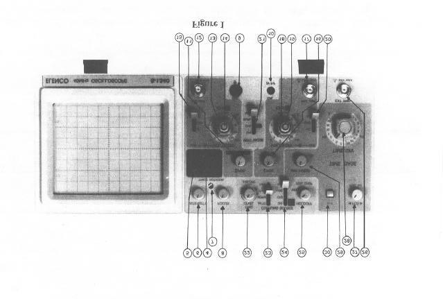
6 OPERATION CONTROLS AND CONNECTORS Refer to Figure 1 and Figure 2 as you read the following paragraphs. The number at the beginning of each paragraph corresponds to the circled number on the illustrations. General 1. Line Voltage and Fuse label - Lists the acceptable voltage range and fuse rating for each of die four ways that you can install the line voltage selector plug. 2. AC line voltage selector plug and fuse Allows you to match your AC line voltage to the oscilloscope's power transformer by aligning the arrowhead on the rear panel with the appropriate voltage (110, 125, 220, or 240) on the selector plug. The fuse is on the inside of the selector plug. CAUTION: For continued safety, replace the fuse with a properly rated part. Refer to the rear panel and the Parts List. 3. AC input socket - Receptacle for ft 3-wire AC line cord. 4. POWER - Turns the Oscilloscope on and off. 5. "ON" LED - Lights when the POWER switch is pushed "ON" 6. INTENSITY - Clockwise rotation increases the brightness of the display. Adjust the brightness for your lighting conditions. Refocusing may be necessary when the intensity is changed. CAUTION: Do not allow a bright spot to remain on the screen; it could damage the CRT. 7. TRACE ROT - This is a seldom-used control that aligns the trace to the horizontal graticule lines. Readjustment may be required in the presence of magnetic materials, electromagnetic fields, or after moving the Oscilloscope to a new location. 8. FOCUS - Varies the size of the electron beam striking the screen. Adjust for the sharpest display. 9. GND - Provides a chassis ground that is connected to the 3-wire AC line cord (earth) ground. 10. CAL 2Vp -p - Provides a 1 khz square wave signal useful for frequency compensation of probes, checking amplifier gain, etc. Channel A (CHA) Controls 11. POSITION - Positions the CHA trace vertically on the CRT screen. NOTE: This control is inoperative for the X-Y mode. PULL ALT TRIG - For dual trace signals, selects the triggering mode in which each sweep alternates between channel A (CHA) and channel B (CHB) signals as separate triggering sources MΩ 25 pf - This BNC connector is the CHA input. It is also the X (horizontal) input during X-Y mode operation. 13. VOLTS/DIV - Each position of this attenuator switch is marked with a number that indicates the peak-to-peak input voltage required to produce a peakto-peak deflection of one major division (1 cm) on the screen's graticule when the VAR PULL 5X MAG control is set to its CAL'D (fully clockwise) position and pushed in. 14. VAR PULL X5 MAG - This control is normally set to its CAL'D position (fully clockwise), where the VOLTS/DIV switch positions are calibrated. The vertical gain decreases as the control is turned counterclockwise, permitting the size of the vertical pattern to be adjusted in a continuous manner between the selected range and the next higher range. * When this knob is pulled out the vertical amplifier sensitivity is increased by a factor of five. * 15. AC-GND-DC - This switch has three positions: AC: The input signal is capacitively coupled to the vertical amplifier and any DC component is blocked. The low-frequency limit is about 10 Hz (at -3 db). GND: Disconnects (opens) the input circuit and grounds the vertical amplifier input. Use this position when you wish to set the trace to a desired reference baseline without disconnecting the input signal. DC: Both the DC and AC components of the input signal are applied to the vertical amplifier input.
7 Channel B (CHB) Controls 16. POSITION - Positions the CHB trace vertically on the CRT screen. It is also the Y (vertical) position control in the X-Y mode. PULL INV - When the POSITION control is pulled out, the CHB trace (AC plus DC) is inverted MΩ 25 pf - This BNC connector is the CHB input. It is also the Y (vertical) input during X-Y operation. 18. VOLTS/DIV - Each position of this attenuator switch is marked with a number that indicates the peak-to-peak input voltage required to produce a peakto-peak deflection of one major division (1 cm) on do screen's graticule when the VAR PULL X5 MAG control is set to its CAL'D position (fully clockwise) and pushed in. 19. VAR PULL X5 MAG - This control is normally set to its CAL'D position (fully clockwise), where the VOLTS/DIV switch positions are calibrated. The vertical gain decreases as the control is turned counterclockwise, permitting the size of the vertical pattern to be adjusted in a continuous manner between the selected range and the next higher range. * When this knob is pulled out, the vertical amplifier sensitivity is increased by a factor of five. * 20. AC-GND-DC - This switch has three positions: AC: The input signal is capacitively coupled to the vertical amplifier and any DC comp onent is blocked. The low-frequency limit is about 10 Hz (at -3 db). GND: Disconnects (opens) the input circuit and grounds the vertical amplifier input. Use this position when you wish to set the trace to a desired reference baseline without disconnecting the input signal. DC: Both the DC and AC components of the input signal are applied to the vertical amplifier input. Both Channels Control 21. VERT MODE-This switch has four positions: CHA: Displays the Channel A trace only. CHB: Displays the Channel B trace only. DUAL: Displays both the CHA and CHB traces. The traces are normally alternating; that is, CHB is swept at the end of the CHA sweep and vice versa. You can select a chopping mode by pulling the HOLDOFF control. In this mode, the trace is quickly switched between the CHA and CHB inputs (at a 500 khz rate) to enhance the viewing of signals with low sweep rates and to verify timing relationships between signals at low and medium sweep rates. ADD: With the PULL INV switch for CHB pushed in, displays the algebraic sum of the CHA and CHB signals (that is, CHA + CHB). With the PULL INV switch for CHB pulled out, displays the algebraic difference between the CHA and CHB signals (that is, CHA - CHB). Triggering Controls 22. TRIGLEVEL- Adjust to select the starting point at which the sweep is triggered. Turn the control fully counterclockwise for a fixed (0 volts) level. PULL SLP (-) - When pushed in, the TRIG LEVEL adjustment covers the rising (positive) slope; when pulled out, it covers the falling (negative) slope. 23. COUPLING - Selects the triggering mode as follows: AUTO: For normal triggering. The sweep freeruns in the absence of a sufficient triggering signal. NORM: For normal triggering. No sweep occurs if the triggering signal does not meet the TRIG LEVEL amplitude and slope settings. TV-V: Rejects DC and high-frequency sync signals in a composite video signal. TV-H: Rejects DC and low-frequency sync signals in a composite video signal. 24. SOURCE - Selects the triggering source signal as follows: CHA: Channel A signal. CHB: Channel B signal LINE: AC line-frequency. EXT: The signal applied to the EXT TRIG connector.
8 25. HOLDOFF - Use this control if the measured signal waveform is made up of complex repetitive cycles and the TRIG LEVEL control (22) alone is not sufficient to attain a stable waveform display. PULL CHOP - With this switch out, the Oscilloscope displays dual-trace signals by chopping (switching back and forth between traces) during the sweep - most useful at low sweep rates. With the switch in, the Oscilloscope alternates by showing the CHA trace on one sweep, and the CHB trace on another sweep - most useful at higher sweep rates. 26. EXT TRIG - Connect an external triggering signal to this connector. To use it, first set the SOURCE switch (24) to the EXT position. Horizontal/Time Base Controls 27. POSITION - Positions the trace horizontally on the CRT screen. It is also the X (horizontal) position control in the X-Y mode. PULL X10 MAG - When the POSITION control is pulled out, the horizontal trace is expanded by a factor of ten. 28. TIME/DIV - Selects the time setting for the beam to sweep one major division (1 cm) on the CRT screen. 29. VAR - Provides a continuous adjustment of the sweep time between the selected range and the next slower range. The time base is calibrated with the knob set to its CAL'D position (fully clockwise). X-Y Mode Controls 30. X-Y- With this switch pushed in, the SOURCE switch (24) set to CHA, and the VERT MODE switch (21) set to CHB, the instrument operates as an X-Y oscilloscope. *The bandwidth is reduced when you use this control or switch. X-Y MODE OPERATION With the X-Y switch pushed in, the SOURCE switch set to CHA, and the VERT MODE switch set to CHB, the instrument will operate as an X-Y oscilloscope. CHA signals produce a horizontal deflection (X) while CHB signals produce a vertical deflection (Y). The CHB POSITION control adjusts the vertical (Y) position, and the CHA POSITION control adjusts fthorizontal (X) position. The AC-GND-DC and VOLTS/ DIV switches for CHA and CHB and the PULL INV switch for CHB operate as previously described. Using the X-Y mode will produce trapezoidal waveforms for evaluating AM modulation (X is the modulating signal and Y is the modulated output) and Lissajous waveforms for evaluating frequency and phase relationships of two signals. You can also use this mode to connect the Oscilloscope as the voltageversus-current display for a semiconductor curve tracer. Refer to the curve tracer Manual for instructions. Frequency Measurements Set the X-Y, SOURCE, and VERT MODE switches for X-Y operation as explained above. Then connect a standard frequency signal to the CHA input connector and the unknown signal to the CHB input connector. The display will be a Lissajous figure, examples of which are shown in Figure 15.
9 LISSAJOUS FIGURES When two sinusoidal signals at the same radian frequency ω but with a phase difference φ are applied to the x and y input of an oscilloscope respectively, a waveform called a Lissajous figure is displayed. Usually it is an ellipse and a typical one is shown in Fig. 5. Fig. 5 A Lissajous figure can be used to measure the phase difference φ. With the notations defined in Fig. 5, then φ = sin -1 (A/B) * * To prove this, assume that, without the loss of generality, v x (t) = V x cos(ωt) and v y (t) = V y cos(ωt - φ). According to Fig. 5, A is equal to the magnitude of v y (t) when v x (t)=0. Therefore A = V y cos(ωt-φ) = V y (cos(ωt)cos(φ) + sin(ωt)sin(φ)) = V y sin(φ)..(1) since cos(ωt )= 0, sin(ωt )= 1 when v x (t) = 0. Again, B is defined as the maximum value of v y (t). Therefore B = V y..(2) From (1) and (2) φ = sin -1 (A/B). Note that the measuring of φ by a Lissajous figure is independent of the magnitudes of v x (t) and v y (t). Also note that, according to Fig. 5, C = V x. Therefore the Lissajous figure provides all the information about these two signals except their radian frequency ω.
Oscilloscope Measurements
 PC1143 Physics III Oscilloscope Measurements 1 Purpose Investigate the fundamental principles and practical operation of the oscilloscope using signals from a signal generator. Measure sine and other waveform
Sirindhorn International Institute of Technology Thammasat University at Rangsit
 Sirindhorn International Institute of Technology Thammasat University at Rangsit School of Information, Computer and Communication Technology COURSE : ECS 210 Basic Electrical Engineering Lab INSTRUCTOR
Electric Circuit II Lab Manual Session #1
 Department of Electrical Engineering Electric Circuit II Lab Manual Session #1 Subject Lecturer Dr. Yasser Hegazy Name:-------------------------------------------------- Group:--------------------------------------------------
General Construction & Operation of Oscilloscopes
 Science 14 Lab 2: The Oscilloscope Introduction General Construction & Operation of Oscilloscopes An oscilloscope is a widely used device which uses a beam of high speed electrons (on the order of 10 7
Experiment 5 The Oscilloscope
 Experiment 5 The Oscilloscope Vision is the art of seeing things invisible. J. Swift (1667-1745) OBJECTIVE To learn to operate a cathode ray oscilloscope. THEORY The oscilloscope, or scope for short, is
THE CATHODE RAY OSCILLOSCOPE
 The Department of Engineering SS1.2 THE CATHODE RAY OSCILLOSCOPE Objectives The objective of this laboratory is for you to familiarise yourself with the operation of a cathode ray oscilloscope (CRO). Once
Oscilloscope. 1 Introduction
 Oscilloscope Equipment: Capstone, BK Precision model 2120B oscilloscope, Wavetek FG3C function generator, 2-3 foot coax cable with male BNC connectors, 2 voltage sensors, 2 BNC banana female adapters,
University of TN Chattanooga Physics1040L 8/29/2012 PHYSICS 1040L LAB LAB 6: USE OF THE OSCILLOSCOPE
 PHYSICS 1040L LAB LAB 6: USE OF THE OSCILLOSCOPE Object: To become familiar with the operation of the oscilloscope and be able to use an oscilloscope for: 1. Measuring the frequency of an oscillator, 2.
Oscilloscope and Function Generators
 MEHRAN UNIVERSITY OF ENGINEERING AND TECHNOLOGY, JAMSHORO DEPARTMENT OF ELECTRONIC ENGINEERING ELECTRONIC WORKSHOP # 02 Oscilloscope and Function Generators Roll. No: Checked by: Date: Grade: Object: To
BK PRECISION INSTRUCTION MANUAL. MODELS 2120B and 2125A. 30 MHz DUAL-TRACE OSCILLOSCOPES + PRECISION
 + PRECISION BK INSTRUCTION MANUAL MODELS 2120B and 2125A 30 MHz DUAL-TRACE OSCILLOSCOPES BK PRECISION + TEST INSTRUMENT SAFETY WARNING Normal use of test equipment exposes you to a certain amount of danger
Cornerstone Electronics Technology and Robotics Week 21 Electricity & Electronics Section 10.5, Oscilloscope
 Cornerstone Electronics Technology and Robotics Week 21 Electricity & Electronics Section 10.5, Oscilloscope Field trip to Deerhaven Generation Plant: Administration: o Prayer o Turn in quiz Electricity
Exp. #2-6 : Measurement of the Characteristics of,, and Circuits by Using an Oscilloscope
 PAGE 1/14 Exp. #2-6 : Measurement of the Characteristics of,, and Circuits by Using an Oscilloscope Student ID Major Name Team No. Experiment Lecturer Student's Mentioned Items Experiment Class Date Submission
EE 201 Function / Arbitrary Waveform Generator and Oscilloscope Tutorial
 EE 201 Function / Arbitrary Waveform Generator and Oscilloscope Tutorial 1 This is a programmed learning instruction manual. It is written for the Agilent DSO3202A Digital Storage Oscilloscope. The prerequisite
Laboratory 3 (drawn from lab text by Alciatore)
") Laboratory 3 (drawn from lab text by Alciatore) The Oscilloscope Required Components: 1 10 resistor 2 100 resistors 2 lk resistors 1 2k resistor 2 4.7M resistors 1 0.F capacitor 1 0.1 F capacitor 1 1.0uF
Laboratory 3 (drawn from lab text by Alciatore) The Oscilloscope Required Components: 1 10 resistor 2 100 resistors 2 lk resistors 1 2k resistor 2 4.7M resistors 1 0.F capacitor 1 0.1 F capacitor 1 1.0uF
30 MHz Oscilloscope Scientech 801C
 30 MHz Oscilloscope Scientech 801C Learning Material Ver. 1.1 An ISO 9001:2008 company Scientech Technologies Pvt. Ltd. 94, Electronic Complex, Pardesipura, Indore - 452 010 India, + 91-731 4211100, :
TEST INSTRUMENT SAFETY WARNING
 TEST INSTRUMENT SAFETY WARNING Normal use of test equipment exposes you to a certain amount of danger from electrical shock because testing must often be performed where exposed high voltage is present.
2 Oscilloscope Familiarization
 Lab 2 Oscilloscope Familiarization What You Need To Know: Voltages and currents in an electronic circuit as in a CD player, mobile phone or TV set vary in time. Throughout the course you will investigate
Physics 323. Experiment # 1 - Oscilloscope and Breadboard
 Physics 323 Experiment # 1 - Oscilloscope and Breadboard Introduction In order to familiarise yourself with the laboratory equipment, a few simple experiments are to be performed. References: XYZ s of
Operating Manual Ver 1.1
 Oscilloscope Caddo 802 with Logic Scope Operating Manual Ver 1.1. An ISO 9001 : 2000 company 94-101, Electronic Complex, Pardeshipura Indore - 452 010 India Tel : 91-731-2570301/02, 4211100 Fax : 91-731-2555643
ENGR 210 Lab 6 Use of the Function Generator & Oscilloscope
 ENGR 210 Lab 6 Use of the Function Generator & Oscilloscope In this laboratory you will learn to use two additional instruments in the laboratory, namely the function/arbitrary waveform generator, which
EECE208 INTRO To ELECTRICAL ENG LAB. LAB 2. Instrumentation
 EECE208 INTRO To ELECTRICAL ENG LAB Dr. Charles Kim LAB 2. Instrumentation Objectives A brief description of the equipment (Oscilloscope, Function Generator, Power Supply, and Digital Multimeter) and its
PHYSICS 171 UNIVERSITY PHYSICS LAB II. Experiment 4. Alternating Current Measurement
 PHYSICS 171 UNIVERSITY PHYSICS LAB II Experiment 4 Alternating Current Measurement Equipment: Supplies: Oscilloscope, Function Generator. Filament Transformer. A sine wave A.C. signal has three basic properties:
EXPERIMENT NUMBER 2 BASIC OSCILLOSCOPE OPERATIONS
 1 EXPERIMENT NUMBER 2 BASIC OSCILLOSCOPE OPERATIONS The oscilloscope is the most versatile and most important tool in this lab and is probably the best tool an electrical engineer uses. This outline guides
Test No. 1. Introduction to Scope Measurements. Report History. University of Applied Sciences Hamburg. Last chance!! EEL2 No 1
 University of Applied Sciences Hamburg Group No : DEPARTMENT OF INFORMATION ENGINEERING Laboratory for Instrumentation and Measurement L: in charge of the report Test No. Date: Assistant A2: Professor:
Lab 0: Orientation. 1 Introduction: Oscilloscope. Refer to Appendix E for photos of the apparatus
 Lab 0: Orientation Major Divison 1 Introduction: Oscilloscope Refer to Appendix E for photos of the apparatus Oscilloscopes are used extensively in the laboratory courses Physics 2211 and Physics 2212.
CHAPTER 6. Motor Driver
 CHAPTER 6 Motor Driver In this lab, we will construct the circuitry that your robot uses to drive its motors. However, before testing the motor circuit we will begin by making sure that you are able to
LAB 7: THE OSCILLOSCOPE
 LAB 7: THE OSCILLOSCOPE Equipment List: Dual Trace Oscilloscope HP function generator HP-DMM 2 BNC-to-BNC 1 cables (one long, one short) 1 BNC-to-banana 1 BNC-probe Hand-held DMM (freq mode) Purpose: To
OSCILLOSCOPES. Oscilloscopes CS-5300 SERIES RS-232C OPTION OPTION CS-5370P/5370/5350 FEATURES OUTLINE. Photo: CS-5370P
 Oscilloscopes 100MHz 2-Channel Programmable Oscilloscope ( With Digital Readout / Cursor) CS-5370P CS-5370 100MHz 3-Channel Oscilloscope ( With Digital Readout / Cursor) 50MHz 3-Channel Oscilloscope (
The University of Jordan Mechatronics Engineering Department Electronics Lab.( ) Experiment 1: Lab Equipment Familiarization
 Experiment 1: Lab Equipment Familiarization") The University of Jordan Mechatronics Engineering Department Electronics Lab.(0908322) Experiment 1: Lab Equipment Familiarization Objectives To be familiar with the main blocks of the oscilloscope and
The University of Jordan Mechatronics Engineering Department Electronics Lab.(0908322) Experiment 1: Lab Equipment Familiarization Objectives To be familiar with the main blocks of the oscilloscope and
Sonoma State University Department of Engineering Science Spring 2017
 EE 110 Introduction to Engineering & Laboratory Experience Saeid Rahimi, Ph.D. Lab 4 Introduction to AC Measurements (I) AC signals, Function Generators and Oscilloscopes Function Generator (AC) Battery
30MHz Dual Trace Oscilloscope
 30MHz Dual Trace Oscilloscope Model 72-6802 USER MANUAL This manual contains proprietary information, which is protected by copyrights. All rights are reserved. No part of this manual may be photocopied,
EECE208 INTRO To ELECTRICAL ENG LAB. LAB 2. Instrumentation
 EECE208 INTRO To ELECTRICAL ENG LAB Dr. Charles Kim LAB 2. Instrumentation Objectives A brief description of the equipment (Oscilloscope, Function Generator, Power Supply, and Digital Multimeter) and its
THE XYZs OF USING A SCOPE
 TEK MULTI-PURPOSE OSCILLOSCOPES OSCILLOSCOPE PRIMER THE XYZs OF USING A SCOPE Tektronix COMMITTED TO EXCELLENCE CONTENTS INTRODUCTION 1 PART II. Making Measurements 19 PART I. Scopes, Controls, & Probes
The Oscilloscope. Vision is the art of seeing things invisible. J. Swift ( ) OBJECTIVE To learn to operate a digital oscilloscope.
 OBJECTIVE To learn to operate a digital oscilloscope.") The Oscilloscope Vision is the art of seeing things invisible. J. Swift (1667-1745) OBJECTIVE To learn to operate a digital oscilloscope. THEORY The oscilloscope, or scope for short, is a device for drawing
The Oscilloscope Vision is the art of seeing things invisible. J. Swift (1667-1745) OBJECTIVE To learn to operate a digital oscilloscope. THEORY The oscilloscope, or scope for short, is a device for drawing
Notes on Experiment #1
 Notes on Experiment #1 Bring graph paper (cm cm is best) From this week on, be sure to print a copy of each experiment and bring it with you to lab. There will not be any experiment copies available in
OSCILLOSCOPES. Oscilloscopes CS-5400 SERIES CS-5400/5450 FEATURES OUTLINE CS-5400
 99 Washington Street Melrose, MA 02176 Fax 781-665-0780 TestEquipmentDepot.com Oscilloscopes 100MHz 3-Channel Oscilloscope (With Digital Readout / Cursor) CS-5400 100MHz 3-Channel Oscilloscope CS-5405
Name Date: Course number: MAKE SURE TA & TI STAMPS EVERY PAGE BEFORE YOU START EXPERIMENT 10. Electronic Circuits
 Laboratory Section: Last Revised on September 21, 2016 Partners Names: Grade: EXPERIMENT 10 Electronic Circuits 1. Pre-Laboratory Work [2 pts] 1. How are you going to determine the capacitance of the unknown
FYSP1110/K1 (FYSP110/K1) USE OF AN OSCILLOSCOPE
 USE OF AN OSCILLOSCOPE") FYSP1110/K1 (FYSP110/K1) USE OF AN OSCILLOSCOPE 1 Introduction In this exercise you will get basic knowledge about how to use an oscilloscope. You ll also measure properties of components, which you are
FYSP1110/K1 (FYSP110/K1) USE OF AN OSCILLOSCOPE 1 Introduction In this exercise you will get basic knowledge about how to use an oscilloscope. You ll also measure properties of components, which you are
DEPARTMENT OF INFORMATION ENGINEERING. Test No. 1. Introduction to Scope Measurements. 1. Correction. Term Correction. Term...
 2. Correction. Correction Report University of Applied Sciences Hamburg Group No : DEPARTMENT OF INFORMATION ENGINEERING Laboratory for Instrumentation and Measurement L: in charge of the report Test No.
Oscilloscope. Analog Oscilloscope Operation Manual. 99 Washington Street Melrose, MA Phone Toll Free
 99 Washington Street Melrose, MA 02176 Phone 781-665-1400 Toll Free 1-800-517-8431 Visit us at www.testequipmentdepot.com Oscilloscope Analog Oscilloscope Operation Manual Oscilloscope Analog Oscilloscope
Analog Oscilloscope Operation Manual
 Oscilloscope OS-5000series OS-5040B: 40MHz Analog Oscilloscope Operation Manual Oscilloscope OS-5000series OS-5040B: 40MHz Analog Oscilloscope Operation Manual DECLARATION OF CONFORMITY According to ISO/IEC
Laboratory Equipment Instruction Manual 2011
 University of Toronto Department of Electrical and Computer Engineering Instrumentation Laboratory GB341 Laboratory Equipment Instruction Manual 2011 Page 1. Wires and Cables A-2 2. Protoboard A-3 3. DC
EC Declaration of Conformity
 99 Washington Street Melrose, MA 02176 Phone 781-665-1400 Toll Free 1-800-571-8431 Visit us at www.testequipmentdepot.com We EC Declaration of Conformity GOOD WILL INSTRUMENT CO., LTD. (1) No. 95-11, Pao-Chung
Laboratory Exercise 6 THE OSCILLOSCOPE
 Introduction Laboratory Exercise 6 THE OSCILLOSCOPE The aim of this exercise is to introduce you to the oscilloscope (often just called a scope), the most versatile and ubiquitous laboratory measuring
EXPERIMENT 1 PRELIMINARY MATERIAL
 EXPERIMENT 1 PRELIMINARY MATERIAL BREADBOARD A solderless breadboard, like the basic model in Figure 1, consists of a series of square holes, and those columns of holes are connected to each other via
Ahsanullah University of Science and Technology
 Ahsanullah University of Science and Technology Department of Electrical and Electronic Engineering AU ST /E EE LABORATORY MANUAL FOR ELECTRICAL AND ELECTRONIC SESSIONAL COURSE Student Name : Student ID
POLYTECHNIC UNIVERSITY Electrical Engineering Department. EE SOPHOMORE LABORATORY Experiment 3 The Oscilloscope
 POLYTECHNIC UNIVERSITY Electrical Engineering Department EE SOPHOMORE LABORATORY Experiment 3 The Oscilloscope Modified for Physics 18, Brooklyn College I. Overview of the Experiment The main objective
SAFETY TERMS AND SYMBOLS
 CONTENTS PAGE 1. PRODUCT INTRODUCTION... 1-1.Description. 1-2.Feature... 1 1 2 2. TECHNICAL SPECIFICATION.. 4 3. PRECAUTIONS BEFORE OPERATION... 3-1.Unpacking the instrument... 3-2.Checking the Line Voltage...
Getting Started. MSO/DPO Series Oscilloscopes. Basic Concepts
 Getting Started MSO/DPO Series Oscilloscopes Basic Concepts 001-1523-00 Getting Started 1.1 Getting Started What is an oscilloscope? An oscilloscope is a device that draws a graph of an electrical signal.
How to Setup and Use an Oscilloscope
 How to Setup and Use an Oscilloscope An oscilloscope is a device that is used to measure voltage with respect to time. Oscilloscopes are essential pieces of test equipment used in the development and testing
ME 365 EXPERIMENT 1 FAMILIARIZATION WITH COMMONLY USED INSTRUMENTATION
 Objectives: ME 365 EXPERIMENT 1 FAMILIARIZATION WITH COMMONLY USED INSTRUMENTATION The primary goal of this laboratory is to study the operation and limitations of several commonly used pieces of instrumentation:
AME140 Lab #2 INTRODUCTION TO ELECTRONIC TEST EQUIPMENT AND BASIC ELECTRONICS MEASUREMENTS
 INTRODUCTION TO ELECTRONIC TEST EQUIPMENT AND BASIC ELECTRONICS MEASUREMENTS The purpose of this document is to guide students through a few simple activities to increase familiarity with basic electronics
EE EXPERIMENT 1 (2 DAYS) BASIC OSCILLOSCOPE OPERATIONS INTRODUCTION DAY 1
 BASIC OSCILLOSCOPE OPERATIONS INTRODUCTION DAY 1") EE 2101 - EXPERIMENT 1 (2 DAYS) BASIC OSCILLOSCOPE OPERATIONS INTRODUCTION The oscilloscope is the most versatile and most important tool in this lab and is probably the best tool an electrical engineer
EE 2101 - EXPERIMENT 1 (2 DAYS) BASIC OSCILLOSCOPE OPERATIONS INTRODUCTION The oscilloscope is the most versatile and most important tool in this lab and is probably the best tool an electrical engineer
ECE 53A: Fundamentals of Electrical Engineering I
 ECE 53A: Fundamentals of Electrical Engineering I Laboratory Assignment #1: Instrument Operation, Basic Resistor Measurements and Kirchhoff s Laws Fall 2007 General Guidelines: - Record data and observations
PHUONGLAI.COM SAFETY TERMS AND SYMBOLS. 1. PRODUCT INTRODUCTION Description. 1-2.Feature...
 CONTENTS PAGE 1. PRODUCT INTRODUCTION... 1-1.Description. 1-2.Feature... 1 1 2 SAFETY TERMS AND SYMBOLS These terms may appear in this manual or on the product: 2. TECHNICAL SPECIFICATION.. 4 3. PRECAUTIONS
DEPARTMENT OF THE ARMY TECHNICAL BULLETIN
 *TB 9-6625-2240-35 DEPARTMENT OF THE ARMY TECHNICAL BULLETIN CALIBRATION PROCEDURE FOR OSCILLOSCOPE OS261U (TEKTRONIX, TYPE 475), OS261A(V)1U (TEKTRONIX, TYPE 475 OPTION 7), OS261B(V)1U (TEKTRONIX, TYPE
Test No. 2. Advanced Scope Measurements. History. University of Applied Sciences Hamburg. Last chance!! EEL2 No 2
 University of Applied Sciences Hamburg Group No : DEPARTMENT OF INFORMATION ENGINEERING Laboratory for Instrumentation and Measurement L1: in charge of the report Test No. 2 Date: Assistant A2: Professor:
SAFETY TERMS AND SYMBOLS
 CONTENTS PAGE 1. PRODUCT INTRODUCTION... 1-1.Description. 1-2.Feature... 1 1 2 2. TECHNICAL SPECIFICATION.. 4 3. PRECAUTIONS BEFORE OPERATION... 3-1.Unpacking the instrument... 3-2.Checking the Line Voltage...
5MHz FUNCTION GENERATOR
 5MHz FUNCTION GENERATOR MODEL GF-8056 User s Manual Elenco TM Electronics, Inc. Copyright 2004 by Elenco TM Electronics, Inc. All rights reserved. 753117 No part of this book shall be reproduced by any
Instruction Manual for AT7328/7340 Dual Channel Oscilloscope
 Instruction Manual for AT7328/7340 Dual Channel Oscilloscope Introduction 1. AT7328 /7340 Series Dual Channel Oscilloscope, Maximum sensibility is 5mV/div, maximum sweep speed is 0.2s/div, and can be expanded
5MHz FUNCTION GENERATOR
 5MHz FUNCTION GENERATOR MODEL GF-8056 99 Washington Street Melrose, MA 02176 Phone 781-665-1400 Toll Free 1-800-517-8431 Visit us at www.testequipmentdepot.com User s Manual Elenco TM Electronics, Inc.
CIRCUIT-TEST ELECTRONICS
 USER'S MANUAL Sweep Function Generator with Counter SWF-8030 CIRCUIT-TEST ELECTRONICS www.circuittest.com TABLE OF CONTENTS SAFETY INFORMATION...page 3 INTRODUCTION... 4 SPECIFICATIONS... 5 FRONT PANEL
PHYSICS 326 LAB # 1: The Oscilloscope and Signal Generators 1/6
 PHYSICS 326 LAB # 1: The Oscilloscope and Signal Generators 1/6 PURPOSE: To be sure that each student begins the course with at least the minimum required knowledge of two instruments which we will be
Artisan Technology Group is your source for quality new and certified-used/pre-owned equipment
 Artisan Technology Group is your source for quality new and certified-used/pre-owned equipment FAST SHIPPING AND DELIVERY TENS OF THOUSANDS OF IN-STOCK ITEMS EQUIPMENT DEMOS HUNDREDS OF MANUFACTURERS SUPPORTED
2 AC and RMS. To pass this lab you must solve tasks 1-2. Tasks 3 and 4 are included in the grading of the course.
 2 AC and RMS Purpose of the lab: to familiarize yourself with the oscilloscope to familiarize yourself with AC voltages and different waveforms to study RMS and average values In this lab, you have the
Artisan Technology Group is your source for quality new and certified-used/pre-owned equipment
 Artisan Technology Group is your source for quality new and certified-used/pre-owned equipment FAST SHIPPING AND DELIVERY TENS OF THOUSANDS OF IN-STOCK ITEMS EQUIPMENT DEMOS HUNDREDS OF MANUFACTURERS SUPPORTED
Performance Characteristics
 The performance characteristics describe the typical performance of the oscilloscope. You will notice that some of the characteristics are marked as tested, these are values that you can verify with the
Exercise 4 - THE OSCILLOSCOPE
 Exercise 4 - THE OSCILLOSCOPE INTRODUCTION You have been exposed to analogue oscilloscopes in the first year lab. As you are probably aware, the complexity of the instruments, along with their importance
LAB INSTRUMENTATION. RC CIRCUITS.
 LAB INSTRUMENTATION. RC CIRCUITS. I. OBJECTIVE a) Becoming accustomed to using the lab instrumentation (voltage supply, digital multimeter, signal generator, oscilloscope) necessary to the experimental
EENG-201 Experiment # 4: Function Generator, Oscilloscope
 EENG-201 Experiment # 4: Function Generator, Oscilloscope I. Objectives Upon completion of this experiment, the student should be able to 1. To become familiar with the use of a function generator. 2.
UCE-DSO210 DIGITAL OSCILLOSCOPE USER MANUAL. FATIH GENÇ UCORE ELECTRONICS REV1
 UCE-DSO210 DIGITAL OSCILLOSCOPE USER MANUAL FATIH GENÇ UCORE ELECTRONICS www.ucore-electronics.com 2017 - REV1 Contents 1. Introduction... 2 2. Turn on or turn off... 3 3. Oscilloscope Mode... 3 3.1. Display
332:223 Principles of Electrical Engineering I Laboratory Experiment #2 Title: Function Generators and Oscilloscopes Suggested Equipment:
 RUTGERS UNIVERSITY The State University of New Jersey School of Engineering Department Of Electrical and Computer Engineering 332:223 Principles of Electrical Engineering I Laboratory Experiment #2 Title:
P a g e 1 ST985. TDR Cable Analyzer Instruction Manual. Analog Arts Inc.
 P a g e 1 ST985 TDR Cable Analyzer Instruction Manual Analog Arts Inc. www.analogarts.com P a g e 2 Contents Software Installation... 4 Specifications... 4 Handling Precautions... 4 Operation Instruction...
Laboratory equipments. Parameters of digital signals.
 Laboratory 1 Laboratory equipments. Parameters of digital signals. 1.1 Objectives This laboratory presents detailed description of the equipments used during the lab and measurement techniques specifically
SAFETY TERMS AND SYMBOLS
 CONTENTS PAGE 1. PRODUCT INTRODUCTION... 1-1.Description. 1-2.Feature... 1 1 2 2. TECHNICAL SPECIFICATIONS 4 3. PRECAUTIONS BEFORE OPERATION.... 3-1.Unpacking the instrument.... 3-2.Checking the Line Voltage....
CRO AIM:- To study the use of Cathode Ray Oscilloscope (CRO).
.") 1. 1 To study CRO. CRO AIM:- To study the use of Cathode Ray Oscilloscope (CRO). Apparatus: - C.R.O, Connecting probe (BNC cable). Theory:An CRO is easily the most useful instrument available for testing
1. 1 To study CRO. CRO AIM:- To study the use of Cathode Ray Oscilloscope (CRO). Apparatus: - C.R.O, Connecting probe (BNC cable). Theory:An CRO is easily the most useful instrument available for testing
EEE1016 Electronics I
 EEE1016 Electronics I: Appendices EEE1016 Electronics I Experiment BE1: Diode Circuits 1.0 Objectives To observe the operations of a half-wave rectifier and a full-wave bridge rectifier To observe the
Agilent 33522A Function Arbitrary Waveform Generator. Tektronix TDS 3012B Oscilloscope
 Agilent 33522A Function/Arbitrary Waveform Generator and Tektronix TDS 3012B Oscilloscope Agilent 33522A Function Arbitrary Waveform Generator The signal source for this lab is the Agilent 33522A Function
electrical noise and interference, environmental changes, instrument resolution, or uncertainties in the measurement process itself.
 MUST 382 / EELE 491 Spring 2014 Basic Lab Equipment and Measurements Electrical laboratory work depends upon various devices to supply power to a circuit, to generate controlled input signals, and for
Massachusetts Institute of Technology Department of Electrical Engineering and Computer Science Circuits and Electronics Fall 2004
 Massachusetts Institute of Technology Department of Electrical Engineering and Computer Science 6.002 - Circuits and Electronics Fall 2004 Lab Equipment Handout (Handout F04-009) Prepared by Iahn Cajigas
NEW. ANALOG OSCILLOSCOPE Model KM MHz KM MHz TRIGGERING SYSTEM: ELECTRICAL SPECIFICATIONS : X-Y OPERATION: OTHERS :
 An ISO 9001:2008 Company ANALOG OSCILLOSCOPE Model KM-20-10 - 20MHz KM 060-60MHz FEATURE : NEW Dual channels / dual traces, X-Y mode 6 display, high brightness oscilloscope tube High sensitivity triggering,
Appendix A: Laboratory Equipment Manual
 Appendix A: Laboratory Equipment Manual 1. Introduction: This appendix is a manual for equipment used in experiments 1-8. As a part of this series of laboratory exercises, students must acquire a minimum
MODELLING AN EQUATION
 MODELLING AN EQUATION PREPARATION...1 an equation to model...1 the ADDER...2 conditions for a null...3 more insight into the null...4 TIMS experiment procedures...5 EXPERIMENT...6 signal-to-noise ratio...11
Faculty of Engineering, Thammasat University
 Faculty of Engineering, Thammasat University Experiment 6: Oscilloscope (For room 506) Objectives: 1. To familiarize you with the Oscilloscope and Function Generator User Manual: Oscilloscope 1 5 9 4 7
DIGITAL STORAGE OSCILLOSCOPES
 99 Washington Street Melrose, MA 02176 Fax 781-665-0780 TestEquipmentDepot.com DIGITAL STORAGE OSCILLOSCOPES Digital Storage Oscilloscope 100MS/s Acquisition (40MS/s 2 Acquisition) 100MHz 2 channel. OUTLINE
LABORATORY 4. Palomar College ENGR210 Spring 2017 ASSIGNED: 3/21/17
 LABORATORY 4 ASSIGNED: 3/21/17 OBJECTIVE: The purpose of this lab is to evaluate the transient and steady-state circuit response of first order and second order circuits. MINIMUM EQUIPMENT LIST: You will
ELECTRONICS LAB. OSCILLOSCOPE
 ELECTRONICS LAB. OSCILLOSCOPE Yrd. Doç. Dr. Taha İMECİ Arş. Gör. Ezgi YAMAÇ Arş. Gör. Ufuk ŞANVER İSTANBUL COMMERCE UNIVERSITY Contents OSCILLOSCOPE... 2 CRT PART... 3 2 VERTICAL CONTROL PART... 4 3 HORIZONTAL
ELECTRONIC DEVICES AND CIRCUITS. Faculty: 1.Shaik.Jakeer Hussain 2.P.Sandeep patil 3.P.Ramesh Babu
 ELECTRONIC DEVICES AND CIRCUITS Faculty: 1.Shaik.Jakeer Hussain 2.P.Sandeep patil 3.P.Ramesh Babu UNIT-I ELECTRON DYNAMICS AND CRO: Motion of charged particles in electric and magnetic fields. Simple problems
Analog Oscilloscope Selection Guide
 Selection Guide Model TOS-2020CH TOS-2020CF TOS-2020CT TOS-2020 TOS-2020FG TOS-2100C TOS-2040CH TOS-2040CF TOS-2040CT TOS-2040 TOS-2040FG TOS-2050CH TOS-205CF TOS-2050CT TOS-2050 TOS-2050FG Max. bandwidth
Oscilloscope calibration Application Note
 Oscilloscope calibration Application Note A guide to oscilloscope calibration using dedicated or multiproduct calibrators User requirements Oscilloscopes are very complex instruments, mainly because of
ORGANIZATIONAL, DIRECT SUPPORT, AND GENERAL SUPPORT MAINTENANCE MANUAL DUAL TIME BASE, TEKTRONIX MODEL 7B92A (NSN )
") ARMY TM 11-6625-2925-24 AIR FORCE TO 33A1-10-242-2 ORGANIZATIONAL, DIRECT SUPPORT, AND GENERAL SUPPORT MAINTENANCE MANUAL DUAL TIME BASE, TEKTRONIX MODEL 7B92A (NSN 6625-01-027-0265) DEPARTMENTS OF THE
ARMY TM 11-6625-2925-24 AIR FORCE TO 33A1-10-242-2 ORGANIZATIONAL, DIRECT SUPPORT, AND GENERAL SUPPORT MAINTENANCE MANUAL DUAL TIME BASE, TEKTRONIX MODEL 7B92A (NSN 6625-01-027-0265) DEPARTMENTS OF THE
THE SINUSOIDAL WAVEFORM
 Chapter 11 THE SINUSOIDAL WAVEFORM The sinusoidal waveform or sine wave is the fundamental type of alternating current (ac) and alternating voltage. It is also referred to as a sinusoidal wave or, simply,
Performance-based assessments for AC circuit competencies
 Performance-based assessments for AC circuit competencies This worksheet and all related files are licensed under the Creative Commons Attribution License, version 1.0. To view a copy of this license,
Parts to be supplied by the student: Breadboard and wires IRLZ34N N-channel enhancement-mode power MOSFET transistor
 University of Utah Electrical & Computer Engineering Department ECE 1250 Lab 3 Electronic Speed Control and Pulse Width Modulation A. Stolp, 12/31/12 Rev. Objectives 1 Introduce the Oscilloscope and learn
The Discussion of this exercise covers the following points:
 Exercise 3-2 Frequency-Modulated CW Radar EXERCISE OBJECTIVE When you have completed this exercise, you will be familiar with FM ranging using frequency-modulated continuous-wave (FM-CW) radar. DISCUSSION
20MHz Dual Trace Oscilloscope MODEL: MC1
 20MHz Dual Trace Oscilloscope MODEL: 72-6800 8272-68000MC1 CONTENTS PAGE 1. GENERAL....... 1-1. Description. 1-2.Feature 2. TECHNICAL SPECIFICATIONS.. 2 3. PRECAUTIONS BEFORE OPERATING THE OSCILLOSCOPE.....
OPERATING AND MAINTENANCE MANUAL
 5Hz to 1MHz WIDE RANGE FULLY AUTOMATIC DISTORTION ANALYZER MODEL 6900B SERIAL NO. OPERATING AND MAINTENANCE MANUAL Unit 4, 15 Jonathan Drive, Brockton, MA 02301-5566 Tel: (508) 580-1660; Fax: (508) 583-8989
Introduction to Electronic Equipment
 Introduction to Electronic Equipment INTRODUCTION This semester you will be exploring electricity and magnetism. In order to make your time in here more instructive we ve designed this laboratory exercise
Introduction to oscilloscope. and time dependent circuits
 Physics 9 Intro to oscilloscope, v.1.0 p. 1 NAME: SECTION DAY/TIME: TA: LAB PARTNER: Introduction to oscilloscope and time dependent circuits Introduction In this lab, you ll learn the basics of how to
Appendix A: Specifications
 All specifications apply to the TDS 200-Series Digital Oscilloscopes and a P2100 probe with the Attenuation switch set to 10X unless noted otherwise. To meet specifications, two conditions must first be