Measurement of Resistance and Potentiometers
|
|
|
- Janice Flowers
- 5 years ago
- Views:
Transcription
1 Electrical Measurements International Program Department of Electrical Engineering UNIVERSITAS INDONESIA Measurement of Resistance and Potentiometers Jahroo Renardi Lecturer : Ir. Chairul Hudaya, ST, M.Eng., Ph.D., IPM
2 Outline 4.1 Introduction 4.2 Measurement of Medium Resistances 4.3 Measurement of Low Resistances 4.4 Measurement of High Resistances 4.5 Localisation of Cable Faults 4.6 Exercise
3 Potentiometer 5.1 Introduction 5.2 A Basic dc Potentiometer 5.3 Crompton s dc Potentiometers 5.4 Applications of dc Potentiometers 5.5 AC Potentiometers 5.6 Classification of AC Potentiometers 5.7 Advantages and Disadvantages of AC Potentiometers 5.8 Applications of AC Potentiometer 5.9 Exercise
4 Measurement of Resistance
5 Introduction 1. Low Resistance a. < 1Ω b. Can be found in copper winding in armatures, ammeter shunts, contacts, switches, etc. 2. Medium Resistance a. 1 Ω to 100 kω b. Most of the electrical apparatus used in practice, electronic circuits, carbon resistance and metal film resistors 3. High Resistance a. > 100 kω
6 Measurement of Medium Resistance - Methods Ohmmeter method Voltmeter ammeter method Substitution method Wheatstone bridge method
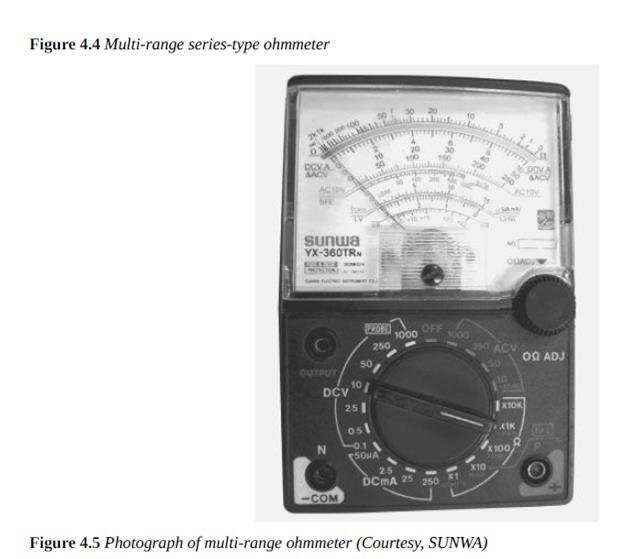
7 Ohmmeter Method give quick and direct readings useful in measurement laboratories as an adjunct to a precision bridge Ohmmeter types: 1. Series Ohmmeter 2. Multirange Series Ohmmeter 3. Shunt-type Ohmmeter
8 Series Ohmmeter
9 Series Ohmmeter A-B shorted, Rx = 0, maximum current flows into the circuit. The shunt resistance R 2 is adjusted so that the meter deflects corresponding to its right most full scale deflection (FSD) position A-B open, Rx =, no current flows. the pointer corresponds to the left most zero current position on the scale Series ohmmeters thus have 0 mark at the extreme right and mark at the extreme left of scale (opposite to those for ammeters and voltmeters).
10 Difficulties in Ohmmeter Ohmmeters are usually powered by batteries, and the battery voltage gradually changes with use and age. Output voltage will decrease Current flows into the ohmmeter will also decrease Ohmmeter no longer point to 0 Ω if A-B is shorted Thus, the reading will become inaccurate
11
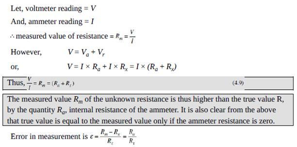
12 Multi-range Series Ohmmeter The additional shunt resistances R3, R4, R7 are used to adjust the meter current to correspond to 0 to FSD scale each time the range of the unknown resistance Rx is changed
13
14 Shunt-type Ohmmeter
15 Shunt-type Ohmmeter A-B shorted, Rx = 0, meter current is 0 A-B open, Rx =, entire current flows through the meter Selecting proper value of R1, this maximum current position of the pointer can be made to read full scale of the meter This position of the pointer is marked as Ω on the scale 0 Ω at the left most position corresponding to zero current Ω at the right most end of the scale corresponding to FSD current.
16
17 Problem - Series Ohmmeter The internal battery has a voltage of 3 V. It is desired to read half scale at a resistance value of 2000 Ω. Calculate: the values of shunt resistance and current limiting series resistance range of values of the shunt resistance to accommodate battery voltage variation in the range 2.7 to 3.1 V.
18
19
20 Volt-Ammeter
21 Volt-Ammeter - Case A ammeter is connected directly with the unknown resistance voltmeter is connected across the series combination of ammeter and the resistance Rx The ammeter measures the true value of current through the resistance The voltmeter measures the sum of voltage drops across the ammeter and the unknown resistance Rx.
22 Volt-Ammeter - Case A
23 Volt-Ammeter - Case B the voltmeter is connected directly across the unknown resistance the ammeter is connected in series with the parallel combination of voltmeter and the resistance Rx The ammeter measures the summation of current flowing through the voltmeter and the unknown resistance Rx.
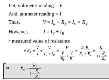
24 Volt-Ammeter - Case B
25 Substitution Method The unknown resistance Rx is measured with respect to the standard variable resistance S
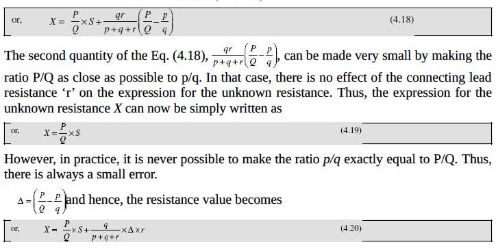
26 Wheatstone Bridge bridge consists of: The Wheatstone four resistance arms, together with a battery (voltage source) and a galvanometer (null detector). R3, R4 = fixed resistance, R2 = known variable Rx = unknown resistance
27 Wheatstone Bridge At balance the following conditions are satisfied: 1. The detector current is zero, i.e., 1D = 0 and thus It = I3 and I2 = I4 2. V B = V C, V AB = V AC and voltage drop in the arm BD equals the voltage drop across the arm CD, i.e., V BD = V CD I1 Rx = I2 R2
28 Wheatstone Bridge
29 Measurement of Low Resistance The methods used for measurement of medium resistances are not suitable for measurement of low resistances. This is due to the fact that resistances of leads and contacts, though small, are appreciable in comparison to the low resistances under measurement. For example, a contact resistance of Ω causes a negligible error when a medium resistance of value say, 100 Ω is being measured, but the same contact resistance would cause an error of 10% while measuring a low resistance of value Ω. Hence special type of construction and techniques need to be used for measurement of low resistances to avoid errors due to leads and contacts. (i) Voltmeter ammeter method (iii) Kelvin s double-bridge method (iv) Potentiometer method.
30 Voltmeter-Ammeter Method
31 Kelvin s Double-Bridge Method
32
33
34 Potentiometer Method
35 Measurement of High Resistance - Loss Charge The unknown resistance R to be measured is connected across the capacitor C and their parallel combination is connected to the dc voltage source. Let the capacitor is initially charged up to a voltage of V while the switch is kept ON. Once the switch is turned OFF, the capacitor starts to discharge through the resistance R. During the discharge process, the voltage v across the capacitor at any instant of time t is given by.
36 Localisation of Cable Faults Underground cables during their operation can experience various fault conditions. Whereas routine standard tests are there to identify and locate faults in high-voltage cables, special procedures, as will be described in this section are required for localisation of cable faults in low distribution voltage level cables. Determination of exact location of fault sections in underground distribution cables is extremely important from the point of view of quick restoration of service without loss of time for repair. The faults that are most likely to occur are ground faults where cable insulation may break down causing a current to flow from the core of the cable to the outer metal sheath or to the earth; or there may be short-circuit faults where a insulation failure between two cables, or between two cores of a multi-core cable results in flow of current between them. Loop tests are popularly used in localisation of the aforesaid types of faults in low voltage cables. These tests can be carried out to localise a ground fault or a short-circuit fault, provided that an unfaulty cable runs along with the faulty cable. Such tests have the advantage that fault resistance does not affect the measurement sensitivity, that the fault resistance is not too high. Loop tests work on the simple principles of a Wheatstone bridge for measurement of unknown resistances.
37 Murray Loop Test
38 Varley Loop Test
39 Potentiometer
40 Introduction A potentiometer is an instrument which is used for measurement of potential difference across a known resistance or between two terminals of a circuit or network of known characteristics. A potentiometer is also used for comparing the emf of two cells. A potentiometer is extensively used in measurements where the precision required is higher than that can be obtained by ordinary deflecting instruments, or where it is required that no current be drawn from the source under test, or where the current must be limited to a small value.
41 Introduction Some important characteristics of potentiometer are the following: A potentiometer measures the unknown voltage by comparing it with a known voltage source rather than by the actual deflection of the pointer. This ensures a high degree of accuracy. As a potentiometer measures using null or balance condition, hence no power is required for the measurement. Determination of voltage using potentiometer is quite independent of the source resistance.
42 Basic DC Potentiometer
43 Crompton s DC Potentiometers
44 Applications of DC Potentiometers Practical uses of dc potentiometers are Measurement of current Measurement of high voltage Measurement of resistance Measurement of power Calibration of voltmeter Calibration of ammeter Calibration of wattmeter
45 Measurement of Current
46 Measurement of High Voltage
47 Measurement of Resistance
48 Measurement of Power
49 Calibration of Voltmeter
50 Callibration of Ammeter
51 Callibration of Wattmeter
52 AC Potentiometers In case of dc potentiometer, only the magnitude of the unknown emf is compared with the standard cell emf, but in ac potentiometer, the magnitude as well as phase angle of the unknown voltage is compared to achieve balance. This condition of ac potentiometer needs modification of the potentiometer as constructed for dc operation. The following points need to be considered for the satisfactory operation of the ac potentiometer: 1. To avoid error in reading, the slide wire and the resistance coil of an ac potentiometer should be noninductive. 2. The reading is affected by stray or external magnetic field, so in the time of measurement they must be eliminated or measured and corresponding correction factor should be introduced. 3. The sources of ac supply should be free from harmonics, because in presence of harmonics the balance may not be achieved. 4. The ac source should be as sinusoidal as possible.
53 Classification of AC Potentiometers There are two general types of ac potentiometers: 1. Polar Potentiometer The unknown emf is measured in polar form, i.e., in terms of its magnitude and relative phase. The magnitude is indicated by one scale and the phase with respect to some reference axis is indicated by another scale. There is provision for reading phase angles up to 360. The voltage is read in the form V θ. Example: Drysdale polar potentiometer 2. Coordinate Potentiometer The unknown emf is measured in Cartesian form. Two components along and perpendicular to some standard axis are measured and indicated directly by two different scales known as in phase (V1 ) and quadrature (V2 ) scales (Figure 5.10). Provision is made in this instrument to read both positive and negative values of voltages so that all angles up to 360 are covered.
54
55 Drysdale Potentiometer Before the ac measurement, the potentiometer is first calibrated by using dc supply for slide wire and standard cell for test terminals T1 and T2. The unknown alternating voltage to be measured is applied across test terminals and the balance is achieved by varying the slide wire contact and the position of the rotor. The ammeter connected in the slide wire circuit gives the magnitude of the unknown emf and the circular dial in the rotor circuit gives the phase angle of it.
56 Gall Coordinate Potentiometer Before using the potentiometer for ac measurements, the current in the inphase potentiometer slide wire is first standardised using a standard dc cell of known value. The vibration galvanometer VG is replaced by a D Arsonval galvanometer. Now the in-phase slide wire current is adjusted to the standard value of 50 ma by varying the rheostat R. This setting is left unchanged for ac calibration; the dc supply is replaced by ac and the D Arsonval galvanometer by the vibration galvanometer.
57 Advantages and Disadvantages of AC Potentiometers Advantages 1. An ac potentiometer is a very versatile instrument. By using shunt and volt ratio box, it can measure wide range of voltage, current and resistances. 2. As it is able to measure phase as well as magnitude of two signals, it is used to measure power, inductance and phase angle of a coil, etc. 3. The principle of ac potentiometer is also incorporated in certain special application like Arnold circuit for the measurement of CT (Current Transformer) errors.
58 Disadvantages 1. A small difference in reading of the dynamometer instrument either in dc or ac calibration brings on error in the alternating current to be set at standard value. 2. The normal value of the mutual inductance M is affected due to the introduction of mutual inductances of various potentiometer parts and so a slight difference is observed in the magnitude of the current of quadrature wire with compared to that in the in phase potentiometer wire. 3. Inaccuracy in the measured value of frequency will also result in the quadrature potentiometer wire current to differ from that of in phase potentiometer wire. 4. The presence of mutual inductances in the various parts of the potentiometer and the inter capacitance, the potential gradient of the wires is affected. 5. Since the standardisation is done on the basis of rms value and balance is obtained dependent upon the fundamental frequency only, therefore, the presence of harmonics in the input signal introduces operating problem and the vibration galvanometer tuned to the fundamental frequency may not show full null position at all.
59 Applications of AC Potentiometer The major applications of the ac potentiometers are 1. Measurement of self-inductance 2. Calibration of voltmeter 3. Calibration of ammeter 4. Calibration of wattmeter
XII PHYSICS INSTRUMENTS] CHAPTER NO. 15 [ELECTRICAL MEASURING MUHAMMAD AFFAN KHAN LECTURER PHYSICS, AKHSS, K
![XII PHYSICS INSTRUMENTS] CHAPTER NO. 15 [ELECTRICAL MEASURING MUHAMMAD AFFAN KHAN LECTURER PHYSICS, AKHSS, K](/thumbs/80/81415743.jpg "XII PHYSICS INSTRUMENTS] CHAPTER NO. 15 [ELECTRICAL MEASURING MUHAMMAD AFFAN KHAN LECTURER PHYSICS, AKHSS, K") XII PHYSICS MUHAMMAD AFFAN KHAN LECTURER PHYSICS, AKHSS, K affan_414@live.com https://promotephysics.wordpress.com [ELECTRICAL MEASURING INSTRUMENTS] CHAPTER NO. 15 MOVING COIL GALVANOMETER An electrical
XII PHYSICS MUHAMMAD AFFAN KHAN LECTURER PHYSICS, AKHSS, K affan_414@live.com https://promotephysics.wordpress.com [ELECTRICAL MEASURING INSTRUMENTS] CHAPTER NO. 15 MOVING COIL GALVANOMETER An electrical
ELECTRICAL MEASUREMENTS
 R10 Set No: 1 1. a) Derive the expression for torque equation for a moving iron attraction type instrument and comment up on the nature of scale [8] b) Define the terms current sensitivity, voltage sensitivity
SIDDHARTH GROUP OF INSTITUTIONS :: PUTTUR (AUTONOMOUS) Siddharth Nagar, Narayanavanam Road QUESTION BANK (DESCRIPTIVE)
 Siddharth Nagar, Narayanavanam Road QUESTION BANK (DESCRIPTIVE)") SIDDHARTH GROUP OF INSTITUTIONS :: PUTTUR (AUTONOMOUS) Siddharth Nagar, Narayanavanam Road 517583 QUESTION BANK (DESCRIPTIVE) Suject : Electrical & Electronic Measurements(16EE224) Year & Sem: III-B.Tech
SIDDHARTH GROUP OF INSTITUTIONS :: PUTTUR (AUTONOMOUS) Siddharth Nagar, Narayanavanam Road 517583 QUESTION BANK (DESCRIPTIVE) Suject : Electrical & Electronic Measurements(16EE224) Year & Sem: III-B.Tech
Electronic Measurements & Instrumentation. 1. Draw the Maxwell s Bridge Circuit and derives the expression for the unknown element at balance?
 UNIT -6 1. Draw the Maxwell s Bridge Circuit and derives the expression for the unknown element at balance? Ans: Maxwell's bridge, shown in Fig. 1.1, measures an unknown inductance in of standard arm offers
MEASUREMENTS & INSTRUMENTATION ANALOG AND DIGITAL METERS
 MEASUREMENTS & INSTRUMENTATION ANALOG AND DIGITAL METERS ANALOG Metering devices Provides monotonous (continuous) movement. ELECTRICAL MEASURING INSTRUMENTS ANALOG METERS A d Arsonval galvanometer (Moving
Bhoj Reddy Engineering College for Women, Hyderabad Department of Electronics and Communication Engineering Electrical and Electronics Instrumentation
 Bhoj Reddy Engineering College for Women, Hyderabad Department of Electronics and Communication Engineering Electrical and Electronics Instrumentation Academic Year: 2016-17 III B Tech II Semester Branch:
SAMPLE OF THE STUDY MATERIAL PART OF CHAPTER 2 Measurements of Basic Electrical Quantities 1 (Current Voltage, Resistance)
") SAMPLE OF THE STUDY MATERIAL PART OF CHAPTER 2 Measurements of Basic Electrical Quantities 1 (Current Voltage, Resistance) 2.1 Indicating Instruments Analog Instruments: An analog device is one in which
SAMPLE OF THE STUDY MATERIAL PART OF CHAPTER 2 Measurements of Basic Electrical Quantities 1 (Current Voltage, Resistance) 2.1 Indicating Instruments Analog Instruments: An analog device is one in which
Sine waves by far the most important form of alternating quantity important properties are shown below
 AC DC METERS 1 Sine waves by far the most important form of alternating quantity important properties are shown below 2 Average value of a sine wave average value over one (or more) cycles is clearly zero
UNIT II MEASUREMENT OF POWER & ENERGY
 UNIT II MEASUREMENT OF POWER & ENERGY Dynamometer type wattmeter works on a very simple principle which is stated as "when any current carrying conductor is placed inside a magnetic field, it experiences
a) b) c) d) 0.01.
 b) c) d) 0.01.") 1. A galvanometer is an electromechanical device, it concerts: a) Mechanical energy into electrical energy. b) Electrical energy into mechanical energy. c) Elastic energy into electrical energy. d) Electromagnetic
1. A galvanometer is an electromechanical device, it concerts: a) Mechanical energy into electrical energy. b) Electrical energy into mechanical energy. c) Elastic energy into electrical energy. d) Electromagnetic
EE Chapter 7 Measuring Instruments
 EE 2145230 Chapter 7 Measuring Instruments 7.1 Meter Movements The basic principle of many electric instruments is that of the galvanometer. This is a device which reacts to minute electromagnetic influences
2008 D AI Prove that the current density of a metallic conductor is directly proportional to the drift speed of electrons.
 2008 D 1. Prove that the current density of a metallic conductor is directly proportional to the drift speed of electrons. 2. A number of identical cells, n, each of emf E, internal resistance r connected
PRINCIPLES OF MEASUREMENT AND INSTRUMENTATION & INSTRUMENTS
 Contents i SYLLABUS osmania university UNIT - I PRINCIPLES OF MEASUREMENT AND INSTRUMENTATION & INSTRUMENTS Principles of Measurement and Instrumentation and Instruments : Objectives of Measurements, Analog
Question Bank SENSORS AND INSTRUMENTATION [EE-305/405]
![Question Bank SENSORS AND INSTRUMENTATION [EE-305/405]](/thumbs/95/124646158.jpg "Question Bank SENSORS AND INSTRUMENTATION [EE-305/405]") UNIT-1 1. Discuss liquid in glass thermometers? 2. Write a short note on strain gauges. 3. Mention the various temperature scales and relation between them. 4. An experiment is conducted to calibrate a
UNIT-1 1. Discuss liquid in glass thermometers? 2. Write a short note on strain gauges. 3. Mention the various temperature scales and relation between them. 4. An experiment is conducted to calibrate a
COMPARISION METHODS OF MEASUREMENTS
 UNIT 3 COMPARISION METHODS OF MEASUREMENTS OBJECTIVES: We shall learn D.C & A.C potentiometers, D.C & A.C bridges, Transformer ratio bridges, Self-balancing bridges.. History: Bridges are among the most
Important questions of Current Electricity
 Important questions of urrent Electricity 1. In a metre bridge, the null point is found at a distance of 40 cm from. If a resistance of 12 Ω is connected in parallel with, the null point occurs at 50.0
Table of Contents...2. About the Tutorial...6. Audience...6. Prerequisites...6. Copyright & Disclaimer EMI INTRODUCTION Voltmeter...
 1 Table of Contents Table of Contents...2 About the Tutorial...6 Audience...6 Prerequisites...6 Copyright & Disclaimer...6 1. EMI INTRODUCTION... 7 Voltmeter...7 Ammeter...8 Ohmmeter...8 Multimeter...9
 EI6301 - ELECTRICAL MEASUREMENTS UNIT I MEASUREMENT OF VOLTAGE AND CURRENT PART-A 1. A PMMC instrument has a 0.12T magnetic flux density in its air gaps. The coil dimensions are D = 1.5 cm and l =2.25
INDEX IEC:
 60050-300 IEC:2001 173 INDEX A absolute absolute error... 311-01-05 (absolute) frequency deviation... 314-08-07 accessory accessory (of a measuring instrument)... 312-03-01 accessory of limited interchangeability...
RICHLAND COLLEGE School of Engineering Business & Technology Rev. 0 W. Slonecker Rev. 1 (8/26/2012) J. Bradbury
 J. Bradbury") RICHLAND COLLEGE School of Engineering Business & Technology Rev. 0 W. Slonecker Rev. 1 (8/26/2012) J. Bradbury INTC 1307 Instrumentation Test Equipment Teaching Unit 5 DC Bridges Unit 5 DC Bridges Objectives:
RICHLAND COLLEGE School of Engineering Business & Technology Rev. 0 W. Slonecker Rev. 1 (8/26/2012) J. Bradbury INTC 1307 Instrumentation Test Equipment Teaching Unit 5 DC Bridges Unit 5 DC Bridges Objectives:
INSTITUTE OF AERONAUTICAL ENGINEERING (Autonomous) Dundigal, Hyderabad ELECTRICAL AND ELECTRONICS ENGINEERING
 Dundigal, Hyderabad ELECTRICAL AND ELECTRONICS ENGINEERING") INSTITUTE OF AERONAUTICAL ENGINEERING (Autonomous) Dundigal, Hyderabad - 500 043 ELECTRICAL AND ELECTRONICS ENGINEERING QUESTION BANK Course Name : Electrical and Electronics Instrumentation Course Code
INSTITUTE OF AERONAUTICAL ENGINEERING (Autonomous) Dundigal, Hyderabad - 500 043 ELECTRICAL AND ELECTRONICS ENGINEERING QUESTION BANK Course Name : Electrical and Electronics Instrumentation Course Code
Code No: RR Set No. 1
 Code No: RR310202 Set No. 1 III B.Tech I Semester Regular Examinations, November 2006 ELECTRICAL MEASUREMENTS (Electrical & Electronic Engineering) Time: 3 hours Max Marks: 80 Answer any FIVE Questions
Farr High School HIGHER PHYSICS. Unit 3 Electricity. Exam Question Booklet
 Farr High School HIGHER PHYSICS Unit 3 Electricity Exam Question Booklet 1 2 MULTIPLE CHOICE QUESTIONS 1. 3. 2. 4. 3 5. 6. 7. 4 8. 9. 5 10. 11. 6 12. 13. 14. 7 15. 16. 17. 8 18. 20. 21. 19. 9 MONITORING
E 1 Ι 1 R 1 R 2 Ι 3 R 3 E 2 Ι 2
 1 (a) A student has been asked to make an electric heater. The heater is to be rated as 12 V 60 W, and is to be constructed of wire of diameter 0.54 mm. The material of the wire has resistivity 4.9 x 10
ECE215 Lecture 7 Date:
 Lecture 7 Date: 29.08.2016 AC Circuits: Impedance and Admittance, Kirchoff s Laws, Phase Shifter, AC bridge Impedance and Admittance we know: we express Ohm s law in phasor form: where Z is a frequency-dependent
13.Current Electricity Marks :03/04
 13.Current Electricity Marks :03/04 Q. State and explain kirchhoff s laws for an electric network. Ans:- Kirchhoff s law for an electric network :- In 1842 Kirchhoff s stated two laws to determine currents
REQUIRED SKILLS AND KNOWLEDGE UEENEEE104A. Topic and Description NIDA Lesson CARD #
 REQUIRED SKILLS AND KNOWLEDGE UEENEEE104A KS01-EE104A Direct current circuits T1 Topic and Description NIDA Lesson CARD # Basic electrical concepts encompassing: electrotechnology industry static and current
RADIO AMATEUR EXAM GENERAL CLASS
 RAE-Lessons by 4S7VJ 1 CHAPTER-7 RADIO AMATEUR EXAM GENERAL CLASS MEASURMENTS By 4S7VJ 7.1 TEST EQUIPMENT & MEASUREMENTS Correct operation of amateur radio equipment involves measurements to ensure optimum
Physics 227: Lecture 11 Circuits, KVL, KCL, Meters
 Physics 227: Lecture 11 Circuits, KVL, KCL, Meters Lecture 10 review: EMF ξ is not a voltage V, but OK for now. Physical emf source has V ab = ξ - Ir internal. Power in a circuit element is P = IV. For
ELECTRICAL MEASUREMENTS
 ELECTRICAL MEASUREMENTS GEETHANJALI COLLEGE OF ENGINEERING AND TECHNOLOGY DEPARTMENT OF EEE Name of the Subject : Electrical Measurements JNTU CODE : 56009 Programme : UG / PG Branch: Electrical & Electronics
Chapter 20 Electric Circuits
 Chapter 20 Electric Circuits 1 20.1 Electromotive Force and Current In an electric circuit, an energy source and an energy consuming device are connected by conducting wires through which electric charges
UNIT-2 CURRENT ELECTRICITY
 UNIT-2 CURRENT ELECTRICITY 1 Marks Question 1. A wire of resistance R is cut into n equal parts.these parts are then connected in parallel with each other. The equivalent resistance of the combination
ENGINEERING ACADEMY X V
 1. Two incandescent bulbs of rating 230, 100 W and 230, 500 W are connected in parallel across the mains. As a result, what will happen? a) 100 W bulb will glow brighter b) 500 W bulb will glow brighter
 Question 3.1: The storage battery of a car has an emf of 12 V. If the internal resistance of the battery is 0.4Ω, what is the maximum current that can be drawn from the battery? Emf of the battery, E =
CHAPTER 3: ELECTRIC CURRENT AND DIRECT CURRENT CIRCUIT
 CHAPTER 3: ELECTRIC CURRENT AND DIRECT CURRENT CIRCUIT PSPM II 2005/2006 NO. 3 3. (a) Write Kirchhoff s law for the conservation of energy. FIGURE 2 (b) A circuit of two batteries and two resistors is
Electronic Instrument Disadvantage of moving coil meter Low input impedance High loading error for low-voltage range voltmeter
 EIE 240 Electrical and Electronic Measurement Class 6, February 20, 2015 1 Electronic Instrument Disadvantage of moving coil meter Low input impedance High loading error for low-voltage range voltmeter
UNIVERSITY OF NORTH CAROLINA AT CHARLOTTE Department of Electrical and Computer Engineering
 UNIVERSITY OF NORTH CAROLINA AT CHARLOTTE Department of Electrical and Computer Engineering EXPERIMENT 6 PRECISION RESISTANCE MEASUREMENTS OBJECTIVES This experiment introduces four different methods for
1 A 60-W light bulb operating on a 120-volt household circuit has a resistance closest to
 Slide 1 / 31 1 A 60-W light bulb operating on a 120-volt household circuit has a resistance closest to A 60 Ω B 120 Ω C 240 Ω D 180 Ω E 360 Ω Slide 2 / 31 2 Which of the following is equivalent to the
CHAPTER 8: ELECTROMAGNETISM
 CHAPTER 8: ELECTROMAGNETISM 8.1: MAGNETIC EFFECT OF A CURRENT-CARRYING CONDUCTOR Electromagnets 1. Conductor is a material that can flow.. 2. Electromagnetism is the study of the relationship between.and..
ECE 215 Lecture 8 Date:
 ECE 215 Lecture 8 Date: 28.08.2017 Phase Shifter, AC bridge AC Circuits: Steady State Analysis Phase Shifter the circuit current I leads the applied voltage by some phase angle θ, where 0 < θ < 90 ο depending
Question Paper Code : B.E./B.Tech. DEGREE EXAMINATION, NOVEMBER/DECEMBER Third Semester. Electrical and Electronics Engineering
 Question Paper Code : 31391 B.E./B.Tech. DEGREE EXAMINATION, NOVEMBER/DECEMBER 2013. Third Semester Electrical and Electronics Engineering EE 2201/EE 33/EI 1202/10133 EE 302/080280016 MEASUREMENTS AND
Electromagnetic Induction - A
 Electromagnetic Induction - A APPARATUS 1. Two 225-turn coils 2. Table Galvanometer 3. Rheostat 4. Iron and aluminum rods 5. Large circular loop mounted on board 6. AC ammeter 7. Variac 8. Search coil
Experiment #3 Kirchhoff's Laws
 SAN FRANCSC STATE UNVERSTY ELECTRCAL ENGNEERNG Kirchhoff's Laws bjective To verify experimentally Kirchhoff's voltage and current laws as well as the principles of voltage and current division. ntroduction
MAHARASHTRA STATE BOARD OF TECHNICAL EDUCATION (Autonomous) (ISO/IEC Certified) SUMMER 14 EXAMINATION Model Answer
 (ISO/IEC Certified) SUMMER 14 EXAMINATION Model Answer") MAHARASHTRA STATE BOARD OF TECHNICAL EDUCATION (Autonomous) (ISO/IEC 27001 2005 Certified) SUMMER 14 EXAMINATION Model Answer Subject Code : 17317 Page No: 1 Important Instructions to examiners: 1) The
MAHARASHTRA STATE BOARD OF TECHNICAL EDUCATION (Autonomous) (ISO/IEC 27001 2005 Certified) SUMMER 14 EXAMINATION Model Answer Subject Code : 17317 Page No: 1 Important Instructions to examiners: 1) The
SRI SUKHMANI INSTITUTE OF ENGINEERING & TECHNOLOGY DERA BASSI DEPARTMENT: ELECTRONICS & COMM. LABORATORY MANUAL LAB: EMI SUBJECT CODE: SEMESTER: 4th
 SRI SUKHMANI INSTITUTE OF ENGINEERING & TECHNOLOGY DERA BASSI DEPARTMENT: ELECTRONICS & COMM. LABORATORY MANUAL LAB: EMI SUBJECT CODE: SEMESTER: 4th EXPERIMENT NO-1 Aim:- Low Resistance Using Kelvin Double
15. the power factor of an a.c circuit is.5 what will be the phase difference between voltage and current in this
 1 1. In a series LCR circuit the voltage across inductor, a capacitor and a resistor are 30 V, 30 V and 60 V respectively. What is the phase difference between applied voltage and current in the circuit?
A battery of emf 10 V and internal resistance 3 Ω is connected to a resistor. If the current
 Question 3.1: The storage battery of a car has an emf of 12 V. If the internal resistance of the battery is 0.4Ω, what is the maximum current that can be drawn from the battery? Emf of the battery, E =
CHAPTER 2 D-Q AXES FLUX MEASUREMENT IN SYNCHRONOUS MACHINES
 22 CHAPTER 2 D-Q AXES FLUX MEASUREMENT IN SYNCHRONOUS MACHINES 2.1 INTRODUCTION For the accurate analysis of synchronous machines using the two axis frame models, the d-axis and q-axis magnetic characteristics
PH213 Chapter 26 solutions
 PH213 Chapter 26 solutions 26.6. IDENTIFY: The potential drop is the same across the resistors in parallel, and the current into the parallel combination is the same as the current through the 45.0-Ω resistor.
Analog Multimeter. household devices.
 1 Analog Multimeter A multimeter or a multitester, a.k.a.vom (volt-ohmmilliammeter), is an electronic measuring instrument that combines several measurement functions in one unit. A typical multimeter
TITLE: Introduction to various Basic Instruments of Electrical Science
 EXPERIMENT NO : 1 TITLE: Introduction to various Basic Instruments of Electrical Science OBJECTIVE: Introduction to various Supply Systems, Ammeter, Voltmeter, Wattmeter, Energy meter, Tachometer, Rheostat,
Course outline: 121 DC Circuits E104A UEENEEE104A - Solve problems in D.C. circuits
 RTO Code 41319 Course outline: 121 DC Circuits E104A UEENEEE104A - Solve problems in D.C. circuits Qualification: Applicable to: Unit of competency: Related policies: Monitor and review: Responsibility:
Synchronous Machines Study Material
 Synchronous machines: The machines generating alternating emf from the mechanical input are called alternators or synchronous generators. They are also known as AC generators. All modern power stations
Practical 2.2 EXTENSION OF THE RANGES OF ELECTRICAL MEASURING DEVICES
 Practical. EXTENSION OF THE RANGES OF ELECTRICAL MEASURING DEVICES September 8, 07 Introduction An important characteristic of the electrical instrument is its internal resistance R instr. During the measurements
Lecture 36 Measurements of High Voltages (cont) (Refer Slide Time: 00:14)
 (Refer Slide Time: 00:14)") Advances in UHV Transmission and Distribution Prof. B Subba Reddy Department of High Voltage Engg (Electrical Engineering) Indian Institute of Science, Bangalore Lecture 36 Measurements of High Voltages
Advances in UHV Transmission and Distribution Prof. B Subba Reddy Department of High Voltage Engg (Electrical Engineering) Indian Institute of Science, Bangalore Lecture 36 Measurements of High Voltages
UNIVERSITY OF TECHNOLOGY, JAMAICA SCHOOL OF ENGENEERING. Electrical Engineering Science. Laboratory Manual
 UNIVERSITY OF TECHNOLOGY, JAMAICA SCHOOL OF ENGENEERING Electrical Engineering Science Laboratory Manual Table of Contents Experiment #1 OHM S LAW... 3 Experiment # 2 SERIES AND PARALLEL CIRCUITS... 8
ELECTROMAGNETIC INDUCTION AND ALTERNATING CURRENT (Assignment)
") ELECTROMAGNETIC INDUCTION AND ALTERNATING CURRENT (Assignment) 1. In an A.C. circuit A ; the current leads the voltage by 30 0 and in circuit B, the current lags behind the voltage by 30 0. What is the
ELECTROMAGNETIC INDUCTION AND ALTERNATING CURRENT (Assignment) 1. In an A.C. circuit A ; the current leads the voltage by 30 0 and in circuit B, the current lags behind the voltage by 30 0. What is the
LECTURE NOTES ELECTRICAL MEASUREMENTS AND INSTRUMENTATION. IV Semester (IARE R16) Prepared by. Mr. T.Mahesh Assistant Professor
 Prepared by. Mr. T.Mahesh Assistant Professor") LECTURE NOTES ON ELECTRICAL MEASUREMENTS AND INSTRUMENTATION IV Semester (IARE R16) Prepared by Mr. T.Mahesh Assistant Professor ELECTRICAL AND ELECTRONICS ENGINEERING INSTITUTE OF AERONAUTICAL ENGINEERING
LECTURE NOTES ON ELECTRICAL MEASUREMENTS AND INSTRUMENTATION IV Semester (IARE R16) Prepared by Mr. T.Mahesh Assistant Professor ELECTRICAL AND ELECTRONICS ENGINEERING INSTITUTE OF AERONAUTICAL ENGINEERING
UNIT-04 ELECTROMAGNETIC INDUCTION & ALTERNATING CURRNT
 UNIT-04 ELECTROMAGNETIC INDUCTION & ALTERNATING CURRNT.MARK QUESTIONS:. What is the magnitude of the induced current in the circular loop-a B C D of radius r, if the straight wire PQ carries a steady current
Basic Electronics. Chapter 2 Basic Electrical Principles and the Functions of Components. PHYS 401 Physics of Ham Radio
 Basic Electronics Chapter 2 Basic Electrical Principles and the Functions of Components Figures in this course book are reproduced with the permission of the American Radio Relay League. This booklet was
Name: Period: Date: 2. In the circuit below, n charge carriers pass the point P in a time t. Each charge carrier has charge q.
 Name: Period: Date: IB-1 Practice Electrical Currents, Resistance, and Circuits Multiple Choice Questions 1. In the circuit below, which meter is not correctly connected? A 1 3 A 2 4 A. 1 B. 2 C. 3 D.
CURRENT ELECTRICITY. 1. The S.I. unit of power is (a) Henry (b) coulomb (c) watt (d) watt-hour Ans: c
 Henry (b) coulomb (c) watt (d) watt-hour Ans: c") CURRENT ELECTRICITY 1. The S.I. unit of power is (a) Henry (b) coulomb (c) watt (d) watt-hour 2. Electric pressure is also called (a) resistance (b) power (c) voltage (d) energy 3. The substances which
CURRENT ELECTRICITY 1. The S.I. unit of power is (a) Henry (b) coulomb (c) watt (d) watt-hour 2. Electric pressure is also called (a) resistance (b) power (c) voltage (d) energy 3. The substances which
Transformer & Induction M/C
 UNIT- 2 SINGLE-PHASE TRANSFORMERS 1. Draw equivalent circuit of a single phase transformer referring the primary side quantities to secondary and explain? (July/Aug - 2012) (Dec 2012) (June/July 2014)
Chapter 20. Circuits. q I = t. (a) (b) (c) Energy Charge
 (b) (c) Energy Charge") Chapter 0 n an electric circuit, an energy source and an energy consuming device are connected by conducting wires through which electric charges move. Circuits Within a battery, a chemical reaction occurs
Chapter 0 n an electric circuit, an energy source and an energy consuming device are connected by conducting wires through which electric charges move. Circuits Within a battery, a chemical reaction occurs
Fig [5]
![Fig [5]](/thumbs/82/85456687.jpg "Fig [5]") 1 (a) Fig. 4.1 shows the I-V characteristic of a light-emitting diode (LED). 40 I / 10 3 A 30 20 10 0 1.0 1.5 2.0 V / V Fig. 4.1 (i) In Describe the significant features of the graph in terms of current,
1 (a) Fig. 4.1 shows the I-V characteristic of a light-emitting diode (LED). 40 I / 10 3 A 30 20 10 0 1.0 1.5 2.0 V / V Fig. 4.1 (i) In Describe the significant features of the graph in terms of current,
Basic Electronics. Chapter 2, 3A (test T5, T6) Basic Electrical Principles and the Functions of Components. PHYS 401 Physics of Ham Radio
 Basic Electrical Principles and the Functions of Components. PHYS 401 Physics of Ham Radio") Basic Electronics Chapter 2, 3A (test T5, T6) Basic Electrical Principles and the Functions of Components Figures in this course book are reproduced with the permission of the American Radio Relay League.
Basic Electronics Chapter 2, 3A (test T5, T6) Basic Electrical Principles and the Functions of Components Figures in this course book are reproduced with the permission of the American Radio Relay League.
ELECTRICAL CIRCUITS LABORATORY MANUAL (II SEMESTER)
") ELECTRICAL CIRCUITS LABORATORY MANUAL (II SEMESTER) LIST OF EXPERIMENTS. Verification of Ohm s laws and Kirchhoff s laws. 2. Verification of Thevenin s and Norton s Theorem. 3. Verification of Superposition
ELECTRICAL CIRCUITS LABORATORY MANUAL (II SEMESTER) LIST OF EXPERIMENTS. Verification of Ohm s laws and Kirchhoff s laws. 2. Verification of Thevenin s and Norton s Theorem. 3. Verification of Superposition
Electrical Machines (EE-343) For TE (ELECTRICAL)
 For TE (ELECTRICAL)") PRACTICALWORKBOOK Electrical Machines (EE-343) For TE (ELECTRICAL) Name: Roll Number: Year: Batch: Section: Semester: Department: N.E.D University of Engineering &Technology, Karachi Electrical Machines
PRACTICALWORKBOOK Electrical Machines (EE-343) For TE (ELECTRICAL) Name: Roll Number: Year: Batch: Section: Semester: Department: N.E.D University of Engineering &Technology, Karachi Electrical Machines
Transformers. gpmacademics.weebly.com
 TRANSFORMERS Syllabus: Principles of operation, Constructional Details, Losses and efficiency, Regulation of Transformer, Testing: OC & SC test. TRANSFORMER: It is a static device which transfers electric
A2 WAVES. Waves. 1 The diagram represents a segment of a string along which a transverse wave is travelling.
 A2 WAVES Waves 1 The diagram represents a segment of a string along which a transverse wave is travelling. (i) What is the amplitude of the wave? [1] (ii) What is the wavelength of the wave? [1] (iii)
KKR & KSR INSTITUTE OF TECHNOLOGY & SCIENCES. Handouts
 KKR & KSR INSTITUTE OF TECHNOLOGY & SCIENCES (Approved by AICTE, New Delhi, Affiliated to JNTU Kakinada, Accredited by NAAC with A Grade) DEPARTMENT OF ELECTRICAL AND ELECTRONICS ENGINEERING Handouts Subject:
8866 H1 Physics J2/ D.C. Circuits
 7. D.C. CIRCUITS Content Practical circuits Series and parallel arrangements Learning Outcomes Candidates should be able to: (a) (b) (c) (d) (e) recall and use appropriate circuit symbols as set out in
Unit 12 - Electric Circuits. By: Albert Hall
 Unit 12 - Electric Circuits By: Albert Hall Unit 12 - Electric Circuits By: Albert Hall Online: < http://cnx.org/content/col12001/1.1/ > OpenStax-CNX This selection and arrangement of content as a collection
Half-wave Rectifier AC Meters
 Note-4 1 Half-wave Rectifier AC Meters Disadvantages: 1. In negative half-cycle, reverse current flows through the circuit reduces average value of current meter reads lower than actual. 2. High peak inverse
Solution for Electrical and Electronic Measurements
 Q.1) Solution for Electrical and Electronic Measurements May 2016 Index a). 2 b). 2 c). 3-4 d). 5-6 e).. 6 Q.2) a). 7-11 b). 11-16 Q.3) a). 17-20 b). 21-22 Q.4) a). 23-25 b). 25-27 Q.5) a). N.A b). 28-31
5. Transducers Definition and General Concept of Transducer Classification of Transducers
 5.1. Definition and General Concept of Definition The transducer is a device which converts one form of energy into another form. Examples: Mechanical transducer and Electrical transducer Electrical A
AP Physics C. Alternating Current. Chapter Problems. Sources of Alternating EMF
 AP Physics C Alternating Current Chapter Problems Sources of Alternating EMF 1. A 10 cm diameter loop of wire is oriented perpendicular to a 2.5 T magnetic field. What is the magnetic flux through the
EE 241 Experiment #4: USE OF BASIC ELECTRONIC MEASURING INSTRUMENTS, Part III 1
 EE 241 Experiment #4: USE OF BASIC ELECTRONIC MEASURING INSTRUMENTS, Part III 1 PURPOSE: To become familiar with more of the instruments in the laboratory. To become aware of operating limitations of input
ELECTRONICS AND ELECTRICITY
 INTRODUCTION ELECTRONICS ND ELECTRICITY The science of Electronics and Electricity makes a very important contribution to our everyday existence. Electricity is concerned with the generation, transmission
1. Explain in detail the constructional details and working of DC motor.
 DHANALAKSHMI SRINIVASAN INSTITUTE OF RESEARCH AND TECHNOLOGY, PERAMBALUR DEPT OF ECE EC6352-ELECTRICAL ENGINEERING AND INSTRUMENTATION UNIT 1 PART B 1. Explain in detail the constructional details and
INSTITUTE OF AERONAUTICAL ENGINEERING DUNDIGAL , HYDERABAD
 INSTITUTE OF AERONAUTICAL ENGINEERING DUNDIGAL-500043, HYDERABAD Department of Electrical and Electronics Enigineering HAND OUT OF ELECTRICAL MEASUREMENT Course code : 56009 Course title : Electrical measurements
νµθωερτψυιοπασδφγηϕκλζξχϖβνµθωερτ ψυιοπασδφγηϕκλζξχϖβνµθωερτψυιοπα σδφγηϕκλζξχϖβνµθωερτψυιοπασδφγηϕκ χϖβνµθωερτψυιοπασδφγηϕκλζξχϖβνµθ
 θωερτψυιοπασδφγηϕκλζξχϖβνµθωερτψ υιοπασδφγηϕκλζξχϖβνµθωερτψυιοπασδ φγηϕκλζξχϖβνµθωερτψυιοπασδφγηϕκλζ ξχϖβνµθωερτψυιοπασδφγηϕκλζξχϖβνµ Physics θωερτψυιοπασδφγηϕκλζξχϖβνµθωερτψ Current and Electricity υιοπασδφγηϕκτψυιοπασδφγηϕκλζξχϖβν
These are samples of learning materials and may not necessarily be exactly the same as those in the actual course. Contents 1.
 Contents These are samples of learning materials and may not necessarily be exactly the same as those in the actual course. Contents 1 Introduction 2 Ohm s law relationships 3 The Ohm s law equation 4
Experiment 6. Electromagnetic Induction and transformers
 Experiment 6. Electromagnetic Induction and transformers 1. Purpose Confirm the principle of electromagnetic induction and transformers. 2. Principle The PASCO scientific SF-8616 Basic Coils Set and SF-8617
Electronic Instrumentation & Automation. ET-7th semester. By : Rahul Sharma ET & TC Deptt. RCET, Bhilai
 Electronic Instrumentation & Automation ET-7th semester By : Rahul Sharma ET & TC Deptt. RCET, Bhilai UNIT: III Voltage and Current Measurements Digital Voltmeters: Non-Integrating type, Integrating Type,
CHAPTER 5 Test B Lsn 5-6 to 5-8 TEST REVIEW
 IB PHYSICS Name: Period: Date: DEVIL PHYSICS BADDEST CLASS ON CAMPUS CHAPTER 5 Test B Lsn 5-6 to 5-8 TEST REVIEW 1. This question is about electric circuits. (a) (b) Define (i) (ii) electromotive force
... (1) A battery of emf ε and negligible internal resistance is connected in series to two resistors. The current in the circuit is I.
 A battery of emf ε and negligible internal resistance is connected in series to two resistors. The current in the circuit is I.") 1. This question is about electric circuits. (a) Define (i) electromotive force (emf ) of a battery. (ii) electrical resistance of a conductor. (b) A battery of emf ε and negligible internal resistance
1. This question is about electric circuits. (a) Define (i) electromotive force (emf ) of a battery. (ii) electrical resistance of a conductor. (b) A battery of emf ε and negligible internal resistance
UNIT II MEASUREMENT OF POWER AND ENERGY PART-A
 UNIT II MEASUREMENT OF POWER AND ENERGY PART-A 1. A 3 500 V motor load has a pf of 0.4. Two wattmeters connected to measure the input. They show the input to be 30 kw. Find the reading of each instrument
(Approved by AICTE & Affiliated to Calicut University) DEPARTMENT OF ELECTRICAL & ELECTRONICS ENGINEERING : ELECTRICAL MEASUREMENTS AND
 DEPARTMENT OF ELECTRICAL & ELECTRONICS ENGINEERING : ELECTRICAL MEASUREMENTS AND") (Approved by AICTE & Affiliated to Calicut University) DEPARTMENT OF ELECTRICAL & ELECTRONICS ENGINEERING ELECTRICAL MEASUREMENTS AND INSTRUMENTATION LAB CLASS SEMESTER SUBJECT CODE SUBJECT : II YEAR (EEE)
(Approved by AICTE & Affiliated to Calicut University) DEPARTMENT OF ELECTRICAL & ELECTRONICS ENGINEERING ELECTRICAL MEASUREMENTS AND INSTRUMENTATION LAB CLASS SEMESTER SUBJECT CODE SUBJECT : II YEAR (EEE)
Kuestion Electrical and Electronic Measurements
 Kuestion Electrical and Electronic Measurements www.kreatryx.com Contents Manual for Kuestion... 2 Type : Error Analysis... 3 Type 2: Enhancement of Instrument Range... 5 Type 3:PMMC... 6 Type 4: Moving
Laboratory Exercise 6 THE OSCILLOSCOPE
 Introduction Laboratory Exercise 6 THE OSCILLOSCOPE The aim of this exercise is to introduce you to the oscilloscope (often just called a scope), the most versatile and ubiquitous laboratory measuring
REV NO EXPERIMENT NO 1 AIM: To perform open and short circuit tests on 1-phase transformer and to calculate efficiency. Apparatus required:
 KARNAL INSTITUTE OF TECHNOLOGY & MANAGEMENT KUNJPURA, KARNAL LAB MANUAL OF ------- SUBJECT CODE DATE OF ISSUE: SEMESTER: BRANCH: REV NO EXPERIMENT NO 1 AIM: To perform open and short circuit tests on 1-phase
Chapter 11. Alternating Current
 Unit-2 ECE131 BEEE Chapter 11 Alternating Current Objectives After completing this chapter, you will be able to: Describe how an AC voltage is produced with an AC generator (alternator) Define alternation,
Measurement of some Electrical Components by using a Single A.C. Bridge.
 IOSR Journal of Applied Physics (IOSR-JAP) e-issn: 2278-4861.Volume 9, Issue 4 Ver. II (Jul. Aug. 2017), PP 59-63 www.iosrjournals.org Measurement of some Electrical Components by using a Single A.C. Bridge.
ExamLearn.ie. Current Electricity
 ExamLearn.ie Current Electricity Current Electricity An electric current is a flow of electric charge. If a battery is connected to each end of a conductor, the positive terminal will attract the free
Chapter Moving Charges and Magnetism
 100 Chapter Moving Charges and Magnetism 1. The power factor of an AC circuit having resistance (R) and inductance (L) connected in series and an angular velocity ω is [2013] 2. [2002] zero RvB vbl/r vbl
2533 N. Ashland Ave., Chicago 14, Illinois RRT-19
 RRT-19 2533 N. Ashland Ave., Chicago 14, Illinois Radio Reception and Transmission LESSON RRT-19 RADIO TEST EQUIPMENT CHRONOLOGICAL HISTORY OF RADIO AND TELEVISION DEVELOPMENTS 1941 -The Federal Communications
2. Meter Measurements and Loading Effects in Resistance Circuits
 2. Meter Measurements and Loading Effects in Resistance Circuits 2.1. Purpose 1. To measure and predict the affects of multimeter(s) on a circuit when measuring electrical quantities. 2. To make use of
Experiment 45. Three-Phase Circuits. G 1. a. Using your Power Supply and AC Voltmeter connect the circuit shown OBJECTIVE
 Experiment 45 Three-Phase Circuits OBJECTIVE To study the relationship between voltage and current in three-phase circuits. To learn how to make delta and wye connections. To calculate the power in three-phase
MAHALAKSHMI ENGINEERING COLLEGE
 MAHALAKSHMI ENGINEERING COLLEGE TIRUCHIRAPALLI 621213 QUESTION BANK -------------------------------------------------------------------------------------------------------------- Sub. Code : EE2353 Semester