ELECTRICAL MEASUREMENTS
|
|
|
- Nicholas Bishop
- 6 years ago
- Views:
Transcription
1 ELECTRICAL MEASUREMENTS
2 GEETHANJALI COLLEGE OF ENGINEERING AND TECHNOLOGY DEPARTMENT OF EEE Name of the Subject : Electrical Measurements JNTU CODE : Programme : UG / PG Branch: Electrical & Electronics Engineering Version No : Year: III Updated on :27/12/2014 Semester: II No. of pages : Classification status (Unrestricted / Restricted ) Distribution List : Prepared by : 1) Name : K.Mahender 1) Name : 2) Sign : 2) Sign : 3) Design : Associate Professor 3) Design : 4) Date : 27/12/2014 4) Date : Verified by : 1) Name : 2) Sign : 3) Design : 4) Date : * For Q.C Only. 1) Name : 2) Sign : 3) Design : 4) Date : Approved by : (HOD ) 1) Name : Dr. S.Radhika 2) Sign : 3) Date :
3 SYLLABUS Unit -I JAWAHARLAL NEHRU TECHNOLOGICAL UNIVERSITY, HYDERABAD III Year B.Tech EEE II-Semester T P C 4+1 *0 4 Classification of measuring instruments-deflecting, controlling and damping systems, ammeters and voltmeters, PMMC,MI and MC instruments, Expression for the deflecting torque and control torque. Expression for the deflecting torque and control torque, Errors and compensation and extension of range using shunts and series resistance, Electrostatic voltmeters-electrometer type and attracted disc type. Extension of range of electrostatic voltmeters Unit-II Introduction to CT & PT- Design considerations, Ratio and phase angle errors, Types of P.F meters-dynamometer and moving iron type, I ph and 3 ph meters, Frequency meters- resonance type and Weston type, Synchroscopes Unit-III Single phase dynamometer wattmeter-lpf & UPF, Double element and three element dynamometer wattmeter, Expression for deflecting and controlling torques and extension of range of wattmeter using instrument transformers, Measurement of active in balanced systems, Measurement of reactive powers in unbalanced systems. Unit-IV Single phase induction type energy meter- driving and braking torques, Errors and compensation, Testing of energy meter by phantom loading using RSS meter, Three phase energy meter-trivector meter, Maximum demand meters.
4 Unit-V Principle and operation of D.C Crompton s potentiometer, Standardization, Measurement of unknown resistance, current, voltage, AC Potentiometers polar and coordinate type, Standardization- applications. Unit-VI Method of measuring low, medium and high resistances, Sensitivity of wheat stone s bridge, Carey Foster bridge for measuring low resistance, Kelvin s double bridge for measuring low resistance, Measurement of high resistance- loss of charge method. Unit-VII Measurement of inductance and quality factor using Maxwell s bridge and Hay s bridge, Anderson s bridge, Owen s bridge, Measurement of capacitance and loss angle using Desauty s bridge, Wien s bridge, Schering bridge. Unit-VIII Ballistic galvanometer- equation of motion and flux meter, Constructional details and comparison of flux meter with ballistic galvanometer, Determination of B-H loop methods of reversals six point method, AC testing- iron loss of bar samples, Core loss measurements by bridges and potentiometers. Text books:- 1. Electrical measurements and measuring instruments by E.W Golding ad F.C Widdis fifth edition. 2. Electrical and electronic measurement and instruments by A.K Sawhney Dhanpat Rai and co 3. Electrical measuring instruments by R.K Raj put.
5 Reference Text Books:- 1. Electrical measurements and measuring instruments by Bakshi-Technical publications Vision of the Department To provide excellent Electrical and electronics education by building strong teaching and research environment Mission of the Department 1. To offer high quality graduate program in Electrical and Electronics education and to prepare students for professional career or higher studies. 2. The department promotes excellence in teaching, research, collaborative activities and positive contributions to society Programme Educational Objectives (EEE) PEO 1. Graduates will excel in professional career and/or higher education by acquiring knowledge in Mathematics, Science, Engineering principles and Computational skills. PEO 2. Graduates will analyze real life problems, design Electrical systems appropriate to the requirement that are technically sound, economically feasible and socially acceptable.
6 PEO 3.Graduates will exhibit professionalism, ethical attitude, communication skills, team work in their profession, adapt to current trends by engaging in lifelong learning and participate in Research & Development. Programme Outcomes (EEE) PO 1. An ability to apply the knowledge of Mathematics, Science and Engineering in Electrical and Electronics Engineering. PO 2. An ability to design and conduct experiments pertaining to Electrical and Electronics Engineering. PO 3. An ability to function in multidisciplinary teams PO 4. An ability to simulate and determine the parameters such as nominal voltage current, power and associated attributes. PO 5. An ability to identify, formulate and solve problems in the areas of Electrical and Electronics Engineering. PO 6. An ability to use appropriate network theorems to solve electrical engineering problems. PO 7. An ability to communicate effectively. PO 8. An ability to visualize the impact of electrical engineering solutions in global, economic and societal context. PO 9. Recognition of the need and an ability to engage in life-long learning. PO 10. An ability to understand contemporary issues related to alternate energy sources.
7 PO 11. An ability to use the techniques, skills and modern engineering tools necessary for Electrical Engineering Practice. PO 12. An ability to simulate and determine the parameters like voltage profile and current ratings of transmission lines in Power Systems. PO 13. An ability to understand and determine the performance of electrical machines namely speed, torque, efficiency etc. PO 14.An ability to apply electrical engineering and management principles to Power Projects. Course objectives 1. Recognize the importance of testing and measurements in electric circuits. Appreciate the essential devices comprising an analogue instrument. 2. Explain the operation of an attraction and a repulsion type of moving-iron instruments. 3. Explain the operation of a moving-coil rectifier instruments. Compare moving-coil, moving-iron and moving coil rectifier instruments. 4. Calculate values of shunts for ammeters and multipliers for voltmeters. 5. Understand the operation of an ohmmeter/megger & Appreciate the operation of multimeters/voltmeters 6. Understand Appreciate the operation of a wattmeter & instrument loading effects 7. Understand null methods of measurement for a Wheatstone bridge and d.c. potentiometers. 8. Understand the operation of a.c. bridges & the operation of a Q-meter. Appreciate the most likely source of errors in measurements.
8 Course outcomes: 1. Graduates will have a good overview of the test, display and analysis equipment used, as well as suitable data acquisition systems. 2. Graduates will be aware of various types of measurements; requirement of calibrations, instruments used errors in measurement etc. 3. Graduates will be able to perform accurate measurements and measuring instrument for any engineering system. 4. This knowledge helps the graduates to build, assemble and use the instruments & Devices for the relevant measurement. 5. Graduates will be able to choose the size of an electrical machine with a time varying load (torque). 6. Graduates will be able to calculate the speed, torque, power, current and voltage in different parts of an electrical motor drive (consisting of mechanical load, electric machine and drive), at constant speed. 7. Graduates will be able to estimate deviations in measurements due to the influence of the instrument on the measurement object and due to the accuracy of the instrument. 8. Graduates will show the ability to participate and try to succeed in competitive examinations. Importance of the course Measurement skills are very important for science. Accuracy of measurement is one of the main parameter in industrial development because ability to control depends upon ability to measure. Various electrical quantities are required to be measured for testing commissioning, operation, maintenance and fault finding of electrical equipment and installations. Measurements are also necessary for safety requirements. Many non-electrical quantities (pressure, temperature and flow.) are required for process control in process industry
9 The result of any measurement is interpreted according to the method of measurement and specification of instrument used Objectives of the course: Basic principles of all measuring instruments. Measurement of R L C parameters voltage, current, power factor. Measurement of Power & energy. Magnetic Measurements. Prerequisites 1. Electrical machines-i,ii,iii 2. Network theory 3. Power electronics. Unit-1: MEASURING INSTRUMENTS Instructional Learning Outcomes Students can identify the applications Students learn about different types of measuring instruments Students can identify the importance of use of measuring instruments. Students learn about how to operate measuring instruments. Students learn about various rotational variables. Unit-2: INSTRUMENT TRANSFORMERS. Students will be able to learn working principle of Instrument Transformers. Students will be able to know operation of Current Transformer & Potential Transformer. Students will be able to identify the different types of instruments. Students will be able to know the operation of wattmeter. Students will be able to know the operation of 1-phase and 3-phase frequency meters.
10 Unit-3: MEASUREMENT OF POWER Students will be able to learn about Different types of measurement of power. Students will be able to find mathematical equations. Students will be able to identify the different types of power. Students will be able find measurement of active and reactive power. Students will be able to find advantages of balanced systems. Unit-4: MEASUREMENT OF ENERGY. Students will be able to identify the different types of energy measurements. Students will be able to identify single phase induction type energy meter. Students will be able to identify the behavior of the systems. Students will be able to find testing of energy meter by phantom loading using RSS meter. Students will be able to find concept of Trivector meter, maximum demand meters. Unit-5: POTENTIOMETERS Students will be able to know how to operate DC potentiometers. Students will be able to use while solving the numerical. Students will be able to know how to operate AC potentiometers. Students will be able to know the concept of polar and coordinate types standardization.. Students will be able to determine different real time applications. Unit-6: RESISTANCE MEASUREMENTS. Students will be able to find methods for measuring different types of resistances. Students will be able to use while solving the numerical. Students will be able to know how to find resistances levels. Students will be able to find low resistances
11 Students will be able to determine the value of high resistances by loss of charge method Unit-7: A.C.BRIDGES Students will be able to identify the controlling of the systems. Students will be able to find behavior of the system. Students will be able to find measurement of capacitance and loss angle.. Students will be able to find measurement of inductance and loss angle Students will be able to find the advantages and disadvantages of bridges. Unit-8: MAGNETIC MEASUREMENTS Students will be able to identify the definitions. Students will be able to find operations of ballistic galvanometer. Students will be able to identify how to operate flux meter Students will be able to find constructional details. Students will be able to find the comparison with different galvanometer. COURSE MAPPING WITH PEOS AND POS Mapping of Course with Programme Educational Objectives S.No 1 Course component Professional Core code course Semester PEO 1 PEO 2 PEO 3 EM II Mapping of Course outcomes with Programme outcomes:
12 When the course outcome weightage is < 40%, it will be given as moderately correlated(1) When the course outcome weightage is >40%, it will be given as strongly correlated (2). PO S EHV AC CO1: Student will have a good overview of the test, display and analysis equipment used, as well as suitable data acquisition systems. CO2: Student will be aware of various types of measurements, requirement of calibrations, instruments used errors in measurement etc. CO3: Student will be able to perform accurate measurements and measuring instrument for any engineering system CO4: This knowledge helps them to build, assemble and use the instruments & Devices for the relevant measurement CO5: Student will be able to choose the size of an electrical machine with a time varying load (torque)
13 CO6: Student will be able to calculate the speed, torque, power, current and voltage in different parts of an electrical motor drive (consisting of mechanical load, electric machine and drive), at constant speed. CO7: Student will be able to estimate deviations in measurements due to the influence of the instrument on the measurement object and due to the accuracy of the instrument. CO8: Graduates will show the ability to participate and try to succeed in competitive examinations INDIVIDUAL TIME TABLE

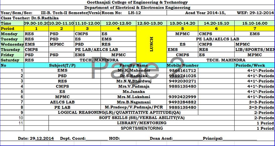
14 CLASS TIME TABLE
15 S. L no Unit No Topics to be covered Lecture schedule 1 1 Classification of measuring instruments-deflecting, controlling and damping systems, ammeters and voltmeters Total no of Periods Teaching aids 2 BB PMMC, MI and MC instruments 2 BB Expression for the deflecting torque and control 1 BB torque Errors and compensation and extension of range 1 BB using shunts and series resistance Electrostatic voltmeters-electrometer type and attracted disc type, Extension of range of electrostatic voltmeters 1 BB Tutorial-1 1 BB 2 2 Introduction to CT & PT- Design considerations 1 BB Ratio and phase angle errors 1 BB Types of P.F meters-dynamometer and moving iron 1 BB type, I ph and 3 ph meters 1 BB Frequency meters- resonance type and Weston type 1 BB Synchroscopes 1 BB Additional Topic-1 1 LCD Tutorial-2 1 BB Solve University Question Papers 1 BB Assignment Test-I Single phase dynamometer wattmeter-lpf & UPF 1 BB Double element and three element dynamometer 1 BB wattmeter Expression for deflecting and controlling torques 1 BB and extension of range of wattmeter using instrument transformers Measurement of active in balanced systems 1 BB Measurement of reactive powers in unbalanced 1 BB systems Tutorial-3 1 BB 4 4 Single phase induction type energy meter- driving 1 BB and braking torques Errors and compensation 1 BB Testing of energy meter by phantom loading using 1 BB RSS meter Three phase energy meter-tri-vector meter 1 BB Maximum demand meters. 1 BB
16 Additional Topic-2 1 LCD Tutorial-4 1 BB Solve University Question Papers 1 BB Assignment Test-II 1 Mid Test-I Principle and operation of D.C Crompton s 1 BB potentiometer Standardization 1 BB Measurement of unknown resistance, current, 1 BB voltage AC Potentiometers polar and coordinate type 1 BB Standardization- applications 1 BB Tutorial Method of measuring low, medium and high 1 BB resistances Sensitivity of wheatstone s bridge 1 BB Carey Foster bridge for measuring low resistance 1 BB Kelvin s double bridge for measuring low resistance 1 BB Measurement of high resistance- loss of charge 1 BB method Additional Topic-3 1 LCD Tutorial-6 1 BB Solve University Question Papers 1 BB Assignment Test-III Measurement of inductance and quality factor using 1 BB Maxwell s bridge and Hay s bridge Anderson s bridge, Owen s bridge 1 BB Measurement of capacitance and loss angle using 1 BB Desauty s bridge Wien s bridge 1 BB Schering bridge 1 BB Tutorial-7 1 BB 8 8 Ballistic galvanometer- equation of motion and flux 1 BB meter Constructional details and comparison of flux meter 2 BB with ballistic galvanometer Determination of B-H loop methods of reversals six 2 BB point method AC testing- iron loss of bar samples 2 BB
17 Core loss measurements by bridges and 2 BB potentiometers. Additional Topic-4 1 LCD Tutorial-8 1 BB Solve University Question Papers 1 BB Assignment Test-IV 1 Mid Test-II 1 Total No of classes required 69
18 1.6 Micro Plan:- SL. No Period No Unit No Date Topic to be covered in One lecture Reg/Additi onal ,30/12 Classification of measuring instrumentsdeflecting, controlling and damping systems, ammeters and voltmeters 31/12, 01/01 02/01 Expression for the deflecting torque and control torque 05/01 Errors and compensation and extension of range using shunts and series resistance 06/01 Electrostatic voltmeters-electrometer type and attracted disc type, Extension of range of electrostatic voltmeters Regular Teaching aids used LCD/OHP/ BB LCD/ BB PMMC, MI and MC instruments Regular LCD/ BB Regular Regular Regular LCD/ BB LCD/ BB LCD/ BB 07/01 Tutorial-1 BB ,09/01 Introduction to CT & PT- Design Regular LCD/ BB considerations, Ratio and phase angle errors 12/01 Types of P.F meters-dynamometer and moving Regular LCD/ BB iron type, 13/01 I ph and 3 ph meters Regular LCD/ BB 16/01 Frequency meters- resonance type and Weston Regular LCD/ BB type 19/01 Synchroscopes Regular LCD/ BB 20/01 SPEED DETECTION CAMERA Additional LCD/ BB 21/01 Tutorial-2 BB 22/01 Solve University Question Papers BB 23/01 Assignment Test-I /01 Single phase dynamometer wattmeter-lpf & UPF 28/01 Double element and three element dynamometer wattmeter 29/01 Expression for deflecting and controlling torques and extension of range of wattmeter Regular Regular Regular LCD/ BB LCD/ BB LCD/ BB Rema rks
19 using instrument transformers 30/01 Measurement of active in balanced systems Regular LCD/ BB 02/02 Measurement of reactive powers in unbalanced Regular LCD/ BB systems 03/02 Tutorial-3 BB /02 Single phase induction type energy meter- Regular LCD/ BB driving and braking torques 05/02 Errors and compensation Regular LCD/ BB 06/02 Testing of energy meter by phantom loading Regular LCD/ BB using RSS meter 09/02 Three phase energy meter-tri-vector meter Regular LCD/ BB 10/02 Maximum demand meters. Regular LCD/ BB 11/02 GYROSCOPE Additional LCD/ BB 12/02 Tutorial-4 BB 13/02 Solve University Question Papers BB 16/02 Assignment Test-II 18/02 Mid Test-I /02 Principle and operation of D.C Crompton s Regular LCD/ BB potentiometer 25/02 Standardization Regular LCD/ BB 26/02 Measurement of unknown resistance, current, Regular LCD/ BB voltage 27/02 AC Potentiometers polar and coordinate type Regular LCD/ BB 02/03 Standardization- applications Regular LCD/ BB 03/03 Tutorial /03 Method of measuring low, medium and high resistances Regular LCD/ BB 06/03 Sensitivity of wheat stone s bridge Regular LCD/ BB 09/03 Carey Foster bridge for measuring low Regular LCD/ BB resistance 10/03 Kelvin s double bridge for measuring low Regular LCD/ BB resistance 11/03 Measurement of high resistance- loss of charge Regular LCD/ BB method 12/03 Additional Topic-3 Additional LCD/ BB 13/03 Tutorial-6 BB 16/3 Solve University Question Papers BB 17/3 ELECTRONIC VOTING MACHINE , 19/3 Measurement of inductance and quality factor using Maxwell s bridge and Hay s bridge Regular LCD/ BB 20/3 Anderson s bridge, Owen s bridge Regular LCD/ BB 23/3 Measurement of capacitance and loss angle Regular LCD/ BB using Desauty s bridge 24/3 Wien s bridge Regular LCD/ BB 25/3 Schering bridge Regular LCD/ BB 26/3 Tutorial-7 BB /3 Ballistic galvanometer- equation of motion and flux meter Regular LCD/ BB
20 30,31/03 Constructional details and comparison of flux Regular LCD/ BB meter with ballistic galvanometer 01, 02/04 Determination of B-H loop methods of Regular LCD/ BB reversals six point method 06, 07/04 AC testing- iron loss of bar samples Regular LCD/ BB 08, 09/04 Core loss measurements by bridges and Regular LCD/ BB potentiometers. 10/04 MEMRISTOR Additional LCD/ BB 13/04 Tutorial-8 BB 15/04 Solve University Question Papers BB 16/04 Assignment Test-IV 17/04 Mid Test-II Total No of classes required 69 DETAILED NOTES
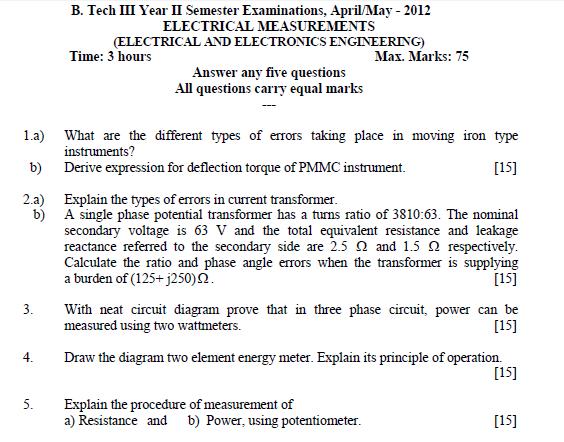
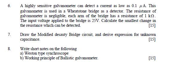
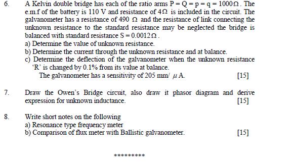
21 University Question papers of previous years
22
23
24
25
26
27
28
29 QUESTION BANK UNIT-1 1. Give the classification of measuring instruments and list the basic essential requirements? Discuss in detail about eddy current damping 2. Discuss in detail about PMMC derive the torque equation and list its merits and demerits? 3. Discuss in detail about MI instruments and derive the torque equation? 4. Explain the heterostatic connection of electrostatic voltmeter and derive an expression for torque. 5. Explain in detail about capacitance multiplier method in detail. UNIT-2 1. Derive an expression for actual ratio and phase angle for a potential transformer? 2. Give the remedies for reduction of errors in an instrument transformer? 3. Discuss in detail with neat diagram NALDAR-LIPMAN power factor meter? 4. Give the classification of frequency meters and discuss in detail about electrical resonance type frequency meter? 5. Explain about Weston frequency meter.
30 UNIT-3 1. List the errors in a wattmeter and discuss in detail about error produced due to pressure coil inductance. 2. Explain the necessity of LPF wattmeter and discuss about LPF wattmeter in detail. 3. State and prove BLONDEL s theorem. 4. Derive an expression for power factor (Ø) and reactive power using two wattmeter method? 5. Explain about three phase wattmeter? UNIT-4 1. Give the construction of energy meter and explain its principle of operation with neat diagram? 2. Derive the torque equation for a single phase energy meter? 3. List the errors in a energy meter? Discus in detail about lag adjustment? 4. What is creeping and discuss the compensation for creeping error? UNIT- 5 1a).Explain the operation of a basic dc slide wire potentiometer in detail. b). A basic slide wire potentiometer has a working battery voltage of 3v with negligible internal resistance. The resistance of slide wire is 400Ω and its length is 200cm. A 200 cm scale is placed along the slide wire. The slide wire has 1 mm scale divisions and is possible to read up to 1/5 th of a division. The instrument is standardized with 1.018v standard cell with sliding contact at cm mark on scale. Calculate: 1) working current 2) resistance of series rheostat 3) measurement range. 4) Resolution of the instrument. 2a). What is standardization and explain about Crompton s dc potentiometer. b). A single range potentiometer has 18 step dial switch where each step represents 0.1v. The dial resistors are 10Ω. The slide wire of potentiometer is circular and has 11 turns and resistance of 11 Ω. The slide wire has 100 divisions and interpolation can be done to to 1/4 th of division. The working battery has a voltage of 6v and negligible internal resistance.
31 Calculate.1) The measuring range of potentiometer 2) The resolution 3) Working current 4) Setting of the rheostat. 3a). Explain in detail about dry dale Tinsley potentiometer. b). Measurement for the determination of the impedance of a coli were made on a coordinate potentiometer are as follows. i) Voltage across 1 Ω standard resistance in series with the coil is (0.952-j0.34) Volts. ii) Voltage across a 10:1 potential divider connected to the terminals of the coil is (1.35+j1.28) volts. Calculate the resistance and reactance of the coil. 4a). Explain in detail about gal Tinsley potentiometer. b) Calculate the inductance of the coil from the following measurements on an ac potentiometer i) Voltage drop across a 0.1 Ω standard resistance connected in series with the coil =0.613< volts ii) Voltage across test coil through 100:1 voltage ratio box =0.781< volts Frequency is 50 Hz. 5a). Give the applications of ac potentiometers in detail. b) In the measurement of power by a polar potentiometer the following readings were obtained. i) Voltage across 0.2 Ω standard resistance in series with load =1.46<32 0 Volts. ii) Voltage across 200:1 potential divider across the line =1.37<56 0 Estimate the current, voltage, power and power factor of the load. UNIT-6 1 a) Discuss in detail about sensitivity of Wheatstone bridge. b) A Kelvin double bridge is balanced with the following constants: Outer ratio arm=100 Ω and 1000 Ω, Inner ratio arm= Ω and Ω, Resistance of the link=0.1 Ω, Standard resistance = Ω, Calculate the value of unknown resistance.
32 2a) Discuss the operation of Wheatstone bridge under small unbalance condition its limitations. b) A highly sensitive galvanometer can detect a current as low as 0.1nA. This galvanometer is used in Wheatstone bridge as a detector. The resistance of the galvanometer is negligible. Each arm of the bridge has a resistance of 1kΩ. The input voltage applied to the bridge is 20v. Calculate the smallest change in the resistance which can be detected. 3a) Discuss in detail about Carey foster slide Wire Bridge with necessary equations. b) In a Carey foster bridge a resistance of Ω is compared with a standard resistance of Ω, the slide wire has a resistance of Ω in 100 divisions. The ratio arms normally each of 10 Ω, are actually Ω and 9.95 Ω respectively. How far (in scale divisions) are the balance positions from those which would obtain of ration arms were true to their normal value? The slide wire is 100cm long. 4a) What are the practical difficulties for the measurement of high resistances. b) In a laboratory voltmeter of 200 Ω resistances and an ammeter of 0.02 Ω resistance are available. Calculate the value of resistance that can be measured by ammeter voltmeter method for which the two different circuit arrangements give equal errors. 5a) What are the various methods used for the measurement of high resistance and discuss in detail about loss of charge method. b) The length of the cable is tested for insulation by loss of charge method. An electrostatic voltmeter of infinite resistance is connected between the cable conductor and earth, forming there with a joint capacitance of 600pf. It is observed that after charging the voltage falls from 250v to 92 v in 1 minute. Calculate the insulation resistance of the cable. UNIT-7 1a) Explain in detail about Maxwell s inductance capacitance bridge with relevant derivations and list its advantages and disadvantages. b) The four arms of a-b-c-d has following impedances. Arm ab Z1=200<60 0 arm ad Z2=400<-60 0 Ω arm bc Z3=300<0 0 arm cd Z4=600<30 0 Determine whether it is possible to balance the bridge under above conditions.
33 2a) Explain in detail about Anderson s bridge with relevant derivations and list its advantages and disadvantages. b) The four arms of the bridge are as follows: Arm ab: an imperfect capacitor C1 with an equivalent series resistance of r1 Arm bc: a non-inductive resistance R3 Arm cd: a non-inductive resistance R4 Arm da: an imperfect capacitor C2 with an equivalent resistance of r2 in series with resistance R2. A supply at 450 hz is connected between terminals a and c the detector is connected between b and d. At the balance condition: R2=4.8 Ω, R3=200 Ω R4=2850 Ω and C2=0.5μf, r2=0.4 Ω Calculate values of C1 and r1 and also the dissipating factor for the capacitor. 3a) Explain in detail about Hay s bridge with relevant derivations and list its advantages and disadvantages b) The four arms of Hays Bridge are arranged as follows: AB: coil of unknown impedance. BC: non-reactive resistance of 100 Ω CD: non-reactive resistance of 833 Ω in series with 0.38 μf capacitor. DA: non-reactive resistor of Ω If the supply frequency is 50 Hz determine the resistance and inductance at the balance condition. 4a) Explain in detail about De sauty bridge with relevant derivations. b) In a heavy side Campbell bridge used for the measurement of a self inductance Lx with the equal ratio ier3=r4, the following results were obtained. With switch open M-15.8mH, r=25.7 Ω with switch closed M=0.2mH and r= 1.2 Ω. Find the resistance and self inductance of the coil. 5a) Explain in detail about Owens bridge with relevant derivations and list its advantages and disadvantages
34 b) An ac bridge circuit is used to measure the properties of sample sheet steel at 2 khz. At balance arm ab is test specimen. Arm bc is 100 Ω. Arm cd is 0.1μf capacitor and branch da is 834 Ω is series with 0.124μf capacitor. Calculate the effective impedance of the specimen under test conditions. UNIT-8: 1. Explain in detail about ballistic galvanometer with a neat diagram. 2. Explain in detail about fluxmeter with a neat diagram. 3. Derive an equation for motion. 4. Give the comparison between fluxmeter and ballistic galvanometer. Assignment Questions UNIT-1 1. Give the classification of measuring instruments and list the basic essential requirements? Discuss in detail about eddy current damping 2. Discuss in detail about PMMC derive the torque equation and list its merits and demerits? 3. Discuss in detail about MI instruments and derive the torque equation? 4. Explain the heterostatic connection of electrostatic voltmeter and derive an expression for torque. 5. Explain in detail about capacitance multiplier method in detail.
35 UNIT-2 1. Derive an expression for actual ratio and phase angle for a potential transformer? 2. Give the remedies for reduction of errors in an instrument transformer? 3. Discuss in detail with neat diagram NALDAR-LIPMAN power factor meter? 4. Give the classification of frequency meters and discuss in detail about electrical resonance type frequency meter? 5. Explain about Weston frequency meter. UNIT-3 1. List the errors in a wattmeter and discuss in detail about error produced due to pressure coil inductance. 2. Explain the necessity of LPF wattmeter and discuss about LPF wattmeter in detail. 3. State and prove BLONDEL s theorem. 4. Derive an expression for power factor (Ø) and reactive power using two wattmeter method? 5. Explain about three phase wattmeter? UNIT-4 1. Give the construction of energy meter and explain its principle of operation with neat diagram? 2. Derive the torque equation for a single phase energy meter? 3. List the errors in a energy meter? Discus in detail about lag adjustment? 4. What is creeping and discuss the compensation for creeping error? UNIT- 5 1a).Explain the operation of a basic dc slide wire potentiometer in detail. b). A basic slide wire potentiometer has a working battery voltage of 3v with negligible internal resistance. The resistance of slide wire is 400Ω and its length is 200cm. A 200 cm scale is placed along the slide wire. The slide wire has 1 mm scale divisions and is possible to read up to 1/5 th of a division. The instrument is standardized with 1.018v standard cell with sliding contact at cm mark on scale. Calculate: 1) working current 2) resistance of series rheostat 3) measurement range. 4) Resolution of the instrument. 2a). What is standardization and explain about Crompton s dc potentiometer. b). A single range potentiometer has 18 step dial switch where each step represents 0.1v. The dial resistors are 10Ω. The slide wire of potentiometer is circular and has 11 turns and resistance of 11 Ω. The slide wire has 100 divisions and interpolation can be done to to 1/4 th of division. The working battery has a voltage of 6v and negligible internal resistance. Calculate.1) The measuring range of potentiometer 2) The resolution 3) Working current 4) Setting of the rheostat.
36 3a). Explain in detail about dry dale Tinsley potentiometer. b). Measurement for the determination of the impedance of a coli were made on a coordinate potentiometer are as follows. i) Voltage across 1 Ω standard resistance in series with the coil is (0.952-j0.34) Volts. ii) Voltage across a 10:1 potential divider connected to the terminals of the coil is (1.35+j1.28) volts. Calculate the resistance and reactance of the coil. 4a). Explain in detail about gal Tinsley potentiometer. b) Calculate the inductance of the coil from the following measurements on an ac potentiometer i) Voltage drop across a 0.1 Ω standard resistance connected in series with the coil =0.613< volts ii) Voltage across test coil through 100:1 voltage ratio box =0.781< volts Frequency is 50 Hz. 5a). Give the applications of ac potentiometers in detail. b) In the measurement of power by a polar potentiometer the following readings were obtained. i) Voltage across 0.2 Ω standard resistance in series with load =1.46<32 0 Volts. ii) Voltage across 200:1 potential divider across the line =1.37<56 0 Estimate the current, voltage, power and power factor of the load. UNIT-6 1 a) Discuss in detail about sensitivity of Wheatstone bridge. b) A Kelvin double bridge is balanced with the following constants: Outer ratio arm=100 Ω and 1000 Ω, Inner ratio arm= Ω and Ω, Resistance of the link=0.1 Ω, Standard resistance = Ω, Calculate the value of unknown resistance. 2a) Discuss the operation of Wheatstone bridge under small unbalance condition its limitations. b) A highly sensitive galvanometer can detect a current as low as 0.1nA. This galvanometer is used in Wheatstone bridge as a detector. The resistance of the galvanometer is negligible. Each arm of the bridge has a resistance of 1kΩ. The input voltage applied to the bridge is 20v. Calculate the smallest change in the resistance which can be detected. 3a) Discuss in detail about Carey foster slide Wire Bridge with necessary equations. b) In a Carey foster bridge a resistance of Ω is compared with a standard resistance of Ω, the slide wire has a resistance of Ω in 100 divisions. The ratio arms normally each of 10 Ω, are actually Ω and 9.95 Ω respectively. How far (in scale divisions) are the balance positions from those which would obtain of ration arms were true to their normal value? The slide wire is 100cm long. 4a) What are the practical difficulties for the measurement of high resistances. b) In a laboratory voltmeter of 200 Ω resistances and an ammeter of 0.02 Ω resistance are available. Calculate the value of resistance that can be measured by ammeter voltmeter method for which the two different circuit arrangements give equal errors. 5a) What are the various methods used for the measurement of high resistance and discuss in detail about loss of charge method.
37 b) The length of the cable is tested for insulation by loss of charge method. An electrostatic voltmeter of infinite resistance is connected between the cable conductor and earth, forming there with a joint capacitance of 600pf. It is observed that after charging the voltage falls from 250v to 92 v in 1 minute. Calculate the insulation resistance of the cable. UNIT-7 1a) Explain in detail about Maxwell s inductance capacitance bridge with relevant derivations and list its advantages and disadvantages. b) The four arms of a-b-c-d has following impedances. Arm ab Z1=200<60 0 arm ad Z2=400<-60 0 Ω arm bc Z3=300<0 0 arm cd Z4=600<30 0 Determine whether it is possible to balance the bridge under above conditions. 2a) Explain in detail about Anderson s bridge with relevant derivations and list its advantages and disadvantages. b) The four arms of the bridge are as follows: Arm ab: an imperfect capacitor C1 with an equivalent series resistance of r1 Arm bc: a non-inductive resistance R3 Arm cd: a non-inductive resistance R4 Arm da: an imperfect capacitor C2 with an equivalent resistance of r2 in series with resistance R2. A supply at 450 hz is connected between terminals a and c the detector is connected between b and d. At the balance condition: R2=4.8 Ω, R3=200 Ω R4=2850 Ω and C2=0.5μf, r2=0.4 Ω Calculate values of C1 and r1 and also the dissipating factor for the capacitor. 3a) Explain in detail about Hay s bridge with relevant derivations and list its advantages and disadvantages b) The four arms of Hays Bridge are arranged as follows: AB: coil of unknown impedance. BC: non-reactive resistance of 100 Ω CD: non-reactive resistance of 833 Ω in series with 0.38 μf capacitor. DA: non-reactive resistor of Ω If the supply frequency is 50 Hz determine the resistance and inductance at the balance condition. 4a) Explain in detail about De sauty bridge with relevant derivations. b) In a heavy side Campbell bridge used for the measurement of a self inductance Lx with the equal ratio ier3=r4, the following results were obtained. With switch open M-15.8mH, r=25.7 Ω with switch closed M=0.2mH and r= 1.2 Ω. Find the resistance and self inductance of the coil. 5a) Explain in detail about Owens bridge with relevant derivations and list its advantages and disadvantages b) An ac bridge circuit is used to measure the properties of sample sheet steel at 2 khz. At balance arm ab is test specimen. Arm bc is 100 Ω. Arm cd is 0.1μf capacitor and branch da is 834 Ω is series with 0.124μf capacitor. Calculate the effective impedance of the specimen under test conditions. UNIT-8: 1. Explain in detail about ballistic galvanometer with a neat diagram.
38 2. Explain in detail about fluxmeter with a neat diagram. 3. Derive an equation for motion. 4. Give the comparison between fluxmeter and ballistic galvanometer. Unit 1 UNIT WISE QUIZ QUESTIONS AND LONG QUESTIONS Multiple Choice Questions
39 1. In d Arsonal galvonometer, an iron core is usually used between the permanant magnet pole faces. This is used so that a) Flux density in the air gap becomes high thereby a large deflecting torque is produced. b) The effect of stray magnetic fields is reduced c) Moment of inertia of moving parts becomes smaller d) None of the above Ans : ( a ) 2. If the damping in a d Arsonval galvonometer is only due to electromagnetic effects, the resistance required for critical damping is: a) G 2 / CJ b) G / CJ c) G / 2 CJ d) G 2 / : CJ Ans : ( d ) 3. Ayrton shunt is used in d Arsonval Galvanometers so as to limit the current in the galvanometer coil to its maximum permissible value. The relative value of current through the galvonometer coil and the shunt. a) Depends upon the value of resistance of galvonometer coil only b) Depends upon the value of resistance of galvonometer coil and the shunt. c) Does not depends upon the value of resistance of galvanometer coil. d) Non of the above. Ans : ( C ) 4. Electronic type instruments are primarily used as a) Ammeter b) Waltmeter c) Voltmeter d) Ohm meter Ans : ( c ) 5. The range of the electronic voltmeter can be extended by using
40 a) A capacitor in series with the voltmeter whose capacitance is grater than the capacitance of the voltmeter b) A capacitor in series with the voltmeter whose capacitance is smaller than the capacitance of the voltmeter c) A resistor in series with the voltmeter d) An inductor in series with the voltmeter Ans : ( b ) 6. The high torque to weight ratio in an anolog indicationg instrument indicates a) High friction loss b) Low friction loss c) Nothing regards friction loss d) None of the above Ans : ( b ) 7. Which meter has the highest accuracy in the prescribed limit of frequency range: a) PMMC b) Moving iron c) Electrodynomometer d) Rectifier Ans : ( c ) 8.Which instrument is the cheapest disregarding the accuracy? a) PMMC b) Moving iron c) Electrodynomometer d) Rectifier Ans : ( b ) 9. Which instrument has the highest frequency range with accuracy with in reasonable limits? a) Moving iron b) Electrodynomometer
41 c) Thermocouple d) Rectifier Ans : ( c ) 10. Swamping resistance is connected a) In series with the shunt to reduce temperature error in shunted ammeter. b) In series with the ammeter to reduce errors on account of friction. c) In series with meter and have a high resistance of temperature co-efficient in order to reduce temperature errors in ammeters. d) In series with the meter and have a negligible resistance co-efficient in order to reduce temperature error in shunted ammeters. Ans : ( d ) 11. A quardrant type dectostatic instruments uses two types of connections (i) Heterostatic and (ii) Idiostatic. An external battery is used. a) For idiostatic connection b) For heterostatic connection c) For both idiostatic and heterostatic connections d) None of the above. Ans : ( b ) 12. Horizontally mounted moving iron instruments use. a) Eddy curent damping b) Electromagnetinc clamping c) Fluid friction damping d) Air friction damping Ans : ( d ) 13. The eddy current damping cannot be used in moving iron instruments due to: a) They have a strong operating magnetic feild b) They are not normally used in vertical position c) They need a large damping force which can only be provided by air friction.
42 d) They have a very weak operating magnetic feild and introduction of a permanant magnet required for eddy current damping would distort the operating magnetic field. Ans : ( d ) 14. An electrostatic voltmeter draws a small value of current on d.c a) Under steady state condition respective of the applied voltage b) When switched on irrespective of the applied voltage c) When measuring low voltages d) When measuring high voltages Ans : ( a ) 15. Why are multimeters provided with separate scale for low a.c voltages? a) To improve the readability of the scale b) To have high accuracy c) To take in to account the high value of resistance of rectifier at low voltages (and current ) and also the fact that at low voltages (an current) the value of rectifier resistance ifs not constant but varies considerably even for small change in voltages ( or Current) d) None of the above. Ans : ( c ) 16. A voltmeter has resistance of 2000 Ω. when it is connect accross a d.c circuit its power consumption is 2mw Suppose this voltmeter is replaced by a voltmeter of 4000 Ω resistance, the power consumption will be. a) 4mw b) I mw c) 2 mw d) None of the above Ans : ( b ) 17. A 1mA d Arsonval movement has a resistance of 100. It is to be converted to a 10 v voltmeter. The value of multipliers resistance is. a) 900 Ω b) 9999 Ω c) 9900 Ω
43 d) 990 Ω Ans : ( c ) 18. A d Arsonval movement is rated at 50µA. Its sesitivity is a) Ω /v b) Ω /v c) 200 Ω/v d) Cannot be determined Ans : ( a ) 19. In order that an electrodynamometer type of instrument exhibits a pure square law response, the meter range should be limited to : a) -45 to +45 about the position for zero mutual inductance between fixed and mousing coils. b) -45 to +45 about the position for maximum mutual inductance between fixed and moving coil c) to 22.5 about the position for zero inductance between fixed and moving coils d) -90 to 90 about the position for maximum mutual inductance between fixed and moving coils Ans : ( a ) 20. Moving iron type of instrument can be used as a) Standard instruments for calibration of other instruments b) Transfer type instrument c) Indicator type instrument as on pands d) All of the above Ans : ( c ) 21. Moving iron instruments when measuring voltages are currents a) Indicate the same values of the measurement for both ascending and descending values. b) Indicate higher value of measurement for both ascending values. c) Indicate higher value of measurement and for descending values d) None of the above Ans : ( c ) 22. An electrodynomometer type of instruments finds its major use as
44 a) Standard instruments only b) Transfer instruments only c) Both as standard and transfer instrument d) An indicator type of instrument Ans : ( b ) 23. The power consumption of PMMC instruments is typically about. a) 0.25 w to 2w b) 0.25 mw to 2 mw c) 25 µw to 200 µw d) None of the above Ans : ( c ) 24. The frequency range of moving iron instrument is a) Audio frequency band 20Hz to 20 KHz b) Very low frequency band 10Hz to 30 KHz c) Low frequency band 30Hz to 300 KHz d) Power frequency 0 to 125 Hz Ans : ( d ) 25. Spring controlled moving iron instruments exhibit a square law response resulting in non-linear scale, the shape of the scale can be made almost linear by. a) Reducing rate of change of inductance, L, with deflection, Ø, as constant. b) Keeping 1/Ø, dl/dø as constant c) Keeping 1/kØ as constant where k is the spring constant d) Keeping o, dl/dø as constant. Ans : ( d ) 26. A megger is used for measurement of a) Low valued resistance b) Medium value resistance c) High value resistance, particularly insulation resistance
45 d) All the above Ans : ( d ) 27. A make before break switch is provided to disconnect the battery when the meter is not in use is a) Both series and shunt type ohmmeters b) Only series type ohmmeters c) Only in shunt type ohmmeters d) None of the above Ans : ( c ) 28. A moving iron instrument can be used for current and voltage measurments. a) In a.c circuits only b) In d.c circuits only c) In both a.c and d.c circuits for any value of frequency ( in case of a.c circuits ) d) In both a.c and d.c circuits for any frequency upto about 125Hz ( in case of a.c circuits ) Ans : ( d ) 29. In spring control measuring instruments, the scale is a) Uniform b) Cramped at the lower end and expanded at the upper end c) Expanded at the lower end and cramped at the upper end d) Cramped both at the lower and upper ands. Ans : ( b) 30. The moving iron voltmeter indicates a) The same value of d.c and a.c voltages b) Lower values for a.c voltage than for corresponding d.c voltages c) Higher values for a.c voltage than for corresponding d.c voltages d) None of the above Ans : ( b ) 31. A moving iron voltmeter reacts low for a.c voltmeter than for corresponding values of d.c voltages. The meters can be made to read equally for both a.c and d.c voltages.
46 a) If the resistance of the multiplier is made very high b) If the induction of the coil is made small c) The resistance of the coil made very large. d) If the multiplier resistance is shunted by a capacitor of appropriate value to make the circuit non-inductive Ans : ( d ) Unit 2: 1. The ratio of transformation in the case of potential transformers. a) Increases with the incresase in power factor of secondary burden b) Remains constant irrespective of the power factor of secondary burden c) Decreases increase in power factor of secondary burden d) Non of the above. Ans ( C ) 2.In case of potential transformers a) The phase angle error is always positive b) The phase angle error is always negetive c) The phase angle error is usually zero. d) The phase angle error is always positive when the secondary winding voltage reversed leads the primary winding voltage and is negative when the secondary winding voltage reversed logs behind the primary winding voltage. Ans ( d ) 3.The disadvantages of using multipliers with voltmeters at high voltages are : a) The power consumption of multipliers becomes large at large voltages. b) The multipliers at high voltages have to be shieled in order to present capacitive currents. c) The metering circuit is not electrically isolated from the power circuit. d) All the above. Ans ( b )
47 4. The nominal ratio of current transformer is a) Primary windingcurrent / secondary winding current b) Rated Primary winding current / Rated secondary winding current c) Number of Primary winding turns / number of secondary winding turns d) All the above Ans ( b ) 5.The error in the current transformers can be reduced by designing them with a) High permeability and low loss core materials, avoiding any joints in the core and also keeping the flux density to a low value. b) Using primary and secondary winding as close to each other as possible c) Using a large cross section for both primary and secondary winding conductiors d) All the above Ans ( a ) 6. Capacitive potential tranformers are used a) For primary wing phase voltage above 100 KV b) For keeping the value of transformation ratio constant irrespective of the burden by making certain adjustment c) Because they are cheper than the electromagnetic transformers above a certain voltage range d) All the above Ans ( a ) 7. The size of potential transformers a) Is the same as power transformers of the same VA rating b) Is much greater than that of power transformers of the same VA ratings because they are designed for low ratio and phase angle errors which require large sized cores and winding conductors c) Is smaller than that of power transformers of the seme VA rating d) Non of the above Ans ( b ) 8. The transformation ratio in the case of a potential transformer is defined as ratio of
48 a) Primary winding voltage / secondary winding voltage b) Rated primary winding voltage / rated secondary winding voltage c) Number of turns of primary winding / number of turns of secondary windings d) All the above Ans ( a ) 9.The burden of current transformers is expressed in terms of a) Secondary winding current b) VA rating of transformers c) Voltage, current and power factor of secondary winding circuit d) None of the above. Ans ( b ) 10. The current in the primary winding of a current transformer depends upon a) Burden of the secondary winding of transformer b) Load connect to the system in which the C.T is installed c) Both burderns of the transformers secondary winding and load connected to the system d) Non of the above Ans ( b ) 11. Turns compensation is used in current transformers primarily for reduction of a) Phase angle error b) Both ratio and phase angle errors c) Rato error reduction in phase angle error is incidental d) Non of the above Ans ( b ) 12. The advantages of instruments transformers are: a) The readings of instruments used in conjuction with then do not depend upon their resistance, inductance etc.
49 b) The rating of instrument transformers have been standarized and the rating of instruments used in conjuction with them also get standardized. Therefore is reduction of cost and case in replacement c) The metering circuit is electrically isolated from the power circuit there by providing safly to operating personnel d) All the above Ans ( d ) 13. The disadvantages of shunts for use at high currents are : a) It is difficult to achieve good accuracy with shunts b) Power consumption of the shunts is large c) The metering circuit is not electrically isolated from the power circuit. d) All the above. Ans ( d ) 14. When the secondary winding of a current transformer is open circuited with the primary winding energized a) The whole of the primary current produces large value of flux in the core ( limited to only saturation ) there by producing a large voltage in the secondary winding. b) The large voltage may act as safety hezard for the operators and may even ruptured the insulation c) When the large magnetizing force is taken off its leaves a large value of residual magnetism d) All the above. Ans ( d ) 15. A short circuiting link is provided on the secondary side of a current transformer because. a) When the secondary winding of the CT is short circuited by the link with the primary winding energized and very high current of flows on the primary side. b) When the secondary winding of the CT is short circuited by the link with the primary winding energized, it is possible to make any adjustments in the secondary winding circuits like replacing a faculty ammeter. c) When sort circuiting link is opened with the secondary winding open circuited, the current on the primary side falls to almost zero. d) All the above.
50 Ans ( b ) 16. When the secondary winding of a potential transformer is suddenly open circuited with primary winding excited. a) Large voltages are produced in the secondary winding which may be a safety hazard to operating personal b) The large voltagees so produced may rupture the insulation. c) The primary winding draws only the no load current. d) Non of the above. Ans ( c ) 17. The ratio and phase angle errors in potential transformers may be reduced by. a) Increasing in the exciting current b) Increasing the resistance and leekage reactance in the transformer. c) Not employing turns compensation d) Non of the above. Ans ( d ) 18. R.C.F = a) Kact / Knom b) Knom / Kact c) Kt / Knom d) Knom / Kt Ans ( a ) methode is employed for the reduction of magneting and loss components of instrument transformers a) Using meterial of high permeability b) Keeping flux density in the core to low value c) Choosing low reactent score d) All the above. Ans ( d )
51 20. A Potential transformer is a transformer used along with a low range voltmeter for measuring a high voltage a) Step up transformer b) Step down transformer c) Auto transformer d) Two winding transformer Ans ( b ) 21. Rotating field type moving iron power factor meter is also called as. a) D arsonval galvanometer b) Naldar Lipman P.F meter c) Westing House P.F Meter d) Ferozlianemic P.F meter Ans ( c ) 22. Alternating field type M.I P.F meter is also called as a) D arsonval galvanometer b) Nelder lipman P.F meter c) Westing house P.F meter d) Ferodianemic P.F meter Ans ( b ) 23. Machanical Resistance type frequency meter is also called as a) Fero dianemic b) Naldor Lipmon c) P.H.H.C d) Vibrating read e) Ans ( d ) Unit-3
52 1. The power in a dc circuit is measured with the help of ammeter and a voltmeter. The voltmeter is connected on the load side. The power indicated by the product of readings of the two instruments (VI) is : a) The power consumed by the load b) The sum of the power consumed by the load and the voltmeter c) The sum of the power consumed by the load and the ammeter d) None of the above Ans:b 2. In an electrodynamometer type wattmeter: a) The current coil is made fixed b) The pressure coil is fixed c) Any of the two coils is fixed d) Both coils should be movable Ans:a 3. In electrodynamometer type wattmeters, current coils are designed for carrying heavy currents use stranded wire or laminated conductors: a) To reduce iron losses b) To reduce hysteresis losses c) To reduce eddy current and hysteresis losses d) All the above Ans: c 4. In a electrodynamometer type wattmeters, the inductance of the pressure coil circuit produces error: a) Which is constant irrespective of the power factor of the load b) Which is higher at low powe factors c) Which is lower at low power factors d) None of the above Ans: b
53 5. A capacitor is connected across a portion of resistance of the multiplier in order to make the pressure coil circuit non-inductive. The value of the resistance is r while the total resistance and inductances of pressure circuit are respectively R p and L. The value of capacitance C is : a) 0.41L/r 2 b) 0.41L/R 2 p c) L/R 2 p d) L/r 2 Ans: d 6. When measuring the power with an electrodynamometer type wattmeter in a circuit where the load current is small: a) The current coil should be connected on the load side b) The pressure coil should be connected on the load side c) It is immaterial whether current coil or pressure coil is connected on the load side d) None of the above Ans: a 7. When measuring power with an electrodynamometer watmeter in a circuit where the load voltage is large: a) The current coil is connected on the load side b) The pressure col is connected on the load side c) The pressure coil is connected on the supply side d) It is immaterial whether the pressure coil or current coil is on the load side Ans: b 8. When measuring the power with an electrodynamometer wattmeter in a circuit having a low power factor: a) The current coil should be connected to the load side b) The current coil should be connected to the supply side c) The pressure coil should be connected to the load side d) A compensated wattmeter with pressure coil connected on the load side should be used Ans: d
54 9. BLONDEL S Theorem signifies: a) Single wattmeter method b) Three wattmeter method c) Four wattmeter method d) No of wattmeters used for the measuement of power in a n-phase system Ans: d 10. Major diadvantage of single wattmeter mehod for star/delta connected load: a) Non-availability of neutral point for star connected load b) Insertion of current coil in one of the phases of the star connected load c) Both a and b d) None of the above Ans: c 11.Blondel s theorem is applicable to: a) 3 Ø and 3 wire system b) 3 Ø and 4 wire system c) 1 Ø and 2 wire system d) 2 Ø and 3 wire system Ans: b 12. Blondel s theorem is not applicable to: a) 3 Ø and 3 wire system b) 3 Ø and 4 wire system c) Both a and b d) None of the above Ans: a 13.If W 1 and W 2 are the two wattmeter readings obtained by two wattmeters method then power factor cosø is given by the formula: 3Tan -1 [ (W 1-W 2)/(W 1+W 2) 14. The power in a three phase four wire system can be measured by using : a) 2 wattmeters
55 b) 4 wattmeters c) 3 wattmeters d) 1 wattmeter Ans:c 15. the power in a 3 phase circuit is measured with the help of 2 wattmeters. The readings of one wattmeter is positive and that of the other is negative. The magnitude fo readings are different. It can be concluded that the power factor of the circuit is: a) unity b) Zero (lagging) c) 0.5(lagging) d) less than 0.5 (lagging) Ans:d Unit-4 MULTIPLE CHOICE QUESTIONS: 1. A merz- price maximum demand indicator indicates: a) Maximum demand b) Average maximum demand over a specified period of time c) Maximum energy consumption d) All the above Ans: b 2. Creeping in a single phase induction type energy meter may be due to: a) Over compensation for friction b) Over voltage c) Vibrations d) All the above.
56 Ans: d 3.VAh metering can be done by using a) A ball and disc friction gearing b) Trivector meter c) Bridge connected rectifier d) All the above Ans: d 4. In a single phase induction type energy meter, in order to obtain true value of energy, the shunt magnet flux should lag behind the applied voltage by: a) 90 0 b) 0 0 c) 45 0 d) None of the above Ans: a 5. In an induction type meter, maximum torque is obtained when the phase angle between the two fluxes is : a) 0 0 b) 45 0 c) 60 0 d) 90 0 Ans: d
57 6. In an induction type energy meter, maximum torque is obtained when the parameters of rotating disc are: a) R=0 b) X=0 c) R=X d) None of the above Ans:b 7. In a single phase induction type energy meter the lag adjustment is done : a) To make the curret coil flux to lag 90 0 behind the applied voltage. b) To make the pressure coil flux to lag 90 0 behind the applied voltage c) To bring the pressure coil flux in phase with the applied voltage d) None of the above. Ans: b 8. In a circuit of a single phase induction type energy meter the pressure coil lags the voltage by 88 0, the errors while measuring power in two circuits having power factors of unity and 0.5 lagging are respectively are: a) % + 6.1% b) % -6.1% c) %-6.1% d) -6.1%-6.1% Ans: c 9. The reason why the eddy current damping cannot be used in moving iron instrument is :
58 a) They have a strong operating magnetic field b) They are not normally used in vertical position c) They need a large damping force which can only be provided by air-friction damping d) They have very weak operating magnetic field and introduction of a permanent magnet required for eddy current damping would distort the operating magnetic field. Ans: d 10. Phantom loading for testing of energy meters is used : a) To isolate the current and potential circuits b) To reduce power loss during testing c) For meters have low power rating d) They test meters having a large current rating for which loads may not be available in the laboratory this also reduces power losses during testing. Ans: d 11. In a house hold single phase induction type energy wattmeter, the meter can be reversed by: a) Reversing the supply terminals b) Reversing the load terminals c) Opening the meter connections and reversing the connections of both current and potential coil circuits. d) None of the above Ans:c 12. The errors due to voltage variations are: a) Linear magnetic characteristics of the shunt magnet core b) Linear magnetic characteristics of the series magnet core
59 c) Self braking torque d) Driving torque. Ans: a and c 13.Compensation for variation in supply voltage is provided by: a) Saturable magnetic shunt b) Swamping resistors c) Series resistors d) Shunt resistors Ans:a 14. The phase error can be compensated by the means of a) Lag adjustment b) Lead adjustment c) Shuntresistor d) Adjustable copper bands Ans:b 15. To overcome creeping error: a) Three holes are drilled b) Four holes are drilled c) Two holes are drilled d) None of the above Ans:c
60 16. The braking torque is prportional to: a) Square of the speed b) Square if the load current c) Speed d) load current Ans:b 17. Energy in three phase four wire system can be meacured by: a) Two wattmeter method b) Three element wattmeter c) Three element energy meter d) Two element energy meter. Ans:c 18. Energy in three phase three wire system can be measured by: a) Two wattmeter method b) Three element wattmeter c) Three element enrgy meter d) Two element energy meter. Ans:d
61 19. A Trivector meter directly reads : a) KVA and KVAR b) KVA and KW c) KWHr and KVA d) All the above Ans:c 20. The main functioning of msgnetic shunt is : a) To aid series magnetic flux b) Nullify series magnetic flux c) Divert the series mgnetic flux d) None of the above. Ans:c Unit-5 MULTIPLE CHOICE QUESTIONS 1)Potentiometer is a a. device for measuring voltage while presenting a very high impedance to the voltage under test. b. device for measuring voltage while presenting a very low impedance to the voltage under test. c. Device for measuring current while presenting a very high impedance to the current under test. d. Device for measuring current while presenting a very low impedance to the current under test. ANS: a 2) Slide wires are made of manganin. This is because maganin has a. high stability b. low stability c. high temperature d. low resisitivity ANS: a
62 3) Potentiometer is a device used to measure a. known voltage by comparing unknown voltage b. unknown voltage by comparing known voltage c. unknown voltage d. flux ANS: b 4) A potentiometer is basically a a. deflection as well as null type instrument b. null type instrument c. deflection type instrument d. digital instrument ANS: a 5) For measurement of emf of a standard cell we use a. galvanometer b. electro-dynamic voltmeter c. potentiometer d. zener reference ANS: c 6) The potentiometer wire should be of a. high resisitivity and low temperature coefficient b. low resisitivity and high temperature coefficient c. high resisitivity and high temperature coefficient d. low resisitivity and low temperature coefficient ANS: a 7) After standardizing, the position of the rheostat, R in the battery circuit a. should not be changed b. should be changed c. kept in maximum position d. kept in minimum position ANS: a 8) Voltbox is basically a device used for a. extending the voltage range of the potenetiometer b. measuring the current c. measuring the voltage d. measuring the power ANS: a 9) The power drawn by a potentiometer from the source, whose voltage is under measurement, under null condition is a. ideally zero
63 b. small c. high d. very high ANS: a 10) The standardization of ac potentiometers is done by a. directly using ac standard voltage sources. b. using dc standard sources and transfer instruments. c. using dc standard sources and d Arsonval galvanometer d. using ac standard sources and transfer instruments. ANS: b 11) Different type of potentiometers are wire wound potentiometer carbon film potentiometer plastic film potentiometer 12) Standardization of potentiometer is done in order that, they becomes a. accurate and direct reading b. precise c. accurate d. accurate and precise. ANS: a 13) consider the following statements: DC potentiometers is the best means available for measurement of dc voltages because i) The precision in measurement is independent of the type of detector used ii) It is based on null balance technique iii) It is possible to standardize before a measurement is undertaken. iv) It is possible to measure dc voltages ranging in value from mv to hundreds of volts Of these statements a. 2 and 4 are correct b. 1 and 4 are correct c. 2 and 3 are correct d. 3 and 4 are correct ANS: a 14) A direct current can be measured by a. a D.C. potentiometer in conjunction with a standard resistance b. a D.C potentiometer directly c. a D.C potentiometer in conjunction with a Volt ratio box d. a D.C potentiometer in conjunction with a voltmeter ANS: a
64 15) Phase angle in polar type potentiometer is measured from the position of. phase shifter 16) The sensitivity of a potentiometer can be improved by a. reducing the current flowing through the potentiometer wire b. reducing the length of potentiometer wire c. increasing the length of potentiometer wire d. reducing the resistance of the rheostat connected in series with the battery ANS: c 17) How does D.C. potentiometer differ from A.C. potentiometer difference between working of the two instruments is that in D.C. potentiometer only the unknown emf is balanced against a known potential drop, where as in case of A.C. potentiometer these two voltages are balanced in magnitude as well as phase. 18) The potentiometer method of measurement of resistance is suitable for measurement of a. low resistances only b. high resistances only c. medium resistances only d. very low resistances only ANS: a 19) In coordinate type potentiometer, if and are the two measured values from the two potentiometers, then the phase angle of the unknown voltage is given by a. tan -1 (v 1/v 2) b. tan -1 (v 2/v 1) c. tan -1 (v 1) d. tan -1 (v 2) ANS: b 20) A phase shifting transformer is used in conjunction with a a. Drysdale potentiometer b. as coordinate potentiometer c. Crompton potentiometer d. simple Larsen potentiometer ANS: a 21) The most commonly used detector in ac potentiometer work is a. vibration galvanometer b. ballistic galvanometer c. ear phone d. D'Arsonval galvanometer ANS: a 22) A transfer instrument employed in the standardization of a polar type a.c potentiometer is a. a thermal instrument
65 b. an electrostatic instrument c. a dynamometer instrument d. a moving coil instrument ANS: a 23) In drysdale a.c potentiometor, the two phase supply for the stator is obtained from a single phase supply by employing a phase splitting device consisting of a a. capacitor and a resistor b. inductor and a capacitor c. resistor and a inductor d. inductance only ANS: a 24) For measuring an ac voltage by an ac potentiometer, it is desirable that the supply for the potentiometer is taken from a. a source other than the source of unknown voltage b. capacitor c. the same source as the unknown voltage d. a battery ANS: d 25) The stator of the phase shifting transformer for use in conjunction with an ac potentiometer usually has _ winding a. single phase b. two phase c. three phase d. six phase ANS: c 26) For standardization of Drysdale ac potentiometer the instrument used is a. thermo-couple instrument b. rectifier ammeter c. Precision type electro-dynamometer ammeter d. PMMC ammeter ANS: b 27) In a.c ammeter calibration, the current is given by a. (voltage drop across standard resistor) / (Resistance of the standard) b. (Resistance of the standard) / (voltage drop across standard resistor) c. voltage drop across standard resistor d. Resistance of the standard ANS: c 28) The method of calibration of a.c voltmeter is similar to that adopted for calibration of a. d.c ammeter with d.c potentiometer b. wattmeter with d.c potentiometer
66 c. d.c voltmeter with d.c potentiometer d. p.f meter with d.c poteniometer ANS: a 29) The main difference between a simple potentiometer and vernier potentiometer is a. uses two measuring dials b. uses three measuring dials c. uses four measuring dials d. uses no measuring dials ANS: c 30) The actual voltage measured using potentiometer is given by V act = (potentiometer reading)/(v.r.box ratio) 31) A.C potentiometers are broadly classified as polar type ac potentiometer and coordinate type potentiometer 32) In standardization of A.C. potentiometer, the D.C. standardization is done first by replacing vibration galvanometer by D Arsonval galavanometer 33) Applications of A.C. potentiometers are calibration of voltmeter calibration of ammeter testing of energy meter and wattmeter measurement of self reactance of coil 34) Potentiometer is a three terminal device 35) If a polar A.C. potentiometer is used, give the equations for self reactance of the coil X = Z sin(ø c-ø s) = (R sv c/v s) sin(ø c-ø s) 36) Continuously changing voltage can be measured by Brook s deflectional potentiometer 37) The voltage along the slide wire at any point is proportional to the length of the slide wire where the point is obtained by moving sliding contact along the wire to get null deflection in the galvanometer for any battery whose EMF is to be measured 38) In potentiometer with true zero the typical range of slide wire is from volts to volts 39) Suppose a length of resistive material (such as nichrome wire) had three points of electrical contact: one at each end (points 1 and 3), plus a movable metal "wiper" making contact at some point between the two ends (point 2):
67 Describe what happens to the amount of electrical resistance between the following points, as the wiper is moved toward the left end of the resistive element (toward point 1)? State your Answers in terms of increase," "decrease," or "remains the same," Between points 1 and 2, resistance... Between points 2 and 3, resistance... Between points 1 and 3, resistance... As the wiper moves to the left (toward point 1): Between points 1 and 2, resistance decreases Between points 2 and 3, resistance increases Between points 1 and 3, resistance remains the same Unit-6 MULTIPLE CHOICE QUESTIONS 1) Which instrument has the lowest resistance? a. Ammeter b. Voltmeter c. Frequency meter d. Megger Ans: a 2) Which bridge is used for the measurement of low resistance a. Kelvin b. Wheatstone c. Hay's d. Wagner ground bridge Ans: a 3) Which bridge is used for the measurement of medium resistance a. Wheat stone bridge b. Hay`s bridge c. Wagner ground bridge d. Anderson's bridge Ans: a 4) Medium resistances in the range from a. 1Ω to 0.1MΩ b. 1Ω to 0.5 MΩ c. 1Ω to 0.1kΩ d. 1.Ω to 0.01MΩ Ans: a 5) A Wheatstone bridge cannot be used for precision measurements because errors are introduced into an account of a. Stray losses
68 b. magnetic field c. Galvanometer d. Resistance of connecting leads Ans: d 6) The Wheatstone bridge is said to be balanced when the potential difference across the galvanometer is a. 1 volt b. 2 volts c. 0 volts d. 4 volts Ans: c 7) The sensitivity of a Wheatstone bridge depends upon a. connecting wires b. galvanometer current sensitivity c. parameters of the bridge d. contact resistances Ans: b 8) R 1 and R 4 are the opposite arms of a wheat stone bridge as the R 3 and R 2. The source voltage is applied across R 1 and R 3. Under balanced conditions which are of the following is true. a. R 1=(R 2R 3)/R 4 b. R 1=(R 3R 4)/R 2 c. R 1=(R 2R 4)/R 3 d. R 1=R 2+R 3+R 4 Ans: a 9) Carey Fosters bridge is used for determining the difference between a. the standard S and unknown resistance R b. ratio arms P and Q c. the resistance P and unknown resistance R d. the resistance Q and unknown resistance R Ans: a 10) In Carey Fosters bridge resistance P and Q are first adjusted so that the ratio P/Q is approximately equal to the ratio a. S/R b. Q/P c. R/S d. R Ans: c 11) Carey Fosters bridge is used to determine a. very low resistances b. low resistances c. medium resistances
69 d. high resistances Ans: b 12) In a Carey Fosters bridge supply voltage is a. fixed b. variable c. not required d. first variable and then fixed Ans: a 13) Carey Fosters bridge is a modification of a. Wheatstone bridge b. Kelvin s double bridge c. Andersons bridge d. Hays bridge Ans: a 14) Carey Fosters bridge method gives a direct comparison between S and R a. in terms of lengths only b. in terms of P and Q c. in terms of galvanometer reading d. in terms of contact resistance Ans: a 15) In Carey Fosters bridge a slide wire of length 'L' is included between a. ratio arms P and Q b. the resistance P and unknown resistance R c. the resistance Q and unknown resistance R d. unknown resistance R and the standard S Ans: d 16) In Carey Fosters bridge the sliding contact is being connected to the a. Galvanometer b. Unknown resistance R c. Standard resistance S d. ratio arm P Ans: a 17) Balancing of the Carey Fosters bridge is obtained by varying the a. Standard resistance S b. Sliding contact on the slide wire c. Ratio arm P d. Ratio arm Q Ans: b 18) A Kelvin's double bridge is best suited for the measurement of a. Capacitance b. Low resistance c. High resistance d. inductance Ans: b
70 19) The Kelvin bridge is a modification of the wheat stone bridge and provides greatly increased accuracy in the measurement of a. medium values b. high values c. low values d. very low values Ans: c 20) In measurement of low resistance by Kelvin's double bridge two sets of readings are taken. One with the current in one direction and the other with direction of current reversed. This is done to eliminate the effect of a. thermo-electric emf b. stray magnetic fields c. accuracy d. constant supply Ans: a 21) The measurement of resistance of earth connection is carried out by a. loss of charge method b. potential fall method c. ohmmeter d. volt ammeter method Ans: b 22) Megger is essentially a a. dynamometer b. series type ohm meter c. shunt type ohmmeter d. megohmmeter Ans: d 23) The effect of leakage paths on the measurement are usually removed by some form of a. guard circuit b. capacitors c. resistance d. Inductors Ans: a 24) The loss of charge method is used for a. High R b. Low R c. Low L d. High L Ans: a 25) Guard circuit is used in measurement of high resistance in order to a. eliminate the error owing to leakage current over insulation b. eliminate the capacitive effect c. guard the resistance against stray electrostatic field d. avoid damage caused by high voltage used in measurement Ans: a
71 Unit-7 1)The bridge circuits use the methods and operate on principle. Ans:- comparison measurement, null-indication 2) In a bridge circuit when no current flows through the null detector which is generally galvanometer,the bridge is said to be Ans:- Balanced 3) In an ac.bridge for high frequencies are used as a source. Ans:- oscillators 4) Electronic oscillators They are used as a source of supply universely because A) The output waveform is very close to sine wave. B) The output frequency is very stable C) The output power is sufficient to drive the bridge circuits. D) All the above Ans:- D 5) Which of the following detectors can be used effectively below 200Hz with greater sensitivity A) Headphones B) Vibration galvanometers c) Tuneable amplifier detectors D) Any of the above Ans:-B 6) Which of the following bridges is also called as Maxwells Wien bridge? A) Maxwells capacitance bridge B) Andersons bridge C) Maxwells inductance capacitance bridge D) Hays bridge Ans:- C 7) The advantage (s) of anderson bridge are A) can be used for accurate measurement of capacitance interms of inductance B) the bridge is easy to balance from convergence point of view compared to maxwells bridge in case of low values of Q C) other bridges require variable capacitor but a fixed capacitor can be used for Andersons bridge D) all the above Ans:-D
72 8) what is the main disadvantage of de sauty bridge A) it is suitable only for the capacitors with high dielectric losses B) when the capacitors are with dielectric losses, then it is highly impossible to achieve balance condition C) construction is very complicated D) all the above Ans:-B 9)Which of the following bridges can be used for high Q values A) Maxwells inductance bridge B) Wiens bridge C) Andersons bridge D) Heys bridge Ans:- D 10) Which of the following is used for measuring incremental inductance A) Hays bridge B) Andersons bridge C) Maxwells bridge D) Owens bridge Ans:- D 11) The detector used in high voltage Schering bridge is A) Headphones B) Vibration galvanometer C) Tuneable amplifier D) Any of the above Ans:- B 12) The bridge used for testing small capacitances at low voltages with very high precision and less losses is A) Schering bridge B) High voltage schering bridge C) De sauty bridge D) Modified De Sauty bridge Ans:- B 13) The advantage(s) of owens bridge is A) The balance equations are of simple form B) The balance equations are independent of the frequency C) It is possible to use this bridge over a wide range of inductances values D) All the above Ans:- D
73 14) A capacitance comparison bridge is used to measure the capacitive impedance at a frequency of 3kHz. The bridge constants at bridge balance are C3=10uF, R1=1.2kohms, R2=100kohms & R3=120kohms find the equivalent series circuit of the unknown impedance. (Rx,Cx ) A) 10Mohms,0.12uF B)12mohms,0.16uF C)14Mohms,0.14uF D)13Mohms,0.10uF Ans:- A 15) Lx value for Maxwell inductance bridge is A)R2R3C1 C)R1L2/R2 B)R3L3/R1 D)R3L2/R2 Ans:- B 16) Cx value for Schering bridge is A)R4C2/R3 C)R4C2/R2 B)R2C2/R4 D)R3C2/R4 Ans:-A 17)For a series combination of Rx & Cx,the angle between the voltage across the series combination and voltage across the capacitor Cx, is called Ans:- Loss angle 18)Lx value for hays bridge is A)R2R3C1 C)(R2/R3)C1 B)R1R3C1 D)(R1/R3)C1 Ans:- A 19) Lx value for inductance bridge is A)R2R3C1 C)(R3/R2)C1 B)R3R1C1 D)(R3/R1)C1 Ans:- A 20)In Maxwell inductance bridge Q= A)wR1C1 C)wR2/C3 B)wR2C3 D)wR1/C1
74 Ans:- A Unit-8 MAGNETIC MEASUREMENTS MULTIPLE CHOICE QUESTIONS 1. In case of ballistic galvanometer time period should be a. very large b. small c. medium d. large 2. Ballistic tests are used in magnetic measurements for determination of a. flux density B, magnetic force H and B-H curve and hysteresis loop of the specimen b. iron losses in the specimen c. B-H curve of the specimen d. Hysteresis loop of the specimen 3. The ballistic galvanometer is usually lightly damped so that a. it may oscillate b. it may remain stable c. amplitude of first swing is large d. amplitude of first swing is small 4. A Ballistic galvanometer is used to measure a. charge b. current c. voltage d. frequency 5. In a ballistic galvanometer, the inertia of the moving system is large so that a. it is accelerating fast as soon as the coil is energized b. it is practically stationary during the period the electricity is passing through the coil c. the amplitude of oscillations is small d. the frequency of oscillation is large 6. Ballistic galvanometer, can be calibrated by which of these one method? a. standard solenoid b. standard resistor c. Diode d. BJT
75 7. The construction of a ballistic galvanometer is similar to a a. MI meter b. vibration galvanometer c. PMMC meter d. D'Arsonval galvanometer 8. In magnetic measurements this galvanometer is usually connected across a a. search coil b. emf c. resistor d. inductor 9. Flux meter has a. high electro magnetic damping b. eddy current damping c. air friction damping d. fluid friction damping 10. An advantage of flux meter is a. The industrial form of flux meter is very large b. Its scale is calibrated in weber directly c. The deflection is dependent of the time taken by the flux change d. Its scale is calibrated in Weber-turns directly 11. Which of the following measures the magnetic flux density? a. Grassot flux meter b. Ballistic galvanometer c. Permeameter d. ammeter 12. A PMMC instrument can be used as a flux meter by a. removing the control springs b. using a low resistance shunt c. making the control springs of large moment of inertia d. using a high series resistance 13. The flux meter is a special type of ballistic galvanometer provided with a. large controlling torque damping ratio b. heavy electro-magnetic damping and large controlling torque c. small electro-magnetic damping and small controlling torque d. heavy electro-magnetic damping and very small controlling torque 14. Flux meter is _ a. portable b. not portable c. more sensitive d. not accurate 15. The flux meter is _ than ballistic galvanometer a. less sensitive
76 b. more sensitive c. not accurate d. not portable 16. The flux meter is accurate than the a. Ballistic galvanometer b. Vibration galvanometer c. D'Arsonval meter d. PMMC meter 17. _ factor is the ratio of the total flux to the useful flux. a. Leakage b. Form c. Utility d. Dispersion 18. B-H curve can be used for determination of a. eddy current losses b. iron losses c. Hysteresis losses d. stray losses 19. The method available for the determination of BH curve of a specimen is a. step by step method b. flux meter c. Ballistic galvanometer d. A.C. Potentiometer 20. In step by step method (BH curve determinations), the specimen must be _ before the test is started. a. demagnetized b. magnetized c. heated d. cool 21. In determination of BH curve,the magnetising winding is supplied from a _ supply in step by step method a. d.c b. a.c c. full rectified voltage d. half rectified voltage 22. In determination of BH curve by method of reversals, a _ specimen is first wound with a search coil. a. ring b. square c. rectangular d. triangular 23. In determination of BH curve by method of reversals, after demagnetization the test is started by setting the magnetising current at its a. lowest test value
77 b. highest test value c. zero value d. infinite value 24. In a Lloyd Fisher square used for determination of iron loss in a specimen of iron laminations, the current coil of the wattmeter is connected in the primary winding circuit, while the pressure coil is connected in the secondary winding circuit. This is done so that a. the I2R losses in the current coil are not included in wattmeter reading b. the I2R losses in the pressure coil circuit are not included in the wattmeter reading c. the I2R losses both in current coil and pressure coil circuit are not included in the wattmeter reading d. the wattmeter reads only the iron losses in the specimen of laminations 25. The method for iron loss measurement is a. Ammeter method b.wattmeter method c. Voltmeter method d. energy meter method 26. In an Epstein square, used for finding the iron loss in a stack of laminations, the laminations are so arranged that a. plane of each lamination is parallel to the plane of the square b. plane of each lamination is perpendicular to the plane of the square c. the plane of laminations may be either parallel or perpendicular to the plane of the square d. the plane of laminations may be at any angle to the plane of square 27. Lloyd Fisher magnetic square method, the bundles of strips are placed inside four similar magnetising coils of heavy wire, connected in _ to form the primary winding. a. series b. parallel c. cascade d. series-parallel 28. Electrical energy is consumed in alternating current circuits, due to presence of iron, in the form of _ a. iron losses b. copper losses c. stray losses d. rotational losses 29. The strips in L loyd Fisher magnetic square method are built up into a. one bundles b. three bundles c. two bundles d. four bundles 30. Lloyd Fisher magnetic square method, strips used are usually a. 25 cm long and 5 to 6 cm wide b. 100 cm long and 25 to 50 cm wide c. 1 cm long and 1 to 2 cm wide d. 100 cm long and 100 to 200 cm wide 31. In the measurement of iron loss by a.c bridge, the test is to be carried out at
78 a. Nyquist frequency b. radio frequencies c. resonant frequency d. audio frequencies 32. The a.c bridge network, can be used for the measurement of iron loss. a. Maxwell bridge b. Andersons bridge c. Hays bridge d. Owens bridge 33. The type of potentiometer which is used to measure iron loss is a. Gall-Tinsley b. rectangular type c. cromptons d. slide wire 34. Campbell bridge is used to measure a. Iron losses b. stray losses c. copper losses d. rotational losses 35. In A.C. Potentiometer method for the measurement of iron loss, a variable resistor and a standard resistor are connected in series with a. primary winding b. secondary winding c. Tertiary winding d. Three phase winding 36. Maxwell s bridge is applied to a. Iron loss and permeability measurements b. Copper loss c. Stray loss d. Rotational loss 37. In measurement of iron loss by a.c potentiometer method, the ring specimen carries a. two windings b. one winding c. three windings d. four windings 38. Iron losses in a specimen of iron are determined by using a co-ordinate type of potentiometer The loss component of no load current is read by a. Inphase potentiometer b. Quadrature potentiometer c. polyphase potentiometer d. d.c potentiometer

79 Tutorial Problems Unit-1
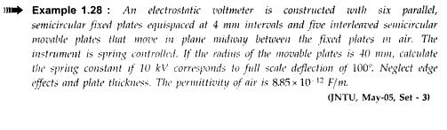

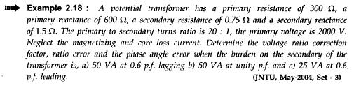
80 Unit-2

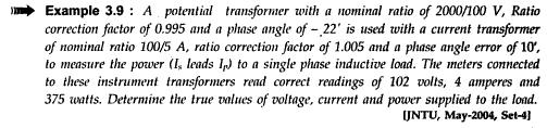
81 Unit-3

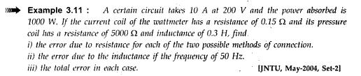
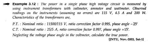
82 Unit-4
83 Unit-5
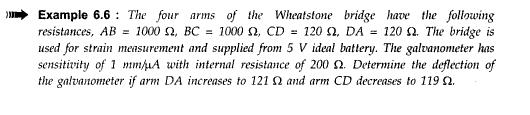
84 Unit-6
85 Unit-7
86

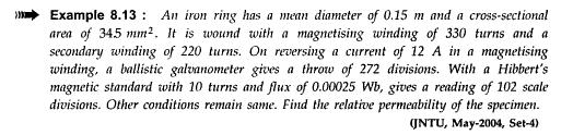
87 Unit-8
Bhoj Reddy Engineering College for Women, Hyderabad Department of Electronics and Communication Engineering Electrical and Electronics Instrumentation
 Bhoj Reddy Engineering College for Women, Hyderabad Department of Electronics and Communication Engineering Electrical and Electronics Instrumentation Academic Year: 2016-17 III B Tech II Semester Branch:
ELECTRICAL MEASUREMENTS
 R10 Set No: 1 1. a) Derive the expression for torque equation for a moving iron attraction type instrument and comment up on the nature of scale [8] b) Define the terms current sensitivity, voltage sensitivity
KKR & KSR INSTITUTE OF TECHNOLOGY & SCIENCES. Handouts
 KKR & KSR INSTITUTE OF TECHNOLOGY & SCIENCES (Approved by AICTE, New Delhi, Affiliated to JNTU Kakinada, Accredited by NAAC with A Grade) DEPARTMENT OF ELECTRICAL AND ELECTRONICS ENGINEERING Handouts Subject:
Code No: RR Set No. 1
 Code No: RR310202 Set No. 1 III B.Tech I Semester Regular Examinations, November 2006 ELECTRICAL MEASUREMENTS (Electrical & Electronic Engineering) Time: 3 hours Max Marks: 80 Answer any FIVE Questions
SIDDHARTH GROUP OF INSTITUTIONS :: PUTTUR (AUTONOMOUS) Siddharth Nagar, Narayanavanam Road QUESTION BANK (DESCRIPTIVE)
 Siddharth Nagar, Narayanavanam Road QUESTION BANK (DESCRIPTIVE)") SIDDHARTH GROUP OF INSTITUTIONS :: PUTTUR (AUTONOMOUS) Siddharth Nagar, Narayanavanam Road 517583 QUESTION BANK (DESCRIPTIVE) Suject : Electrical & Electronic Measurements(16EE224) Year & Sem: III-B.Tech
SIDDHARTH GROUP OF INSTITUTIONS :: PUTTUR (AUTONOMOUS) Siddharth Nagar, Narayanavanam Road 517583 QUESTION BANK (DESCRIPTIVE) Suject : Electrical & Electronic Measurements(16EE224) Year & Sem: III-B.Tech
PRINCIPLES OF MEASUREMENT AND INSTRUMENTATION & INSTRUMENTS
 Contents i SYLLABUS osmania university UNIT - I PRINCIPLES OF MEASUREMENT AND INSTRUMENTATION & INSTRUMENTS Principles of Measurement and Instrumentation and Instruments : Objectives of Measurements, Analog
INSTITUTE OF AERONAUTICAL ENGINEERING (Autonomous)
") INSTITUTE OF AERONAUTICAL ENGINEERING (Autonomous) Dundigal, Hyderabad - 500 04 ELECTRICAL AND ELECTRONICS ENGINEERING COURSE DESCRIPTION FORM Course Title Course Code Regulation Course Structure Course
INSTITUTE OF AERONAUTICAL ENGINEERING (Autonomous) Dundigal, Hyderabad - 500 04 ELECTRICAL AND ELECTRONICS ENGINEERING COURSE DESCRIPTION FORM Course Title Course Code Regulation Course Structure Course
 EI6301 - ELECTRICAL MEASUREMENTS UNIT I MEASUREMENT OF VOLTAGE AND CURRENT PART-A 1. A PMMC instrument has a 0.12T magnetic flux density in its air gaps. The coil dimensions are D = 1.5 cm and l =2.25
SAMPLE OF THE STUDY MATERIAL PART OF CHAPTER 2 Measurements of Basic Electrical Quantities 1 (Current Voltage, Resistance)
") SAMPLE OF THE STUDY MATERIAL PART OF CHAPTER 2 Measurements of Basic Electrical Quantities 1 (Current Voltage, Resistance) 2.1 Indicating Instruments Analog Instruments: An analog device is one in which
SAMPLE OF THE STUDY MATERIAL PART OF CHAPTER 2 Measurements of Basic Electrical Quantities 1 (Current Voltage, Resistance) 2.1 Indicating Instruments Analog Instruments: An analog device is one in which
INSTITUTE OF AERONAUTICAL ENGINEERING (Autonomous) Dundigal, Hyderabad ELECTRICAL AND ELECTRONICS ENGINEERING
 Dundigal, Hyderabad ELECTRICAL AND ELECTRONICS ENGINEERING") INSTITUTE OF AERONAUTICAL ENGINEERING (Autonomous) Dundigal, Hyderabad - 500 043 ELECTRICAL AND ELECTRONICS ENGINEERING QUESTION BANK Course Name : Electrical and Electronics Instrumentation Course Code
INSTITUTE OF AERONAUTICAL ENGINEERING (Autonomous) Dundigal, Hyderabad - 500 043 ELECTRICAL AND ELECTRONICS ENGINEERING QUESTION BANK Course Name : Electrical and Electronics Instrumentation Course Code
Measurement of Resistance and Potentiometers
 Electrical Measurements International Program Department of Electrical Engineering UNIVERSITAS INDONESIA Measurement of Resistance and Potentiometers Jahroo Renardi Lecturer : Ir. Chairul Hudaya, ST, M.Eng.,
UNIT II MEASUREMENT OF POWER & ENERGY
 UNIT II MEASUREMENT OF POWER & ENERGY Dynamometer type wattmeter works on a very simple principle which is stated as "when any current carrying conductor is placed inside a magnetic field, it experiences
UNIT II MEASUREMENT OF POWER AND ENERGY PART-A
 UNIT II MEASUREMENT OF POWER AND ENERGY PART-A 1. A 3 500 V motor load has a pf of 0.4. Two wattmeters connected to measure the input. They show the input to be 30 kw. Find the reading of each instrument
Question Bank SENSORS AND INSTRUMENTATION [EE-305/405]
![Question Bank SENSORS AND INSTRUMENTATION [EE-305/405]](/thumbs/95/124646158.jpg "Question Bank SENSORS AND INSTRUMENTATION [EE-305/405]") UNIT-1 1. Discuss liquid in glass thermometers? 2. Write a short note on strain gauges. 3. Mention the various temperature scales and relation between them. 4. An experiment is conducted to calibrate a
UNIT-1 1. Discuss liquid in glass thermometers? 2. Write a short note on strain gauges. 3. Mention the various temperature scales and relation between them. 4. An experiment is conducted to calibrate a
Sine waves by far the most important form of alternating quantity important properties are shown below
 AC DC METERS 1 Sine waves by far the most important form of alternating quantity important properties are shown below 2 Average value of a sine wave average value over one (or more) cycles is clearly zero
COURSE PLAN
 COURSE PLAN 26-27 Staff Name: DR S.M.SHASHIDHAR Sem:III q Sec:A Course Name: ELECTRICAL AND ELECTRONIC MEASUREMENTS Lesson plan author name: DR S.M.SHASHIDHAR Course Code:15EE36 Checked by: Total Contact
Question Paper Code : B.E./B.Tech. DEGREE EXAMINATION, NOVEMBER/DECEMBER Third Semester. Electrical and Electronics Engineering
 Question Paper Code : 31391 B.E./B.Tech. DEGREE EXAMINATION, NOVEMBER/DECEMBER 2013. Third Semester Electrical and Electronics Engineering EE 2201/EE 33/EI 1202/10133 EE 302/080280016 MEASUREMENTS AND
Electronic Measurements & Instrumentation. 1. Draw the Maxwell s Bridge Circuit and derives the expression for the unknown element at balance?
 UNIT -6 1. Draw the Maxwell s Bridge Circuit and derives the expression for the unknown element at balance? Ans: Maxwell's bridge, shown in Fig. 1.1, measures an unknown inductance in of standard arm offers
Module 1. Introduction. Version 2 EE IIT, Kharagpur
 Module 1 Introduction Lesson 1 Introducing the Course on Basic Electrical Contents 1 Introducing the course (Lesson-1) 4 Introduction... 4 Module-1 Introduction... 4 Module-2 D.C. circuits.. 4 Module-3
INSTITUTE OF AERONAUTICAL ENGINEERING DUNDIGAL , HYDERABAD
 INSTITUTE OF AERONAUTICAL ENGINEERING DUNDIGAL-500043, HYDERABAD Department of Electrical and Electronics Enigineering HAND OUT OF ELECTRICAL MEASUREMENT Course code : 56009 Course title : Electrical measurements
Aligarh College of Engineering & Technology (College Code: 109) Affiliated to UPTU, Approved by AICTE Electrical Engg.
 Affiliated to UPTU, Approved by AICTE Electrical Engg.") Aligarh College of Engineering & Technology (College Code: 19) Electrical Engg. (EE-11/21) Unit-I DC Network Theory 1. Distinguish the following terms: (a) Active and passive elements (b) Linearity and
Aligarh College of Engineering & Technology (College Code: 19) Electrical Engg. (EE-11/21) Unit-I DC Network Theory 1. Distinguish the following terms: (a) Active and passive elements (b) Linearity and
MEASUREMENT IMPORTANT QUESTIONS FUTURE SECURE INSTITUTE
 05. (Electrical Instruments and Measurements) 1. (Introduction to Electrical Measuring Instruments) (LMRC 2015) 1. Hot wire ammeters are used for measuring: (a) Only a.c. (b) Only d.c (c) Neither a.c nor
L T P EE 441: Analog Electronics (EE/IE) (3 1 3) Theory Marks =100 Sessional Marks = 50 Laboratory Marks = 50 Time = 3 hours
 (3 1 3) Theory Marks =100 Sessional Marks = 50 Laboratory Marks = 50 Time = 3 hours") EE 441: Analog Electronics (EE/IE) (3 1 3) 1. Bond Model of silicon crystal: Intrinsic carrier concentration, Effect of doping on carrier concentration. Holes and electrons, Majority and Minority carriers,
EE 441: Analog Electronics (EE/IE) (3 1 3) 1. Bond Model of silicon crystal: Intrinsic carrier concentration, Effect of doping on carrier concentration. Holes and electrons, Majority and Minority carriers,
Table of Contents...2. About the Tutorial...6. Audience...6. Prerequisites...6. Copyright & Disclaimer EMI INTRODUCTION Voltmeter...
 1 Table of Contents Table of Contents...2 About the Tutorial...6 Audience...6 Prerequisites...6 Copyright & Disclaimer...6 1. EMI INTRODUCTION... 7 Voltmeter...7 Ammeter...8 Ohmmeter...8 Multimeter...9
INDEX IEC:
 60050-300 IEC:2001 173 INDEX A absolute absolute error... 311-01-05 (absolute) frequency deviation... 314-08-07 accessory accessory (of a measuring instrument)... 312-03-01 accessory of limited interchangeability...
Synchronous Machines Study Material
 Synchronous machines: The machines generating alternating emf from the mechanical input are called alternators or synchronous generators. They are also known as AC generators. All modern power stations
ELECTROMAGNETIC INDUCTION AND ALTERNATING CURRENT (Assignment)
") ELECTROMAGNETIC INDUCTION AND ALTERNATING CURRENT (Assignment) 1. In an A.C. circuit A ; the current leads the voltage by 30 0 and in circuit B, the current lags behind the voltage by 30 0. What is the
ELECTROMAGNETIC INDUCTION AND ALTERNATING CURRENT (Assignment) 1. In an A.C. circuit A ; the current leads the voltage by 30 0 and in circuit B, the current lags behind the voltage by 30 0. What is the
MEASUREMENT AND INSTRUMENTATION QUESTION BANK UNIT I INTRODUCTION. Part A
 MEASUREMENT AND INSTRUMENTATION QUESTION BANK UNIT I INTRODUCTION Part A 1. Define Standard deviation. 2. Why calibration of instrument is important? 3. What are the different calibration methodologies?
COMPARISION METHODS OF MEASUREMENTS
 UNIT 3 COMPARISION METHODS OF MEASUREMENTS OBJECTIVES: We shall learn D.C & A.C potentiometers, D.C & A.C bridges, Transformer ratio bridges, Self-balancing bridges.. History: Bridges are among the most
INSTITUTE OF AERONAUTICAL ENGINEERING (Autonomous) Dundigal, Hyderabad
 Dundigal, Hyderabad") I INSTITUTE OF AERONAUTICAL ENGINEERING (Autonomous) Dundigal, Hyderabad-500043 CIVIL ENGINEERING TUTORIAL QUESTION BANK Course Name : BASIC ELECTRICAL AND ELECTRONICS ENGINEERING Course Code : AEE018
I INSTITUTE OF AERONAUTICAL ENGINEERING (Autonomous) Dundigal, Hyderabad-500043 CIVIL ENGINEERING TUTORIAL QUESTION BANK Course Name : BASIC ELECTRICAL AND ELECTRONICS ENGINEERING Course Code : AEE018
Reg. No. : BASIC ELECTRICAL TECHNOLOGY (ELE 101)
") Department of Electrical and Electronics Engineering Reg. No. : MNIPL INSTITUTE OF TECHNOLOGY, MNIPL ( Constituent Institute of Manipal University, Manipal) FIRST SEMESTER B.E. DEGREE MKEUP EXMINTION (REVISED
Department of Electrical and Electronics Engineering Reg. No. : MNIPL INSTITUTE OF TECHNOLOGY, MNIPL ( Constituent Institute of Manipal University, Manipal) FIRST SEMESTER B.E. DEGREE MKEUP EXMINTION (REVISED
SHRI RAMSWAROOP MEMORIAL COLLEGE OF ENGG. & MANAGEMENT B.Tech. [SEM I (EE, EN, EC, CE)] QUIZ TEST-3 (Session: ) Time: 1 Hour ELECTRICAL ENGINEE
![SHRI RAMSWAROOP MEMORIAL COLLEGE OF ENGG. & MANAGEMENT B.Tech. [SEM I (EE, EN, EC, CE)] QUIZ TEST-3 (Session: ) Time: 1 Hour ELECTRICAL ENGINEE](/thumbs/94/118213481.jpg "SHRI RAMSWAROOP MEMORIAL COLLEGE OF ENGG. & MANAGEMENT B.Tech. [SEM I (EE, EN, EC, CE)] QUIZ TEST-3 (Session: ) Time: 1 Hour ELECTRICAL ENGINEE") SHRI RAMSWAROOP MEMORIAL COLLEGE OF ENGG. & MANAGEMENT B.Tech. [SEM I (EE, EN, EC, CE)] QUIZ TEST-3 (Session: 2014-15) Time: 1 Hour ELECTRICAL ENGINEERING Max. Marks: 30 (NEE-101) Roll No. Academic/26
SHRI RAMSWAROOP MEMORIAL COLLEGE OF ENGG. & MANAGEMENT B.Tech. [SEM I (EE, EN, EC, CE)] QUIZ TEST-3 (Session: 2014-15) Time: 1 Hour ELECTRICAL ENGINEERING Max. Marks: 30 (NEE-101) Roll No. Academic/26
ELECTRICAL TECHNOLOGY
 ELECTRICAL TECHNOLOGY Subject Code: (EC303ES) Regulations : R6 JNTUH Class :II Year B.Tech ECE I Semester Department of Electronics and communication Engineering BHARAT INSTITUTE OF ENGINEERING AND TECHNOLOGY
SRI SATYA SAI INSTITUTE OF SCIENCE AND TECHNOLOGY
 DEE- 301 [ELECTRICAL MACHINE -I] Energy Conversion Principle - Law of conservation of energy, electromechanical energy conversion, classification of machines. I D. C. Generator - Principle, construction,
DEPT: II EEE EE6404-MEASUREMENT & INSTRUMENTATION 2MARK: UNIT-1. An instrument is a device for determining the value or magnitude of a quantity.
 DEPT: II EEE 2MARK: UNIT-1 1. Define instrument. An instrument is a device for determining the value or magnitude of a quantity. 2. What are the types of instruments? a. Mechanical instrument b. Electrical
SIR C R REDDY COLLEGE OF ENGINEERING EEE Department, ELURU.
 EEE3110-ELECTRICAL MEASUREMENTS LAB III/IV EEE, I Semester SIR C R REDDY COLLEGE OF ENGINEERING EEE Department, ELURU. NAME:. REGD.NO: SECTION:..Academic Year:.. SIR.C.R.REDDY COLLEGE OF ENGINEERING
 VIDYARTHIPLUS - ANNA UNIVERSITY ONLINE STUDENTS COMMUNITY UNIT 1 DC MACHINES PART A 1. State Faraday s law of Electro magnetic induction and Lenz law. 2. Mention the following functions in DC Machine (i)
Chapter Moving Charges and Magnetism
 100 Chapter Moving Charges and Magnetism 1. The power factor of an AC circuit having resistance (R) and inductance (L) connected in series and an angular velocity ω is [2013] 2. [2002] zero RvB vbl/r vbl
Ballari Institute of Technology & Management Ballari Department of Electrical and Electronics Engineering. Vision & Mission of the Institute
 Ballari Institute of Technology & Management Ballari Department of Electrical and Electronics Engineering Vision & Mission of the Institute Vision We will be a top notch educational Institution that provides
Unit 3 Magnetism...21 Introduction The Natural Magnet Magnetic Polarities Magnetic Compass...21
 Chapter 1 Electrical Fundamentals Unit 1 Matter...3 Introduction...3 1.1 Matter...3 1.2 Atomic Theory...3 1.3 Law of Electrical Charges...4 1.4 Law of Atomic Charges...4 Negative Atomic Charge...4 Positive
MAHARASHTRA STATE BOARD OF TECHNICAL EDUCATION
 Subject Code: 17322 (EEM) Model Answers Page No: 1 of 16 Important Instructions to examiners: 1) The answers should be examined by key words and not as word-to-word as given in the model answer scheme.
EE Chapter 7 Measuring Instruments
 EE 2145230 Chapter 7 Measuring Instruments 7.1 Meter Movements The basic principle of many electric instruments is that of the galvanometer. This is a device which reacts to minute electromagnetic influences
a) b) c) d) 0.01.
 b) c) d) 0.01.") 1. A galvanometer is an electromechanical device, it concerts: a) Mechanical energy into electrical energy. b) Electrical energy into mechanical energy. c) Elastic energy into electrical energy. d) Electromagnetic
1. A galvanometer is an electromechanical device, it concerts: a) Mechanical energy into electrical energy. b) Electrical energy into mechanical energy. c) Elastic energy into electrical energy. d) Electromagnetic
Solution for Electrical and Electronic Measurements
 Q.1) Solution for Electrical and Electronic Measurements May 2016 Index a). 2 b). 2 c). 3-4 d). 5-6 e).. 6 Q.2) a). 7-11 b). 11-16 Q.3) a). 17-20 b). 21-22 Q.4) a). 23-25 b). 25-27 Q.5) a). N.A b). 28-31
SHRI RAMSWAROOP MEMORIAL COLLEGE OF ENGG. & MANAGEMENT
 SHRI RAMSWAROOP MEMORIAL COLLEGE OF ENGG. & MANAGEMENT B.Tech. [SEM I (CE,EC,EE,EN)] QUIZ TEST-3 (Session: 2012-13) Time: 1 Hour ELECTRICAL ENGINEERING Max. Marks: 30 (EEE-101) Roll No. Academic/26 Refer/WI/ACAD/18
Analog Multimeter. household devices.
 1 Analog Multimeter A multimeter or a multitester, a.k.a.vom (volt-ohmmilliammeter), is an electronic measuring instrument that combines several measurement functions in one unit. A typical multimeter
INSTITUTE OF AERONAUTICAL ENGINEERING Dundigal, Hyderabad
 Course Name Course Code Class Branch INSTITUTE OF AERONAUTICAL ENGINEERING Dundigal, Hyderabad -500 043 AERONAUTICAL ENGINEERING TUTORIAL QUESTION BANK : ELECTRICAL AND ELECTRONICS ENGINEERING : A40203
Preface...x Chapter 1 Electrical Fundamentals
 Preface...x Chapter 1 Electrical Fundamentals Unit 1 Matter...3 Introduction...3 1.1 Matter...3 1.2 Atomic Theory...3 1.3 Law of Electrical Charges...4 1.4 Law of Atomic Charges...5 Negative Atomic Charge...5
Kuestion Electrical and Electronic Measurements
 Kuestion Electrical and Electronic Measurements www.kreatryx.com Contents Manual for Kuestion... 2 Type : Error Analysis... 3 Type 2: Enhancement of Instrument Range... 5 Type 3:PMMC... 6 Type 4: Moving
VALLIAMMAI ENGINEERING COLLEGE
 VALLIAMMAI ENGINEERING COLLEGE SRM Nagar, Kattankulathur 603 203 DEPARTMENT OF ELECTRONICS AND INSTRUMENTATION ENGINEERING QUESTION BANK IV SEMESTER EI6402 ELECTRICAL MACHINES Regulation 2013 Academic
VALLIAMMAI ENGINEERING COLLEGE
 P a g e 2 Question Bank Programme Subject Semester / Branch : BE : EE6201-CIRCUIT THEORY : II/EEE,ECE &EIE UNIT-I PART-A 1. Define Ohm s Law (B.L.T- 1) 2. List and define Kirchoff s Laws for electric circuits.
Chapter 30 Inductance, Electromagnetic. Copyright 2009 Pearson Education, Inc.
 Chapter 30 Inductance, Electromagnetic Oscillations, and AC Circuits 30-7 AC Circuits with AC Source Resistors, capacitors, and inductors have different phase relationships between current and voltage
2015 ELECTRICAL SCIENCE
 Summer 2015 ELECTRICAL SCIENCE TIME: THREE HOURS Maximum Marks : 100 Answer five questions, taking ANY TWO from GROUP A, ANY TWO from GROUP B and from GROUP C. All parts of a question (a,b,etc) should
INSTITUTE OF AERONAUTICAL ENGINEERING (AUTONOMOUS)
") Name Code Class Branch INSTITUTE OF AERONAUTICAL ENGINEERING (AUTONOMOUS) Dundigal, Hyderabad -500 043 CIVIL ENGINEERING TUTORIAL QUESTION BANK : ELECTRICAL AND ELECTRONICS ENGINEERING : A30203 : II B.
Name Code Class Branch INSTITUTE OF AERONAUTICAL ENGINEERING (AUTONOMOUS) Dundigal, Hyderabad -500 043 CIVIL ENGINEERING TUTORIAL QUESTION BANK : ELECTRICAL AND ELECTRONICS ENGINEERING : A30203 : II B.
A Novel Technique for the Measurement of relative permeability of magnetic materials
 American International Journal of Research in Science, Technology, Engineering & Mathematics Available online at http://www.iasir.net ISSN (Print): 2328-3491, ISSN (Online): 2328-3580, ISSN (CD-ROM): 2328-3629
Downloaded from Downloaded from
 IV SEMESTER FINAL EXAMINATION- 2002 SUBJECT: BEG232EC, Instrumentation Candidates are required to give their answers in their own words as far as practicable. The figure in the margin indicates full marks.
DIPLOMA IN ELECTRICAL ENGINEERING (DELVI) Term-End Examination December, 2014
 Term-End Examination December, 2014") No. of Printed Pages : 6 BIEE-039 DIPLOMA IN ELECTRICAL ENGINEERING (DELVI) Term-End Examination December, 2014 BIEE-039 : ELECTRICAL MEASUREMENTS AND INSTRUMENTS Time : 2 hours Maximum Marks : 70 Note
No. of Printed Pages : 6 BIEE-039 DIPLOMA IN ELECTRICAL ENGINEERING (DELVI) Term-End Examination December, 2014 BIEE-039 : ELECTRICAL MEASUREMENTS AND INSTRUMENTS Time : 2 hours Maximum Marks : 70 Note
PART A. 1. List the types of DC Motors. Give any difference between them. BTL 1 Remembering
 UNIT I DC MACHINES Three phase circuits, a review. Construction of DC machines Theory of operation of DC generators Characteristics of DC generators Operating principle of DC motors Types of DC motors
Question Paper Profile
 I Scheme Question Paper Profile Program Name : Electrical Engineering Program Group Program Code : EE/EP/EU Semester : Third Course Title : Electrical Circuits Max. Marks : 70 Time: 3 Hrs. Instructions:
SRI SUKHMANI INSTITUTE OF ENGINEERING & TECHNOLOGY DERA BASSI DEPARTMENT: ELECTRONICS & COMM. LABORATORY MANUAL LAB: EMI SUBJECT CODE: SEMESTER: 4th
 SRI SUKHMANI INSTITUTE OF ENGINEERING & TECHNOLOGY DERA BASSI DEPARTMENT: ELECTRONICS & COMM. LABORATORY MANUAL LAB: EMI SUBJECT CODE: SEMESTER: 4th EXPERIMENT NO-1 Aim:- Low Resistance Using Kelvin Double
INSTITUTE OF AERONAUTICAL ENGINEERING (AUTONOMOUS) Dundigal, Hyderabad
 Dundigal, Hyderabad") INSTITUTE OF AERONAUTICAL ENGINEERING (AUTONOMOUS) Dundigal, Hyderabad - 500 043 CIVIL ENGINEERING ASSIGNMENT Name : Electrical and Electronics Engineering Code : A30203 Class : II B. Tech I Semester Branch
INSTITUTE OF AERONAUTICAL ENGINEERING (AUTONOMOUS) Dundigal, Hyderabad - 500 043 CIVIL ENGINEERING ASSIGNMENT Name : Electrical and Electronics Engineering Code : A30203 Class : II B. Tech I Semester Branch
XII PHYSICS INSTRUMENTS] CHAPTER NO. 15 [ELECTRICAL MEASURING MUHAMMAD AFFAN KHAN LECTURER PHYSICS, AKHSS, K
![XII PHYSICS INSTRUMENTS] CHAPTER NO. 15 [ELECTRICAL MEASURING MUHAMMAD AFFAN KHAN LECTURER PHYSICS, AKHSS, K](/thumbs/80/81415743.jpg "XII PHYSICS INSTRUMENTS] CHAPTER NO. 15 [ELECTRICAL MEASURING MUHAMMAD AFFAN KHAN LECTURER PHYSICS, AKHSS, K") XII PHYSICS MUHAMMAD AFFAN KHAN LECTURER PHYSICS, AKHSS, K affan_414@live.com https://promotephysics.wordpress.com [ELECTRICAL MEASURING INSTRUMENTS] CHAPTER NO. 15 MOVING COIL GALVANOMETER An electrical
XII PHYSICS MUHAMMAD AFFAN KHAN LECTURER PHYSICS, AKHSS, K affan_414@live.com https://promotephysics.wordpress.com [ELECTRICAL MEASURING INSTRUMENTS] CHAPTER NO. 15 MOVING COIL GALVANOMETER An electrical
QUESTION BANK ETE (17331) CM/IF. Chapter1: DC Circuits
 CM/IF. Chapter1: DC Circuits") QUESTION BANK ETE (17331) CM/IF Chapter1: DC Circuits Q1. State & explain Ohms law. Also explain concept of series & parallel circuit with the help of diagram. 3M Q2. Find the value of resistor in fig.
QUESTION BANK ETE (17331) CM/IF Chapter1: DC Circuits Q1. State & explain Ohms law. Also explain concept of series & parallel circuit with the help of diagram. 3M Q2. Find the value of resistor in fig.
Course Title : CONVENTIONAL ELECTRICAL POWER GENERATION Course Code : 1EE301
 GANPAT UNIVERSITY INSTITUTE OF TECHNOLOGY (DIPLOMA-DEGREE SIX YEAR DUAL DEGREE INTEGRATED COURSE) GANPAT UNIVERSITY, MEHSANA [ 4 0 2 5 ] COURSE CURRICULUM OF DIPLOMA PROGRAMME Course Title : CONVENTIONAL
Lecture 36 Measurements of High Voltages (cont) (Refer Slide Time: 00:14)
 (Refer Slide Time: 00:14)") Advances in UHV Transmission and Distribution Prof. B Subba Reddy Department of High Voltage Engg (Electrical Engineering) Indian Institute of Science, Bangalore Lecture 36 Measurements of High Voltages
Advances in UHV Transmission and Distribution Prof. B Subba Reddy Department of High Voltage Engg (Electrical Engineering) Indian Institute of Science, Bangalore Lecture 36 Measurements of High Voltages
Jawaharlal Nehru Engineering College, Aurangabad.
 Jawaharlal Nehru Engineering College, Aurangabad. Laboratory Manual ELECTRICAL MEASUREMENT & TEACHNIQUES [EMT] For Second Year (EEP) Students Manual made by- Prof. J.S.Solanke FORWARD It is my great pleasure
Inductance, capacitance and resistance
 Inductance, capacitance and resistance As previously discussed inductors and capacitors create loads on a circuit. This is called reactance. It varies depending on current and frequency. At no frequency,
IOCL Electrical Engineering Technical Paper
 IOCL Electrical Engineering Technical Paper 1. Which one of the following statements is NOT TRUE for a continuous time causal and stable LTI system? (A) All the poles of the system must lie on the left
KINGS COLLEGE OF ENGINEERING DEPARTMENT OF ELECTRICAL AND ELECTRONICS ENGINEERING QUESTION BANK UNIT I BASIC CIRCUITS ANALYSIS PART A (2-MARKS)
") KINGS COLLEGE OF ENGINEERING DEPARTMENT OF ELECTRICAL AND ELECTRONICS ENGINEERING QUESTION BANK YEAR / SEM : I / II SUBJECT CODE & NAME : EE 1151 CIRCUIT THEORY UNIT I BASIC CIRCUITS ANALYSIS PART A (2-MARKS)
KINGS COLLEGE OF ENGINEERING DEPARTMENT OF ELECTRICAL AND ELECTRONICS ENGINEERING QUESTION BANK YEAR / SEM : I / II SUBJECT CODE & NAME : EE 1151 CIRCUIT THEORY UNIT I BASIC CIRCUITS ANALYSIS PART A (2-MARKS)
ECE215 Lecture 7 Date:
 Lecture 7 Date: 29.08.2016 AC Circuits: Impedance and Admittance, Kirchoff s Laws, Phase Shifter, AC bridge Impedance and Admittance we know: we express Ohm s law in phasor form: where Z is a frequency-dependent
ECE 215 Lecture 8 Date:
 ECE 215 Lecture 8 Date: 28.08.2017 Phase Shifter, AC bridge AC Circuits: Steady State Analysis Phase Shifter the circuit current I leads the applied voltage by some phase angle θ, where 0 < θ < 90 ο depending
FMCET UNIT I - INTRODUCTION
 UNIT I - INTRODUCTION 1. Write the main static characteristics? (April/may 2008) The main static characteristics are: Accuracy Sensitivity Reproducibility Drift Static error Dead zone Resolution Precision
(Approved by AICTE & Affiliated to Calicut University) DEPARTMENT OF ELECTRICAL & ELECTRONICS ENGINEERING : ELECTRICAL MEASUREMENTS AND
 DEPARTMENT OF ELECTRICAL & ELECTRONICS ENGINEERING : ELECTRICAL MEASUREMENTS AND") (Approved by AICTE & Affiliated to Calicut University) DEPARTMENT OF ELECTRICAL & ELECTRONICS ENGINEERING ELECTRICAL MEASUREMENTS AND INSTRUMENTATION LAB CLASS SEMESTER SUBJECT CODE SUBJECT : II YEAR (EEE)
(Approved by AICTE & Affiliated to Calicut University) DEPARTMENT OF ELECTRICAL & ELECTRONICS ENGINEERING ELECTRICAL MEASUREMENTS AND INSTRUMENTATION LAB CLASS SEMESTER SUBJECT CODE SUBJECT : II YEAR (EEE)
ENGINEERING ACADEMY X V
 1. Two incandescent bulbs of rating 230, 100 W and 230, 500 W are connected in parallel across the mains. As a result, what will happen? a) 100 W bulb will glow brighter b) 500 W bulb will glow brighter
TITLE: Introduction to various Basic Instruments of Electrical Science
 EXPERIMENT NO : 1 TITLE: Introduction to various Basic Instruments of Electrical Science OBJECTIVE: Introduction to various Supply Systems, Ammeter, Voltmeter, Wattmeter, Energy meter, Tachometer, Rheostat,
Pre-Laboratory Assignment
 Measurement of Electrical Resistance and Ohm's Law PreLaboratory Assignment Read carefully the entire description of the laboratory and answer the following questions based upon the material contained
Experiment 45. Three-Phase Circuits. G 1. a. Using your Power Supply and AC Voltmeter connect the circuit shown OBJECTIVE
 Experiment 45 Three-Phase Circuits OBJECTIVE To study the relationship between voltage and current in three-phase circuits. To learn how to make delta and wye connections. To calculate the power in three-phase
1. A battery has an emf of 12.9 volts and supplies a current of 3.5 A. What is the resistance of the circuit?
 1. A battery has an emf of 12.9 volts and supplies a current of 3.5 A. What is the resistance of the circuit? (a) 3.5 Ω (b) 16.4 Ω (c) 3.69 Ω (d) 45.15 Ω 2. Sign convention used for potential is: (a) Rise
ROEVER ENGINEERING COLLEGE ELAMBALUR, PERAMBALUR DEPARTMENT OF ELECTRICAL & ELECTRONICS ENGINEERING
 ROEVER ENGINEERING COLLEGE ELAMBALUR, PERAMBALUR 621 212 DEPARTMENT OF ELECTRICAL & ELECTRONICS ENGINEERING EE1003 HIGH VOLTAGE ENGINEERING QUESTION BANK UNIT-I OVER VOLTAGES IN ELECTRICAL POWER SYSTEM
Fatima Michael college of Engineering and Technology
 Fatima Michael college of Engineering and Technology DEPARTMENT OF ELECTRICAL AND ELECTRONICS ENGINEERING EE2303 TRANSMISSION AND DISTRIBUTION SEM: V Question bank UNIT I INTRODUCTION 1. What is the electric
1. Explain in detail the constructional details and working of DC motor.
 DHANALAKSHMI SRINIVASAN INSTITUTE OF RESEARCH AND TECHNOLOGY, PERAMBALUR DEPT OF ECE EC6352-ELECTRICAL ENGINEERING AND INSTRUMENTATION UNIT 1 PART B 1. Explain in detail the constructional details and
Exercises of resistors 1. Calculate the resistance of a 10 m long Copper wire with diameter d = 1.0 mm.
 Exercises of resistors 1. Calculate the resistance of a 10 m long Copper wire with diameter d = 1.0 mm. 2. Calculate the resistances of following equipment: using 220V AC a) a 1000 W electric heater b)
DEPARTMENT OF ELECTRICAL ENGINEERING
 DEPARTMENT OF ELECTRICAL ENGINEERING LAB MANUAL SUBJECT: EMI B.TECH -3 RD SEM KCT COLLEGE OF ENGG & TECH FATEHGARH PUNJAB TECHNICAL UNIVERSITY Prepared by:- Er. Prince Munjal (AP) B.Tech (EE) M.Tech( EE)
ELECTRONICS AND ELECTRICITY
 INTRODUCTION ELECTRONICS ND ELECTRICITY The science of Electronics and Electricity makes a very important contribution to our everyday existence. Electricity is concerned with the generation, transmission
1. (a) Determine the value of Resistance R and current in each branch when the total current taken by the curcuit in figure 1a is 6 Amps.
 Determine the value of Resistance R and current in each branch when the total current taken by the curcuit in figure 1a is 6 Amps.") Code No: 07A3EC01 Set No. 1 II B.Tech I Semester Regular Examinations, November 2008 ELECTRICAL AND ELECTRONICS ENGINEERING ( Common to Civil Engineering, Mechanical Engineering, Mechatronics, Production
Code No: 07A3EC01 Set No. 1 II B.Tech I Semester Regular Examinations, November 2008 ELECTRICAL AND ELECTRONICS ENGINEERING ( Common to Civil Engineering, Mechanical Engineering, Mechatronics, Production
REQUIRED SKILLS AND KNOWLEDGE UEENEEE104A. Topic and Description NIDA Lesson CARD #
 REQUIRED SKILLS AND KNOWLEDGE UEENEEE104A KS01-EE104A Direct current circuits T1 Topic and Description NIDA Lesson CARD # Basic electrical concepts encompassing: electrotechnology industry static and current
EE6201 CIRCUIT THEORY QUESTION BANK PART A
 EE6201 CIRCUIT THEORY 1. State ohm s law. 2. State kirchoff s law. QUESTION BANK PART A 3. Which law is applicable for branch current method? 4. What is the matrix formation equation for mesh and nodal
MEASUREMENTS & INSTRUMENTATION ANALOG AND DIGITAL METERS
 MEASUREMENTS & INSTRUMENTATION ANALOG AND DIGITAL METERS ANALOG Metering devices Provides monotonous (continuous) movement. ELECTRICAL MEASURING INSTRUMENTS ANALOG METERS A d Arsonval galvanometer (Moving
Electromagnetic Oscillations and Currents. March 23, 2014 Chapter 30 1
 Electromagnetic Oscillations and Currents March 23, 2014 Chapter 30 1 Driven LC Circuit! The voltage V can be thought of as the projection of the vertical axis of the phasor V m representing the time-varying
DEPARTMENT OF ELECTRICAL AND ELECTRONICS ENGINEERING QUESTION BANK SUBJECT CODE & NAME : EE 1402 HIGH VOLTAGE ENGINEERING UNIT I
 DEPARTMENT OF ELECTRICAL AND ELECTRONICS ENGINEERING QUESTION BANK SUBJECT CODE & NAME : EE 1402 HIGH VOLTAGE ENGINEERING YEAR / SEM : IV / VII UNIT I OVER VOLTAGES IN ELECTRICAL POWER SYSTEMS 1. What
Electrical Engineering Fundamentals
 Electrical Engineering Fundamentals EE-238 Sheet 1 Series Circuits 1- For the circuits shown below, the total resistance is specified. Find the unknown resistance and the current for each circuit. 12.6
NODIA AND COMPANY. Model Test Paper - I GATE Electrical & Electronic Measurement. Copyright By Publishers
 No part of this publication may be reproduced or distributed in any form or any means, electronic, mechanical, photocopying, or otherwise without the prior permission of the author. Model Test Paper -
ELECTRICAL ENGINEERING LABORATORY MANUAL (NEE 151/251)
") ELECTRICAL ENGINEERING LABORATORY MANUAL (NEE 151/251) DEPARTMENTS OF ELECTRONICS & COMMUNICATION ENGINEERING/ ELECTRICAL ENGINEERING 27, Knowledge Park-III, Greater Noida, (U.P.) Phone: 0120-2323854-58
ELECTRICAL ENGINEERING LABORATORY MANUAL (NEE 151/251) DEPARTMENTS OF ELECTRONICS & COMMUNICATION ENGINEERING/ ELECTRICAL ENGINEERING 27, Knowledge Park-III, Greater Noida, (U.P.) Phone: 0120-2323854-58
Basic Electrical Engineering
 Basic Electrical Engineering S.N. Singh Basic Electrical Engineering S.N. Singh Professor Department of Electrical Engineering Indian Institute of Technology Kanpur PHI Learning Private Limited New Delhi-110001
1. If the flux associated with a coil varies at the rate of 1 weber/min,the induced emf is
 1. f the flux associated with a coil varies at the rate of 1 weber/min,the induced emf is 1 1. 1V 2. V 60 3. 60V 4. Zero 2. Lenz s law is the consequence of the law of conservation of 1. Charge 2. Mass
Physics for Scientists & Engineers 2 2 = 1 LC. Review ( ) Review (2) Review (3) e! Rt. cos "t + # ( ) q = q max. Spring Semester 2005 Lecture 30 U E
 Review (2) Review (3) e! Rt. cos t + # ( ) q = q max. Spring Semester 2005 Lecture 30 U E") Review hysics for Scientists & Engineers Spring Semester 005 Lecture 30! If we have a single loop RLC circuit, the charge in the circuit as a function of time is given by! Where q = q max e! Rt L cos "t
Review hysics for Scientists & Engineers Spring Semester 005 Lecture 30! If we have a single loop RLC circuit, the charge in the circuit as a function of time is given by! Where q = q max e! Rt L cos "t
CHAPTER 6: ALTERNATING CURRENT
 CHAPTER 6: ALTERNATING CURRENT PSPM II 2005/2006 NO. 12(C) 12. (c) An ac generator with rms voltage 240 V is connected to a RC circuit. The rms current in the circuit is 1.5 A and leads the voltage by
Downloaded From All JNTU World
 Code: 9A02403 GENERATION OF ELECTRIC POWER 1 Discuss the advantages and disadvantages of a nuclear plant as compared to other conventional power plants. 2 Explain about: (a) Solar distillation. (b) Solar
INSTITUTE OF AERONAUTICAL ENGINEERING (Autonomous) Dundigal, Hyderabad ELECTRICAL AND ELECTRONICS ENGINEERING
 Dundigal, Hyderabad ELECTRICAL AND ELECTRONICS ENGINEERING") Course Name Course Code Class Branch INSTITUTE OF AERONAUTICAL ENGINEERING (Autonomous) Dundigal, Hyderabad - 500 043 ELECTRICAL AND ELECTRONICS ENGINEERING QUESTION BANK : ELECRICAL MACHINES I : A40212
Course Name Course Code Class Branch INSTITUTE OF AERONAUTICAL ENGINEERING (Autonomous) Dundigal, Hyderabad - 500 043 ELECTRICAL AND ELECTRONICS ENGINEERING QUESTION BANK : ELECRICAL MACHINES I : A40212
NZQA registered unit standard version 3 Page 1 of 5. Demonstrate and apply fundamental knowledge of electrical circuit engineering principles
 Page 1 of 5 Title Demonstrate and apply fundamental knowledge of electrical circuit engineering principles Level 3 Credits 15 Purpose This unit standard covers general fundamental electrical circuit theory