Manuals. Basic Electrical Engineering BE-104
|
|
|
- Noah Blair
- 5 years ago
- Views:
Transcription


1 Manuals Basic Electrical Engineering BE-104
2 S.NO. EXPERIMENT NAME DATE 1 Measurement of power & power factor in a single phase AC circuit using three Ammeter Method 2 Measurement of active & reactive power in single phase AC circuit SIGNATURE & REMARKS 3 Measurement of impedance of R-L, R-C,R-L-C & study of resonance phenomena 4 Study of constructional feature s of a D.C. M/C. 5 Perform load test on a single phase transformer 6 Study of transformer name plate Rating & Determination of ratio 7 Open circuit & Short circuit test on 1- Transformer 8 Measurement of power in 3 phase A.C. circuit by two wattmeter method. 9 Study of three Point & Four point starter
3 Measurement Of Power & Power factor in a Single Phase AC Circuit using Three Ammeter Method
4 OBJECT:- To measure power factor in a single phase A.C. circuit using Three Ammeters. Voltmeter 0-300V, MI; ammeters 10A, 5A, 5A, MI; single phase inductive variable load, rheostat 100,5A; variac 230V, 10A. APPARATUS REQUIRED:- THEORY:- The circuit to be used for measurement of power in an A.C. circuit using three ammeter is shown in fig 1. We know in a D.C. circuit the power is given by the product of voltage and current, whereas,in A.C. circuit it is given by the product of voltage, current and power factor. For this reason, it is not possible to find power in an A.C. circuit simply from the readings of a voltmeter and ammeter. In A.C. circuits power is normally measured by wattmeter. However, this method demonstrates that the power in a single phase A.C. circuits can be measured by using three ammeters. From the circuits shown in fig 1.we can write. Power consumed by load =P =VI 3 cos (1.1) Where I 3 is current through load and V is the voltage across load. The phasor diagram of this circuit can be drawn by taking the supply voltage V as the reference phasor diagram is shown in fig.2
5 I 2 v I 3 I 1 From the phasor diagram we can write I 1 2 =I 2 2 +I I 2 I 3 Cos.. (1.2) Power factor, Cos = I 1 2 -I 2 2 -I 3 2 /2I 2 I 3.. (1.3) I 2 = V/R [R is a known resistance] (1.4) Now from eq. 1.1 I 3 Cos = P/V Put this value in eq. 1.2 I 1 2 = I 2 2 +I I 2 I 3 Cos I 1 2 = I 2 2 +I I 2 P/V 2I 2 P/V= I 1 2 -I 2 2 -I 3 2 or P= (I 1 2 -I 2 2 -I 3 2 )V/2I 2 From eq. (1.4) we put the value of I 2 So P = (I12-I22-I32) (V.R)/(2V) P = (I12-I22-I32) (R/2). Eqs.1.3 and 1.5 show that we can find the power and power factor in an a.c. circuits by using 3- single phase ammeters, instead of a wattmeter.
6 Record your observation as shown in table Table observation and calculations for 3-Ammeters method. S.No Observations Calculation V Volts I 1 Amp I 2 Amp I 3 Amp P Cos PROCEDURE:- The stepwise procedure for conducting this experiment is given below: 1. Make the connections as per the fig. 2. Keep the rheostat at its maximum value. 3. keep the variac at its mini9mum position 4. Switch on the supply. 5. Increase the voltage applied using variac slowly, so that the reading of voltmeter and ammeter, A1 are appreciable. 6. Decrease the resistance R (rheostat) so that ammeter A2 gives suitable reading. 7. Take down the readings of voltmeter and three ammeters. 8. Change the position of rheostat and repeat step 7 a number of times. OBSERVATION:- CALCULATION:- For each set of observation calculate the power consumed (Eq 1.5) and the power factor (Eq 1.3). Next take the average of all the set of calculation for cos i.e., power factor; and P i.e., power consumed in the load.
7 The power factor of the circuit and the power consumed in circuit should be recorded here. RESULT:- PRECAUTIONS:- Following precautions should be taken care of while performing this experiment. 1. All connections should be tight. 2. The zero setting of all the meters should be checked before connecting them in the circuit. 3. The current through ammeter should never be allowed to exceed the current rating of rheostat and load used.
8 Measurement Of Active & Reactive power in Single Phase AC circuit
9 Object:- Measurement of active and reactive power in single phase A.C. Circuit. S.No. Name of Quantity Specification Type equipments range 1. Wattmeter A,125V Dynamo 2. Ammeter Amp. A.C. 3. Voltmeter V A.C. 4. Rheostat ohms - 5. Inductance(choke) Auto-transformer V A.C. 7. Connecting wires Apparatus Required:- Theory:- Wattmeter has two coils, one is called current coil and other is pressure coil. The current coil carries the load current and pressure coil carries a current proportional to and in phase with supply voltage. The deflection of wattmeter depends upon the currents in the two coil and upon the P.F. of the circuit. In the wattmeter the current coil are arranged for different ratings i.e. 2.5,5 Amp.etc. and similarly voltage coils are rated for 125 V, 250V, 500Vetc. While doing the experiment the proper range should be selected according to the load voltage and current.
10 Factor. The reading should be multiplied by a factor called the Multiplying Multiplying factor of wattmeter = Current range * Voltage range Full scale reading of wattmeter Active power:- It is the power, which is actually dissipated in the circuit Resistance. P = I 2 R = VI COS watts Reactive Power:- It is the power developed in the inductive reactance of the circuit. Q = I 2 X L Circuit Diagram:-
11
12 From diagram:- It is clear Sin = X L /Z Or, ZSin =X L Q = I 2 X L = I*I*X L Q = I*I*ZSin Q = V*I*Sin Q= V*I*Sin Volt Ampere Reactive (VAR) Power Triangle:- VI COS VI SIN VI Impedance Triangle:- R X L Z Z = (R 2 ) + (X L 2 )
13 Procedure:- (1) Connect the circuit according to the circuit diagram. (2) For different value of supply voltage takes the various observations. (3) Take atleast 3 sets or reading. Observation Table:- Multiplying factor of wattmeter =... S. NO V I Wattmeter reading Actual power Wattmeter Reading*M.F. P.F.=Power/(V*I) Active Power P= V*I*Cos Reactive Power(Q)= V*I*Sin Calculation: - Report: - Precautions: - Following precautions should be taken care of while performing this experiment. 1. All connections should be tight. 2. The zero setting of all the meters should be checked before connecting them in the circuit. 3. The current through ammeter should never be allowed to exceed the current rating of rheostat and load used. 4. Do not increase the current beyond the rated value of wattmeter. 5. The wattmeter should be connected properly in the circuit.
14 Measurement Of Impedance of R-L, R-C,R-L-C & study of resonance phenomena
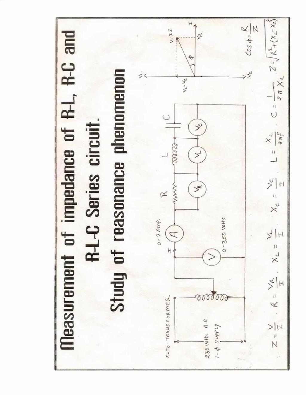
15 Object :- Measurement of impedance of R-L, R-C & R-L-C series circuit. Study of Resonance phenomenon. Apparatus Required :- S.no. Name of Equipment Quantity Range Type 1 Voltmeter V A.C. 2 Voltmeter V A.C. 3 Ammeter A A.C. 4 Resistance Inductance Capacitance Auto-Transformer V A.C. 8 Connecting Wires Theory :- (A) R-L Series Circuit :- It consists of a resistance of R -ohms & inductance of L- henry connected in series. In R-L Series circuit V s = R.M.S. Value of supply voltage V r = R.M.S. Value of resistance voltage drop = I R V L = R.M.S. Value of Inductance voltage drop = I X L I = R.M.S. Value of current Where, V r = I R and V L = I X L 2 2 V S = (V r + VL ) = (I R) 2 + (I X L ) 2 = I (R) 2 + (X L ) 2 I = V / R X L = V / Z Z = R 2 + X 2 L is the impedance of the circuit X L = 2 f L is the inductive reactance of the circuit L = X L / (2 f) X L = V L / I
16 (B) Series R C Circuit :- It consist of R Ohm and C Farads connected in series with source. V s = R.M.S. Value of supply voltage V r = R.M.S. Value of resistance voltage drop = I R V C = R.M.S. Value of capacitance voltage drop = I X C I = R.M.S. Value of current In R-C Series circuit V r = I R and V C = I X C 2 2 V S = (V r + VC ) = (I R) 2 + (I X C ) 2 = I (R) 2 + (X C ) 2 I = V / R X C = V / Z Where, Z = R 2 + X 2 C is the impedance of the circuit X C = 1 / 2 f C is the capacitance reactance of the circuit C = 1 / 2 f X C X C = V C / I (C) R-L-C Series circuit :- It consists Resistance of R ohms, Inductance of L- henry and Capacitance of C - Farads connected in series. V s = R.M.S. Value of supply voltage V r = R.M.S. Value of resistance voltage drop = I R V C = R.M.S. Value of capacitance voltage drop = I X C V L = R.M.S. Value of Inductance voltage drop = I X L I = R.M.S. Value of current
17 In R - L - C Series circuit V r = I R V C = I X C V L = I X L V S = V r 2 + (VL - V C ) 2 = (I R) 2 + (I X L - I X C ) 2 = I R 2 + (X L - X C ) 2 Where, Z = R 2 + (X L - X C ) 2 is the impedance of the circuit X L = 2 f L is the inductive reactance of the circuit L = X L / (2 f) X L = V L / I X C = 1 / 2 f C is the capacitance reactance of the circuit C = 1 / 2 f X C X C = V C / I V r = I R R = V r /I
18
19 Resonance: - Resonance in R-L-C series circuit: When capacitive reactance X C is equal to the inductive reactance X L then the circuit is said to be in resonance. The current will maximum, power factor is unity and lie in to phase with the supply voltage. - X C ) 2 V S = V r 2 + (VL - V C ) 2 = (I R) 2 + (I X L - I X C ) 2 = I R 2 + (X L At resonance, X L = X C Then I = V / R (Max) Now, X L = W C X C = 1 / W C W L = 1 / W C, 2 f L= 1/2 f C Fr = 1/2 L C Fr = Resonance Frequency Procedure :- (1) Connect the circuit diagram connecting R-L, R-C & R-L-C Series as shown in the circuit diagram. (2) The Auto-Transformer to zero position and switch on supply. (3) Adjust the Auto-Transformer till a suitable voltage is applied. (4) Take the reading from the voltage for V R,V L, V C & V S respectively. (5) Note the reading of ammeter. (6) Repeat step (3) Varying the supply voltage and record the reading in observation table.
20 Observation Table :- (A) For R-L Series Circuit :- S. No V r in Volt Voltmeter Reading V L in Volt V S in Volt Ammeter Reading (A) in Amp I Circuit Impedance Z = V / I Circuit Resistance R = V r / I Circuit Reactance X L = V L /I Circuit Inductance L = X L /2 f (B) For Series R C Circuit :- S. No V r in Volt Voltmeter Reading V C in Volt V S in Volt Ammeter Reading (A) in Amp I Circuit Impedance Z = V / I Circuit Resistance R = V r / I Circuit Reactance X C = V C /I Circuit Inductance C = 1/2 fx C (C)For R-L-C Series circuit :- S. No V r in Volt Voltmeter Reading V C in V L in Volt Volt V S in Volt Ammeter Reading (A) in Amp I Circuit Impedance Z = V / I Circuit Resistance R = V r / I Circuit Reactanc e X C = V C /I Circuit Reactance X L = V L /I
21 Calculation :-Calculation the various quantities as follows : (1) R = V r / I (2) X L = V L /I & L = X L / (2 f) (3) X C = V C /I & C = 1/ 2 f X C Result:- (1)Resistance (R) (2)Capacitance Reactance (3)Inductive Reactance (4)Inductor (L) (5)Capacitor (C) = = = = Henry = F Precaution :- (1) Make tight connection. (2) Do not touch any live wire. (3) Remove parallax error while taking reading from various instruments
22 Study of constructional features of a D.C. Machine
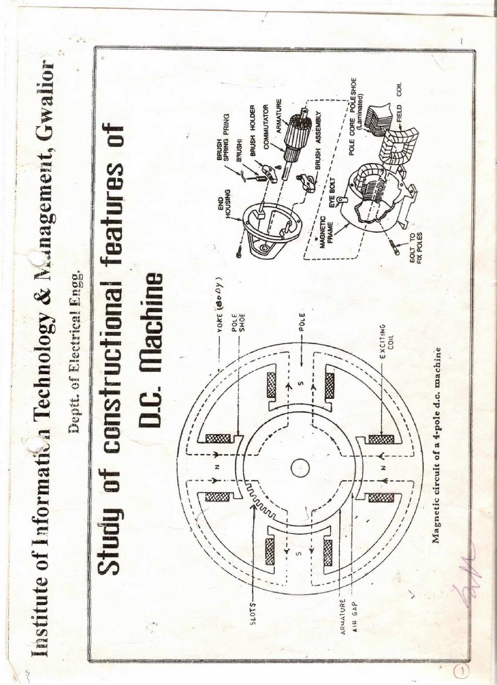
23 Object:- Study of constructional features of D.C. machines. D.C. Machines model. Apparatus Required:- Theory:- A d.c. machine is an Electro-Mechanical energy conversion device. It can convert mechanical power into d.c. electrical power and is known as a d.c. generator. On the other hand, when it converts d.c. electrical power into mechanical power it is known as d.c. motor. Contructional Details:- There are two main parts of a d.c. machine:- (A) Field System: - (i) Electromagnetic Poles (ii) Yoke (iii) Field Winding (B) Armature: - (i) Armature Core (ii) Armature Winding (iii) Commutator (1) Magnetic Frame or Yoke :- The outer cylindrical frame to which main poles and inter poles are fixed and by means of which the machine is fixed to the foundation is called the Yoke. It serves two purposes: (i) It provides mechanical protection to the inner parts of the
24 machine. (ii) It provides a low reluctance path for the magnetic flux. The yoke is made of cast iron for smaller machines and larger machines; it is made up of cast steel. (2) Pole core and Pole shoes:- The pole core and pole shoes are fixed to the magnetic frame or yoke by bolts. They serve the following purpose: (i) They support the field or exciting coils. (ii) They spread out the magnetic flux over the armature periphery more uniformly. (iii) Since pole shoes have large X-section, the reluctance of magnetic path is reduced. Usually, the pole core and pole shoes are made of thin cast steel. (3) Field or Exciting coils:- Anamelled copper wire is used for the construction of field or exciting coils. The coils are wound on the former and then placed around the pole core. When direct current is passed through the field winding, it magnetizes the poles which produce the require flux. The field coils of all the poles are connected in series in such a way that when current flows through them, the adjacent poles attain opposite polarity. (4) Armature core:- It is cylindrical in shape and keyed to the rotating shaft. At the outer periphery slots are cut, which accommodate the armature winding. The armature core serves the following purpose: (i) It houses the conductors in the slots.
25 (ii) It provides an easy path for magnetic flux. Since armature is a rotating part of the machine, reversal of flux takes place in the core, hence hysterisis losses are produced. To minimize these losses silicon steel material is used for its construction. The rotating armature cuts across the magnetic field which induces an e.m.f. in it. The e.m.f circulates eddy currents which results in eddy current losses in it. To reduce these losses armature core is laminated, in other word we can say that about 0.3 to 0.5 mm thick stampings are used for its construction. Each lamination or stamping is insulated from the outer by varnish layer. (5) Armature Winding:- The insulated conductors housed in the armature slots are suitably connected. This is known as armature winding. The armature winding is the heart of d.c. machine. It is a place where conversion of power takes place i.e. in case of generator, mechanical power is converted into electrical power and in case of motor, electrical power is converted into mechanical power. On the basis of connections, there are two types of armature winding names as:- (a) Lap Winding (b) Wave Winding. (5) Commutator:- It is the most important part of d.c. machine and serves the following purposes:- (i) It connects the rotating armature conductors to the stationary external circuit through brushes. (ii) It convert the alternating current induced in the armature conductor into unidirectional current in the external load circuit in generator action whereas, it converts the alternating torque into unidirectional torque produced in the armature motor action.
26 The commutator is of cylindrical shape and is made up of wedgeshaped hard drawn copper segments. The segments are insulated from each other by a thin sheet of mice. The segments are held together by means of 2 V-shaped rings that fit into the V-grooves cut into the segments. Each armature coil is connected to the commutator segment through riser. (6) Brushes:- The brushes are pressed upon the commutator and from the connecting link between the armature winding and the external circuit. They are usually made of high grade carbon because carbon is conducting material and the same time in powdered form provides lubricating effect on the commutator surface. The brushes are held in particular position around the commutator by brush holders. (7) End housings:- End housings are attached to the ends of the main frame and support bearings. The front housing supports the bearing and the brush assemblies whereas the rear housing usually supports the bearing only. (8) Bearings:- The ball or roller bearings are fitted in the end housings. The function of the bearings is to reduce friction between the rotating and stationary parts of the machine. Mostly high carbon steel is used for the construction of bearings as it is very hard material. (9) Shaft :- The shaft is made of mild steel with a maximum breaking strength. The shaft is used to transfer mechanical power from or to the machine. The rotating parts like armature core, commutator, cooling fan etc. are keyed to the shaft.
27
28 Perform load test On a single phase transformer
29 Object: - To perform load test on a single-phase transformer & to determine the following: (a)- Efficiency at different loads & to plot graph between efficiency Vs load currents. (b)- Regulation of the transformer & to plot graph between regulation Vs load currents. Apparatus Required:- S.No. Name of equipments Range Quantity Type 1. voltmeter 0-150V 1 A.C. 2. Ammeter 0-10 A 1 A.C. 3. Wattmeter 250V,2.5A 1 A.C. 4. Lamp bank load 250V,1Kw Transformer 230\115V Variac 0-260V 1 - Theory: - Wattmeter has two coils,one is called current coil & other is called as pressure coil. The current coil carries the load current & the pressure coil carries a current proportional to and in phase with supply voltage. The deflection of wattmeter depends upon the currents in the two coils and upon the P.F. of circuit. In the wattmeter the current coils are arranged for different ratings i.e. 2.5,5 Amp etc. and similarly voltage coils are rated for 125V, 250V, and 500V etc. While doing the experiment the proper range should be selected according to the load voltage & current.
30 The reading should be multiplied by a factor called the Multiplying factor. Multiplying factor of wattmeter = Current range * Voltage range Full scale reading of wattmeter Performance of the transformer can be determined as follows from the observation of load test- Efficiency of the transformer can be determined as ratio of the power output to the power input. Let power input to the transformer = W 1 Power output to the transformer = VI Thus the efficiency of particular load = VI\W 1 *100 % Efficiency of transformer will be maximum if Iron losses = Copper losses. Regulation of transformer determined as The change in secondary terminal voltage from no load to full load with respect to no load voltage is called voltage regulation of the transformer. Let E 2 = Secondary terminal voltage at no load (Bulb off) V 2 = Secondary terminal voltage at full load Then Voltage regulation = (E 2 -V 2 ) \ E 2 * 100

31 Circuit Diagram:-
32 Procedure:- 1. Connect the diagram as shown in fig. 2. Ensure that there is no load on the secondary winding of the transformer. 3. Switch on the A.C. supply & record no load voltage across the secondary winding. 4. Adjust approximately 10% of full load current in the secondary by switching on certain lamp bank load. Record the reading of the entire meter. 5. Reduce the load on the transformer by switching off the bulbs in the lamp bank load. 6. Switch off the A.C. supply. Observation table:- Multiplying factor: - S.No Input V 1 V 2 E 2 I 2 V 2 I 2 % %Regulation Load
33 Calculate the efficiency using the formula = (Output power \ Input power) *100 = (V 2 I 2 \W 1 )*100 % The Voltage Regulation %Voltage Regulation = (E 2 -V 2 )\E 2 *100 % The efficiency of the transformer on full load = The regulation of the transformer = Calculation:- Report:- Precaution:- 1)-Connection should be tight. 2)-Load on the transformer should nit increase beyond its capacity.
34 Study of transformer name plate Rating & Determination of ratio
35 OBECT: 1. Study & construction of single phase transformer. 2. Name plate rating of single phase transformer 3. Determination of transformation ration. APPARATUS REQUIRED: S.NO. Name of equipment Quantity Range Type Transformer 1 230/115V,1KVA Shell type 2. Auto Transformer ,10A Variac type 3. Voltmeter V Moving iron 4. Voltmeter V Moving iron THEORY: Study & construction of single phase transformer: The main elements of a transformer are two copper coils & laminated silicon steel core.a transformer is a static device or a machine that transforms electrical energy from one circuit to another electrical circuit through the medium magnetic flux. And without a change in frequency. The electrical circuit which receive energy from the supply mains is called primary winding and the other circuit which,which delivers electrical energy to the load,is called secondary winding.theoretically it may seem that transformers may be built to handle any voltage or current. But in reality there are limits to both the voltage & current. The name plate rating of a power transformer : The name plate rating of a power transformer usually contains Volt ampere rating of transformer in KVA. Voltage ratio or turn ratio in V 1 /V 2... Frequency of 1- or 3-. Equivalent impedance of a transformers in %.
36 A typical name plate of a 1- transformer is as follows: 230 Volts/115Volts, 50 Hz, 1KVA, Shell type,10 Amp. Here 1 KVA is the rated output at output terminals.230/115means when 230V. is the applied to the primary,the secondary voltage on full load at specified power factor is 115volts.The ratio of V 1 & V 2 is not exactly equal to N 1 /N 2, because of voltage drop in primary & secondary. Rated primary & secondary current can be calculated from the rated KVA and corresponding rated voltage thus Rated (Full load ) primary current = KVA /V 1 = 1000/230 = 4.35 Amps Rated (Full load ) secondary current = KVA /V 2 = 1000/115 = 4.35 Amps Rated frequency is the frequency for which the transformer is designed to operate. TRANSFORMATION RATIO: The turn ratio of the single phase transformer can be found by measuring the primary & secondary voltage. Let V 1 &V 2 is the primary and secondary voltage at on load. 1/K = V 1 / V 2 = N 1 /N 2 = I 2 /I 1 = Turn Ratio Induced E.M.F. in primary winding, E 1 =4.44f N 1 Volts Induced E.M.F. in secondary winding, E 2 =4.44f N 2 Volts For ideal transformer E 1 = V 1 and E 2 = V 2 Hence, Transformation Ratio K = V 2 / V 1 = N 2 / N 1 = I 1 / I 2 PROCEDURE: 1. Connect the circuit as per figure & set up auto transformer to zero position. 2. Switch on A.C. supply and adjust the Auto transformer till a suitable voltage. 3. Record voltage, V 1 across the primary and V 2 across the secondary winding. 4. Vary the Auto transformer and repeat above step,take at least 3 readings. 5. switch off the supply. OBSERVATION: S.NO. Primary Voltage V 1 Secondary Voltage V 2 K = V 2 / V
37 CIRCUIT DIAGRAM:
38 RESULT: The transformation ratio of given transformer is.. PRECAUTION: 1. Connection should be tight. 2. Do not touch on live wire. 3. Load on the transfer should not increase beyond its capacity.
39 Open circuit & Short circuit test on 1- Transformer
40 OBECT: 1. To calculate the complete parameter of the equipment of 1- transformer. 2. To determine iron & copper losses. 3. To calculate efficiency & voltage regulation at 1/4, 1/3, 1/2, 3/4 full load and 1.25times full load at 0.8 P.F. lagging. 4. To plot the efficiency curve v s load. APPARATUS REQUIRED: S.NO. Name of equipment Quantity Range Type Transformer 1 230/115V,1KVA Shell type 2. Auto Transformer ,10A Variac type 3. Voltmeter V Moving iron 4. Ammeter A Moving iron 5. Ammeter A Moving iron 6. Wattmeter 1 2.5/0.5A,125/250/500V Dynamometer 7. Connecting leads THEORY: These two test on transformer help to determine- 1. The parameters of equipments circuit of 1- transformer. 2. The voltage regulation of 1- transformer. 3. The efficiency of 1- transformer. OPEN CIRCUIT TEST OR NO LOAD TEST: In this test voltmeter, Ammeter & Wattmeter are connected on low voltage side of transformer.the high voltage is left open circuited.the rated voltage applied to the primary.the ammeter reads no load current, or the exciting I 0.Since I 0 is quite small (2 to 6% of rated current) the primary leakage impedance drop is almost negligible and for all practical purpose the applied voltage V 1,is equal to induced E.M.F V 1.The input power (iron loss) is given by wattmeter reading,consist of core loss and ohmic loss.since the exciting current is very small, the ohmic losses during open circuit test is negligible as compared to normal core loss.
41 CIRCUIT DIAGRAM: -
42 CALCULATION: Applied rated voltage on low voltage side = V 1 Exciting Current or no load current = I 0 Wattmeter reading, W o / Iron loss, P C No load power factor, Cos o Working component, I W Magnetizing component, I = V O I O Cos o = P C / V O I O = I O Cos o = I O Sin o Core loss Resistance, R C = P c I 2 W = V 1 /I W =V 1 /I 0 Cos 0 Magnetising reactance, X = V 1 /I = V 1 /I o Sin o Thus open circuit test gives the following information: 1. Core loss at rated voltage & frequency. 2. The shunt branch parameter of equivalent circuit i.e., X & R C. SHORT CIRCUIT TEST: The low voltage side of the transformer of the transformer is short circuited & instrument are placed on H.V. side. Apply the low voltage on H.V. side & with the help of autotransformer go on increasing the applied voltage till the rated current starts flowing in the short circuited winding(l.v. side).the primary voltage 10% to 12% of its rated value is sufficient to circulate the rated current in short circuited winding. Since the core flux induces the voltage, which is 1% to 6% of its rated value hence core loss can be neglected. The wattmeter records only the ohmic loss is both, the primary & secondary winding. CALCULATION: V sc, I sc & P sc are the voltmeter ammeter & wattmeter reading Z SC = V SC /I SC R SC = P SC /I 2 SC X SC = Z 2 SC R 2 SC
43 Thus the short circuit test gives the following information 1. Ohmic loss at rated current and frequency. 2. Equivalent resistance and leakage reactance and leakage impedance. Load x P.F. The efficiency at any load, = X 100 % Load x P.F.+ W o + I o 2 R o PROCEDURE FOE OPEN CIRCUIT TEST: 1. Connect the circuit diagram as shown in figure and set up the autotransformer at zero position. 2. Adjust the supply voltage with the help of autotransformer to 230 volts with secondary winding terminal open. 3. Record the ammeter, voltmeter,wattmeter reading. 4. Vary the supply voltage with the help of the auto transformer and enter the reading in observation table. OBSERVATION TABLE FOR OPEN CIRCUIT TEST S.NO Primary Voltage Voltmeter Reading Input Current Ammeter Reading Input power in watts Wattmeter reading PROCEDURE FOE SHORT CIRCUIT TEST: 1. Connect the circuit diagram as shown in figure and set up the autotransformer at zero position. 2. Adjust the supply voltage with the help of autotransformer (keep in mind that 10-12% of rated voltage is sufficiency) with secondary winding terminal short circuited and circulate full rated current in short circuited winding. 3. Record the ammeter, voltmeter,wattmeter reading. 4. Vary the supply voltage with the help of the auto transformer and enter the reading in observation table. 5. Three readings adjust at 50%,86.6% & 100% rated full load current.
44 OBSERVATION TABLE FOR SHORT CIRCUIT TEST S.NO Primary Voltage Voltmeter Reading Input Current Ammeter Reading Input power in watts Wattmeter reading RESULT: PRECAUTION: 1. In open circuit test, the H.V. side should be open circuited(left side). 2. In open circuit test, low voltage should be apply to the H.V. side & it should be increased gradually to circulate the rated current in H.V. side. 3. Connection should be tight. 4. Do not touch on livewire.
45 Measurement of power in 3 phase A.C. circuit by two wattmeters method.
46 OBJECT: 1. To Measure the active reactive power in 3 circuit. 2. To Measure the power factor. APPARATUS REQUIRED: 1. 3-phase Auto transformer 20 Amp. 440v 50 Hz. 2. Wattmeter dynamometer type 2 No. 250v, 5A 3. Ammeter moving Iron type :1 no(10a) 4. Voltmeter Moving Iron type 1 No.(600V) 5. 3 Load or 3 induction motor (415V, 5H.P.) 6. connective leads. THEORY: Two wattmeter method can be employed to measure power in a 3- phase,3 wire star or delta connected balance or unbalanced load. In this method, the current coils of the wattmeters are connected in any two lines say R and Y and potential coil of each wattmeters is joined across the same line and third line i.e. B. Then the sum of the power measured by two wattmeters W 1 and W 2 is equal to the power absorbed By the 3 load Total power P = 3V L I L COS = (W 1 +W 2 watts)* M.F. Power factor COS = (W 1 +W 2 ) *M.F. 3 V L I L = P/ 3 V L I L And reactive power of load= Q= 3(W 1 +W 2 )* M.F.

47 CIRCUIT DIAGRAM:
48 PROCEDURE: 1. Connect the Voltmeter, Ammeter and Wattcmeters to the load through 3 Autotransformer as shown fig and set up the Autotransformer to Zero position. 2. Switch on the 3 A.C. supply and adjust the autotransformer till a suitable voltage. Note down the readings of wattcmeters, voltmeter& ammeter 3. Vary the voltage by Autotransformer and note down the Various readings. 4. Now after the observation switch off and disconnect all the Equipment or remove the lead wire. OBSERVATION TABLE Multiplying factor of the wattmeter is. S.NO. Voltmeter Readings V in volts Ammeter Readings I in Amp. Wattmeter Reading in watt Total power P=(W 1 +W 2 )* M.F. Total reactive power P = 3(W 1 +W 2 )* M.F, Power factor Cos = (W1+W2)M.F 3 V L I L W 1 W 2
49 CALCULATION: Total power = (W 1 +W 2 ) *Multiplying factor tan = 3 (W 2 -W 1 ) W 1 +W 2 = tan -1 3 (W 2 -W 1 ) Power Factor W 1 +W 2 = cos = ( W 1 +W 2 ) M.F. 3 V L I L Reactive power = 3(W 1 -W 2 )* M.F., I R =I Y = I B for Balance Load RESULT: The power measured in the circuit and there corresponding power factors in observation table. PRECAUTION & SOURCES OF ERROR: 1. Proper currents and voltage range must be selected before putting the instruments in the circuit. 2. If any Wattmeter reads backward, reverse its pressure coil connection and the reading as negative. 3. As the supply voltage Fluctuates it is not possible to observe the readings correctly.
50 Study of Three Point & Four point starter
51 OBJECT: Study of 3 point and 4 point starter. THEORY: When a motor is stationary, there is no back E.M.F. and the armature behaves as a low resistance circuit. If the motor is switched on across the supply, it draws a heavy current from the mains. This may result 1. In damage to the armature winding and insulation due to overheating. 2. In detrimental sparking at commutator. 3. In large dips in the supply voltage. 4. In high starting torque and a very rapid acceleration with possibility of damage to the rotating parts of the D.C. machine and thus load connected to the shaft. To limit the starting current, a starter is used which reduces the voltage applied to the armature during the starting period. THREE-POINT STARTER: The wiring diagram of a three-point starter is shown. The starting resistance is connected between the contact studs 2& 7, the various tapings on the resistance being connected to intermediate studs. The connection to the starter resistance is made through a movable contact fitted to a handle H capable of sliding over the studs. The H is fitted with a spring, which tends to restore the handle to stud 1 i.e. off position. The field of the motor is supplied through the starter terminal marked F as shown in the diagram. One of the supply lines is connected to the L- terminals of the starter and the other to the armature and field of the motor. As soon as the handle is pulled to stud 2 against its spring tension, the armature as well as the field of the motor gets the electrical supply and armature starts rotating. At this stage the total starting resistance between studs 2& 7 is in the armature circuit. When the motor has picked up speed, the handle is moved to stud 3, cutting off the resistance between studs 2&3. The contact between the handle and the stud is such that the electrical connection does not break in shifting it from one step to another. Slowly the handle is moved to stud 7 where it is held in position by the magnetic force of
52 attraction, a soft iron keeper. The force of attraction is provided by an electromagnet having a winding placed in series with the field circuit. The electromagnet is called the holding magnet or no volt release or sometimes low voltage release and performs Following functions:- (1) In the event of power failure, the electromagnet NC is no longer energized and the spring tension pulls back the handle to off position. If during supply interruptions the starter handle fails to return to off position, the motor will be damaged when the power is restored as these would be no additional resistance in the armature circuit. Thus the whole purpose of the starter will be defected. The holding coil in conjunction with the spring takes care of this hazard automatically. (2) If accidentally the shunt field circuit opens, the starter handle is released and it comes to off position providing a protection against the tendency of motor to run away in such a case. (3) This arrangement prevents the possibility of the starter handle being left in advertently on any one of the intermediate steps. This is the starting resistance cannot be left in the circuit permanently. The total current drawn by the motor passed through the winding of a small electromagnet OC known as overload release. This magnet in the event of overload attracts a soft iron armature P that in turn short circuits the terminals X and Y of the no volt coil through contact C. The distance between the magnet and P is usually adjustable and is so adjusted that P gets attracted only when current drawn by the motor also flowing through the overload release coil exceeds a preset value. Therefore when the motor is overloaded, this electromagnetic short circuit the holding coil terminals and the starter handle swings back to off position, automatically switching off the motor. Since it prevents continuous operation of the motor on overload, it is known as overload release.
53
54 FOUR POINT STARTER: In a three point starter, the field current of the motor flows through the holding coils. When the resistance is inserted in a field circuit to increase the speed beyond a certain limit, the holding coil current may reduce to such an extend that the electromagnetic pull of the holding coil is no longer sufficient to overcome the handle spring tension. In such a case, the starter is not suitable for wide range of speed control by field weakening method is desired. For such application a fourpoint starter is used. Therefore 4 point starter has a holding coil connected across the d.c. supply in series with the starting resistance instead of being connected in series with the field winding. As in a 3- point starter the holding coil functions as no volt release. An overload release is also provided in the 4 point starter. Occasionally a 4 point starter is equipped with additional field weakening resistors for speed control.
PRACTICAL WORK BOOK. Basic Electrical & Electronics Engineering BE-104
 PRACTICAL WORK BOOK Basic Electrical & Electronics Engineering BE-104 Name: Enrollment No: Branch: Semester: Batch: Institute: Department of Electrical Engineering I N D E X S.NO. EXPERIMENT NAME DATE
UNIVERSITY OF TECHNOLOGY By: Fadhil A. Hasan ELECTRICAL MACHINES
 UNIVERSITY OF TECHNOLOGY DEPARTMENT OF ELECTRICAL ENGINEERING Year: Second 2016-2017 By: Fadhil A. Hasan ELECTRICAL MACHINES І Module-II: AC Transformers o Single phase transformers o Three-phase transformers
Electrical Machines (EE-343) For TE (ELECTRICAL)
 For TE (ELECTRICAL)") PRACTICALWORKBOOK Electrical Machines (EE-343) For TE (ELECTRICAL) Name: Roll Number: Year: Batch: Section: Semester: Department: N.E.D University of Engineering &Technology, Karachi Electrical Machines
PRACTICALWORKBOOK Electrical Machines (EE-343) For TE (ELECTRICAL) Name: Roll Number: Year: Batch: Section: Semester: Department: N.E.D University of Engineering &Technology, Karachi Electrical Machines
Experiment 45. Three-Phase Circuits. G 1. a. Using your Power Supply and AC Voltmeter connect the circuit shown OBJECTIVE
 Experiment 45 Three-Phase Circuits OBJECTIVE To study the relationship between voltage and current in three-phase circuits. To learn how to make delta and wye connections. To calculate the power in three-phase
Aligarh College of Engineering & Technology (College Code: 109) Affiliated to UPTU, Approved by AICTE Electrical Engg.
 Affiliated to UPTU, Approved by AICTE Electrical Engg.") Aligarh College of Engineering & Technology (College Code: 19) Electrical Engg. (EE-11/21) Unit-I DC Network Theory 1. Distinguish the following terms: (a) Active and passive elements (b) Linearity and
Aligarh College of Engineering & Technology (College Code: 19) Electrical Engg. (EE-11/21) Unit-I DC Network Theory 1. Distinguish the following terms: (a) Active and passive elements (b) Linearity and
Module 1. Introduction. Version 2 EE IIT, Kharagpur
 Module 1 Introduction Lesson 1 Introducing the Course on Basic Electrical Contents 1 Introducing the course (Lesson-1) 4 Introduction... 4 Module-1 Introduction... 4 Module-2 D.C. circuits.. 4 Module-3
VALLIAMMAI ENGINEERING COLLEGE
 VALLIAMMAI ENGINEERING COLLEGE SRM Nagar, Kattankulathur 603 203 DEPARTMENT OF ELECTRONICS AND INSTRUMENTATION ENGINEERING QUESTION BANK IV SEMESTER EI6402 ELECTRICAL MACHINES Regulation 2013 Academic
3. What is hysteresis loss? Also mention a method to minimize the loss. (N-11, N-12)
") DHANALAKSHMI COLLEGE OF ENGINEERING, CHENNAI DEPARTMENT OF ELECTRICAL AND ELECTRONICS ENGINEERING EE 6401 ELECTRICAL MACHINES I UNIT I : MAGNETIC CIRCUITS AND MAGNETIC MATERIALS Part A (2 Marks) 1. List
DHANALAKSHMI COLLEGE OF ENGINEERING, CHENNAI DEPARTMENT OF ELECTRICAL AND ELECTRONICS ENGINEERING EE 6401 ELECTRICAL MACHINES I UNIT I : MAGNETIC CIRCUITS AND MAGNETIC MATERIALS Part A (2 Marks) 1. List
Transformers. gpmacademics.weebly.com
 TRANSFORMERS Syllabus: Principles of operation, Constructional Details, Losses and efficiency, Regulation of Transformer, Testing: OC & SC test. TRANSFORMER: It is a static device which transfers electric
Hours / 100 Marks Seat No.
 17415 15162 3 Hours / 100 Seat No. Instructions (1) All Questions are Compulsory. (2) Answer each next main Question on a new page. (3) Illustrate your answers with neat sketches wherever necessary. (4)
Experiment No. Experiments for First Year Electrical Engg Lab
 Experiment No im: To determine Regulation and Efficiency of a single phase transformer using open circuit (O.C.) and short circuit (S.C.) tests pparatus: - Single phase transformer Single phase dimmer
MAHARASHTRA STATE BOARD OF TECHNICAL EDUCATION
 Important Instructions to examiners: 1) The answers should be examined by key words and not as word-to-word as given in the model answer scheme. 2) The model answer and the answer written by candidate
INSTITUTE OF AERONAUTICAL ENGINEERING (AUTONOMOUS) Dundigal, Hyderabad
 Dundigal, Hyderabad") INSTITUTE OF AERONAUTICAL ENGINEERING (AUTONOMOUS) Dundigal, Hyderabad - 500 043 CIVIL ENGINEERING ASSIGNMENT Name : Electrical and Electronics Engineering Code : A30203 Class : II B. Tech I Semester Branch
INSTITUTE OF AERONAUTICAL ENGINEERING (AUTONOMOUS) Dundigal, Hyderabad - 500 043 CIVIL ENGINEERING ASSIGNMENT Name : Electrical and Electronics Engineering Code : A30203 Class : II B. Tech I Semester Branch
Dhanalakshmi Srinivasan Institute of Technology, Samayapuram, Trichy. Cycle 2 EE6512 Electrical Machines II Lab Manual
 Cycle 2 EE652 Electrical Machines II Lab Manual CIRCUIT DIAGRAM FOR SLIP TEST 80V DC SUPPLY 350Ω, 2 A 3 Point Starter L F A NAME PLATE DETAILS: 3Ф alternator DC shunt motor FUSE RATING: Volts: Volts: 25%
 VIDYARTHIPLUS - ANNA UNIVERSITY ONLINE STUDENTS COMMUNITY UNIT 1 DC MACHINES PART A 1. State Faraday s law of Electro magnetic induction and Lenz law. 2. Mention the following functions in DC Machine (i)
Transformer & Induction M/C
 UNIT- 2 SINGLE-PHASE TRANSFORMERS 1. Draw equivalent circuit of a single phase transformer referring the primary side quantities to secondary and explain? (July/Aug - 2012) (Dec 2012) (June/July 2014)
ELECTRICAL ENGINEERING LABORATORY MANUAL (NEE 151/251)
") ELECTRICAL ENGINEERING LABORATORY MANUAL (NEE 151/251) DEPARTMENTS OF ELECTRONICS & COMMUNICATION ENGINEERING/ ELECTRICAL ENGINEERING 27, Knowledge Park-III, Greater Noida, (U.P.) Phone: 0120-2323854-58
ELECTRICAL ENGINEERING LABORATORY MANUAL (NEE 151/251) DEPARTMENTS OF ELECTRONICS & COMMUNICATION ENGINEERING/ ELECTRICAL ENGINEERING 27, Knowledge Park-III, Greater Noida, (U.P.) Phone: 0120-2323854-58
CHAPTER 2. Transformers. Dr Gamal Sowilam
 CHAPTER Transformers Dr Gamal Sowilam Introduction A transformer is a static machine. It is not an energy conversion device, it is indispensable in many energy conversion systems. A transformer essentially
SHRI RAMSWAROOP MEMORIAL COLLEGE OF ENGG. & MANAGEMENT
 SHRI RAMSWAROOP MEMORIAL COLLEGE OF ENGG. & MANAGEMENT B.Tech. [SEM I (CE,EC,EE,EN)] QUIZ TEST-3 (Session: 2012-13) Time: 1 Hour ELECTRICAL ENGINEERING Max. Marks: 30 (EEE-101) Roll No. Academic/26 Refer/WI/ACAD/18
Inductance, capacitance and resistance
 Inductance, capacitance and resistance As previously discussed inductors and capacitors create loads on a circuit. This is called reactance. It varies depending on current and frequency. At no frequency,
SHRI RAMSWAROOP MEMORIAL COLLEGE OF ENGG. & MANAGEMENT B.Tech. [SEM I (EE, EN, EC, CE)] QUIZ TEST-3 (Session: ) Time: 1 Hour ELECTRICAL ENGINEE
![SHRI RAMSWAROOP MEMORIAL COLLEGE OF ENGG. & MANAGEMENT B.Tech. [SEM I (EE, EN, EC, CE)] QUIZ TEST-3 (Session: ) Time: 1 Hour ELECTRICAL ENGINEE](/thumbs/94/118213481.jpg "SHRI RAMSWAROOP MEMORIAL COLLEGE OF ENGG. & MANAGEMENT B.Tech. [SEM I (EE, EN, EC, CE)] QUIZ TEST-3 (Session: ) Time: 1 Hour ELECTRICAL ENGINEE") SHRI RAMSWAROOP MEMORIAL COLLEGE OF ENGG. & MANAGEMENT B.Tech. [SEM I (EE, EN, EC, CE)] QUIZ TEST-3 (Session: 2014-15) Time: 1 Hour ELECTRICAL ENGINEERING Max. Marks: 30 (NEE-101) Roll No. Academic/26
SHRI RAMSWAROOP MEMORIAL COLLEGE OF ENGG. & MANAGEMENT B.Tech. [SEM I (EE, EN, EC, CE)] QUIZ TEST-3 (Session: 2014-15) Time: 1 Hour ELECTRICAL ENGINEERING Max. Marks: 30 (NEE-101) Roll No. Academic/26
INSTITUTE OF AERONAUTICAL ENGINEERING (Autonomous) Dundigal, Hyderabad ELECTRICAL AND ELECTRONICS ENGINEERING
 Dundigal, Hyderabad ELECTRICAL AND ELECTRONICS ENGINEERING") Course Name Course Code Class Branch INSTITUTE OF AERONAUTICAL ENGINEERING (Autonomous) Dundigal, Hyderabad - 500 043 ELECTRICAL AND ELECTRONICS ENGINEERING QUESTION BANK : ELECRICAL MACHINES I : A40212
Course Name Course Code Class Branch INSTITUTE OF AERONAUTICAL ENGINEERING (Autonomous) Dundigal, Hyderabad - 500 043 ELECTRICAL AND ELECTRONICS ENGINEERING QUESTION BANK : ELECRICAL MACHINES I : A40212
UNIT II MEASUREMENT OF POWER & ENERGY
 UNIT II MEASUREMENT OF POWER & ENERGY Dynamometer type wattmeter works on a very simple principle which is stated as "when any current carrying conductor is placed inside a magnetic field, it experiences
1. A battery has an emf of 12.9 volts and supplies a current of 3.5 A. What is the resistance of the circuit?
 1. A battery has an emf of 12.9 volts and supplies a current of 3.5 A. What is the resistance of the circuit? (a) 3.5 Ω (b) 16.4 Ω (c) 3.69 Ω (d) 45.15 Ω 2. Sign convention used for potential is: (a) Rise
INSTITUTE OF AERONAUTICAL ENGINEERING (Autonomous) Dundigal, Hyderabad
 Dundigal, Hyderabad") I INSTITUTE OF AERONAUTICAL ENGINEERING (Autonomous) Dundigal, Hyderabad-500043 CIVIL ENGINEERING TUTORIAL QUESTION BANK Course Name : BASIC ELECTRICAL AND ELECTRONICS ENGINEERING Course Code : AEE018
I INSTITUTE OF AERONAUTICAL ENGINEERING (Autonomous) Dundigal, Hyderabad-500043 CIVIL ENGINEERING TUTORIAL QUESTION BANK Course Name : BASIC ELECTRICAL AND ELECTRONICS ENGINEERING Course Code : AEE018
INSTITUTE OF AERONAUTICAL ENGINEERING (Autonomous) Dundigal, Hyderabad
 Dundigal, Hyderabad") INSTITUTE OF AERONAUTICAL ENGINEERING (Autonomous) Dundigal, Hyderabad - 00 0 ELECTRICAL AND ELECTRONICS ENGINEERING QUESTION BANK Course Name Course Code Class Branch : ELECRICAL MACHINES - II : A0 :
INSTITUTE OF AERONAUTICAL ENGINEERING (Autonomous) Dundigal, Hyderabad - 00 0 ELECTRICAL AND ELECTRONICS ENGINEERING QUESTION BANK Course Name Course Code Class Branch : ELECRICAL MACHINES - II : A0 :
SYNCHRONOUS MACHINES
 SYNCHRONOUS MACHINES The geometry of a synchronous machine is quite similar to that of the induction machine. The stator core and windings of a three-phase synchronous machine are practically identical
MAHARASHTRA STATE BOARD OF TECHNICAL EDUCATION
 Important Instructions to examiners: 1. The answers should be examined by key words and not as word-to-word as given in the model answer scheme. 2. The model answer and the answer written by candidate
Reg. No. : BASIC ELECTRICAL TECHNOLOGY (ELE 101)
") Department of Electrical and Electronics Engineering Reg. No. : MNIPL INSTITUTE OF TECHNOLOGY, MNIPL ( Constituent Institute of Manipal University, Manipal) FIRST SEMESTER B.E. DEGREE MKEUP EXMINTION (REVISED
Department of Electrical and Electronics Engineering Reg. No. : MNIPL INSTITUTE OF TECHNOLOGY, MNIPL ( Constituent Institute of Manipal University, Manipal) FIRST SEMESTER B.E. DEGREE MKEUP EXMINTION (REVISED
Unit 3 Magnetism...21 Introduction The Natural Magnet Magnetic Polarities Magnetic Compass...21
 Chapter 1 Electrical Fundamentals Unit 1 Matter...3 Introduction...3 1.1 Matter...3 1.2 Atomic Theory...3 1.3 Law of Electrical Charges...4 1.4 Law of Atomic Charges...4 Negative Atomic Charge...4 Positive
INSTITUTE OF AERONAUTICAL ENGINEERING (AUTONOMOUS)
") Name Code Class Branch INSTITUTE OF AERONAUTICAL ENGINEERING (AUTONOMOUS) Dundigal, Hyderabad -500 043 CIVIL ENGINEERING TUTORIAL QUESTION BANK : ELECTRICAL AND ELECTRONICS ENGINEERING : A30203 : II B.
Name Code Class Branch INSTITUTE OF AERONAUTICAL ENGINEERING (AUTONOMOUS) Dundigal, Hyderabad -500 043 CIVIL ENGINEERING TUTORIAL QUESTION BANK : ELECTRICAL AND ELECTRONICS ENGINEERING : A30203 : II B.
Preface...x Chapter 1 Electrical Fundamentals
 Preface...x Chapter 1 Electrical Fundamentals Unit 1 Matter...3 Introduction...3 1.1 Matter...3 1.2 Atomic Theory...3 1.3 Law of Electrical Charges...4 1.4 Law of Atomic Charges...5 Negative Atomic Charge...5
Introduction : Design detailed: DC Machines Calculation of Armature main Dimensions and flux for pole. Design of Armature Winding & Core.
 Introduction : Design detailed: DC Machines Calculation of Armature main Dimensions and flux for pole. Design of Armature Winding & Core. Design of Shunt Field & Series Field Windings. Design detailed:
INSTITUTE OF AERONAUTICAL ENGINEERING (Autonomous) Dundigal, Hyderabad
 Dundigal, Hyderabad") INSTITUTE OF AERONAUTICAL ENGINEERING (Autonomous) Dundigal, Hyderabad -00 03 ELECTRCIAL AND ELECTRONICS ENGINEERING TUTORIAL QUESTION BANK Course Name Course Code Class Branch : DC MACHINES AND TRANSFORMERS
INSTITUTE OF AERONAUTICAL ENGINEERING (Autonomous) Dundigal, Hyderabad -00 03 ELECTRCIAL AND ELECTRONICS ENGINEERING TUTORIAL QUESTION BANK Course Name Course Code Class Branch : DC MACHINES AND TRANSFORMERS
SECTION 4 TRANSFORMERS. Yilu (Ellen) Liu. Associate Professor Electrical Engineering Department Virginia Tech University
 Liu. Associate Professor Electrical Engineering Department Virginia Tech University") SECTION 4 TRANSFORMERS Yilu (Ellen) Liu Associate Professor Electrical Engineering Department Virginia Tech University Analysis of Transformer Turns Ratio......................... 4.2 Analysis of a Step-Up
SECTION 4 TRANSFORMERS Yilu (Ellen) Liu Associate Professor Electrical Engineering Department Virginia Tech University Analysis of Transformer Turns Ratio......................... 4.2 Analysis of a Step-Up
WELCOME TO THE LECTURE
 WLCOM TO TH LCTUR ON TRNFORMR Single Phase Transformer Three Phase Transformer Transformer transformer is a stationary electric machine which transfers electrical energy (power) from one voltage level
Module 7. Transformer. Version 2 EE IIT, Kharagpur
 Module 7 Transformer Lesson 28 Problem solving on Transformers Contents 28 Problem solving on Transformer (Lesson-28) 4 28.1 Introduction. 4 28.2 Problems on 2 winding single phase transformers. 4 28.3
MAHARASHTRA STATE BOARD OF TECHNICAL EDUCATION
 Important Instructions to examiners: 1) The answers should be examined by key words and not as word-to-word as given in the model answer scheme. 2) The model answer and the answer written by candidate
148 Electric Machines
 148 Electric Machines 3.1 The emf per turn for a single-phase 2200/220- V, 50-Hz transformer is approximately 12 V. Calculate (a) the number of primary and secondary turns, and (b) the net cross-sectional
INSTITUTE OF AERONAUTICAL ENGINEERING (Autonomous) Dundigal, Hyderabad
 Dundigal, Hyderabad") INSTITUTE OF AERONAUTICAL ENGINEERING (Autonomous) Dundigal, Hyderabad - 00 03 ELECTRICAL AND ELECTRONICS ENGINEERING ASSIGNMENT Course Name : ELECRICAL MACHINES - II Course Code : A0 Class : II B.TECH-II
INSTITUTE OF AERONAUTICAL ENGINEERING (Autonomous) Dundigal, Hyderabad - 00 03 ELECTRICAL AND ELECTRONICS ENGINEERING ASSIGNMENT Course Name : ELECRICAL MACHINES - II Course Code : A0 Class : II B.TECH-II
DEPARTMENT OF ELECTRICAL & ELECTRONICS ENGINEERING 1
 DEPARTMENT OF ELECTRICAL & ELECTRONICS ENGINEERING 1 OC & SC TESTS ON SINGLE PHASE TRANSFORMER Circuit Diagram: (a) OC Test (b) SC Test Name Plate Details 1 Φ T/F: KVA = LV Voltage = HV Voltage = Frequency
TRANSFORMERS INTRODUCTION
 Tyco Electronics Corporation Crompton Instruments 1610 Cobb International Parkway, Unit #4 Kennesaw, GA 30152 Tel. 770-425-8903 Fax. 770-423-7194 TRANSFORMERS INTRODUCTION A transformer is a device that
REV NO EXPERIMENT NO 1 AIM: To perform open and short circuit tests on 1-phase transformer and to calculate efficiency. Apparatus required:
 KARNAL INSTITUTE OF TECHNOLOGY & MANAGEMENT KUNJPURA, KARNAL LAB MANUAL OF ------- SUBJECT CODE DATE OF ISSUE: SEMESTER: BRANCH: REV NO EXPERIMENT NO 1 AIM: To perform open and short circuit tests on 1-phase
INSTITUTE OF AERONAUTICAL ENGINEERING Dundigal, Hyderabad
 Course Name Course Code Class Branch INSTITUTE OF AERONAUTICAL ENGINEERING Dundigal, Hyderabad -500 043 AERONAUTICAL ENGINEERING TUTORIAL QUESTION BANK : ELECTRICAL AND ELECTRONICS ENGINEERING : A40203
Electrical Theory 2 Lessons for Fall Semester:
 Electrical Theory 2 Lessons for Fall Semester: Lesson 1 Magnetism Lesson 2 Introduction to AC Theory Lesson 3 Lesson 4 Capacitance and Capacitive Reactance Lesson 5 Impedance and AC Circuits Lesson 6 AC
1. (a) Determine the value of Resistance R and current in each branch when the total current taken by the curcuit in figure 1a is 6 Amps.
 Determine the value of Resistance R and current in each branch when the total current taken by the curcuit in figure 1a is 6 Amps.") Code No: 07A3EC01 Set No. 1 II B.Tech I Semester Regular Examinations, November 2008 ELECTRICAL AND ELECTRONICS ENGINEERING ( Common to Civil Engineering, Mechanical Engineering, Mechatronics, Production
Code No: 07A3EC01 Set No. 1 II B.Tech I Semester Regular Examinations, November 2008 ELECTRICAL AND ELECTRONICS ENGINEERING ( Common to Civil Engineering, Mechanical Engineering, Mechatronics, Production
Placement Paper For Electrical
 Placement Paper For Electrical Q.1 The two windings of a transformer is (A) conductively linked. (B) inductively linked. (C) not linked at all. (D) electrically linked. Ans : B Q.2 A salient pole synchronous
Code No: R Set No. 1
 Code No: R05310204 Set No. 1 III B.Tech I Semester Regular Examinations, November 2007 ELECTRICAL MACHINES-III (Electrical & Electronic Engineering) Time: 3 hours Max Marks: 80 Answer any FIVE Questions
Basic Electrical Engineering Lab Laboratory Manual
 DEV BHOOMI INSTITUTE OF TECHNOLOGY CHAKRATA ROAD,NAVGAOUN MANDUWALA,UTTARAKHAND Programs: B.TECH. (Electrical and Electronics Engineering) Basic Electrical Engineering Lab Laboratory Manual PREPARED BY
Inductance in DC Circuits
 Inductance in DC Circuits Anurag Srivastava Concept: Inductance is characterized by the behavior of a coil of wire in resisting any change of electric current through the coil. Arising from Faraday's law,
SECTION 3 BASIC AUTOMATIC CONTROLS UNIT 12 BASIC ELECTRICITY AND MAGNETISM. Unit Objectives. Unit Objectives 2/29/2012
 SECTION 3 BASIC AUTOMATIC CONTROLS UNIT 12 BASIC ELECTRICITY AND MAGNETISM Unit Objectives Describe the structure of an atom. Identify atoms with a positive charge and atoms with a negative charge. Explain
PART A. 1. List the types of DC Motors. Give any difference between them. BTL 1 Remembering
 UNIT I DC MACHINES Three phase circuits, a review. Construction of DC machines Theory of operation of DC generators Characteristics of DC generators Operating principle of DC motors Types of DC motors
EQUIVALENT CIRCUIT OF A SINGLE-PHASE TRANSFORMER
 Electrical Machines Lab Experiment-No. One Date: 15-11-2016 EQUIVALENT CIRCUIT OF A SINGLE-PHASE TRANSFORMER Aim: The determination of electrical equivalent circuit parameters of a single phase power transformer
86 chapter 2 Transformers
 86 chapter 2 Transformers Wb 1.2x10 3 0 1/60 2/60 3/60 4/60 5/60 6/60 t (sec) 1.2x10 3 FIGURE P2.2 2.3 A single-phase transformer has 800 turns on the primary winding and 400 turns on the secondary winding.
ELECTROMAGNETIC INDUCTION AND ALTERNATING CURRENT (Assignment)
") ELECTROMAGNETIC INDUCTION AND ALTERNATING CURRENT (Assignment) 1. In an A.C. circuit A ; the current leads the voltage by 30 0 and in circuit B, the current lags behind the voltage by 30 0. What is the
ELECTROMAGNETIC INDUCTION AND ALTERNATING CURRENT (Assignment) 1. In an A.C. circuit A ; the current leads the voltage by 30 0 and in circuit B, the current lags behind the voltage by 30 0. What is the
Walchand Institute of Technology. Basic Electrical and Electronics Engineering. Transformer
 Walchand Institute of Technology Basic Electrical and Electronics Engineering Transformer 1. What is transformer? explain working principle of transformer. Electrical power transformer is a static device
QUESTION BANK ETE (17331) CM/IF. Chapter1: DC Circuits
 CM/IF. Chapter1: DC Circuits") QUESTION BANK ETE (17331) CM/IF Chapter1: DC Circuits Q1. State & explain Ohms law. Also explain concept of series & parallel circuit with the help of diagram. 3M Q2. Find the value of resistor in fig.
QUESTION BANK ETE (17331) CM/IF Chapter1: DC Circuits Q1. State & explain Ohms law. Also explain concept of series & parallel circuit with the help of diagram. 3M Q2. Find the value of resistor in fig.
MAHARASHTRA STATE BOARD OF TECHNICAL EDUCATION
 Important Instructions to examiners: 1) The answers should be examined by key words and not as word-to-word as given in the model answer scheme. 2) The model answer and the answer written by candidate
Chapter 11. Alternating Current
 Unit-2 ECE131 BEEE Chapter 11 Alternating Current Objectives After completing this chapter, you will be able to: Describe how an AC voltage is produced with an AC generator (alternator) Define alternation,
Alternating Current. Slide 1 / 69. Slide 2 / 69. Slide 3 / 69. Topics to be covered. Sources of Alternating EMF. Sources of alternating EMF
 Slide 1 / 69 lternating urrent Sources of alternating EMF Transformers ircuits and Impedance Topics to be covered Slide 2 / 69 LR Series ircuits Resonance in ircuit Oscillations Sources of lternating EMF
Alternating Current. Slide 2 / 69. Slide 1 / 69. Slide 3 / 69. Slide 4 / 69. Slide 6 / 69. Slide 5 / 69. Topics to be covered
 Slide 1 / 69 lternating urrent Sources of alternating EMF ircuits and Impedance Slide 2 / 69 Topics to be covered LR Series ircuits Resonance in ircuit Oscillations Slide 3 / 69 Sources of lternating EMF
CHIEF ENGINEER REG III/2 MARINE ELECTROTECHNOLOGY
 CHIEF ENGINEER REG III/2 MARINE ELECTROTECHNOLOGY LIST OF TOPICS 1 Electric Circuit Principles 2 Electronic Circuit Principles 3 Generation 4 Distribution 5 Utilisation The expected learning outcome is
SIR C R REDDY COLLEGE OF ENGINEERING EEE Department, ELURU.
 EEE3110-ELECTRICAL MEASUREMENTS LAB III/IV EEE, I Semester SIR C R REDDY COLLEGE OF ENGINEERING EEE Department, ELURU. NAME:. REGD.NO: SECTION:..Academic Year:.. SIR.C.R.REDDY COLLEGE OF ENGINEERING
~=E.i!=h. Pre-certification Transformers
 7 Transformers Section 26 of the electrical code governs the use and installations of transformers. A transformer is a static device used to transfer energy from one alternating current circuit to another.
COLLEGE OF ENGINEERING DEPARTMENT OF ELECTRICAL AND ELECTRONICS ENGINEERING ACADEMIC YEAR / EVEN SEMESTER QUESTION BANK
 KINGS COLLEGE OF ENGINEERING DEPARTMENT OF ELECTRICAL AND ELECTRONICS ENGINEERING ACADEMIC YEAR 2010-2011 / EVEN SEMESTER QUESTION BANK SUBJECT CODE & NAME: EE 1352 - ELECTRICAL MACHINE DESIGN YEAR / SEM
Electrical Theory. Power Principles and Phase Angle. PJM State & Member Training Dept. PJM /22/2018
 Electrical Theory Power Principles and Phase Angle PJM State & Member Training Dept. PJM 2018 Objectives At the end of this presentation the learner will be able to: Identify the characteristics of Sine
Engineering Science OUTCOME 4 - TUTORIAL 3 CONTENTS. 1. Transformers
 Unit : Unit code: QCF Level: 4 Credit value: 5 SYLLABUS Engineering Science L/60/404 OUTCOME 4 - TUTOIAL 3 Be able to apply single phase AC theory to solve electrical and electronic engineering problems
Basic Electrical Training
 Basic Electrical Training Electricians Tools Explain how various hand tools are used by an electrician Discuss the safe use of hand tools and power tools Perform basic calculations and measurement conversions
ELECTRICAL ENGINEERING ESE TOPIC WISE OBJECTIVE SOLVED PAPER-II
 ELECTRICAL ENGINEERING ESE TOPIC WISE OBJECTIVE SOLVED PAPER-II From (1992 2017) Office : F-126, (Lower Basement), Katwaria Sarai, New Delhi-110016 Phone : 011-26522064 Mobile : 8130909220, 9711853908
BASIC ELECTRICAL AND ELCTRONICS ENGINEERING LABORATORY LAB MANUAL
 BASIC ELECTRICAL AND ELCTRONICS ENGINEERING LABORATORY LAB MANUAL Academic Year : 2017-2018 Course Code : AEE103 Regulations : IARE - R16 Semester : III Branch : (ME / AE) Department of Aeronautical Engineering
ELECTRICAL TECHNOLOGY
 ELECTRICAL TECHNOLOGY Subject Code: (EC303ES) Regulations : R6 JNTUH Class :II Year B.Tech ECE I Semester Department of Electronics and communication Engineering BHARAT INSTITUTE OF ENGINEERING AND TECHNOLOGY
Table of Contents. Introduction...2 Conductors and Insulators...3 Current, Voltage, and Resistance...6
 Table of Contents Introduction...2 Conductors and Insulators...3 Current, Voltage, and Resistance...6 Ohm s Law... 11 DC Circuits... 13 Magnetism...20 Alternating Current...23 Inductance and Capacitance...30
UNIT II MEASUREMENT OF POWER AND ENERGY PART-A
 UNIT II MEASUREMENT OF POWER AND ENERGY PART-A 1. A 3 500 V motor load has a pf of 0.4. Two wattmeters connected to measure the input. They show the input to be 30 kw. Find the reading of each instrument
Methods of secondary short circuit current control in single phase transformers
 2015; 1(8): 412-417 ISSN Print: 2394-7500 ISSN Online: 2394-5869 Impact Factor: 5.2 IJAR 2015; 1(8): 412-417 www.allresearchjournal.com Received: 17-05-2015 Accepted: 20-06-2015 Parantap Nandi A/2, Building
A Practical Guide to Free Energy Devices
 A Practical Guide to Free Energy Devices Part PatD14: Last updated: 25th February 2006 Author: Patrick J. Kelly This patent application shows the details of a device which it is claimed, can produce sufficient
TRANSFORMER OPERATION
 Chapter 3 TRANSFORMER OPERATION 1 A transformer is a static device (no moving parts) used to transfer energy from one AC circuit to another. This transfer of energy may involve an increase or decrease
STEADY STATE REACTANCE
 INDEX NO. : M-53 TECHNICAL MANUAL FOR STEADY STATE REACTANCE Manufactured by : PREMIER TRADING CORPORATION (An ISO 9001:2008 Certified Company) 212/1, Mansarover Civil Lines, MEERUT. Phone : 0121-2645457,
AUTO-TRANSFORMER. This is having only one winding; part of this winding is common to both primary and secondary.
 AUTO-TRANSFORMER This is having only one winding; part of this winding is common to both primary and secondary. In 2-winding transformer both primary and secondary windings are electrically isolated, but
CHAPTER 4. Distribution Transformers
 CHAPTER 4 Distribution Transformers Introduction A transformer is an electrical device that transfers energy from one circuit to another purely by magnetic coupling. Relative motion of the parts of the
15. the power factor of an a.c circuit is.5 what will be the phase difference between voltage and current in this
 1 1. In a series LCR circuit the voltage across inductor, a capacitor and a resistor are 30 V, 30 V and 60 V respectively. What is the phase difference between applied voltage and current in the circuit?
Single-Phase Transformation Review
 Single-Phase Transformation Review S T U D E N T M A N U A L March 2, 2005 2 STUDENT TRAINING MANUAL Prerequisites: None Objectives: Given the Construction Standards manual and a formula sheet, you will
Table of Contents. Table of Figures. Table of Tables
 Abstract The aim of this report is to investigate and test a transformer and check if it is good to use by doing the following tests continuity test, insulation test, polarity test, open circuit test,
Generator Advanced Concepts
 Generator Advanced Concepts Common Topics, The Practical Side Machine Output Voltage Equation Pitch Harmonics Circulating Currents when Paralleling Reactances and Time Constants Three Generator Curves
Code No: RR Set No. 1
 Code No: RR310202 Set No. 1 III B.Tech I Semester Regular Examinations, November 2006 ELECTRICAL MEASUREMENTS (Electrical & Electronic Engineering) Time: 3 hours Max Marks: 80 Answer any FIVE Questions
ALTERNATING CURRENT. Lesson-1. Alternating Current and Voltage
 esson- ATENATING UENT Alternating urrent and oltage An alternating current or voltage is that variation of current or voltage respectively whose magnitude and direction vary periodically and continuously
1. Explain in detail the constructional details and working of DC motor.
 DHANALAKSHMI SRINIVASAN INSTITUTE OF RESEARCH AND TECHNOLOGY, PERAMBALUR DEPT OF ECE EC6352-ELECTRICAL ENGINEERING AND INSTRUMENTATION UNIT 1 PART B 1. Explain in detail the constructional details and
ECG 741 Power Distribution Transformers. Y. Baghzouz Spring 2014
 ECG 741 Power Distribution Transformers Y. Baghzouz Spring 2014 Preliminary Considerations A transformer is a device that converts one AC voltage to another AC voltage at the same frequency. The windings
Power. Power is the rate of using energy in joules per second 1 joule per second Is 1 Watt
 3 phase Power All we need electricity for is as a source of transport for energy. We can connect to a battery, which is a source of stored energy. Or we can plug into and electric socket at home or in
MEHRAN UNIVERSITY OF ENGINEERING & TECHNOLOGY, JAMSHORO
 DEPARTMENT OF MEHRAN UNIVERSITY OF ENGINEERING & TECHNOLOGY, JAMSHORO Name Roll No. Subject Teacher MEHRAN UNIVERSITY OF ENGINEERING & TECHNOLOGY, JAMSHORO 1 Name:. Roll No: Score: Signature of Lab Tutor:
TRANSFORMERS PART A. 2. What is the turns ratio and transformer ratio of transformer? Turns ratio = N2/ N1 Transformer = E2/E1 = I1/ I2 =K
 UNIT II TRANSFORMERS PART A 1. Define a transformer? A transformer is a static device which changes the alternating voltage from one level to another. 2. What is the turns ratio and transformer ratio of
Practical Tricks with Transformers. Larry Weinstein K0NA
 Practical Tricks with Transformers Larry Weinstein K0NA Practical Tricks with Transformers Quick review of inductance and magnetics Switching inductive loads How many voltages can we get out of a $10 Home
EEE3441 Electrical Machines Department of Electrical Engineering. Lecture. Basic Operating Principles of Transformers
 Department of Electrical Engineering Lecture Basic Operating Principles of Transformers In this Lecture Basic operating principles of following transformers are introduced Single-phase Transformers Three-phase
13 th Asian Physics Olympiad India Experimental Competition Wednesday, 2 nd May 2012
 13 th Asian Physics Olympiad India Experimental Competition Wednesday, nd May 01 Please first read the following instructions carefully: 1. The time available is ½ hours for each of the two experimental
Electrical Workstation Nvis 7089A
 All AC & DC Machines are optional Electrical Workstation offers an excellent approach to the teaching of Electrical Machines principles by introducing a unique modular designed control unit. It provides
Hours / 100 Marks Seat No.
 17404 21314 3 Hours / 100 Seat No. Instructions (1) All Questions are Compulsory. (2) Answer each next main Question on a new page. (3) Illustrate your answers with neat sketches wherever necessary. (4)
ISSN: X Impact factor: (Volume 3, Issue 6) Available online at Modeling and Analysis of Transformer
 Available online at Modeling and Analysis of Transformer") ISSN: 2454-132X Impact factor: 4.295 (Volume 3, Issue 6) Available online at www.ijariit.com Modeling and Analysis of Transformer Divyapradeepa.T Department of Electrical and Electronics, Rajalakshmi Engineering
ISSN: 2454-132X Impact factor: 4.295 (Volume 3, Issue 6) Available online at www.ijariit.com Modeling and Analysis of Transformer Divyapradeepa.T Department of Electrical and Electronics, Rajalakshmi Engineering
PESIT Bangalore South Campus Hosur road, 1km before Electronic City, Bengaluru -100 Department of Electronics & Communication Engineering
 INTERNAL ASSESSMENT TEST 3 Date : 15/11/16 Marks: 0 Subject & Code: BASIC ELECTRICAL ENGINEERING -15ELE15 Sec : F,G,H,I,J,K Name of faculty : Mrs.Hema, Mrs.Dhanashree, Mr Nagendra, Mr.Prashanth Time :
Practical Transformer on Load
 Practical Transformer on Load We now consider the deviations from the last two ideality conditions : 1. The resistance of its windings is zero. 2. There is no leakage flux. The effects of these deviations
2.0 AC CIRCUITS 2.1 AC VOLTAGE AND CURRENT CALCULATIONS. ECE 4501 Power Systems Laboratory Manual Rev OBJECTIVE
 2.0 AC CIRCUITS 2.1 AC VOLTAGE AND CURRENT CALCULATIONS 2.1.1 OBJECTIVE To study sinusoidal voltages and currents in order to understand frequency, period, effective value, instantaneous power and average
Chapter 21. Alternating Current Circuits and Electromagnetic Waves
 Chapter 21 Alternating Current Circuits and Electromagnetic Waves AC Circuit An AC circuit consists of a combination of circuit elements and an AC generator or source The output of an AC generator is sinusoidal