TRANSFORMERS INTRODUCTION
|
|
|
- Caroline Washington
- 5 years ago
- Views:
Transcription
.")
1 Tyco Electronics Corporation Crompton Instruments 1610 Cobb International Parkway, Unit #4 Kennesaw, GA Tel Fax TRANSFORMERS INTRODUCTION A transformer is a device that transfers electrical energy from one circuit to another by electromagnetic induction (also called transformer action). It is most often used to step up or step down voltage. Occasionally, it is used as an isolating device to eliminate a direct mechanical electrical connection between the power source and the loads. The electrical energy is always transferred without a change in frequency but may involve changes in the effective value of voltage and current. Because a transformer works on the principle of electromagnetic induction, it must be used with an input source that varies in amplitude. Examining a very unusual transformer will show power is transferred through the use of electromagnetic induction. This direct current transformer will demonstrate the actions of a step-up transformer and provide stop-action analysis of the moving magnetic field. Figure 8-1 shows a one-line diagram of the primary and secondary automobile ignition system. The primary circuit, or power source side, includes the battery positive terminal, the ignition switch, the primary winding to the ignition points, and the battery negative terminal. The secondary circuit starts with the secondary winding wire and connects the distributor rotor and the spark plug.
2 When both the ignition switch and the points are closed, there is a complete circuit through the 12-volt battery terminals and the primary windings. As a current initially moves through the conductor, an expanding magnetic field is created. As the magnetic field from the primary winding expands across the secondary windings, a type of generator is created which produces an EMF in the secondary windings. Through electromagnetic induction, the secondary winding has all the necessities for generating an EMF a conductor (the secondary winding), the magnetic field (from the current flow
3 through the primary winding), and the relative motion between the expanding magnetic field and the secondary winding. As the contact points open, the primary field collapses. With this collapse, there is again relative motion between the magnetic field and the secondary windings. This motion and the increased number of conductors in the secondary windings allow the coil to step up voltage from the original 12 volts to the 20,000 volts necessary to fire this type of ignition system. The distributor, ignition points, and condenser that comprise this DC switching device are very costly. It is not very practical to use DC to step up voltage. AC has certain advantages over DC because it changes direction readily and has a constantly moving magnetic field. One important advantage is that when AC is used, the voltage and current levels can be increased or decreased by means of a transformer. BASIC OPERATION OF A TRANSFORMER The transformer circuit in Figure 8-2 shows basic transformer action. The primary winding is connected to a 60 hertz AC source. The magnetic field (flux) expands and collapses about the primary winding. The expanding and contracting magnetic field around the primary winding cuts the secondary winding and induces an EMF into the winding. When a circuit is completed between the secondary winding and a load, this voltage causes current to flow. The voltage may be stepped up or down depending on the number of turns of conductor in the primary and secondary windings. The ability of a transformer to transfer power from one circuit to another is excellent. For marine engineering applications, the power loss is negligible. Power into the transformer is considered equal to power out. It is possible to increase, or step up, the voltage to loads with a subsequent reduction in current. The power formula (P = I x E) demonstrates this phenomenon. The transformer is rated by power or VA for volts times amps. Transformers are rated more often in kva for thousands of volt amps. The terms "step up" or "step down" refer to the actions of the voltage. A step-down transformer means that the voltage of the source has been reduced to a lesser value for the loads.
4 Examples of step-down transformers can be found on most Army watercraft. The ship service generator provides 450 VAC to the distribution system. The lighting panels and smaller motors require 115 VAC for a power supply. The ship's transformers step down the 450 volts to 115 volts. Although there is a lesser voltage in the load side than in the power supply side, the current in the load side will be greater than the current provided from the source side. For example, if the ship service generator provides 450 VAC at 20 amperes to the primary winding of the transformer, the secondary winding of the transformer will provide 115 VAC at 78 amperes to the loads. Primary (generator) side: P = I x E P = 20 amps x 450 volts P = 9,000 VA (or 9kVA) Secondary (load) side: I = 78 amps The conventional constant-potential transformer is designed to operate with the primary connected across a constant-potential source, such as the AC generator. It provides a secondary voltage that is substantially constant from no load to full load. Transformers require little care and maintenance because of their simple, rugged, and durable construction. APPLICATIONS Various types of small single-phase transformers are used in electrical equipment. In many installations, transformers are used in switchboards to step down the voltage for indicating lights. Low-voltage transformers are included in some motor control panels to supply control circuits or to operate contractors and relays.
5 Instrument transformers include potential, or voltage, transformers and current transformers. Instrument transformers are commonly used with AC instruments when high voltages or large currents are to be measured. TRANSFORMER COMPONENTS The principle parts of a transformer and their functions are -- The core, which provides a path for the magnetic lines of flux. The primary winding, which receives power from the AC power source. The secondary winding, which receives power from the primary winding and delivers it to the load. The enclosure, which protects the above components from dirt, moisture, and mechanical damage. CORE CHARACTERISTICS The composition of a transformer core depends on such factors as voltage, current, and frequency. Size limitations and construction costs are also factors to be considered. Commonly used core materials are air, soft iron, and steel. Each of these materials is suitable for particular applications and unsuitable for others. Generally, air-core transformers are used when the voltage source has a high frequency (above 20 khz). Iron-core transformers are usually used when the source frequency is low (below 20 khz). A soft-iron-core transformer is useful when the transformer must be physically small, yet efficient. The iron-core transformer provides better power transfer than does the air-core transformer. A transformer whose core is constructed of laminated sheets of steel dissipates heat readily, providing efficient transfer of power. Most transformers in the Army marine field contain laminated steel cores. These steel laminations (Figure 8-3) are insulated with a nonconducting material, such as varnish, and then formed into a core. It takes about 50 such laminations to make a core an inch thick.
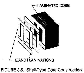
6 The laminations reduce certain losses which will be discussed later. The most effective transformer core is one that offers the best path for the most lines of flux with the least magnetic and electrical energy loss. Two main shapes of cores are used in laminated steel-core transformers: the hollow core and the shell core. The hollow core is shaped with a square through the center (Figure 8-3). The core is made up of many laminations of steel. Figure 8-4 shows how the transformer windings are wrapped around both sides of the core. The shell core is the most popular and efficient transformer (Figures 8-5 through 8-7).
7
8 As shown, each layer of the core consists of E- and I-shaped sections of metal. These sections are butted together to form laminations. The laminations are insulated from each other and then pressed together to form a core. TRANSFORMER WINDINGS Two wires called windings are wound around the core. Each winding is electrically insulated from the other. The terminals are marked according to the voltage: H indicates the higher voltage, and X indicates the lesser voltage. Figure 8-8 shows examples of this.
9 Additionally, H1 and X1 indicate polarity. Since AC is constantly changing polarity, the H1 and X1 indicate that the polarities at both these terminals are identical during the same instant in time. At the same moment H1 has current moving through it in a given direction, the induced current through terminal X1 is moving in the same direction. When H1 and X1 are directly opposite each other, a condition known as subtractive polarity is formed (Figure 8-9 view B). When the H1 and the X1 are diagonally positioned, a condition known as additive polarity is formed (view A).
10 Another form of polarity marking is through the use of dots. Dot notation is used with diagrams to express which terminals are positive at the same instant in time (Figure 8-10).
11 All transformers are not wired the same way, and improper connections can damage the entire electrical circuit. The terms "additive polarity" and "subtractive polarity" come from the means of testing unmarked transformers. Do not connect a transformer opposite to its intended purpose. Do not connect a step-down transformer for step-up application because the internal stresses set up within the transformer may damage it. SCHEMATIC SYMBOLS FOR TRANSFORMERS Figure 8-11 shows typical schematic symbols for transformers. View A shows the symbol for an air-core transformer. Views B and C show iron-core transformers. The bars between the windings indicate an iron core. Frequently, additional connections are made to the transformer windings at points other than the ends of the windings. These additional connections are called taps. When a tap is connected to the center of the winding, it is called center tap. View C shows the schematic representation of a centertapped iron-core transformer.
12 NO-LOAD CONDITION A transformer can supply voltages that are usually higher or lower than the source voltage. This is done through mutual induction, which takes place when the changing magnetic field produced by the primary voltage cuts the secondary winding. A no-load condition exists when a voltage is applied to the primary, but no load is connected to the secondary (Figure 8-12). Because of the open switch, there is no current flowing in the secondary winding. With the switch open and an AC voltage applied to the primary, there is, however, a very small amount of current, called exciting current, flowing in the primary. The exciting current "excites" the winding of the primary to create a magnetic field. The amount of the exciting current is determined by three factors, which are all controlled by transformer action: The amount of voltage applied. The resistance of the primary winding's wire and core losses. The inductive reactance which depends on the frequency of the exciting current. This very small amount of exciting current serves two functions: Most of the exciting energy is used to support the magnetic field of the primary. A small amount of energy is used to overcome the resistance of the wire and core. This is dissipated in the form of heat (power loss). Exciting current will flow in the primary winding at all times to maintain this magnetic field, but no transfer of energy will take place as long as the secondary circuit is open. WARNING
13 The open secondary leads provide a potential hazard to personnel. Should a path between the secondary leads develop, current will result. The soldier should never come in contact with the exposed secondary leads when the primary leads are energized. COUNTER ELECTROMOTIVE FORCE When an AC flows through a primary winding, a magnetic field is established around the winding. As the lines of flux expand outward, relative motion is present, and a counter EMF is induced in the winding. Flux leaves the primary at the north pole and enters the primary at the south pole. The CEMF induced in the primary has a polarity that opposes the applied voltage, thus opposing the flow of current in the primary. It is the CEMF that limits the exciting current to a very low value. VOLTAGE IN THE SECONDARY Figure 8-12 shows a voltage is induced into the secondary winding of a transformer. As the exciting current flows through the primary, magnetic lines of force are generated. During this time, while current is increasing in the primary, magnetic lines of force expand outward from the primary and cut the secondary. A voltage is induced into a winding when magnetic lines cut across it. Therefore, the voltage across the primary causes a voltage to be induced across the secondary. TURNS AND VOLTAGE RATIOS The total voltage induced into the secondary winding of a transformer is determined mainly by the ratio of the number of turns in the primary to the number of turns in the secondary and by the amount of voltage applied to the primary. Figure 8-13 view A shows a transformer whose primary consists of 10 turns of wire and whose secondary consists of a single turn of wire. As lines of flux generated by the primary expand and collapse, they cut both the 10 turns of the primary and the single turn of the secondary. Since the length of the wire in the secondary is about the same as the length of the wire in each turn of the primary, CEMF induced into the secondary will be the same as the EMF induced into each turn in the primary. This means that if the voltage applied to the primary winding is 10 volts, the CEMF in the primary is almost 10 volts. Thus, each turn in the primary will have an induced CEMF of about 1/10th of the total applied voltage, or 1 volt. Since the same flux lines cut the turns in both the secondary and the primary, each turn will have an EMF of 1 volt induced into it. The transformer in Figure 8-13 view A has only one turn in the secondary thus, the EMF across the secondary is 1 volt.

14 The transformer in view B has a 10-turn primary and a 2-turn secondary. Since the flux induces 1 volt per turn, the total voltage across the secondary is 2 volts. The volts per turn are the same for both the primary and secondary windings. Since the CEMF in the primary is equal (or almost equal) to the applied voltage, a proportion may be set up to express the value of the voltage induced in terms of the voltage applied to the primary and the number of turns in each winding. This proportion also shows the relationship between the number of turns in each winding and the voltage across each winding. This proportion is expressed by the following equation: Where: Np = number of turns in the primary Ep = voltage applied to the primary Es = voltage induced in the secondary Ns = number of turns in the secondary The equation shows that the ratio of secondary voltage to primary voltage equals the ratio of secondary turns to primary turns. The equation can be written as -- (Ep) x (Ns) = (Es) x (Np) The following formulas are derived from the above equation:
15 If any three quantities in the above formulas are known, the fourth quantity can be calculated. Example: A transformer has 200 turns in the primary, 50 turns in the secondary, and 120 volts applied to the primary. What is the voltage across the secondary (Es)? Given: Np = 200 turns Ns = 50 turns Ep = 120 volts Es =? Es = 30 volts The transformer in the above problem has fewer turns in the secondary than the primary. As a result, there is less voltage across the secondary than across the primary. A transformer in which the voltage across the secondary is less than the voltage across the primary is called a step-down transformer. The ratio of a four-to-one step-down transformer is written 4:1. A transformer that has fewer turns in the primary than in the secondary will produce a greater voltage across the secondary than the voltage applied to the primary. A transformer in which the voltage across the secondary is greater than the voltage applied to the primary is called a step-up transformer. The ratio of a one-to-four step-up transformer is written as 1:4. In the two ratios, the value of the primary winding is always stated first. EFFECT OF A LOAD When an electrical load is connected across the secondary winding of a transformer, current flows through the secondary and the load. The magnetic field produced by the current in the secondary interacts with the magnetic field produced by the current in the

16 primary. This interaction results from the mutual inductance between the primary and secondary windings. POWER RELATIONSHIP BETWEEN PRIMARY AND SECONDARY WINDINGS The turns ratio of a transformer affects current as well as voltage. If voltage is doubled in the secondary, current is halved in the secondary. Conversely, if voltage is halved in the secondary, current is doubled in the secondary. In this manner, all the power delivered to the primary by the source is also delivered to the load by the secondary (minus whatever power is consumed by the transformer in the form of losses). In the transformer shown in Figure 8-14, the turns ratio is 20:1. If the input to the primary is 10 amperes at 450 volts, the power in the primary is 4,500 watts (P = I x E). If the transformer has no losses, 4,500 watts is delivered to the secondary. The secondary steps down the voltage to 22.5 volts and will increase the current to 200 amperes. Thus, the power delivered to the load by the secondary is P = E x I = 22.5 volts x 200 amps = 4,500 watts. The reason for this is that when the number of turns in the secondary is decreased, the opposition to the flow of the current is also decreased. Hence, more current will flow in the secondary. If the turns ratio of the transformer is increased to 1:2 (step up), the number of turns on the secondary is twice the number of turns on the primary. This means the opposition to current is doubled. Thus, voltage is doubled, but current is
17 halved due to the increased opposition to current in the secondary. With the exception of the power consumed within the transformer, all power delivered to the primary by the source will be delivered to the load. The form of the power may change, but the power in the secondary almost always equals the power in the primary. This can be expressed in the formula: Ps = Pp - P1 Where: Ps = powered delivered to the load by the secondary Pp = power delivered to the primary by the source P1 = power losses in the transformer ACTUAL TRANSFORMER LOSSES Practical power transformers, although highly efficient, are not perfect devices. Small power transformers used with electrical components have an 80 to 90 percent efficiency range, while large distribution system transformers may have efficiencies exceeding 98 percent. The total power loss in a transformer is a combination of losses. One loss is due to the resistance in the conductors of the primary and secondary windings. This loss is called copper loss or I 2 R loss. As current increases through the resistance of the conductor, there is a drop in voltage proportional to the increase in current flow. This phenomenon is found wherever there is a resistance. Ohm's Law shows this. Example: The initial electrical load demands 10 amperes. The resistance in the transformer winding conductor is.4 ohms. The voltage drop across the winding conductor is 4 volts. E = I x R E = 10 amps x.4 ohms E = 4 volts If the electrical demand is increased and a current of 70 amperes is now required, the voltage drop across the winding conductor will increase. E = I x R E = 70 amps x.4 ohms E = 28 volts
18 As current flow increases, there is a resulting increase in heat. The resistance of copper increases as current and temperature increase. This further affects the voltage drop. This makes secondary voltage decrease as load is applied. Whenever current flows in a conductor, power is dissipated in the resistance of the conductor in the form of heat. The amount of power dissipated by the conductor is directly proportional to the resistance of the wire and to the square of the current through it. The greater the value of either the current or the resistance, the greater the power dissipated. P = I x E P = 70 amps x 28 volts P = 1,960 watts or P = I 2 x R P = 70 2 amps x.4 ohms P = 4,900 amps x.4 ohms P = 1,960 watts This is the power consumed or lost due to the resistance of the conductor. The resistance of a given conductor or winding is a function of the diameter of the conductor and its length. Large diameter, lower resistance wire is required for highcurrent-carrying applications whereas small diameter, higher resistance wire can be used for low-current-carrying applications. Two other losses are due to eddy currents and hysteresis in the core of the transformer. Copper loss, eddy current loss, and hysteresis loss result in undesirable conversion of electrical energy to heat energy. Eddy Current Loss The core of a transformer is usually constructed of some type of ferromagnetic material because it is a good conductor of magnetic lines of flux. Whenever the primary of an iron-core transformer is energized by an AC source, a fluctuating magnetic field is produced. This magnetic field cuts the conducting core
19 material and induces a voltage into it. The induced voltage causes random currents to flow through the core which dissipate power in the form of heat. These undesirable currents are eddy currents. To minimize the loss resulting from eddy currents, transformer cores are laminated. Since the thin, insulated laminations do not provide an easy path for current, eddy current losses are greatly reduced. Hysteresis Loss When a magnetic field is passed through a core, the core material becomes magnetized. To become magnetized, the domains within the core must align themselves with the external field. If the direction of the field is reversed, the domains must turn so that their poles are aligned with the new direction of the external field. Transformers normally operate at 60 hertz. Each tiny atomic particle domain must realign itself twice each cycle or a total of 120 times a second. The energy used to turn each domain is dissipated as heat within the iron core. This is hysteresis loss, which results from molecular friction. Hysteresis loss can be held to a small value by proper choice of core materials during the manufacturing process. TRANSFORMER EFFICIENCY To compute the efficiency of a transformer, the input power and the output power from the transformer must be known. The input power equals the product of the voltage applied to the primary and the current in the primary. The output power equals the product of the voltage across the secondary and the current in the secondary. The difference between the input power and the output power represents a power loss. This percentage of efficiency of a transformer is calculated using the standard efficiency formula: Efficiency (in percentage) = power out x 100 power in TRANSFORMER RATINGS When a transformer is to be used in a circuit, more than just the turns ratio must be considered. The voltage, current, and power-handling capabilities of the primary and secondary windings must be considered as well. The maximum voltage that can safely be applied to any winding is determined by the type and thickness of the insulation used. When a better (and thicker) insulation is used between the windings, a higher maximum voltage can be applied to the windings. The maximum current that can be carried by a transformer winding is determined by the diameter of the wire used for the winding. If current is excessive in a winding, a higher than ordinary amount of power will be dissipated by the winding in the form of heat. This
20 heat may become sufficiently high to cause the insulation around the wire to break down. If this happens, the transformer will become permanently damaged. The power-handling capability of a transformer depends on its ability to dissipate heat. If the heat can be safely removed, the power-handling capability of the transformer can be increased. This is sometimes done by immersing the transformer in oil or by using cooling fins. The power-handling capability of distribution system transformers is measured in the volt-ampere unit (kva). Smaller units generally used in resistive circuits are measured in the watt unit (KW). DISTRIBUTION TRANSFORMERS Step-down and isolation distribution transformers supply voltages to the various circuits in the electrical system. Distribution transformers are rated at 500 kva or less. These are the type found on Army vessels. They are the dry type and are air-cooled and drip-proof. They can operate at 30-degree inclinations. They are designed for ambient temperature operation of 40C and 50C. The high- and low-voltage windings in a distribution transformer can usually be distinguished by observing the diameter of the conductor. Since most transformers located on board ship are the stepdown type, the low-voltage winding will have the larger diameter conductor. This is because the power is not changed. The reduction in voltage means an increase of current. Current determines the diameter of the conductor. ISOLATION TRANSFORMERS Isolation transformers do not change either the power or the voltage and current levels. Instead, they provide an extra degree of protection to the distribution system for those circuits that are set aside for access by other than engineering personnel and the circuits that are available for unspecified electrical apparatus. Should one of these circuits have a catastrophic electrical casualty that prevents local circuit breakers and overloads from operating properly, the isolation transformer prevents a mechanical connection of the circuit with the rest of the distribution system. A catastrophic electrical problem will damage the transformer and allow time for the rest of the distribution system to react to the electrical problem. The isolation transformers effectively isolate these problem circuits from the rest of the single-phase distribution system. The areas under the added protection of the isolation transformer include galley equipment and "hotel" services (120-volt electrical outlets). TRANSFORMER TAPS Typical transformers used for electrical components and control circuits have several primary and/or secondary windings. Figure 8-15 shows the schematic symbol for a typical multitap transformer. For any given voltage across the primary, the voltage across each of the secondary windings is determined by the number of turns in each secondary.
21 A winding may be center-tapped like the secondary 350-volt winding in Figure To center-tap a winding means to connect a wire to the center of the coil, so that between this tap and either terminal of the winding there appears one-half of the voltage developed across the entire winding. AUTOTRANSFORMERS It is not always necessary to have two or more separate and distinct windings in a transformer. Figure 8-16 is a schematic diagram of an autotransformer. A single winding is tapped to produce what is electrically a primary and secondary winding.
22 Through inductance, the magnetic field from the power supply can produce a CEMF into the primary winding as well as an EMF into the secondary winding. Voltage is selfinduced into every coil of wire. Example: *Assume that 208 volts is applied to the autotransformer in Figure The primary includes all the turns, but the secondary includes only half the turns. The turns ratio is 2:1. Secondary voltage is -- There is a 10.4-ohm resistive load. Load current is --
23 It may be hard at first to understand how the secondary can have twice the primary current. After all, the primary and secondary are the same coil. Secondary current, however, is the sum of two separate currents. One is primary current which also flows in the secondary circuit. The other is produced by the back-voltage (CEMF), which is selfinduced in the secondary part of the coil. The primary current of 5 amperes is conducted to the secondary current. The other 5 amperes is transformed in the transformer.* The autotransformer is used extensively for reduced voltage starting of larger motors, such as the fire pump. This is one of the most effective ways to hold the line current and voltage to a minimum when a maximum current (or torque per line ampere) is required at the motor. The autotransformer is used for motor starting. It is never used to supply feeders or branch circuits in the distribution system. Figure 8-18 view B shows a damaged autotransformer. If this type of casualty took place, the voltage to the load would increase to the value available at the primary side. This could be electrically devastating to all the electrical loads connected to the secondary side.
24 TRANSFORMER SAFETY If transformers are being worked on or inspected, the following additional rules apply: Remove the transformer from all power sources in the primary and secondary circuitry. Remove all the fuses from the power source. Trip circuit breakers and take action to prevent their accidental resetting. Short out transformer secondaries before connecting and disconnecting equipment. To prevent potentially high voltage and current levels, always connect a load to the secondary side of the transformer before energizing the primary. The voltmeter is an excellent high-resistance load when connected with alligator clips. *The area between the asterisks (*) is reprinted with permission, copyright by Goodheart- Willcox.
Walchand Institute of Technology. Basic Electrical and Electronics Engineering. Transformer
 Walchand Institute of Technology Basic Electrical and Electronics Engineering Transformer 1. What is transformer? explain working principle of transformer. Electrical power transformer is a static device
SECTION 3 BASIC AUTOMATIC CONTROLS UNIT 12 BASIC ELECTRICITY AND MAGNETISM. Unit Objectives. Unit Objectives 2/29/2012
 SECTION 3 BASIC AUTOMATIC CONTROLS UNIT 12 BASIC ELECTRICITY AND MAGNETISM Unit Objectives Describe the structure of an atom. Identify atoms with a positive charge and atoms with a negative charge. Explain
Single-Phase Transformation Review
 Single-Phase Transformation Review S T U D E N T M A N U A L March 2, 2005 2 STUDENT TRAINING MANUAL Prerequisites: None Objectives: Given the Construction Standards manual and a formula sheet, you will
Transformers. ELG3311: Habash,
 Transformers A transformer is a device that changes AC electric power at one voltage level to AC electric power at another voltage level through the action of magnetic field. t consists of two or more
1 K Hinds 2012 TRANSFORMERS
 1 K Hinds 2012 TRANSFORMERS A transformer changes electrical energy of a given voltage into electrical energy at a different voltage level. It consists of two coils which are not electrically connected,
TRANSFORMER THEORY. Mutual Induction
 Transformers Transformers are used extensively for AC power transmissions and for various control and indication circuits. Knowledge of the basic theory of how these components operate is necessary to
Inductance in DC Circuits
 Inductance in DC Circuits Anurag Srivastava Concept: Inductance is characterized by the behavior of a coil of wire in resisting any change of electric current through the coil. Arising from Faraday's law,
UNIVERSITY OF TECHNOLOGY By: Fadhil A. Hasan ELECTRICAL MACHINES
 UNIVERSITY OF TECHNOLOGY DEPARTMENT OF ELECTRICAL ENGINEERING Year: Second 2016-2017 By: Fadhil A. Hasan ELECTRICAL MACHINES І Module-II: AC Transformers o Single phase transformers o Three-phase transformers
Trade of Electrician. The Transformer
 Trade of Electrician Standards Based Apprenticeship The Transformer Phase 2 Module No. 2.1 Unit No. 2.1.10 COURSE NOTES Created by Gerry Ryan - Galway TC Revision 1 April 2000 by Gerry Ryan - Galway TC
~=E.i!=h. Pre-certification Transformers
 7 Transformers Section 26 of the electrical code governs the use and installations of transformers. A transformer is a static device used to transfer energy from one alternating current circuit to another.
Cornerstone Electronics Technology and Robotics Week 32 Transformers
 Cornerstone Electronics Technology and Robotics Week 32 Transformers Administration: o Prayer o Turn in quiz Electricity and Electronics, Section 12.1, Transformer Theory: o A transformer is a device that
Electrical Theory 2 Lessons for Fall Semester:
 Electrical Theory 2 Lessons for Fall Semester: Lesson 1 Magnetism Lesson 2 Introduction to AC Theory Lesson 3 Lesson 4 Capacitance and Capacitive Reactance Lesson 5 Impedance and AC Circuits Lesson 6 AC
3. What is hysteresis loss? Also mention a method to minimize the loss. (N-11, N-12)
") DHANALAKSHMI COLLEGE OF ENGINEERING, CHENNAI DEPARTMENT OF ELECTRICAL AND ELECTRONICS ENGINEERING EE 6401 ELECTRICAL MACHINES I UNIT I : MAGNETIC CIRCUITS AND MAGNETIC MATERIALS Part A (2 Marks) 1. List
DHANALAKSHMI COLLEGE OF ENGINEERING, CHENNAI DEPARTMENT OF ELECTRICAL AND ELECTRONICS ENGINEERING EE 6401 ELECTRICAL MACHINES I UNIT I : MAGNETIC CIRCUITS AND MAGNETIC MATERIALS Part A (2 Marks) 1. List
Copper Sheathed Cable Sheath Currents
 Pyrotenax Copper heathed Cable heath Currents ingle Conductor Cable ingle conductor cables present certain application considerations that do not arise in multiconductor cable installations. These considerations
CHAPTER 5 CONCEPTS OF ALTERNATING CURRENT
 CHAPTER 5 CONCEPTS OF ALTERNATING CURRENT INTRODUCTION Thus far this text has dealt with direct current (DC); that is, current that does not change direction. However, a coil rotating in a magnetic field
Unit 3 Magnetism...21 Introduction The Natural Magnet Magnetic Polarities Magnetic Compass...21
 Chapter 1 Electrical Fundamentals Unit 1 Matter...3 Introduction...3 1.1 Matter...3 1.2 Atomic Theory...3 1.3 Law of Electrical Charges...4 1.4 Law of Atomic Charges...4 Negative Atomic Charge...4 Positive
Preface...x Chapter 1 Electrical Fundamentals
 Preface...x Chapter 1 Electrical Fundamentals Unit 1 Matter...3 Introduction...3 1.1 Matter...3 1.2 Atomic Theory...3 1.3 Law of Electrical Charges...4 1.4 Law of Atomic Charges...5 Negative Atomic Charge...5
TRANSFORMER OPERATION
 Chapter 3 TRANSFORMER OPERATION 1 A transformer is a static device (no moving parts) used to transfer energy from one AC circuit to another. This transfer of energy may involve an increase or decrease
CHAPTER 4. Distribution Transformers
 CHAPTER 4 Distribution Transformers Introduction A transformer is an electrical device that transfers energy from one circuit to another purely by magnetic coupling. Relative motion of the parts of the
Practical Tricks with Transformers. Larry Weinstein K0NA
 Practical Tricks with Transformers Larry Weinstein K0NA Practical Tricks with Transformers Quick review of inductance and magnetics Switching inductive loads How many voltages can we get out of a $10 Home
Chapter 16: Mutual Inductance
 Chapter 16: Mutual Inductance Instructor: Jean-François MILLITHALER http://faculty.uml.edu/jeanfrancois_millithaler/funelec/spring2017 Slide 1 Mutual Inductance When two coils are placed close to each
KNOW MORE ABOUT THE TRANSFORMERS. Glossary Transformers
 KNOW MORE ABOUT THE TRANSFORMERS Glossary Transformers Ambient temperature The existing temperature of the atmosphere surrounding a transformer installation. Ampere The practical unit of electric current.
CONSTRUCTION ELECTRICIAN APPRENTICESHIP PROGRAM Line H: Install Electrical Equipment H-2 LEARNING GUIDE H-2 INSTALL TRANSFORMERS
 CONSTRUCTION ELECTRICIAN APPRENTICESHIP PROGRAM Level 2 Line H: Install Electrical Equipment H-2 LEARNING GUIDE H-2 INSTALL TRANSFORMERS Foreword The Industry Training Authority (ITA) is pleased to release
Introduction. A closed loop of wire is not an electrical circuit, a circuit requires
 The Law of Charges Opposite charges attract like charges repel Lines of force can never cross each other The values are equal but the effect is opposite Strength of the attraction is exponential to its
Review 6. unlike poles cause the magnets to attract. like poles cause the magnets to repel.
 Review 6 1. The two characteristics of all magnets are: they attract and hold Iron, and, if free to move, they will assume roughly a south - north position. 2. Lines of flux always leave the north pole
UNIT II MEASUREMENT OF POWER & ENERGY
 UNIT II MEASUREMENT OF POWER & ENERGY Dynamometer type wattmeter works on a very simple principle which is stated as "when any current carrying conductor is placed inside a magnetic field, it experiences
DESIGN AND CONSTRUCTION OF 1500VA VARIABLE OUTPUT STEP DOWN TRANSFORMER
 DESIGN AND CONSTRUCTION OF 1500VA VARIABLE OUTPUT STEP DOWN TRANSFORMER OGUNDARE AYOADE B., OMOGOYE O. SAMUEL & OLUWASANYA OMOTAYO J. Department of Electrical/Electronic engineering, Lagos State Polytechnic,
MAHARASHTRA STATE BOARD OF TECHNICAL EDUCATION
 Important Instructions to examiners: 1) The answers should be examined by key words and not as word-to-word as given in the model answer scheme. 2) The model answer and the answer written by candidate
Electrical Machines I : Transformers
 UNIT TRANSFORMERS PART A (Q&A) 1. What is step down transformer? The transformer used to step down the voltage from primary to secondary is called as step down transformer. (Ex: /11).. Draw the noload
Electrical Machines (EE-343) For TE (ELECTRICAL)
 For TE (ELECTRICAL)") PRACTICALWORKBOOK Electrical Machines (EE-343) For TE (ELECTRICAL) Name: Roll Number: Year: Batch: Section: Semester: Department: N.E.D University of Engineering &Technology, Karachi Electrical Machines
PRACTICALWORKBOOK Electrical Machines (EE-343) For TE (ELECTRICAL) Name: Roll Number: Year: Batch: Section: Semester: Department: N.E.D University of Engineering &Technology, Karachi Electrical Machines
A Practical Guide to Free Energy Devices
 A Practical Guide to Free Energy Devices Part PatD14: Last updated: 25th February 2006 Author: Patrick J. Kelly This patent application shows the details of a device which it is claimed, can produce sufficient
CHAPTER 2. Transformers. Dr Gamal Sowilam
 CHAPTER Transformers Dr Gamal Sowilam Introduction A transformer is a static machine. It is not an energy conversion device, it is indispensable in many energy conversion systems. A transformer essentially
Table of Contents. Table of Figures. Table of Tables
 Abstract The aim of this report is to investigate and test a transformer and check if it is good to use by doing the following tests continuity test, insulation test, polarity test, open circuit test,
Introduction. Inductors in AC Circuits.
 Module 3 AC Theory What you ll learn in Module 3. Section 3.1 Electromagnetic Induction. Magnetic Fields around Conductors. The Solenoid. Section 3.2 Inductance & Back e.m.f. The Unit of Inductance. Factors
EEE 202 ELECTRO-TECHNIC LAB. PART 7 THEORY
 EEE 0 ELECTRO-TECHNIC LAB. PART 7 THEORY Yrd. Doç. Dr. Serhan Yarkan Arş. Gör. Dilara Albayrak İSTANBUL COMMERCE UNIVERSITY Contents EXAMINATION OF LC FILTERS... 0.1 INTRODUCTION... EXAMINATION OF TRANSFORMER...
Inductance, capacitance and resistance
 Inductance, capacitance and resistance As previously discussed inductors and capacitors create loads on a circuit. This is called reactance. It varies depending on current and frequency. At no frequency,
Back to the Basics Current Transformer (CT) Testing
 Testing") Back to the Basics Current Transformer (CT) Testing As test equipment becomes more sophisticated with better features and accuracy, we risk turning our field personnel into test set operators instead of
Back to the Basics Current Transformer (CT) Testing As test equipment becomes more sophisticated with better features and accuracy, we risk turning our field personnel into test set operators instead of
Transformers. gpmacademics.weebly.com
 TRANSFORMERS Syllabus: Principles of operation, Constructional Details, Losses and efficiency, Regulation of Transformer, Testing: OC & SC test. TRANSFORMER: It is a static device which transfers electric
By Gill ( ) PDF created with FinePrint pdffactory trial version
 PDF created with FinePrint pdffactory trial version") By Gill (www.angelfire.com/al4/gill ) 1 Introduction One of the main reasons of adopting a.c. system instead of d.c. for generation, transmission and distribution of electrical power is that alternatin
By Gill (www.angelfire.com/al4/gill ) 1 Introduction One of the main reasons of adopting a.c. system instead of d.c. for generation, transmission and distribution of electrical power is that alternatin
Generator Advanced Concepts
 Generator Advanced Concepts Common Topics, The Practical Side Machine Output Voltage Equation Pitch Harmonics Circulating Currents when Paralleling Reactances and Time Constants Three Generator Curves
TRANSFORMERS PART A. 2. What is the turns ratio and transformer ratio of transformer? Turns ratio = N2/ N1 Transformer = E2/E1 = I1/ I2 =K
 UNIT II TRANSFORMERS PART A 1. Define a transformer? A transformer is a static device which changes the alternating voltage from one level to another. 2. What is the turns ratio and transformer ratio of
AUTO-TRANSFORMER. This is having only one winding; part of this winding is common to both primary and secondary.
 AUTO-TRANSFORMER This is having only one winding; part of this winding is common to both primary and secondary. In 2-winding transformer both primary and secondary windings are electrically isolated, but
Basic Electrical Training
 Basic Electrical Training Electricians Tools Explain how various hand tools are used by an electrician Discuss the safe use of hand tools and power tools Perform basic calculations and measurement conversions
Type KLF Generator Field Protection-Loss of Field Relay
 Supersedes DB 41-745B pages 1-4, dated June, 1989 Mailed to: E, D, C/41-700A ABB Power T&D Company Inc. Relay Division Coral Springs, FL Allentown, PA For Use With Delta Connected Potential Transformers
Faraday Laws of Electromagnetic Induction CLIL LESSON
 Faraday Laws of Electromagnetic Induction CLIL LESSON Experimental trials Michael Faraday-1931 This law shows the relationship between electric circuit and magnetic field A coil is connected to a galvanometer
Transformers. Dr. Gamal Sowilam
 Transformers Dr. Gamal Sowilam OBJECTIVES Become familiar with the flux linkages that exist between the coils of a transformer and how the voltages across the primary and secondary are established. Understand
END-OF-SUBCOURSE EXAMINATION
 END-OF-SUBCOURSE EXAMINATION Circle the letter of the correct answer to each question. When you have answered all of the questions, use a Number 2 pencil to transfer your answers to the TSC Form 59. 1.
ELECTRIC CURRENTS AND CIRCUITS By: Richard D. Beard P.E.
 ELECTRICAL POWER There are two types of electric power in use, direct current (dc) and alternating current (ac). The most common use of direct current is automotive, including storage batteries, starter
HPS Universal BUCK-BOOST TRANSFORMERS
 BUCK-BOOST TRANSFORMERS Single and Three Phase Potted Buck-Boost Transformers Buck-Boost Applications & Standard Specification... 80 Selecting Buck-Boost Transformers... 81 Single Phase Selection Tables...
Exercise 10. Transformers EXERCISE OBJECTIVE DISCUSSION OUTLINE DISCUSSION. Introduction to transformers
 Exercise 10 Transformers EXERCISE OBJECTIVE When you have completed this exercise, you will be familiar with the basic operating principles of transformers, as well as with the different ratios of transformers:
WELCOME TO THE LECTURE
 WLCOM TO TH LCTUR ON TRNFORMR Single Phase Transformer Three Phase Transformer Transformer transformer is a stationary electric machine which transfers electrical energy (power) from one voltage level
Load-Trainer Transformer Simulator
 Load-Trainer Transformer Simulator XFMR-4BUSHING Four Bushing Transformer Simulator Operation Manual Product Description 2 Components Set-Up 3 4 Simulator Description 4 Front Panel Description 5 Toggle
MAHARASHTRA STATE BOARD OF TECHNICAL EDUCATION
 Important Instructions to examiners: 1) The answers should be examined by key words and not as word-to-word as given in the model answer scheme. 2) The model answer and the answer written by candidate
Radar. Radio. Electronics. Television. .104f 4E011 UNITED ELECTRONICS LABORATORIES LOUISVILLE
 Electronics Radio Television.104f Radar UNITED ELECTRONICS LABORATORIES LOUISVILLE KENTUCKY REVISED 1967 4E011 1:1111E111611 COPYRIGHT 1956 UNITED ELECTRONICS LABORATORIES POWER SUPPLIES ASSIGNMENT 23
Load-Trainer Transformer Simulator
 Load-Trainer Transformer Simulator XFMR-3BUSHING Three Bushing Transformer Simulator Operation Manual C-00879 XFMR-3BUSHING (11-11-15) Product Description 2 Components 3 Set-Up 4 Simulator Description
AEIJST - January Vol 5 - Issue 01 ISSN Minimization Iron Losses in Transformer
 Abstract Minimization Iron Losses in Transformer *P.Ramesh *MIE, MISTE It is almost impossible to reduce the iron losses completely; however these can be reduced to a certain extent. Here we have made
EE 340 Power Transformers
 EE 340 Power Transformers Preliminary considerations A transformer is a device that converts one AC voltage to another AC voltage at the same frequency. It consists of one or more coil(s) of wire wrapped
El-Hawary, M.E. The Transformer Electrical Energy Systems. Series Ed. Leo Grigsby Boca Raton: CRC Press LLC, 2000
 El-Hawary, M.E. The Transformer Electrical Energy Systems. Series Ed. Leo Grigsby Boca Raton: CRC Press LLC, 000 97 Chapter 4 THE TRANSFORMER 4. NTRODUCTON The transformer is a valuable apparatus in electrical
Electromagnet Motor Generator
 Magnetism and Electromagnetic Induction Study Guide Chapter 36 & 37 Key Terms: Magnetic Pole Magnetic Field Magnetic Domain Electromagnet Motor Generator Electromagnetic Induction Faraday s Law Transformer
Advanced electromagnetism and electromagnetic induction
 Advanced electromagnetism and electromagnetic induction This worksheet and all related files are licensed under the Creative Commons Attribution License, version 1.0. To view a copy of this license, visit
Unit FE-5 Foundation Electricity: Electrical Machines
 Unit FE-5 Foundation Electricity: Electrical Machines What this unit is about Power networks consist of large number of interconnected hardware. This unit deals specifically with two types of hardware:
Variable Transformers Product Design & Engineering Data
 Variable Transformers Product Design & Engineering Data Product Design & Engineering Data Type 1010B Cutaway General Information STACO ENERGY PRODUCTS CO. is a leading manufacturer of variable transformers,
Inductors & Resonance
 Inductors & Resonance The Inductor This figure shows a conductor carrying a current. A magnetic field is set up around the conductor as concentric circles. If a coil of wire has a current flowing through
CHAPTER 8: ELECTROMAGNETISM
 CHAPTER 8: ELECTROMAGNETISM 8.1: MAGNETIC EFFECT OF A CURRENT-CARRYING CONDUCTOR Electromagnets 1. Conductor is a material that can flow.. 2. Electromagnetism is the study of the relationship between.and..
BUCK-BOOST TRANSFORMERS
 Where Are Buck-Boost Transformers Used? A typical buck-boost application is 120 volts in, 12 volts out for low voltage lighting or control circuitry. In most applications, this low voltage transformer
Table of Contents. Introduction...2 Conductors and Insulators...3 Current, Voltage, and Resistance...6
 Table of Contents Introduction...2 Conductors and Insulators...3 Current, Voltage, and Resistance...6 Ohm s Law... 11 DC Circuits... 13 Magnetism...20 Alternating Current...23 Inductance and Capacitance...30
Basics of electrical transformer
 Visit: https://engineeringbasic.com Complete basics and theory of Electrical Transformer Electrical Transformer is the most used electrical machine in power system. Both in the power transmission and distribution
Basics of Electricity
 Basics of Electricity A quickstep Online Course Siemens industry, Inc. www.usa.siemens.com/step Trademarks Siemens is a trademark of Siemens AG. Product names mentioned may be trademarks or registered
Chapter 11. Alternating Current
 Unit-2 ECE131 BEEE Chapter 11 Alternating Current Objectives After completing this chapter, you will be able to: Describe how an AC voltage is produced with an AC generator (alternator) Define alternation,
Electrical Theory. Power Principles and Phase Angle. PJM State & Member Training Dept. PJM /22/2018
 Electrical Theory Power Principles and Phase Angle PJM State & Member Training Dept. PJM 2018 Objectives At the end of this presentation the learner will be able to: Identify the characteristics of Sine
SINGLE PHASE BUCK & BOOST TRANSFORMERS INSTRUCTION MANUAL
 SINGLE PHASE INSTRUCTION MANUAL DIAGRAM D This manual applies to all single-phase buck & boost transformers sold by Larson Electronics. Please refer to the connection diagram on pages 4-6 for properly
Description & Applications Questions & Answers Selection Charts Single Phase Selection Charts Three Phase...
 SECTION BUCK-BOOST TRANSFORMERS A simple and economical way to correct offstandard voltages... from 95 to 500 volts; single and three phase, in sizes up to 60 kva. Simplified buck-boost rating charts make
I p = V s = N s I s V p N p
 UNIT G485 Module 1 5.1.3 Electromagnetism 11 For an IDEAL transformer : electrical power input = electrical power output to the primary coil from the secondary coil Primary current x primary voltage =
INSTALLATION, OPERATION AND MAINTENANCE GUIDE
 INSTALLATION, OPERATION AND MAINTENANCE GUIDE FOR INDOOR/OUTDOOR SINGLE PHASE ENCAPSULATED TRANSFORMERS Indoor/Outdoor Encapsulated Transformers The pictures used in this guide are only a representation
EEE3441 Electrical Machines Department of Electrical Engineering. Lecture. Basic Operating Principles of Transformers
 Department of Electrical Engineering Lecture Basic Operating Principles of Transformers In this Lecture Basic operating principles of following transformers are introduced Single-phase Transformers Three-phase
Engineering Science OUTCOME 4 - TUTORIAL 3 CONTENTS. 1. Transformers
 Unit : Unit code: QCF Level: 4 Credit value: 5 SYLLABUS Engineering Science L/60/404 OUTCOME 4 - TUTOIAL 3 Be able to apply single phase AC theory to solve electrical and electronic engineering problems
Power. Power is the rate of using energy in joules per second 1 joule per second Is 1 Watt
 3 phase Power All we need electricity for is as a source of transport for energy. We can connect to a battery, which is a source of stored energy. Or we can plug into and electric socket at home or in
Three-Phase Induction Motors. By Sintayehu Challa ECEg332:-Electrical Machine I
 Three-Phase Induction Motors 1 2 3 Classification of AC Machines 1. According to the type of current Single Phase and Three phase 2. According to Speed Constant Speed, Variable Speed and Adjustable Speed
Conceptual Physics. Chapter 23: ELECTRIC CURRENT
 Conceptual Physics Chapter 23: ELECTRIC CURRENT Electric Potential Unit of measurement: volt, 1 volt 1 joule 1 coulomb Example: Twice the charge in same location has twice the electric potential energy
Aligarh College of Engineering & Technology (College Code: 109) Affiliated to UPTU, Approved by AICTE Electrical Engg.
 Affiliated to UPTU, Approved by AICTE Electrical Engg.") Aligarh College of Engineering & Technology (College Code: 19) Electrical Engg. (EE-11/21) Unit-I DC Network Theory 1. Distinguish the following terms: (a) Active and passive elements (b) Linearity and
Aligarh College of Engineering & Technology (College Code: 19) Electrical Engg. (EE-11/21) Unit-I DC Network Theory 1. Distinguish the following terms: (a) Active and passive elements (b) Linearity and
PHYS 1441 Section 001 Lecture #22 Wednesday, Nov. 29, 2017
 PHYS 1441 Section 001 Lecture #22 Chapter 29:EM Induction & Faraday s Law Transformer Electric Field Due to Changing Magnetic Flux Chapter 30: Inductance Mutual and Self Inductance Energy Stored in Magnetic
1. Explain in detail the constructional details and working of DC motor.
 DHANALAKSHMI SRINIVASAN INSTITUTE OF RESEARCH AND TECHNOLOGY, PERAMBALUR DEPT OF ECE EC6352-ELECTRICAL ENGINEERING AND INSTRUMENTATION UNIT 1 PART B 1. Explain in detail the constructional details and
3.1.Introduction. Synchronous Machines
 3.1.Introduction Synchronous Machines A synchronous machine is an ac rotating machine whose speed under steady state condition is proportional to the frequency of the current in its armature. The magnetic
INSTITUTE OF AERONAUTICAL ENGINEERING (Autonomous) Dundigal, Hyderabad
 Dundigal, Hyderabad") INSTITUTE OF AERONAUTICAL ENGINEERING (Autonomous) Dundigal, Hyderabad -00 03 ELECTRCIAL AND ELECTRONICS ENGINEERING TUTORIAL QUESTION BANK Course Name Course Code Class Branch : DC MACHINES AND TRANSFORMERS
INSTITUTE OF AERONAUTICAL ENGINEERING (Autonomous) Dundigal, Hyderabad -00 03 ELECTRCIAL AND ELECTRONICS ENGINEERING TUTORIAL QUESTION BANK Course Name Course Code Class Branch : DC MACHINES AND TRANSFORMERS
DOWNLOAD OR READ : TRANSFORMERS PDF EBOOK EPUB MOBI
 DOWNLOAD OR READ : TRANSFORMERS PDF EBOOK EPUB MOBI Page 1 Page 2 transformers transformers pdf transformers Transformers: Basics, Maintenance, and Diagnostics. 11. due to voltages induced in the steel
3.0 CHARACTERISTICS. Type CKO Overcurrent Relay. switch, which allows the operation indicator target to drop.
 41-101.3A Type CKO Overcurrent Relay switch, which allows the operation indicator target to drop. The front spring, in addition to holding the target, provides restraint for the armature and thus controls
OD1647 ELECTRONIC PRINCIPLES
 SUBCOURSE OD1647 EDITION 8 ELECTRONIC PRINCIPLES ELECTRONIC PRINCIPLES SUBCOURSE OD1647 EDITION 8 United States Army Combined Arms Support Command Fort Lee, VA 23801 1809 7 Credit Hours NEW: 1988 GENERAL
REQUIRED SKILLS AND KNOWLEDGE UEENEEG101A. Electromagnetic devices and circuits. Topic and Description NIDA Lesson CARD # Magnetism encompassing:
 REQUIRED SKILLS AND KNOWLEDGE UEENEEG101A KS01-EG101A Electromagnetic devices and circuits T1 Magnetism encompassing: Topic and Description NIDA Lesson CARD # magnetic field pattern of bar and horse-shoe
VALLIAMMAI ENGINEERING COLLEGE
 VALLIAMMAI ENGINEERING COLLEGE SRM Nagar, Kattankulathur 603 203 DEPARTMENT OF ELECTRONICS AND INSTRUMENTATION ENGINEERING QUESTION BANK IV SEMESTER EI6402 ELECTRICAL MACHINES Regulation 2013 Academic
General Licensing Class Circuits
 General Licensing Class Circuits Valid July 1, 2011 Through June 30, 2015 1 Amateur Radio General Class Element 3 Course Presentation ELEMENT 3 SUB-ELEMENTS (Groupings) Your Passing CSCE Your New General
Radio and Electronics Fundamentals
 Amateur Radio License Class Radio and Electronics Fundamentals Presented by Steve Gallafent September 26, 2007 Radio and Electronics Fundamentals Voltage, Current, and Resistance Electric current is the
13 th Asian Physics Olympiad India Experimental Competition Wednesday, 2 nd May 2012
 13 th Asian Physics Olympiad India Experimental Competition Wednesday, nd May 01 Please first read the following instructions carefully: 1. The time available is ½ hours for each of the two experimental
National Marine Manufacturers Association Compliance Specialist Examination A.C. Electrical (2018 Model Year) ABYC E-11 Supplement 56
 ABYC E-11 Supplement 56") 1. Two Electrical Technicians are discussing markings that are required for AC wiring. Tech A says that AC conductors must be rated for 600 volts and must have their jackets and individual conductors marked
1. Two Electrical Technicians are discussing markings that are required for AC wiring. Tech A says that AC conductors must be rated for 600 volts and must have their jackets and individual conductors marked
Iron Powder Core Selection For RF Power Applications. Jim Cox Micrometals, Inc. Anaheim, CA
 HOME APPLICATION NOTES Iron Powder Core Selection For RF Power Applications Jim Cox Micrometals, Inc. Anaheim, CA Purpose: The purpose of this article is to present new information that will allow the
PHYS 1442 Section 004 Lecture #15
 PHYS 1442 Section 004 Lecture #15 Monday March 17, 2014 Dr. Andrew Brandt Chapter 21 Generator Transformer Inductance 3/17/2014 1 PHYS 1442-004, Dr. Andrew Brandt Announcements HW8 on Ch 21-22 will be
MCQ Questions. Elements of Electrical Engineering (EEE)
") MCQ Questions 1. The length of conductor is doubled and its area of cross section is also doubled, then the resistance will. a. Increase four time b. Remain unchanged c. Decrease to four times d. Change
MCQ Questions 1. The length of conductor is doubled and its area of cross section is also doubled, then the resistance will. a. Increase four time b. Remain unchanged c. Decrease to four times d. Change
N I N LI I. I t. (Note how L is independent of the current I.)
") UNIT- IV MAGNETICALLY COUPLED CIRCUITS Magnetically Coupled Circuits: Self inductance - Mutual inductance - Dot rule - Coefficient of coupling - Analysis of multi winding coupled circuits - Series, Parallel
UNIT- IV MAGNETICALLY COUPLED CIRCUITS Magnetically Coupled Circuits: Self inductance - Mutual inductance - Dot rule - Coefficient of coupling - Analysis of multi winding coupled circuits - Series, Parallel
ESO 210 Introduction to Electrical Engineering
 ESO 210 Introduction to Electrical Engineering Lecture-19 Magnetic Circuits and Introduction to Transformers 2 SERIES CONNECTION OF MUTUALLY COUPLED COILS A mutual term will alter the total inductance
SECTION 4 TRANSFORMERS. Yilu (Ellen) Liu. Associate Professor Electrical Engineering Department Virginia Tech University
 Liu. Associate Professor Electrical Engineering Department Virginia Tech University") SECTION 4 TRANSFORMERS Yilu (Ellen) Liu Associate Professor Electrical Engineering Department Virginia Tech University Analysis of Transformer Turns Ratio......................... 4.2 Analysis of a Step-Up
SECTION 4 TRANSFORMERS Yilu (Ellen) Liu Associate Professor Electrical Engineering Department Virginia Tech University Analysis of Transformer Turns Ratio......................... 4.2 Analysis of a Step-Up
INSTITUTE OF AERONAUTICAL ENGINEERING (Autonomous) Dundigal, Hyderabad
 Dundigal, Hyderabad") INSTITUTE OF AERONAUTICAL ENGINEERING (Autonomous) Dundigal, Hyderabad - 00 0 ELECTRICAL AND ELECTRONICS ENGINEERING QUESTION BANK Course Name Course Code Class Branch : ELECRICAL MACHINES - II : A0 :
INSTITUTE OF AERONAUTICAL ENGINEERING (Autonomous) Dundigal, Hyderabad - 00 0 ELECTRICAL AND ELECTRONICS ENGINEERING QUESTION BANK Course Name Course Code Class Branch : ELECRICAL MACHINES - II : A0 :