Iron Powder Core Selection For RF Power Applications. Jim Cox Micrometals, Inc. Anaheim, CA
|
|
|
- Debra Perkins
- 6 years ago
- Views:
Transcription

1 HOME APPLICATION NOTES Iron Powder Core Selection For RF Power Applications Jim Cox Micrometals, Inc. Anaheim, CA Purpose: The purpose of this article is to present new information that will allow the RF design engineer to select the proper iron powder core for inductors and transformers Handling power in the 250 khz to 5 MHz frequency range. Iron powder cores are commonly used to produce high Q inductors and transformers for selective circuits. Iron powder cores used in RF applications are composed of extremely small particles of highly pure carbonyl iron. The distributed air-gap of iron powder cores contributes to their rather low permeability and very good stability. In applications involving low-level signals, the choice of core size, material and winding is normally based on required Q and/or packaging requirements. A listing of the general magnetic properties of carbonyl iron powders are shown in Figure A. FIGURE A 1

2 Low level broadband transformers and RF chokes are commonly built on high permeability ferrite cores. Ferrites are a non-metallic ceramic ferromagnetic compound with a spinel crystalline structure. Ferrite cores have higher permeability than iron powder cores but are less stable. While much of the information presented here will be applicable to ferrite cores, the data presented is primarily intended for iron powder cores. Inductor and transformer applications involving higher power signals require additional considerations. A common misconception is that core saturation is the primary limiting factor in selecting a core for RF power applications. While it needs to be determined how much voltage drop or current flow a given inductor or transformer can support before a limit is reached, this limit will be either magnetic saturation or excessive temperature rise resulting from both winding (copper) and core material losses. Magnetic saturation is the point at which an increase in magnetization force does not result in any further increase in flux density. This implies that there will be a loss of permeability. An inductor will show a decrease in inductance and a transformer will show both a decrease in impedance and will not transform the additional signal. Carbonyl iron powders typically reach their maximum permeability at about 3000 gauss and then begin to saturate. They reach full saturation at approximately 10,000 gauss. This characteristic is illustrated in Figure B. FIGURE B With continuous sinewave signals, iron powder cores are limited by temperature rise resulting from losses rather than magnetic saturation. Temperature rise results from losses in both the winding and the core material. The fundamental winding losses are equal to I²R where I is the RMS current flowing in amperes and R is the effective AC resistance. At high frequency the current carried by a conductor tends to be concentrated near the surface. This is known as 2
3 skin effect. The skin depth of the AC current in a copper conductor at room temperature is described by: Skin Depth (cm) = 6.62 / f.5 where f is frequency in hertz. Figure C is a graphic representation showing AWG wire size versus frequency for a skin depth equal to the conductor radius. For example, at 1 MHz, a wire larger than #35 AWG will not be fully utilized and will thus show an increased AC resistance. Due to this, the use of a large number of strands of fine wire that are insulated from each other and interwoven can be useful in reducing the AC resistance of conductors at high frequency. Such a conductor is known as litz wire. Practical litz conductors are very effective at frequencies below 500 khz, but begin to lose effect above 3 MHz. FIGURE C Winding losses are an important consideration in properly designing higher power magnetic components. Further information on skin effect and the AC resistance of conductors can be found in the Radio Engineer s Handbook as well as a number of other references. Figures D, E and F show core loss graphs for three iron powder core materials (Micrometals, Inc. material 6, 2 and 15) ranging in permeability from 8.5 to 25. The losses generated by the core materials were determined experimentally. The total loss of a wound coil was measured and the losses due to the test set-up, the winding, and the core material were separated. The information presented is for the core material alone. 3

4 FIGURE D FIGURE E 4
 Temp.")
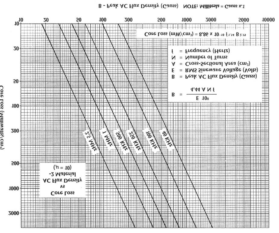
5 FIGURE F The core loss expressed in milliwatts per cubic centimeter as a function of peak AC flux density (DC flux does not generate core loss) for a number of frequencies from 40 khz to 5.0 MHz. The milliwatts per cubic centimeter dissipated by a core will generate temperature rise. The formula used to describe this relationship is: Power Dissipation (milliwatts) Temp. Rise (C ) = Surface Area (cm 2 ) This formula provides a reasonable approximation for the temperature rise of a core in free standing air. In other environments such as moving air or an enclosed case, other relationships will need to be used. With constant power dissipation, it typically takes a core about 2 hours to reach its final temperature. Applications involving low-duty or intermittent operation can time average the losses. It is important to limit the operating temperature of inductors and transformers using iron powder cores. Long term operation of iron powder cores above 80 C can cause a permanent reduction in both Q and inductance. A listing of the power dissipation in milliwatts per cubic centimeter for temperature rises of 10, 25 and 40 C for most of the common iron powder core sizes is shown in Figure G. For those not familiar with the part numbering system: A T30 is a toroidal core with an outside diameter of about 0.30 inches while a T400 is a 4.00 inch outside diameter toroid. It can be seen that the physically small parts can dissipate more power per unit volume than the physically large parts
6 Power dissipation in mw/cc As a function of temp rise Core 10 C 25 C 40 C T T T T T T T T T T T T T FIGURE G The peak AC flux density (Figures D, E and F) for sinewaves is described by Faraday s Law: 8 E 10 B = 4.44 A N f Where: B = peak AC flux density (gauss) (l gauss = 10-4 tesla) E = RMS sinewave voltage (Volts) A = core cross-sectional area (cm 2 ) N = number of Turns f = frequency (hertz) This form of Faraday s Law is generally more useful for transformer applications where the applied voltage is normally known. For an inductor, E = 2 π f L I Where: E = RMS Sinewave Voltage (volts) f = Frequency (hertz) L = Inductance (henries) I = RMS Current (amperes) Comparing the core loss characteristics of the three materials shown in figures D, E and F at a particular frequency does not indicate a significant difference in the power dissipated in milliwatts per cubic centimeter at a given AC flux density. However, with further investigation it becomes evident that for a given inductance and voltage the lower permeability materials generate less AC flux density and, thus, lower core loss, than the higher permeability materials. Coils wound on lower permeability materials, however, require more turns than higher permeability materials to produce the same inductance, and will, therefore produce greater winding loss. In general, the best compromise in performance will occur when the winding and core losses are approximately equal. 6

7 While the distribution of total loss between the core and the winding for any given frequency is dependent on the winding details as well as the physical size of the coil, it is useful to have a rough approximation of this distribution. Figure H illustrates this distribution for three iron powder core materials over the frequency range of 250 khz to 5.0 MHz with a typical single layer winding. This graph shows that at a frequency of 1 MHz, of the total loss generated in a typical coil wound on material 2, that about 40% of that loss is due to the winding. In the higher permeability material 15, at 1 MHz, about 10% of the total loss generated is due to the winding. With this guideline, it is then possible to estimate how much core loss can be tolerated without exceeding reasonable temperature rise limits. FIGURE H In an effort to take the basic core loss data that is expressed in magnetic terms and present it in more common engineering terms, application curves have been generated by Micrometals, Inc. The set of curves shown in Figure I graphs the maximum voltage as a function of inductance (and inductive reactance) for various core sizes in Micrometals material 2 at a frequency of 1 MHz for a temperature rise of 25 C due to core loss. These curves are based on continuous sinewave signals. A similar set of curves in terms of current as a function of inductance appears in figure J. Similar graphs are available for other frequencies and core materials from Micrometals, Inc. 7


8 FIGURE I FIGURE J MICROMETALS, INC E. LA PALMA AVENUE ANAHEIM, CALIFORNIA USA
9 The use of these curves can be illustrated with the following examples: 1) If an inductor application at 1 MHz requires 10 µh (microhenries) and the AC RMS current level is 1 ampere, figure J shows that a T68 size core will be required (Part number T68-2). It can also be seen in figure I that this condition corresponds to a voltage drop across this coil of about 70 volts. 2) To select a core for a transformer requiring 100 ohms of primary inductive reactance and capable of supporting 200 volts rms, Figure I should be used. This shows that 100 ohms of reactance is equal to 15.9 µh and that a T157 size core will be required to support the 200 volts rms. Inductance ratings in microhenries for 100 turns are commonly provided by iron powder core manufacturers. The number of turns required to produce a desired inductance for a core with a known inductance rating is given by: required turns = 100 desired L (µh) L rating (µh/100 turns) In example (1) the T68-2 has an inductance rating of 57 µh for 100 turns and will thus require 42 turns for 10 µh. The T157-2 in example (2) has an inductance rating of 140 µh for 100 turns. The 15.9 µh will require 34 turns. In general, for inductors, the largest wire which will fit in a full single layer will produce the best results. A winding table with this information is available. It is further possible to define a power rating for the various core sizes. This power rating will be defined to be the product of the current flowing through a coil times the voltage being dropped across that coil. For a given temperature rise due to core loss, this product is independent of the number of turns wound on the core. Figure K shows this information for material at 2 MHz. 1 2 Power Rating for 25 C temp rise due to core loss Material 2 1 MHz Core Watts T30 21 T37 26 T44 37 T50 49 T68 88 T T T T T T T T FIGURE K 9
10 Conclusion: The selection of the core size and material for RF power inductors and transformers has typically relied on the cut and try method. New data and application information is now available which allows the design engineer to more easily and accurately select the optimum iron powder core size and material for these applications. 10
Iron Powder Cores for High Q Inductors By: Jim Cox - Micrometals, Inc.
 HOME APPLICATION NOTES Iron Powder Cores for High Q Inductors By: Jim Cox - Micrometals, Inc. SUBJECT: A brief overview will be given of the development of carbonyl iron powders. We will show how the magnetic
What is an Inductor? Token Electronics Industry Co., Ltd. Version: January 16, Web:
 Version: January 16, 2017 What is an Inductor? Web: www.token.com.tw Email: rfq@token.com.tw Token Electronics Industry Co., Ltd. Taiwan: No.137, Sec. 1, Zhongxing Rd., Wugu District, New Taipei City,
Magnetics Design. Specification, Performance and Economics
 Magnetics Design Specification, Performance and Economics W H I T E P A P E R MAGNETICS DESIGN SPECIFICATION, PERFORMANCE AND ECONOMICS By Paul Castillo Applications Engineer Datatronics Introduction The
eightolives.com QuickApp Toroid Design Copyright 2011 William Kaupinis All Rights Reserved
 QuickApp Toroid Design William_Kaupinis@ April 4, 2011 1 Abstract Ferrite and iron powder toroids are often used to create custom inductors and transformers in radio frequency (RF) applications. The finger-friendly
HOME APPLICATION NOTES
 HOME APPLICATION NOTES INDUCTOR DESIGNS FOR HIGH FREQUENCIES Powdered Iron "Flux Paths" can Eliminate Eddy Current 'Gap Effect' Winding Losses INTRODUCTION by Bruce Carsten for: MICROMETALS, Inc. There
Inductor Glossary. Token Electronics Industry Co., Ltd. Version: January 16, Web:
 Version: January 16, 2017 Inductor Glossary Web: www.token.com.tw Email: rfq@token.com.tw Token Electronics Industry Co., Ltd. Taiwan: No.137, Sec. 1, Zhongxing Rd., Wugu District, New Taipei City, Taiwan,
Glossary of Common Magnetic Terms
 Glossary of Common Magnetic Terms Copyright by Magnelab, Inc. 2009 Air Core A term used when no ferromagnetic core is used to obtain the required magnetic characteristics of a given coil. (see Core) Ampere
Review 6. unlike poles cause the magnets to attract. like poles cause the magnets to repel.
 Review 6 1. The two characteristics of all magnets are: they attract and hold Iron, and, if free to move, they will assume roughly a south - north position. 2. Lines of flux always leave the north pole
Renco Electronics, Inc.
 Abstract The operating frequency of most electronic circuits has been increasing since the late 1950 s. While the increase in frequency has reduced the overall weight and size of most consumer electronics
TOROIDAL CORES : IRON POWDER CORES
 1 von 19 19.07.2007 08:49 TOROIDAL CORES : IRON POWDER CORES Iron Powder Cores are made in numerous shapes and sizes: such as Toroidal Cores, E- cores, Shielded Coil Forms, Sleeves etc., each of which
GLOSSARY OF TERMS FLUX DENSITY:
 ADSL: Asymmetrical Digital Subscriber Line. Technology used to transmit/receive data and audio using the pair copper telephone lines with speed up to 8 Mbps. AMBIENT TEMPERATURE: The temperature surrounding
Topic 4 Practical Magnetic Design: Inductors and Coupled Inductors
 Topic 4 Practical Magnetic Design: Inductors and Coupled Inductors Louis Diana Agenda Theory of operation and design equations Design flow diagram discussion Inductance calculations Ampere s law for magnetizing
ELECTROMAGNETIC INDUCTION AND ALTERNATING CURRENT (Assignment)
") ELECTROMAGNETIC INDUCTION AND ALTERNATING CURRENT (Assignment) 1. In an A.C. circuit A ; the current leads the voltage by 30 0 and in circuit B, the current lags behind the voltage by 30 0. What is the
ELECTROMAGNETIC INDUCTION AND ALTERNATING CURRENT (Assignment) 1. In an A.C. circuit A ; the current leads the voltage by 30 0 and in circuit B, the current lags behind the voltage by 30 0. What is the
Components, those bits and pieces which make up
 COMPONENTS and Systems CHAPTER 1 Components, those bits and pieces which make up a radio frequency (RF) circuit, seem at times to be taken for granted. A capacitor is, after all, a capacitor isn t it?
V I S H A y I n T E R T E C H n O l O G y, I n C. In D u C T O R S In S T R u C TIO n A l INDuCtOR 101 Gu ID E w w w. v i s h a y.
 VISHAY INTERTECHNOLOGY, INC. INDUCTORS INDUCTOR 101 instructional Guide www.vishay.com Inductor 101 Inductor A passive component designed to resist changes in current. Inductors are often referred to as
20 meter bandstop filter notes
 1 Introduction 20 meter bandstop filter notes Kevin E. Schmidt, W9CF 6510 S. Roosevelt St. Tempe, AZ 85283 USA A shorted half-wavelength stub cut for 20 meters acts as a bandstop filter for 10 and 20 meters,
END-OF-SUBCOURSE EXAMINATION
 END-OF-SUBCOURSE EXAMINATION Circle the letter of the correct answer to each question. When you have answered all of the questions, use a Number 2 pencil to transfer your answers to the TSC Form 59. 1.
A Fresh Look at Design of Buck and Boost inductors for SMPS Converters
 A Fresh Look at Design of Buck and Boost inductors for SMPS Converters Authors: Weyman Lundquist, Carl Castro, both employees of West Coast Magnetics. Inductors are a critical component in buck and boost
Electrical Theory 2 Lessons for Fall Semester:
 Electrical Theory 2 Lessons for Fall Semester: Lesson 1 Magnetism Lesson 2 Introduction to AC Theory Lesson 3 Lesson 4 Capacitance and Capacitive Reactance Lesson 5 Impedance and AC Circuits Lesson 6 AC
TOROID : FT,T & BALUN
 TOROID : FT,T & BALUN By N.S. Harisankar - VU3NSH. Phone : (0491) 2576102 The Toroidal cores are grouped into two types. (a) powdered Iron and (b) Ferrites. The Ferrite materials are based on "Nickel-Zinc"
Inductors & Resonance
 Inductors & Resonance The Inductor This figure shows a conductor carrying a current. A magnetic field is set up around the conductor as concentric circles. If a coil of wire has a current flowing through
R. W. Erickson. Department of Electrical, Computer, and Energy Engineering University of Colorado, Boulder
 R. W. Erickson Department of Electrical, Computer, and Energy Engineering University of Colorado, Boulder 13.2.3 Leakage inductances + v 1 (t) i 1 (t) Φ l1 Φ M Φ l2 i 2 (t) + v 2 (t) Φ l1 Φ l2 i 1 (t)
Selecting the Best Inductor for Your DC-DC Converter Leonard Crane Coilcraft
 Selecting the Best Inductor for Your DC-DC Converter Leonard Crane Coilcraft Understanding the Data Sheet Abstract Proper inductor selection requires a good understanding of inductor performance and of
MAGNETIC POWDER CORES
 Ver.13 www.changsung.com MAGNETIC POWDER CORES Innovative Technological Advancements Move forward with Chang Sung Corporation. We are one of the main suppliers of cutting edge products to all our customers
Inductor and Transformer Design
 Inductor and Transformer Design 1 Introduction The conditioning of power flow in Power Electronic Systems (PES) is done through the use of electromagnetic elements (inductors and transformers). In this
Design Considerations
 Design Considerations Ferrite toroids provide an often convenient and very effective shape for many wide band, pulse and power transformers and inductors. The continuous magnetic path yields the highest
SMALLER-FASTER- OW R CO$T
 SMALLER-FASTER- OW R CO$T Magnetic Materials for Today s High-Power Fast-Paced Designs Donna Kepcia Technical Sales Manager Magnetics DISCUSSION OVERVIEW Semiconductor Materials, SiC, Silicon Carbide &
SMALLER-FASTER- OW R CO$T
 SMALLER-FASTER- OW R CO$T Magnetic Materials for Today s High-Power Fast-Paced Designs Donna Kepcia Technical Sales Manager Magnetics DISCUSSION OVERVIEW Semiconductor Materials, SiC, Silicon Carbide &
Application of Soft Ferrite Material: from EMC to RFID
 Application of Soft Ferrite Material: from EMC to RFID 26 April 2012 Alan Keenan Industrial Electronics GmbH in partnership with HF Technology & Fair-Rite Products Corp. www.fair-rite.com www.ie4u.eu Topics
West Coast Magnetics. Advancing Power Electronics FOIL WINDINGS FOR SMPS INDUCTORS AND TRANSFORMERS. Weyman Lundquist, CEO and Engineering Manager
 1 West Coast Magnetics Advancing Power Electronics FOIL WINDINGS FOR SMPS INDUCTORS AND TRANSFORMERS Weyman Lundquist, CEO and Engineering Manager TYPES OF WINDINGS 2 Solid wire Lowest cost Low DC resistance
Inductance in DC Circuits
 Inductance in DC Circuits Anurag Srivastava Concept: Inductance is characterized by the behavior of a coil of wire in resisting any change of electric current through the coil. Arising from Faraday's law,
Shielded Power Inductors
 Shielded Power Inductors MN509 Shielded inductor with minimum EMI Minimum power loss Non standard values available Low DC resistance Flat top for SMT operations Specifications Inductance tested at 100KHz
Design Considerations
 Design Considerations APPLICATION NOTES: Multi-hole cores provide specialized shapes that are sometimes more useful than single hole devices. One example is wide band transformers where good coupling between
VOLTECHNOTES. Transformer Basics VPN /1
 Transformer Basics VPN 104-039/1 TRANSFORMER BASICS Introduction Transformer design and test are sometimes viewed as an art rather than a science. Transformers are imperfect devices, and there will be
LEAKAGE FLUX CONSIDERATIONS ON KOOL Mµ E CORES
 LEAKAGE FLUX CONSIDERATIONS ON E CORES Michael W. Horgan Senior Applications Engineer Magnetics Division of Spang & Co. Butler, PA 163 Abstract Kool Mu, a Silicon-Aluminum-Iron powder, is a popular soft
Large Kool Mµ Core Shapes
 Large Kool Mµ Core Shapes TECHNICAL BULLETIN Ideal for high current inductors, large Kool Mµ geometries (E cores, U Cores and Blocks) offer all the advantages of Kool Mµ material, low core loss, excellent
Properties of Inductor and Applications
 LABORATORY Experiment 3 Properties of Inductor and Applications 1. Objectives To investigate the properties of inductor for different types of magnetic material To calculate the resonant frequency of a
Large Kool Mµ Core Shapes
 Large Kool Mµ Core Shapes TECHNICAL BULLETIN Ideal for high current inductors, large Kool Mµ geometries (E cores, U Cores and Blocks) offer all the advantages of Kool Mµ material, low core loss, excellent
STUDY AND DESIGN ASPECTS OF INDUCTORS FOR DC-DC CONVERTER
 STUDY AND DESIGN ASPECTS OF INDUCTORS FOR DC-DC CONVERTER 1 Nithya Subramanian, 2 R. Seyezhai 1 UG Student, Department of EEE, SSN College of Engineering, Chennai 2 Associate Professor, Department of EEE,
The design of Ruthroff broadband voltage transformers M. Ehrenfried G8JNJ
 The design of Ruthroff broadband voltage transformers M. Ehrenfried G8JNJ Introduction I started investigating balun construction as a result of various observations I made whilst building HF antennas.
ARNSW Balun Day. Balun construction
 ARNSW Balun Day Balun construction Typical Baluns All built from locally available components. Balun uses Most baluns are used to match the 50Ω output of a transceiver to an antenna. A centre fed dipole
Radio Frequency Electronics
 Radio Frequency Electronics Preliminaries II Guglielmo Giovanni Maria Marconi Thought off by many people as the inventor of radio Pioneer in long-distance radio communications Shared Nobel Prize in 1909
FERRITE CORE INDUCTOR VALUE VARIATION WITH NUMBER OF TURNS AND DIAMETER OF COPPER WIRE,LENGTH AND DIAMETER OF CORE
 FERRITE CORE INDUCTOR VALUE VARIATION WITH NUMBER OF TURNS AND DIAMETER OF COPPER WIRE,LENGTH AND DIAMETER OF CORE PRJ. NO. 073 PRESENTED BY: OMWENGA EDWIN NYAKUNDI F17/8280/2004 SUPERVISOR : MR. OGABA
Selecting Magnetics for High Frequency Converters Practical Hints and Suggestions for Getting Started. Industry Session on Magnetics APEC 2016
 Practical Hints and Suggestions for Getting Started Industry Session on Magnetics APEC 2016 The Challenge: Hypothetically, a small- to medium-sized power converter manufacturer with limited resources is
CHAPTER 2. Basic Concepts, Three-Phase Review, and Per Unit
 CHAPTER 2 Basic Concepts, Three-Phase Review, and Per Unit 1 AC power versus DC power DC system: - Power delivered to the load does not fluctuate. - If the transmission line is long power is lost in the
Large Kool Mµ Core Shapes
 Large Kool Mµ Core Shapes Technical Bulletin Ideal for high current inductors, large Kool Mµ geometries (E cores, Toroids, U Cores and Blocks) offer all the advantages of Kool Mµ material, low core loss,
Powder Cores. Molypermalloy High Flux
 Powder Cores Molypermalloy High Flux Kool Mµ Since 1949, MAGNETICS, a division of Spang & Company, has been a leading world supplier of precision, high quality, magnetic components and materials to the
Switch Mode Power Supplies and their Magnetics
 Switch Mode Power Supplies and their Magnetics Many factors must be considered by designers when choosing the magnetic components required in today s electronic power supplies In today s day and age the
Magnetics. Important relationships. Magnetic quantities Analogies to electrical quantities
 Mor M. Peretz, Switch-Mode Power Supplies [3-1] Faraday s and Amper s laws Permeability Inductor Reluctance model Air gap Current crowding Inductor design Skin effect, proximity effect Losses Transformer
Exercise 10. Transformers EXERCISE OBJECTIVE DISCUSSION OUTLINE DISCUSSION. Introduction to transformers
 Exercise 10 Transformers EXERCISE OBJECTIVE When you have completed this exercise, you will be familiar with the basic operating principles of transformers, as well as with the different ratios of transformers:
K6RIA, Extra Licensing Class. Circuits & Resonance for All!
 K6RIA, Extra Licensing Class Circuits & Resonance for All! Amateur Radio Extra Class Element 4 Course Presentation ELEMENT 4 Groupings Rules & Regs Skywaves & Contesting Outer Space Comms Visuals & Video
ECONO-PAC /OCTA-PAC OCTA-PAC PLUS Power Inductors and Transformers
 Description Surface mount magnetics that can be used as single or coupled inductors or 1:1 transformers that provide isolation between two windings OCTA-PAC s are designed around high frequency, low loss
Design Considerations
 Design Considerations Ferrite beads provide a simple, economical method for attenuating high frequency noise or oscillations. By slipping a bead over a wire, a RF choke or suppressor is produced which
INDUCTOR. Inductors are electronic components that oppose a change in current. Air Core Inductor Symbol
 BASIC ELECTRICAL INDUCTOR INTRODUCTION are used for their ability to lter high frequencies out of the audio in a sound system. As an introduction to the focus of this lesson will be to discuss the different
Flyback Converter for High Voltage Capacitor Charging
 Flyback Converter for High Voltage Capacitor Charging Tony Alfrey (tonyalfrey at earthlink dot net) A Flyback Converter is a type of switching power supply that may be used to generate an output voltage
Units. In the following formulae all lengths are expressed in centimeters. The inductance calculated will be in micro-henries = 10-6 henry.
 INDUCTANCE Units. In the following formulae all lengths are expressed in centimeters. The inductance calculated will be in micro-henries = 10-6 henry. Long straight round wire. If l is the length; d, the
Powder Cores MPP / High Flux / High Flux Prime / Sendust / Power Flux / Ultra Flux / Special Shape Core / SMD Metal Core 东部电子材料有限公司
 www.dongbuem.com Powder Cores MPP / High Flux / High Flux Prime / Sendust / Power Flux / Ultra Flux / Special Shape Core / SMD Metal Core 东部电子材料有限公司 Introduction of our company. Since 1996, Dongbu has
Minntronix Technical Note
 Minntronix Technical Note Inductance measurement using real-world inductance bridges or What you set may not be what you get Dave LeVasseur VP of Research & Development Minntronix, Inc. 17-Dec-14 The Problems:
Impedance, Resonance, and Filters. Al Penney VO1NO
 Impedance, Resonance, and Filters A Quick Review Before discussing Impedance, we must first understand capacitive and inductive reactance. Reactance Reactance is the opposition to the flow of Alternating
R. W. Erickson. Department of Electrical, Computer, and Energy Engineering University of Colorado, Boulder
 R. W. Erickson Department of Electrical, Computer, and Energy Engineering University of Colorado, Boulder 13.3.2 Low-frequency copper loss DC resistance of wire R = ρ l b A w where A w is the wire bare
Chapter 11. Alternating Current
 Unit-2 ECE131 BEEE Chapter 11 Alternating Current Objectives After completing this chapter, you will be able to: Describe how an AC voltage is produced with an AC generator (alternator) Define alternation,
Introduction. Inductors in AC Circuits.
 Module 3 AC Theory What you ll learn in Module 3. Section 3.1 Electromagnetic Induction. Magnetic Fields around Conductors. The Solenoid. Section 3.2 Inductance & Back e.m.f. The Unit of Inductance. Factors
Table of Contents. Introduction...2 Conductors and Insulators...3 Current, Voltage, and Resistance...6
 Table of Contents Introduction...2 Conductors and Insulators...3 Current, Voltage, and Resistance...6 Ohm s Law... 11 DC Circuits... 13 Magnetism...20 Alternating Current...23 Inductance and Capacitance...30
The Future for SMPS Magnetics
 The Future for SMPS Magnetics Weyman Lundquist President and CEO West Coast Magnetics ISO9001:2008 ISO13485 Registered How Much Smaller Can SMPS Power Magnetics Get? How Quickly? How much can we reduce
General Licensing Class Circuits
 General Licensing Class Circuits Valid July 1, 2011 Through June 30, 2015 1 Amateur Radio General Class Element 3 Course Presentation ELEMENT 3 SUB-ELEMENTS (Groupings) Your Passing CSCE Your New General
Gapped ferrite toroids for power inductors. Technical Note
 Gapped ferrite toroids for power inductors Technical Note A Y A G E O C O M P A N Y Gapped ferrite toroids for power inductors Contents Introduction 1 Features 1 Applications 1 Type number structure 1
How to Design a Sophisticated 200 watt to 600 watt Brick dc-to-dc Power Converter
 Presented at PCIM Europe 99, June 22 to 24, 1999, Nürmberg, Germany. How to Design a Sophisticated 200 watt to 600 watt Brick dc-to-dc Power Converter K. Kit Sum and James L. Lau Flat Transformer Technology
EE2022 Electrical Energy Systems
 EE0 Electrical Energy Systems Lecture : Transformer and Per Unit Analysis 7-0-0 Panida Jirutitijaroen Department of Electrical and Computer Engineering /9/0 EE0: Transformer and Per Unit Analysis by P.
Solving Electromagnetic Interference (EMI) with Ferrites
 with Ferrites") Solving Electromagnetic Interference (EMI) with Ferrites What are ferrites? How do ferrites help Suppress EMI? How to chose proper ferrite and component Material Characteristics Material and Core Selection
Solving Electromagnetic Interference (EMI) with Ferrites What are ferrites? How do ferrites help Suppress EMI? How to chose proper ferrite and component Material Characteristics Material and Core Selection
Radar. Radio. Electronics. Television QUIP. UNITED ELECTRONICS LABORATORIES LOUISVILLE im KENTUCKY COILS IN ELECTRONICS CIRCUITS ASSIGNMENT 16
 Electronics Radio Television Radar UNITED ELECTRONICS LABORATORIES LOUISVILLE im KENTUCKY QUIP AV REVISED 1967 COPYRIGHT 956 UNITED ELECTRONICS LABORATORIES COILS IN ELECTRONICS CIRCUITS ASSIGNMENT 16
Impedance, Resonance, and Filters. Al Penney VO1NO
 Impedance, Resonance, and Filters Al Penney VO1NO A Quick Review Before discussing Impedance, we must first understand capacitive and inductive reactance. Reactance Reactance is the opposition to the flow
SECTION 3 BASIC AUTOMATIC CONTROLS UNIT 12 BASIC ELECTRICITY AND MAGNETISM. Unit Objectives. Unit Objectives 2/29/2012
 SECTION 3 BASIC AUTOMATIC CONTROLS UNIT 12 BASIC ELECTRICITY AND MAGNETISM Unit Objectives Describe the structure of an atom. Identify atoms with a positive charge and atoms with a negative charge. Explain
Inductors, Chokes, Reactors, Filters
 Inductors, Chokes, Reactors, Filters What s in a name? Author: Anthony J. Kourtessis 2 Inductors, Chokes, Reactors, Filters What s in a name? These ubiquitous terms are familiar to most engineers and are
discontinued October 31, 2017 or until inventory is
 Supersedes June 2017 Applications Computer and portable power devices LCD panels, DVD players Inductor: DC-DC converters Buck, boost, forward, and resonant converters Noise filtering and filter chokes
POWDER CORES. Molypermalloy High Flux Kool Mµ XFlux Kool Mµ MAX
 POWDER CORES Molypermalloy High Flux Kool Mµ XFlux Kool Mµ MAX We offer the confidence of over sixty years of expertise in the research, design, manufacture and support of high quality magnetic materials
Vishay Siliconix AN724 Designing A High-Frequency, Self-Resonant Reset Forward DC/DC For Telecom Using Si9118/9 PWM/PSM Controller.
 AN724 Designing A High-Frequency, Self-Resonant Reset Forward DC/DC For Telecom Using Si9118/9 PWM/PSM Controller by Thong Huynh FEATURES Fixed Telecom Input Voltage Range: 30 V to 80 V 5-V Output Voltage,
Sales: Technical: Fax:
 DATA SHEET Power resistors Order code Manufacturer code Description 62-8144 HS50 3R3 3R3 50W ALUMINIUM CLAD RESISTOR (RC) 62-8109 n/a 3R3 25W ALUMINIUM CLAD RESISTOR (RC) 62-8111 n/a 6R8 25W ALUMINIUM
Table of Contents. Table of Figures. Table of Tables
 Abstract The aim of this report is to investigate and test a transformer and check if it is good to use by doing the following tests continuity test, insulation test, polarity test, open circuit test,
Reactor and inductor are names used interchangeably for this circuit device.
 Recommended Design Criteria for Air-Cooled Reactor for Line and Track Circuits Revised 2015 (7 Pages) A. Purpose This Manual Part recommends design criteria for an air-cooled reactor for line and track
Electrical Theory. Power Principles and Phase Angle. PJM State & Member Training Dept. PJM /22/2018
 Electrical Theory Power Principles and Phase Angle PJM State & Member Training Dept. PJM 2018 Objectives At the end of this presentation the learner will be able to: Identify the characteristics of Sine
Walchand Institute of Technology. Basic Electrical and Electronics Engineering. Transformer
 Walchand Institute of Technology Basic Electrical and Electronics Engineering Transformer 1. What is transformer? explain working principle of transformer. Electrical power transformer is a static device
MEASURING TRANSFORMER DISTRIBUTED CAPACITANCE. Kirby Creel, Engineering Manager, Datatronics
 By Kirby Creel, Engineering Manager, Datatronics This article is a general discussion of distributed capacitance, Cd, in transformers with emphasis on measurement. We will discuss how capacitance occurs,
FAULT CURRENT LIMITER SURGE PROTECTION DEVICE FOR THE POWER GRID BASED UPON ZERO POWER CONSUMPTION CERAMIC FERRITE PERMANENT MAGNETS
 FAULT CURRENT LIMITER SURGE PROTECTION DEVICE FOR THE POWER GRID BASED UPON ZERO POWER CONSUMPTION CERAMIC FERRITE PERMANENT MAGNETS Jeremy HALL Wolfson Centre for Magnetics, Cardiff University UK halljp@cf.ac.uk
and Related Topics W7KVI, HARC Original: 3/26/16
 Baluns, Ununs, and Related Topics W7KVI, HARC Original: 3/26/16 This Presentation Informal & brisk - 52 slides (too many unless you re an enthusiast!) Discussion encouraged if not extensive, interrupt
Common Mode Filter Inductor Analysis
 Document 2-1 Common Mode Filter Inductor Analysis Abstract Noise limits set by regulatory agencies make solutions to common mode EMI a necessary consideration in the manufacture and use of electronic equipment.
Line Frequency Transformer
 Line Frequency Transformer For frequencies of 50/60 Hz, specify a Frequency Transformer. Line Line Frequency Transformers are customized to meet customer requirements, and are available in various ratings.
Power Transformers. Energy Systems Research Laboratory, FIU
 Power Transformers By: Alberto Berzoy Energy Systems Research Laboratory Department of Electrical & Computer Engineering Florida International University Miami, Florida, USA Overview 2 Introduction Transformer
A handy mnemonic (memory aid) for remembering what leads what is ELI the ICEman E leads I in an L; I leads E in a C.
 for remembering what leads what is ELI the ICEman E leads I in an L; I leads E in a C.") Amateur Extra Class Exam Guide Section E5A Page 1 of 5 E5A Resonance and Q: characteristics of resonant circuits: series and parallel resonance; Q; half-power bandwidth; phase relationships in reactive
Amateur Extra Class Exam Guide Section E5A Page 1 of 5 E5A Resonance and Q: characteristics of resonant circuits: series and parallel resonance; Q; half-power bandwidth; phase relationships in reactive
University of Jordan School of Engineering Electrical Engineering Department. EE 219 Electrical Circuits Lab
 University of Jordan School of Engineering Electrical Engineering Department EE 219 Electrical Circuits Lab EXPERIMENT 4 TRANSIENT ANALYSIS Prepared by: Dr. Mohammed Hawa EXPERIMENT 4 TRANSIENT ANALYSIS
Project: Electromagnetic Ring Launcher
 Project: Electromagnetic Ring Launcher Introduction: In science museums and physics-classrooms an experiment is very commonly demonstrated called the Jumping Ring or Electromagnetic Ring Launcher. The
discontinued October 31, 2017 or until inventory is
 Technical Data DS4314 Supersedes June 2017 ECONO-PAC /OCTA-PAC OCTA-PAC PLUS Applications Computer and portable power devices LCD panels, DVD players Inductor: DC-DC converters Buck, boost, forward, and
PHYSICS WORKSHEET CLASS : XII. Topic: Alternating current
 PHYSICS WORKSHEET CLASS : XII Topic: Alternating current 1. What is mean by root mean square value of alternating current? 2. Distinguish between the terms effective value and peak value of an alternating
The shunt capacitor is the critical element
 Accurate Feedthrough Capacitor Measurements at High Frequencies Critical for Component Evaluation and High Current Design A shielded measurement chamber allows accurate assessment and modeling of low pass
Electrical Fundamentals and Basic Components Chapters T2, T3, G4
 Electrical Fundamentals and Basic Components Chapters T2, T3, G4 Some Basic Math, Electrical Fundamentals, AC Power, The Basics of Basic Components, A Little More Component Detail, Reactance and Impedance
Lecture 4. Maximum Transfer of Power. The Purpose of Matching. Lecture 4 RF Amplifier Design. Johan Wernehag Electrical and Information Technology
 Johan Wernehag, EIT Lecture 4 RF Amplifier Design Johan Wernehag Electrical and Information Technology Design of Matching Networks Various Purposes of Matching Voltage-, Current- and Power Matching Design
Chapt ha e pt r e r 11 Inductors
 Chapter 11 Inductors The Basic Inductor When a length of wire is formed onto a coil, it becomes a basic inductor Magnetic lines of force around each loop in the winding of the coil effectively add to the
Electromagnetic Induction
 Chapter 16 Electromagnetic Induction In This Chapter: Electromagnetic Induction Faraday s Law Lenz s Law The Transformer Self-Inductance Inductors in Combination Energy of a Current-Carrying Inductor Electromagnetic
LM78S40 Switching Voltage Regulator Applications
 LM78S40 Switching Voltage Regulator Applications Contents Introduction Principle of Operation Architecture Analysis Design Inductor Design Transistor and Diode Selection Capacitor Selection EMI Design
Basic Electronics & Theory Lesson 5
 5.1 Metric Prefixes Metric prefixes you'll need to know... 1 Giga (G) = 1 billion = 1,000,000,000 1 Mega (M) = 1 million = 1,000,000 1 kilo (k) = 1 thousand = 1,000 1 centi (c) = 1 one-hundredth = 0.01
Core Technology Group Application Note 1 AN-1
 Measuring the Impedance of Inductors and Transformers. John F. Iannuzzi Introduction In many cases it is necessary to characterize the impedance of inductors and transformers. For instance, power supply