Valve Junior Modification
|
|
|
- Theodora Parks
- 5 years ago
- Views:
Transcription
1 Valve Junior Modification Rob Marshall Spring 2010 Physics of Musical Instruments
2 Table of Contents Pages Information about the amplifier Pages Modifications made Page Replacement of the output transformer Page Replacement of the audio potentiometer Page 10...Fixing of the voltage divider Page Dropping the resistance of R2 Page 13...Addition of grid stopper resistor Page Addition of bright switch Page Addition of fat switch Page 22...Addition of preamp tube shield Page 23...Measurements taken Page Frequency response and noise floor graphs Page 28...Sources Table of Contents


3 Information about the amplifier The Epiphone Valve Junior head features: 5 Watts RMS Power Single ended Class A tube circuit Two tubes: 12AX7 preamp tube EL84 power tube Outputs for 4, 8, and 16 ohm speaker loads One input jack One volume knob (See next page for pre modification schematic)
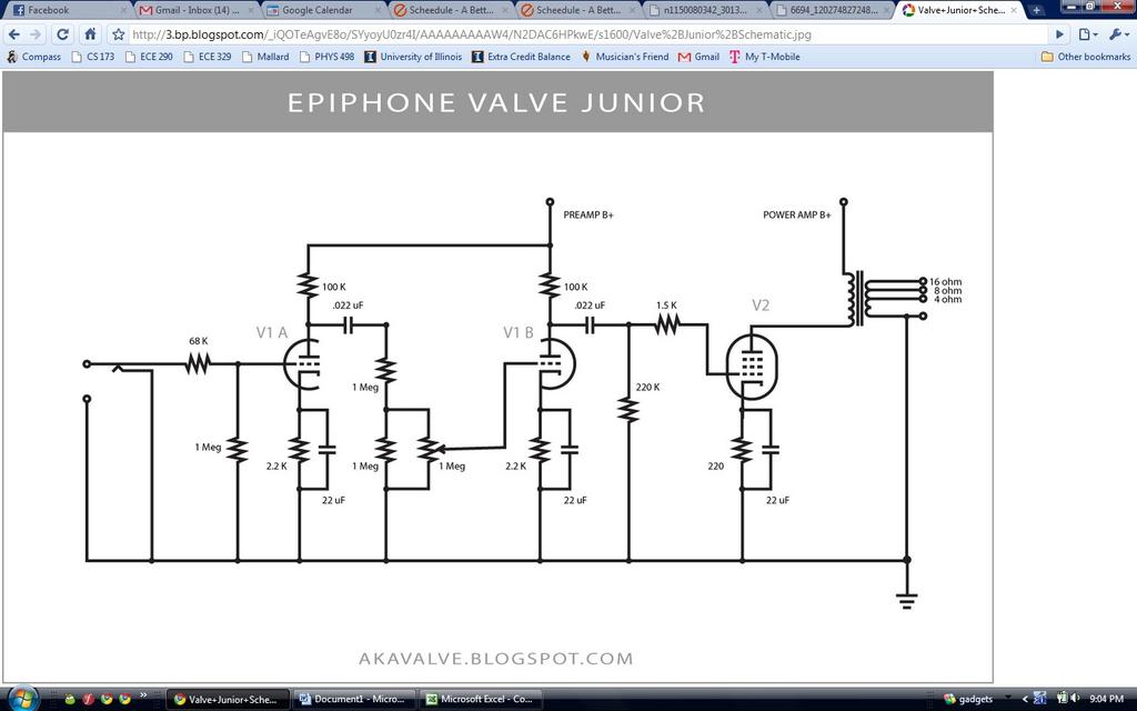
4
5 Modifications made 1. Replacement of the output transformer 2. Replacement of audio potentiometer (volume pot) 3. Fixing of the voltage divider between R2 and R1 4. Dropping of R2 from 68K to 34K 5. Addition of grid stopper resistor 6. Addition of bright switch 7. Addition of fat switch 8. Addition of preamp tube shield (See next page for post modification schematic)
6
 while speakers are high current, low voltage devices (low impedance devices).")
7 1. Replacement of the output transformer The first modification made to the amplifier was the replacement of the stock output transformer with a Hammond DSE 125 output transformer. The way output transformers work is as follows: Tubes are high voltage, low current devices (high impedance devices) while speakers are high current, low voltage devices (low impedance devices). The output transformer is responsible for transforming the high impedance of the tube to match the lower impedance of the speaker. Transformers are essentially pairs of electrically insulated windings that are magnetically coupled to each other. It turns out that the ratio of the number of primary windings to the number of secondary windings equals the ratio of the input AC voltage to the output AC voltage, the ratio of the output current to the input current, and (by Ohm's law) the square root of the ratio of the resistance of the secondary to the resistance of the primary. Power in = Power out V in * I in = V out * I out V in / V out = I out / I in = number of primary turns / number of secondary turns = n n^2 = R secondary / R primary The impedance matching can therefore be made by determining the proper ratio of primary turns to secondary turns. The reason for replacing the stock output transformer with the higher quality Hammond DSE 125 output transformer was because the Hammond can handle a larger amount of power, so any breakup heard from the amplifier would be 100% from the tubes breaking up, as opposed to the output transformer. It should be noted that the drilling of an extra hole in the chassis is necessary to make this modification as the Hammond is slightly wider than the stock transformer. It should also be noted that the coloring of the wires to and from the stock transformer ARE DIFFERENT than those on the Hammond. See the following page for the diagrams of both.
8
 output")
9 The new (left) and old (right) output transformers:


10 2. Replacement of the audio potentiometer The next modification made to the amplifier was to replace the existing 1 megaohm audio potentiometer with a higher quality, PEC 1 megaohm audio pot. The way the potentiometer works is as follows: The potentiometer is essentially a variable resistor. It has three terminals and a wiper. The outer most terminals are connected by a carbon trace ring. When used as a volume control (as it is in this case), one of these terminals is to be connected to ground and the other to the input. The wiper is connected to the middle terminal as well as the carbon trace. Provided the proper terminals are chosen for the input and ground, sweeping the wiper clockwise will produce an output that becomes less and less attenuated, until the wiper is completely clockwise. In that case, the output will be directly connected to the input, and no attenuation will occur. Sweeping the wiper counterclockwise will produce an output that becomes more and more attenuated until the wiper is completely counterclockwise. In that case, the output will be directly connected to ground, and (in theory) no signal will be passed through. The way this happens inside of the potentiometer is directly related to the idea that it is a variable resistor. When the wiper is swept fully clockwise, the input and output are literally connected. As it is swept counterclockwise, a greater and greater amount of carbon trace exists between the input and the output, and the resistance increases, causing an attenuated input to be passed. Once the wiper is swept fully counterclockwise, the output is directly connected to ground. The reason for replacing the potentiometer with a higher quality one is to be sure that the pot can handle the power going through it along with the concern that the carbon trace in the original, poor quality pot can burn up and the pot could be easily destroyed. See the following page for the diagram of the potentiometer.
11
12 3. Fixing the voltage divider As can be seen in the pre modification schematic, the 68K and 1M resistors early on in the signal path (R1 and R2) look like: which can be redrawn as: which is a voltage divider. With this in place, the input signal will be cut down to 1*10^6/(1*10^6 + 68*10^3) = 93.6% of its initial value. This isn't an enormous drop, but in a situation where you want to throw away as little of your signal as possible, it is in no way desirable. The third modification made to the amplifier was to fix this design flaw. The wiring was changed so that this area now looks like:
13 4. Dropping the resistance of R2 One of the first resistors in the signal path is R2, which, stock, is 64 kilo ohms. As can be seen by Ohms law, when this resistance is lowered, the voltage drop across it will decrease. The resistance can effectively be dropped to zero so that no voltage drop occurs. This presents the risk of introducing a large amount of high frequency signals into the signal path (such as TV or radio waves). To prevent this, but still attain a smaller voltage drop to keep a hotter input signal, the resistance of R2 was decreased to half of its original value. Instead of physically replacing the resistor, a resistor of equal value was soldered in parallel with it. Since the effective resistance of two resistors in parallel is: R1R2/(R1+R2), the effective resistance of the two 64 kilo ohm resistors is: (64000*64000)/( ) = 32 kilo ohms (half the original value). 64K 64K = 32K

14 The fixed voltage divider and the doubling of the 64K resistor:

15 5. Addition of grid stopper resistor As mentioned earlier, there exists the possibility of high frequency signals being introduced to the signal path. This most often occurs in the preamp stage of the amplifier. To prevent these high frequencies from getting amplified and sent to the power amp section of the amplifier, a 10K resistor was placed before the second triode of the preamp tube in order to block them out.
 is strapped in parallel over the volume")
16 6. Addition of bright switch The next modification made to the amplifier was the addition of a bright switch. The way the bright switch works is as follows: When the bright switch is engaged, a capacitor (in this case, a 120 picofarad silver mica capacitor) is strapped in parallel over the volume potentiometer. The expression for the impedance of a capacitor is: Zcap = 1/(jѡC), where ѡ is the frequency in radians/sec and C is the capacitance in farads. This makes it clear that as the frequency increases, the impedance decreases. Therefore, the capacitor will allow high frequencies which would have otherwise been blocked out by the 1Meg volume pot to pass through. This will make the overall sound brighter, as there will be a larger high frequency content than before. When the bright switch is disengaged, the amplifier acts normally (as if the capacitor is not there). In order to maintain a healthy signal and prevent unwanted noise from getting into the signal path, this switch was wired with shielded coaxial cable. The bright switch is wired using a DPDT On/Off Mini Toggle. Note: extra holes must be drilled for the toggles. 120 pf See the following pages for the wiring schematic of the bright switch and the DPDT On/Off Toggle
17
18

19 The bright switch
, a 10 mega ohm resistor is")
20 7. Addition of a fat switch The next modification made to the amplifier was the addition of a fat switch. The way the fat switch works is as follows: When the fat switch is engaged (in this situation, when the switch is in the off position, the fat switch is actually engaged), a 10 mega ohm resistor is placed in series with the 22 microfarad capacitor underneath the second triode of the preamp tube. This essentially takes the capacitor completely out of the circuit, and holds the minimum of the AC voltage across the tube to a constant, which results in a doubling of the gain of achieved by the tube. When the fat switch is disengaged, the amplifier acts normally (as if the resistor is not there). In order to maintain a healthy signal and prevent unwanted noise from getting into the signal path, this switch was also wired with shielded coaxial cable. The fat switch is also wired using a DPDT On/Off Mini Toggle. 10 Megaohm See the following page for the schematic of the fat switch.
21

22 The fat switch

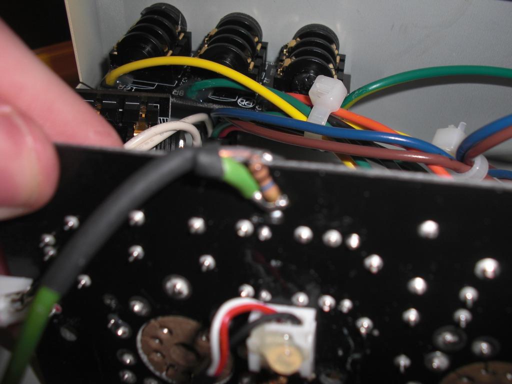
23 The fat switch and the DPDT mini toggles

24 8. Addition of preamp tube shield The final modification made to the amplifier was the addition of a preamp tube shield. It was put in out of necessity due to oscillations that occurred after all the other modifications were put in. The shield was put in right above the preamp tube, the area which appeared to be the source of the oscillations. Its purpose is to ground those oscillations before they can get into the signal path.
25 Measurements Taken VAC Line = VAC RMS VAC Main Secondary = VAC RMS VAC Heater = 6.77 VAC RMS VB+ = 358 VDC VA = VDC VB = VEL 84 Screen = 318 VDC VC = VDC DC Voltages: Grid Cathode Plate Current (I) Power Dissipated V1A 0 VDC VDC VDC.976 ma.1926 W V1B 0 VDC VDC VDC ma.1988 W V2.01 VDC 9.73 VDC VDC ma W *Power Dissipated=(VPlate VCathode)*I *I = V/R where R under V1 is 1.5K and R under V2 is 220 ohms AC Voltages: Grid Cathode Plate Voltage Gain V1A 70.7mVRMS 0 VRMS 3.39VRMS V1B Fat Switch Off 43.8 mvrms 24.2 mvrms VRMS 24.9 V1B Fat Switch On 43.8 mvrms 0 VRMS VRMS V2 Fat Switch Off VRMS 81.7 mvrms 99.9 VRMS V2 Fat Switch On VRMS 168.4mVRMS 194.7VRMS *Voltage Gain = Vplate/VGrid
26
27
28
29
30 Sources Jones, Morgan. Valve Amplifiers. 3rd ed. Oxford: Newnes, Print. 1, Aug. "How Transformers Work." Electrical Construction and Maintenance Power Quality, National Electric Code, Construction, V/D/V, Ops, Equipment Rental Industry Resource. Web. 13 May < Steve Errede
Jason Stull. Physics 498 (Physics of Music) Valve Junior Modification 5/13/2010
 Valve Junior Modification 5/13/2010") Jason Stull Physics 498 (Physics of Music) Valve Junior Modification 5/13/2010 1 Introduction My original idea for a class project was to build a tube guitar amplifier. I have wanted a tube amp for some
Jason Stull Physics 498 (Physics of Music) Valve Junior Modification 5/13/2010 1 Introduction My original idea for a class project was to build a tube guitar amplifier. I have wanted a tube amp for some
Tweed Champ 5F1 (assembling the board)
") Tweed Champ 5F1 (assembling the board) The Beginning of Great Tone - In 1958, the Fender Champ with it's 8 speaker and 5 watts of power became the mother of great tone. By combining the new 12AX7 with
Tweed Champ 5F1 (assembling the board) The Beginning of Great Tone - In 1958, the Fender Champ with it's 8 speaker and 5 watts of power became the mother of great tone. By combining the new 12AX7 with
Ear+ Purist HD. Ear+ HD II High Definition Stereo Headphone Amplifier
 Ear+ Purist HD Ear+ HD II High Definition Stereo Headphone Amplifier Users' Manual Rev Mar 8/19 Mapletree Audio Design R. R. 1, Seeley's Bay, Ontario, Canada, K0H 2N0 (613) 387-3830 www.mapletreeaudio.com
Ear+ Purist HD. Ear+ HD High Definition Stereo Headphone Amplifier
 Ear Purist HD Ear HD High Definition Stereo Headphone Amplifier 2AX7 Users' Manual ev Oct. 7/3 Mapletree Audio Design loyd Peppard.., Seeley's Bay, Ontario, Canada, K0H 2N0 (63) 387-3830 www.mapletreeaudio.com
1. Summary. 15/08/2009 Philips Valve Amplifier Type LBH1015/01 Page 1 of 7. Valve PA Amplifier. Philips label Model Code LBH1015/01 Serial No 1080
 15/08/2009 Philips Valve Amplifier Type LBH1015/01 Page 1 of 7 1. Summary Valve PA Amplifier. Philips label Model Code LBH1015/01 Serial No 1080 Two input, mono 60W amplifier with tone control and 50V/70V/100V
1.1 Original Amplifier Professional construction well made. No markings. Based on R&H Feb Watt Amplifier.
 4/03/2018 Australian 5W Combo Page 1 of 6 1. Summary Combo 5W Valve Amplifier and 8 Rola speaker. Unknown maker., Dec 2017. 1.1 Original Amplifier Professional construction well made. No markings. Based
AWA W valve amplifier. S.N. Z177. Gratis Stephen (Brucer) Nov, 2014
 Nov, 2014") 9/01/015 AWA PA87 AMPLIFIER Page 1 of 8 1. Summary AWA 87 0W valve amplifier. S.N. Z177. Gratis Stephen (Brucer) Nov, 014 MIC-Phono input channel PA amplifier. 1AX7 mic preamp. 1AX7 mixer with feedback
9/01/015 AWA PA87 AMPLIFIER Page 1 of 8 1. Summary AWA 87 0W valve amplifier. S.N. Z177. Gratis Stephen (Brucer) Nov, 014 MIC-Phono input channel PA amplifier. 1AX7 mic preamp. 1AX7 mixer with feedback
Fixing/Rebuilding a Rickenbacker M-10
 Fixing/Rebuilding a Rickenbacker M-10 James Milsk Physics 498 May 9, 2005 Professor Errede 1 My uncle had given me a 1950 s-era Rickenbacker M-10 guitar amplifier to fix because he tried plugging a guitar
Electrical Fundamentals and Basic Components Chapters T2, T3, G4
 Electrical Fundamentals and Basic Components Chapters T2, T3, G4 Some Basic Math, Electrical Fundamentals, AC Power, The Basics of Basic Components, A Little More Component Detail, Reactance and Impedance
Mapletree Audio Design SR70A Special Red Driver Module for Dynaco ST-70
 Mapletree Audio Design S70A Special ed Driver Module for Dynaco ST-70 Installation instructions ev. Jan. 9/ The Special ed S70A driver module is a drop in replacement for the original driver board of the
A 75-Watt Transmitter for 3 Bands Simplified Shielding and Filtering for TVI BY DONALD H. MIX, W1TS ARRL Handbook 1953 and QST, October 1951
 A 75-Watt Transmitter for 3 Bands Simplified Shielding and Filtering for TVI BY DONALD H. MIX, W1TS ARRL Handbook 1953 and QST, October 1951 The transmitter shown in the photographs is a 3-stage 75-watt
Physics of Music Projects Final Report
 Physics of Music Projects Final Report John P Alsterda Prof. Steven Errede Physics 498 POM May 15, 2009 1 Abstract The following projects were completed in the spring of 2009 to investigate the physics
Radio Station Setup and Electrical Principles
 Radio Station Setup and Electrical Principles Covers sections: T4A-T5D Seth Price, N3MRA February 20, 2016 Outline 4.1 Station Setup 4.2 Operating Controls 4.3 Electronic Principles 4.4 Ohm s Law 4.5 Power
Archivist s Note: The plans are mislabeled and are actually for a tube-driven tremolo. See letter to the editor at the end of this document.
 Archivist s Note: The plans are mislabeled and are actually for a tube-driven tremolo. See letter to the editor at the end of this document. Build Your Own Vibrato Make like Elvis with an "electronic"
Williamson Amplifier & matching Control Unit Preamplifier. $202 ebay Oct 2009 Australian manufacturer unknown.
 30/06/2011 WILLIAMSON AMPLIFIER & PREAMP Page 1 of 11 1. Summary Williamson Amplifier & matching Control Unit Preamplifier. $202 ebay Oct 2009 Australian manufacturer unknown. 1.1 Original Main Amplifier
TRACE ELLIOT SERVICE MANUAL NO. SM00025 ISSUE 1
 TRACE ELLIOT SERVICE MANUAL NO. SM00025 ISSUE 1 Date: January 6, 1997 Product Code : T3455/3456 Model No : Velocette 12R / Alnico Technical File No : TE00025 Issued by: Trace Elliot Limited. Blackwater
Ultra 4B SE Special Edition. Stereo Phono/Line Preamplifier
 Modular Series Ultra B SE Special Edition Stereo Phono/Line Preamplifier User s Manual Phono Line Line Balance Volume Mapletree Audio Design Ultra B SE Stereo Preamplifier Rev. Feb. / Mapletree Audio Design
Modification of a Tube Amplifier
 Modification of a Tube Amplifier Michael Schubert Physics 406 Spring 2013 5/10/2013 Introduction The tube amplifier has been a mainstay of rock and roll music since its beginning. Even now, despite being
THD FLEXI-50 INSTRUCTION MANUAL 1
 THD Flexi-50 Instruction Manual Thank you for your purchase of the THD Flexi-50 amplifier! The Flexi-50 is a precision hand-built 50-watt Class-AB amplifier with foot-switchable overdrive/boost, footswitchable
fuzzbox If you are asked to imagine the sound soldering your way to distortion how to make a diy by rob cruickshank photography by adam coish
 diy how to make a fuzzbox soldering your way to distortion by rob cruickshank photography by adam coish If you are asked to imagine the sound of an electric guitar, there s a good chance that the sound
Operation and Maintenance Manual
 WeiKedz 0-30V 2mA-3A Adjustable DC Regulated Power Supply DIY Kit Operation and Maintenance Manual The WeiKedz Adjustable DC Regulated Power Supply provides continuously variable output voltage between
PHYS 406. Spring Final Report. Connor Gooding 05/16/2014 Prof. Steven Errede
 PHYS 406 Spring 2014 Final Report Refurbishing a 1965 National Westwood N6422TR Amplifier Introduction/History Connor Gooding 05/16/2014 Prof. Steven Errede This 1965 National Westwood N6422TR is a combo
DUAL RECTIFIER TRIODE. Rev B 1 THE AX84 AMP (REV 10)- THEORY OF OPERATION
- THEORY OF OPERATION") THE AX84 AMP (REV 10)- THEORY OF OPERATION Let's take a walk through the inner workings of this amp. Along the way, I will be including some math and electronic theory. To fully understand how a guitar
THE AX84 AMP (REV 10)- THEORY OF OPERATION Let's take a walk through the inner workings of this amp. Along the way, I will be including some math and electronic theory. To fully understand how a guitar
MASTR II AUXILIARY RECEIVER 19D417546G7 & G8 & ANTENNA MATCHING UNITS 19C321150G1-G2. Maintenance Manual LBI-30766L. Mobile Communications
 L Mobile Communications MASTR II AUXILIARY RECEIVER 19D417546G7 & G8 & ANTENNA MATCHING UNITS 19C321150G1-G2 Printed in U.S.A Maintenance Manual TABLE OF CONTENTS Page SPECIFICATIONS.....................................................
Classic Valve Design
 7C Phono Stage for the Dynaco PAS2, PAS3, PAS3X Classic Valve Design Classic Valve Design assumes no responsibility for circuit or user damage from the use or misuse of these boards or any other product.
CALRAD 25 series - potentiometers
 25 series - potentiometers audio /linear SUB-MINIATURE VOLUME CONTROLS Linear taper, extremely smooth for quiet operation. 1 2" dia. fits into 1 4" hole. Shaft 3 16" dia. Thread length 7 32", shaft length
Modifying The Heath HA-14 For 6 Meters Greg Chartrand - W7MY 4/22/07
 Introduction The Heathkit HA-14 was one of the few electron tube linear amplifiers intended for mobile use but few were purchased with the 12 volt mobile power supply. Most hams bought the HA-14 for base
INSTRUCTIONS FOR ASSEMBLY AND OPERATION
 diytube stereo 0 driver board INSTRUCTIONS FOR ASSEMBLY AND OPERATION Price $0.00 Important Note: The phase is swapped on the diytube ST0 from the orginal design. Be sure to hook up the drive lines (at
2π LC. = (2π) 2 4/30/2012. General Class Element 3 Course Presentation X C. Electrical Principles. ElectriElectrical Principlesinciples F 2 =
 2 4/30/2012. General Class Element 3 Course Presentation X C. Electrical Principles. ElectriElectrical Principlesinciples F 2 =") General Class Element 3 Course Presentation ti ELEMENT 3 SUB ELEMENTS General Licensing Class Subelement G5 3 Exam Questions, 3 Groups G1 Commission s Rules G2 Operating Procedures G3 Radio Wave Propagation
General Class Element 3 Course Presentation ti ELEMENT 3 SUB ELEMENTS General Licensing Class Subelement G5 3 Exam Questions, 3 Groups G1 Commission s Rules G2 Operating Procedures G3 Radio Wave Propagation
A 100-Watt Transmitter Using a Pair of VT1625s
 12/16/2007 6:00 PM VT1625 100 Watt Transmitter A 100-Watt Transmitter Using a Pair of VT1625s FIG. 10.6 A 100-watt transmitter for five bands, using salvaged TV power transformer and surplus 1625 amplifier
You Just Brought an Old Radio Home: Now What Do You Do?
 You Just Brought an Old Radio Home: Now What Do You Do? Raymond Cady goldenageradiorestoration.com Whether you are just beginning to collect antique radios or you have been at it for a number of years,
JCM W GUITAR AMPLIFIER. User s Manual
 JCM 800 2203 100W GUITAR AMPLIFIER User s Manual 1 Thank you for the purchase of your Ceriatone guitar amplifier! Here, we hope to explain how best to use your new amp. Table of Contents 1) About the 2203..
TABLE OF CONTENTS. Page 1 of 8. Copyright MasterTone Amplifiers 2008 amplifiers.co.uk
 TABLE OF CONTENTS Why modify the Valve Junior?... 2 About the modifications... 2 What the modifications do...3 Voice Switch...3 Gain Switch...3 Volume...3 Master Volume...3 Power Scale...4 Standby Switch...4
Classic Valve Design
 DynaMull Driver Board for the Dynaco ST-70 Classic Valve Design Classic Valve Design assumes no responsibility for circuit or user damage from the use or misuse of these boards or any other product. We
DynaMutt Driver Board for the Dynaco ST-70
 DynaMutt Driver Board for the Dynaco ST-70 Octal Version Design by: Classic Valve Design Classic Valve Design assumes no responsibility for circuit or user damage from the use or misuse of these boards
Professional Equalizer-Preamp Suitable for Home Use
 A combined Professional Equalizer-Preamp Suitable for Home Use KENNETH W. BETSH* Designed originally for broadcast-station use, this preamplifier can be adapted to any installation where it would be desirable
Manual Version July 2007
 Manual Version 1.2 - July 2007 Page 1 Table of Contents Section1: M3 Phono Board Build...3 Phono Board Parts List...3 Preparation...4 Fitting the Valve Bases...6 Installing the Resistors...7 Starting the
Lab Equipment EECS 311 Fall 2009
 Lab Equipment EECS 311 Fall 2009 Contents Lab Equipment Overview pg. 1 Lab Components.. pg. 4 Probe Compensation... pg. 8 Finite Instrumentation Impedance. pg.10 Simulation Tools..... pg. 10 1 - Laboratory
Preface... xv Acknowledgments... xix. Chapter 1 An Overview of Vacuum Tube Audio Applications... 1
 Contents Preface... xv Acknowledgments... xix Chapter 1 An Overview of Vacuum Tube Audio Applications... 1 The Evolution of Analog Audio... 1 Technology Waves... 3 Tube vs. Solid State.................................................
JCM W GUITAR AMPLIFIER. User s Manual
 JCM 800 2204 50W GUITAR AMPLIFIER User s Manual 1 Thank you for the purchase of your Ceriatone guitar amplifier! Here, we hope to explain how best to use your new amp. Table of Contents 1) About the 2204..
The following examples explore some of the possible uses of these preamps.
 The series preamplifiers are designed to improve the performance of electric instruments by increasing the signal level, modifying tonal quality with a wide range of options and decreasing the treble losses
The Ins and Outs of Audio Transformers. How to Choose them and How to Use them
 The Ins and Outs of Audio Transformers How to Choose them and How to Use them Steve Hogan Product Development Engineer, Jensen Transformers 1983 1989 Designed new products and provided application assistance
Triplett 3444A Power Supply Modification Notes
 Triplett 3444A Power Supply Modification Notes The Triplett 3444A is a superb Tube Test/Analyzer. Mutual Conductance is measured by inserting a small known AC signal on the Grid, and measuring the AC Plate
CALRAD MINIATURE MULTI-CLICK DUAL CONTROLS 40 STEP P.C. MOUNT 11
 25 Series - Potentiometers Audio & Linear SUB-MINIATURE VOLUME CONTROLS Linear taper, extremely smooth for quiet operation. 1 /2" dia. fits into 1 /4 hole. Shaft 3 /16" dia. Thread length 7 /32", shaft
The Electro-Magnetic Spectrum
 The Electro-Magnetic Spectrum Part Three In This Issue: All about Tubes How a diode rectifier works How a triode amplifier works How the mixer in your receiver works Dear Friends: For quite some time I
Power Supply Board. by Classic Valve Design for the Dynaco Mark-III with failsafe bias and balance
 Power Supply Board by Classic Valve Design for the Dynaco Mark-III with failsafe bias and balance Classic Valve Design assumes no responsibility for circuit or user damage from the use or misuse of these
IPR LA-3 KIT last update 15 march 06
 IPR LA-3 KIT last update 15 march 06 PART-2: Audio Circuitry CIRCUIT BOARD LAYOUT: Power and Ground Distribution Now that your power supply is functional, it s time to think about how that power will be
DIY Tube Stereo 70 Board - TubeZone Assembled -Instructions - Page 1
 DIY Tube Stereo 70 Board - TubeZone Assembled -Instructions - Page 1 Board and portions of manual, (c) 2006 Shannon Parks & DIYtube.com. Version specific instructions (c) 2006 Ned Carlson and Tubezone.net
1. Summary. 1/08/2016 Steanes 976B Amplifier & Speaker Combo Page 1 of 8. Steanes Model 976B & Speaker Combo. Serial No
 /08/06 Steanes 96 Amplifier & Speaker Combo Page of 8. Summary Steanes Model 96 & Speaker Combo. Serial No. 66. AX microphone gain stage with volume pot to AX mixer stage, with PU input through volume
SPECIFICATIONS: Subcarrier Frequency 5.5MHz adjustable, FM Modulated +/- 50KHz. 2nd 11MHz >40dB down from 5.5MHz
 Mini-kits AUDIO / SUBCARRIER KIT EME75 Version4 SPECIFICATIONS: Subcarrier Frequency 5.5MHz adjustable, FM Modulated +/- 50KHz Subcarrier Output 1.5v p-p Output @ 5.5MHz DESCRIPTION & FEATURES: The Notes
To make this design more accessible, is offering a limited number of kits for this design including VFETs, pc boards, and hardware.
 The DIY Sony VFET by Nelson Pass This is an addendum to the Sony SIT AMP part 2 article is the second of a series presenting Do-It-Yourself audio power amplifiers using Static Induction Transistors (SITs),
25V. Left Output Transformer Connection Right Output Transformer Connection J4 R9 100K, 1W R10 100K, 1W V V R12 220K R11 220K V1 12SL7
 V Left Output Transformer onnection Right Output Transformer onnection J J R9 00K, W R0 00K, W V 66 p p V 66 R K g g.uf, 00V.uF, 00V R K h h R 0K R 0K h V SL a a'' h.6v J Right Input R K R K + 0uF V R
1. Each group will get one aluminum BUD chassis (also called BUD box ).
.") I. INTRODUCTION At the beginning of this lab, each group will be given an aluminum box called a BUD box or a BUD chassis. ( BUD is just the name of a company that makes these boxes.) Each BUD box has a
I. INTRODUCTION At the beginning of this lab, each group will be given an aluminum box called a BUD box or a BUD chassis. ( BUD is just the name of a company that makes these boxes.) Each BUD box has a
Basic operational amplifier circuits In this lab exercise, we look at a variety of op-amp circuits. Note that this is a two-period lab.
 Basic operational amplifier circuits In this lab exercise, we look at a variety of op-amp circuits. Note that this is a two-period lab. Prior to Lab 1. If it has been awhile since you last used the lab
Dynaco ST-70 Input Board
 A u dio L ab s Sheldon Stokes 11811 Island Cove Dr. Fort Wayne, IN 46845 stokes@spinn.net http://www.quadesl.com Dynaco ST-70 Input Board 1 Introduction This board is a drop-in replacement for the original
DC Power Supply Design
 Sopczynski 1 John Sopczynski EE 310 Section 4 DC Power Supply Design Introduction The goal of this experiment was to design a DC power supply. Our team would be receiving 120 Vrms oscillating at 60 Hz
Copyright 2016, R. Eckweiler & OCARC, Inc. Page 1 of 7
 Heathkit of the Month: by Bob Eckweiler, AF6C ELECTRONIC TEST EQUIPMENT Heathkit IM-38 AC Vacuum Tube Voltmeter (VTVM). Introduction: Back in March of 2013 Heathkit of the Month #47 discussed the Heathkit
C22 Vacuum Tube Preamplifier Complete User Manual Analog Metric
 C22 Vacuum Tube Preamplifier Complete User Manual Analog Metric sales@analogmetric.com Copyright 2009 All Rights Reserved [C22 VACUUM TUBE PREAMPLIFIER COMPLETE USER Page 2 INTRODUCTION The circuit design
Elecraft EC1 Design Contest Entry
 Elecraft EC1 Design Contest Entry The following is an Elecraft EC1 design contest entry from Joe Loritz, N9ZIA. Design Overview This design is a low cost, easy to homebrew, 100-900 MHz antenna analyzer.
D. Gillespie Designs. SCA-35 Capacitor Board. Installation Manual. D. Gillespie Designs with EFB TM
 D. Gillespie Designs SCA-5 Capacitor Board with EFB TM Installation Manual D. Gillespie Designs www.tronola.com Thank you for choosing our SCA-5 Capacitor Board with *EFB. We feel it is the single most
MASTR II BASE STATION MHz RECEIVER IF/AUDIO/SQUELCH & RF ASSEMBLY (25 khz/12.5 khz CHANNEL SPACING) Maintenance Manual LBI-38506A
 Maintenance Manual LBI-38506A") A Mobile Communications MASTR II BASE STATION 806-824 MHz RECEIVER IF/AUDIO/SQUELCH & RF ASSEMBLY (25 khz/12.5 khz CHANNEL SPACING) TABLE OF CONTENTS RF ASSEMBLY, MIXER AND IF FILTER BOARD...... LBI-30482
A Mobile Communications MASTR II BASE STATION 806-824 MHz RECEIVER IF/AUDIO/SQUELCH & RF ASSEMBLY (25 khz/12.5 khz CHANNEL SPACING) TABLE OF CONTENTS RF ASSEMBLY, MIXER AND IF FILTER BOARD...... LBI-30482
MFJ-249B HF/VHF SWR ANALYZER
 TABLE OF CONTENTS MFJ-249B... 2 Introduction... 2 Powering The MFJ-249B... 3 Battery Installation... 3 Alkaline Batteries... 3 NiCd Batteries... 4 Power Saving Mode... 4 Operation Of The MFJ-249B...5 SWR
ELECTRICAL Cathode... coated unipotential Heater Voltage Volts Heater Current
 Power Pentode The E34LS is a power pentode designed especially for high fidelity audio systems. It has a plate dissipation of 30 watts and delivers high power without drawing control-grid current. The
Coleman Bias Regulator V1
 Coleman Bias Regulator V1 1. General application. 1.1. The Bias Regulator is a low current (
Classic Valve Design
 PAS Purist Line Amplifier Designed by Norman Koren (aka PAS-K Line) for the Dynaco PAS2, PAS3, PAS3X Classic Valve Design Classic Valve Design assumes no responsibility for circuit or user damage from
Circuit and wiring connections as follows:
 Fault Indication via TTL compatible open collector output (can be used for additional protection circuitry or for our upcoming electronic choke PSU PCB) multiple mounting holes for easy mounting Can be
University of Jordan School of Engineering Electrical Engineering Department. EE 204 Electrical Engineering Lab
 University of Jordan School of Engineering Electrical Engineering Department EE 204 Electrical Engineering Lab EXPERIMENT 1 MEASUREMENT DEVICES Prepared by: Prof. Mohammed Hawa EXPERIMENT 1 MEASUREMENT
New Life for the AM6154 and AM6155 John, W1AN 29 July, 2014
 New Life for the AM6154 and AM6155 John, W1AN 29 July, 2014 There are numerous sources for conversion information and modifications that have been shared over the years for the FAA AM6154 and AM6155 amplifiers
Mini Block Ultra Linear Class A Push-Pull Valve Power Amplifier
 Mini Block Ultra Linear Class A Push-Pull Valve Power Amplifier Precaution: This project uses potentially lethal voltages and should not be undertaken by anyone who is not familiar with working with such
FUNCTION GENERATOR KIT
 FUNCTION GENERATOR KIT MODEL FG-500K Assembly and Instruction Manual Elenco Electronics, Inc. Copyright 2005 by Elenco Electronics, Inc. All rights reserved. Revised 2005 REV-B 753069 No part of this book
Heathkit of the Month #64 - VC-3 Voltage Calibrator
 Heathkit of the Month: by Bob Eckweiler, AF6C Heathkit VC-3 Voltage Calibrator. Introduction: The August 2013 Heathkit of the Month (#51) covered the IG-4505 Deluxe Oscilloscope Calibrator. It also briefly
Basic Electrical Training
 Basic Electrical Training Electricians Tools Explain how various hand tools are used by an electrician Discuss the safe use of hand tools and power tools Perform basic calculations and measurement conversions
Basic Electronics Prof. T.S. Natarajan Department of Physics Indian Institute of Technology, Madras
 Basic Electronics Prof. T.S. Natarajan Department of Physics Indian Institute of Technology, Madras Lecture 39 Silicon Controlled Rectifier (SCR) (Construction, characteristics (Dc & Ac), Applications,
VCE VET ELECTROTECHNOLOGY
 Victorian Certificate of Education 2010 SUPERVISOR TO ATTACH PROCESSING LABEL HERE STUDENT NUMBER Letter Figures Words VCE VET ELECTROTECHNOLOGY Written examination Thursday 4 November 2010 Reading time:
Vacuum Tube Amplifier
 Vacuum Tube Amplifier ECE 445 Design Document Qichen Jin and Bingqian Ye Group 1 TA: Zhen Qin Table of Contents 1 Introduction. 1 1.1 Objective.. 1 1.2 Background. 1 1.3 High-level requirements.. 2 2 Design..
2. Solve this binary equation. Answer in a decimal number form = A. 42 B. 54 C. 15 D
 Electronics Practice Test By David Scott, Manfred Brancard and Gary Troutman 1. A few capacitors are in parallel. Calculate the total capacitance. The capacitor values are 1uF, 2uF, 3uF, and 4uF. The total
Build an All-Tube Fuzz/Wah Pedal
 Build an All-Tube Fuzz/Wah Pedal by Eric Barbour and Peter Belov In spite of more than 30 years of development and marketing, to this day all commercial guitar "wah" pedals have been solid- state and have
VASE PA100, S.N. 116/100/ T. 6 microphone input channel PA amplifier. $ ebay Jan 2009
 19/03/2009 VASE P.A.100 AMPLIFIER Page 1 of 9 1. Summary VASE PA100, S.N. 116/100/ T. 6 microphone input channel PA amplifier. $121.40 ebay Jan 2009 Each microphone channel with BC109 input, followed by
Technician Licensing Class T6
 Technician Licensing Class T6 Amateur Radio Course Monroe EMS Building Monroe, Utah January 11/18, 2014 January 22, 2014 Testing Session Valid dates: July 1, 2010 June 30, 2014 Amateur Radio Technician
THE ZEN TRIODE EXPIREMENTERS AMPLIFIER KIT MODEL SE84CDIYMONO
 THE ZEN TRIODE EXPIREMENTERS AMPLIFIER KIT MODEL SE84CDIYMONO ASSEMBLY INSTRUCTIONS 2008 The circuit board has been designed to be used in 2 ways; A) Mounted on stand-offs to a piece of wood and B) Mounted
Contents. 1. Essential Electronics 1. Preface Acknowledgements
 Contents Preface Acknowledgements ix xi 1. Essential Electronics 1 1.1: Current 2 1.2: Voltage 5 1.3: Power 6 1.4: Signals and Averages 7 1.4.1: Mean Average 7 1.4.2: Rectified Average 8 1.4.3: RMS Average
How The Transmitter Works
 Mike Bray, K8DDB Refer to the schematic of the transmitter on page 7 of the manual. The crystal-controlled oscillator, V generates a small amount of r.f. power which is used to drive the amplifier, V2.
Electrifying an Acoustical Guitar. Cody Jones Final Project Report Physics
 Electrifying an Acoustical Guitar Cody Jones Final Project Report Physics 406 5-11-12 1 Introduction: While attempting to find a suitable project for the class, I came upon the idea of an electric guitar.
Tube Guitar Amplifier Oscilloscope Diagnosis
 OVERVIEW Caveat Proceed at your own peril! The methods and procedures I outline in this document have worked well for me. However, they are the results of my personal experiences. I have no doubt a properly
Basic Electronics. Chapter 2, 3A (test T5, T6) Basic Electrical Principles and the Functions of Components. PHYS 401 Physics of Ham Radio
 Basic Electrical Principles and the Functions of Components. PHYS 401 Physics of Ham Radio") Basic Electronics Chapter 2, 3A (test T5, T6) Basic Electrical Principles and the Functions of Components Figures in this course book are reproduced with the permission of the American Radio Relay League.
Basic Electronics Chapter 2, 3A (test T5, T6) Basic Electrical Principles and the Functions of Components Figures in this course book are reproduced with the permission of the American Radio Relay League.
BMC052. Chordizer Last updated
 BMC052. Chordizer Last updated 8-27-2017 If you have any questions, or need help trouble shooting, please e-mail Michael@Bartonmusicalcircuits.com I Overview/Controls/Inputs/Outputs II Schematic III Construction
Assembly Manual V1R2B-Rev1.0D
 Assembly Manual V1R2B-Rev1.0D for 4 State QRP MagicBox - Solid State Transmit/Receive System Designed by: Jim Kortge, K8IQY Copyright 2009-2012 - All rights reserved This system is the result of some brainstorming
V6.2 SoftRock Lite Builder s Notes. November 17, 2006
 V6.2 SoftRock Lite Builder s Notes November 17, 2006 Be sure to use a grounded tip soldering iron in building the v6.2 SoftRock circuit board. The soldering iron needs to have a small tip, (0.05-0.1 inch
POWER SUPPLY MODEL XP-720. Instruction Manual ELENCO
 POWER SUPPLY MODEL XP-720 Instruction Manual ELENCO Copyright 2016, 1997 by ELENCO Electronics, Inc. All rights reserved. Revised 2016 REV-H 753270 No part of this book shall be reproduced by any means;
MZ2 HEADPHONE AMPLIFIER, PREAMP, & STEREO AMPLIFIER USER GUIDE
 MZ2 HEADPHONE AMPLIFIER, PREAMP, & STEREO AMPLIFIER USER GUIDE Linear Tube Audio Takoma Park, MD, USA WARNING: For safety, the cover of this amplifier should be secured at all times. DC voltages as high
THÖRESS F2A11 Stereo Integrated Amplifier...
 THÖRESS F2A11 Stereo Integrated Amplifier INSTRUCTION MANUAL Thank you for purchasing the THÖRESS F2A11 Stereo Integrated Amplifier. This truly unique tube amplifier offers the music lover the possibility
T6A4. Electrical components; fixed and variable resistors, capacitors, and inductors; fuses, switches, batteries
 Amateur Radio Technician Class Element Course Presentation ti ELEMENT SUB-ELEMENTS Technician Licensing Class Supplement T Electrical/Electronic Components Exam Questions, Groups T - FCC Rules, descriptions
An Electronic Variable Load by Dave Chute, KG4BZW
 EDITOR: GEOFF HAINES, N1GY Published Quarterly N1GY@ARRL.NET Summer Edition FROM THE EDITOR: Once again I am happy to report that we have several great articles in the Summer Edition of The WCF Experimenter.
The Wave (K-MOD103) GUITAR DWELL REVERB REVERB SWITCH ON OUT OFF
 GUITAR DWELL REVERB REVERB SWITCH ON OUT OFF") The Wave (K-MOD103) OUT IN GUITAR IN DWELL REVERB REVERB SWITCH ON GUITAR OUT POWER ON OFF OFF Please note, there are no labels for this kit. The controls, switches and connectors have only been labeled
The Wave (K-MOD103) OUT IN GUITAR IN DWELL REVERB REVERB SWITCH ON GUITAR OUT POWER ON OFF OFF Please note, there are no labels for this kit. The controls, switches and connectors have only been labeled
Final Mini Project Report
 Integrated System Analysis Team 1 Savath Lieng: Leader Jose Diaz: Certifier Shabuktagin Photon Khan: Rapporteur Abstract This mini project III shows an integrated system analysis. In this project, we built
Stealth 60i Integrated Stereo/Mono Power Amplifier
 Stealth 60i Integrated Stereo/Mono Power Amplifier Users' Manual (Beta) Rev. Apr. 11/16 Mapletree Audio Design Lloyd Peppard R. R. 1, Seeley's Bay, Ontario, Canada, K0H 2N0 (613) 387-3830 info@mapletreeaudio.com
Sound advice for Mapletree owners, customers, and DIYs Issue 7, March, Web:
 MPLETREE RNCHES Sound advice for Mapletree owners, customers, and DIYs Issue 7, March, 07 Web: www.mapletreeaudio.com email: info@mapletreeaudio.com Focus on customization of Mapletree products: signal
HOMEBREW Q-MULTIPLIER
 HOMEBREW Q-MULTIPLIER This circuit can boost the signal strength in your receiver by 1 or 2 S-units, giving approximately 10 db gain. A Q-multiplier amplifies the Q of the first IF transformer so that
RockCrusher Recording
 RockCrusher Recording Congratulations and welcome to the Rivera family of outstanding products! We hand-build this fine product in our facility in Burbank, California, USA, using the most robust, finest
Instructions MODIFICATION KIT MODEL SBM - 1O2-1 INTRODUCTION PARTS LIST FOR THE
 Instructions FOR THE MODIFICATION KIT MODEL SBM - 1O2-1 INTRODUCTION This modification Kit applies to the following Heath Transceivers: 1. All Models HW-100, SB-100, SB-101 and SB-101W. 2. Any Model SB-102