Vacuum Tube Amplifier
|
|
|
- Imogene West
- 5 years ago
- Views:
Transcription
1 Vacuum Tube Amplifier ECE 445 Design Document Qichen Jin and Bingqian Ye Group 1 TA: Zhen Qin
2 Table of Contents 1 Introduction Objective Background High-level requirements Design Block Diagram & Physical Design Functional Overview Analog Signal Inputs Volume Control Rectifier circuit Voltage Amplification Stage Power Amplification Stage Tolerance Analysis Cost and Schedule Cost Schedule Ethics and Safety References 20
3 1. Introduction 1.1 Objective Steve Guttenberg once stated: Most people listen to music in their cars, portable players, or $10 computer speakers. Audiophiles are the 1 percent still listening at home over a hi-fi [1]. Because of the expensive professional Hi-Fi audio system and the convenience of the smartphone, people hardly ever sit down in home, and quietly listen to the heavenly melody the nature brings to us. The goal of this project is to build an affordable vacuum tube amplifier to lower the barrier for the people who would love to enter the audiophile aspect of life. Instead of normal solid state amplifier, we will build a vacuum tube based amplifier. The reason to use vacuum tubes is that although the transistor has a very low distortion level, it produces more odd harmonic distortions than the even ones, while the vacuum tubes produce more even harmonic distortion than the odd one, which human ear perceives as consonances other than dissonances [2]. 1.2 Background Music has been all around our life since we were born. We cannot imagine our life without music. However, people usually do not care about the sound quality. Most of people, will only care about loudness. Statistics shown that most of people own Beats headphones or Apple Ear-pods [3], but the fidelity of those elegant looking headphones or earphones are not worth their price, since the frequency response of Ear-pods only range from 100 Hz to 10 khz, which is way below human hearing range [4]. Also, the Monster Beats by Dr. Dre Solo, which has an exponential decay of its frequency response curve, will result in a huge imbalance between the bass and treble [5]. Through above discussion, we found that most commercial headphones and earphones that targeting most of the consumer will not give us a pleasant listening experience. Thus we turned to the lean market that target to specific group of people called audiophile. We found most of the product have a specification that meet our standard, but the prices are way higher than people s normal budget for audio systems. For example, MC275 2-Channel Vacuum Tube Amplifier from McIntosh will cost around 5,800 USD [6]. The above two reasons make people under average income decide not to buy expensive audio system, rather using Ear-pods instead. So we decide to design a entry level of vacuum tube amplifier that targets average income people, and let them can enjoy high quality music. 1
4 1.3 High-level requirements Vacuum Tube Amplifier must produce at least 70 db of loudness level through speakers. The total cost of the device should not exceed $200. Vacuum Tube Amplifier must consume no more than 80 Watts of power. 2
5 2. Design 2.1 Block Diagram & Physical Design In order to work, vacuum Tube Amplifier needs four operating components: Transformer, Rectifier, Voltage Amplification Stage and Power Amplification stage Shown in Fig. 01. The Source consists of two parts: Sound input and power of 110 V AC at 60 Hz. Voltage and power Transformers are used to step up and step down voltage. And Output Transformer has high input impedance and low output impedance to provide impedance matching to the speaker. Rectifier converted the different voltages to steady DC value. The Voltage and Power Amplification Circuits serves as amplification of input signals, where in tubes are biased to optimal operating point to ensure the maximum gain. The optimal gain can be found in the datasheet. Fig. 01. Block Diagram 3

6 Fig. 02. Physical Diagram 4
7 2.2 Functional Overview Analog Signal Inputs We will use 3.5mm jack and as well as RCA pair as our audio inputs. This kinds of inputs are most common inputs for amplifiers, therefore we can offer maximized compatibility while lowering the total cost. Requirements 1. The input side and connection side should be perfectly connected, the connection resistance should be less than 0.4 Ω. 2. The switch should switch from one signal source to another signal sources well. Verification 1. A. Connect two terminals of multimeter to the input side and the connection side of the inputs jack respectively B. Measure the reading from multimeter to make sure it s below 0.4 Ω. 2. A. Connect two terminals of multimeter to the input side of 3.5 mm and the connection side of RCA jack respectively B. Measure the reading from multimeter to make sure it s open circuit Volume Control We will use a fixed resistor in series with a variable resistor to make our volume control. Using the configuration as Fig. 03. We will get most of the voltage, ranging from 0 to 0.91 Vsig. 5
8 Fig. 03. Circuit Diagram Shows Volume Control Module Requirements 1. The output voltage should be greater than 0.9 of the input voltage Verification 1. A. Connect two terminals of function generator with peak to peak voltage equals 2 V. Connect 2 terminals of oscilloscope to the ends of the variable resistor. B. Measure the reading from oscilloscope to make sure it s greater than 1.80 V Rectifier circuit We will have 3 rectification circuits. They will all have the same function that convert AC supply to DC supply. The only difference is that they will be fed with different voltages. For simplicity and cost effective, we will only use passive elements to design and build our rectifier circuit. Fig. 04 shows the circuit schematics. 6
9 Fig. 04. Circuit Diagram of Rectifier Requirements 1. The output voltages for 3 rectifiers should be at least 6.3 V, 120 V, and 230 V respectively. 2. The ripple voltage at output stage should be less than 0.5% of the output DC voltage. Verification 1. A. Connect the input terminal to wall outlets. B. Connect the output terminal to multimeter. Then turn on the switch. C. Measure the reading from multimeter to make sure it s larger our planned value. 2. A. Connect the input terminal to wall outlets. Connect 2 terminals of oscilloscope to the output terminal of the 6.3 V rectifier. Then turn on the switch. B. Using oscilloscope to measure the ripple voltage, and make sure it s less than 0.5% Vout. C. Using simulation to determine the ripple voltage of 120 V and 230 V rectifiers. 7
10 2.2.4 Voltage Amplification Stage We will use common cathode connection. We will also connect the pentode using triode connection. From the datasheet (see Fig. 04 below), we found that the typical plate voltage (Vp) is 120 V, we want to operate in a linear region, thus we choose our plate current (Ip) is approx. 9 ma. Thus, we need to bias the grid to be -2.0 V. In other word, the cathode has a 2.0 V higher potential. Grounding the grid using a resistor of approx. 1 MΩ (The grid can be considered as open circuit, thus a large resistor can do the ground). To make the cathode 2.0 V higher than ground, we use another resistor Rk. The schematic is as Fig. 05. The value of the capacitor that in parallel with the cathode resistor is going to be tweaked to adjust the frequency response. To determine Rk s value, we use Ohm s Law: R k = V k 0 = 2.0 = 2222Ω eq. 1 I p Once the operating point is confirmed, we can draw the small signal model, as Fig. 06. We need another parameter which is Rp to determine the voltage gain of this stage g m = I p V g = Ω 1 eq. 2 V out = g m V gk (r p R p ) eq. 3 And r p = V p = 120 = 13333Ω eq. 4 I p Thus, μ = g m r p R p = = 48 eq. 5 8
11 Fig. 05. I-V Curve of 6J1 Tube (From Datasheet). Fig. 06. Actual Circuit Diagram Consisting 6J1 Tube. 9
12 Fig. 07 Small Signal Model Requirements 1. The voltage gain should be greater than The frequency response should be khz minimum Verification 1. A. Connect two terminals of function generator with peak to peak voltage equals 0.1 V to the input of the tube circuit. Connect 2 terminals of oscilloscope to the plate and ground. B. Measure the reading from oscilloscope to make sure the output waveform has a peak to peak voltage greater than 1.6 V. 2. A. Connect two terminals of function generator with peak to peak voltage equals 1 V to the input of the tube circuit. Connect 2 terminals of oscilloscope to the plate and ground. B. Sweep the frequency of function generator from 20 to 20 khz, manually record the output waveform amplitude. C. Plot the data, make sure the khz band is at most 3 db attenuated. 10
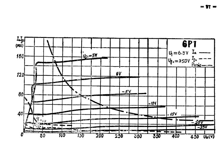
13 3. The total harmonic distortion (THD) should be less than 1 khz. 3. A. Connect two terminals of function generator with peak to peak voltage equals 1 V to the input of the tube circuit. Connect 2 terminals of oscilloscope to the plate and ground. B. Set the frequency of function generator to 1 khz, Using the tools on oscilloscope to find the THD Power Amplification Stage In power amplification stage, we will also use common cathode connection, but the screen will be connect to 230 V DC power supply. In this stage, we choose our operating point to be such that plate voltage is 200 V and plate current is 115 ma. So we will bias our 6P1 tube s grid to 0 V, in other words, no bias. From the datasheet (Fig. 07.), we found trans-conductance is 4.9 ma/v. The circuit diagram is as Fig. 08. The amplified signals will then go through output transformer and deliver electrical signal and power to the speaker. Again we calculate the dynamic plate resistance (rp) r p = V p I p = = 13333Ω eq. 6 Using the above condition μ = g m r p R p = = 17.8 eq. 7 The final voltage across the speaker can be calculated by V out = V in μ = V in = 34.2 V in eq. 8 And this is what a typical amplifier should look like [7]. 11

14 Fig. 08. I-V Curve from 6P1 Datasheet Fig. 09. Circuit Diagram Showing the Power Amp Stage 12
15 Requirements 1. The voltage gain should be greater than The frequency response should be khz minimum 3. The total harmonic distortion (THD) should be less than 1 khz. Verification 1. A. Connect two terminals of function generator with peak to peak voltage equals 0.1 V to the input of the tube circuit. Connect 2 terminals of oscilloscope to the 2 terminal of primary coil. B. Connect 2 terminal of secondary coil with a 8 Ohm resistor. C. Measure the reading from oscilloscope to make sure the output waveform has a peak to peak voltage greater than 1.0 V. 2. A. Connect two terminals of function generator with peak to peak voltage equals 1 V to the input of the tube circuit. Connect 2 terminals of oscilloscope to the plate and ground. B. Sweep the frequency of function generator from 20 to 20 khz, manually record the output waveform amplitude. C. Plot the data, make sure the khz band is at most 3 db attenuated. 3. A. Connect two terminals of function generator with peak to peak voltage equals 1 V to the input of the tube circuit. Connect 2 terminals of oscilloscope to the plate and ground. B. Set the frequency of function generator to 1 khz, Using the tools on oscilloscope to find the THD. Our overall circuit schematic will be as Fig
16 Fig. 10. Overall Circuit Diagram 2.3 Tolerance Analysis The varying resistances and capacitances will result in a different DC voltage after rectifier, it could also cause a different operating points for the tubes. The result power gain from the system would defer. Lucky, due to the linearity around the operating point, our amplification signal still obtain the same exact waveform with some unavoidable distortions. As a result, the overall power gain in the left and right channel would differ by a mount of: A left A left A left A left A left = g g m1 + R m 6J1 R out 6J1 + g Rout 6J1 g m 6P1 + R m 6P1 R out 6P1 Rout 6P1 ±0.042 A left eq. 9 A right A right A right = A right g g m1 + R m 6J1 R out 6J1 + A right g Rout 6J1 g m 6P1 + R m 6P1 R out 6P1 Rout 6P1 ±0.042 A right eq. 10 The Worst-case mismatch in the left and right channel would be: 14
17 A left + A left A left A right A right A right A left = 8.77% eq. 11 A right However, the output impedance of tube might not match input impedance of an output transformer. Due to that, the frequency response of output stage might not be ideal. And the power transformer would also differ. The main tolerance we must maintain is the frequency response of power amplify stage and impedance matching between output resistance of tube and impedance of transformer's primary coil. We can measure the output and input impedance of the output transformer in 4 ohm configuration, since AC resistance cannot be calculated easily, we use DC resistance as a reference. Speaker mismatch can be estimated as: = 1.3% eq Speaker mismatch can be estimated as: = 5.6% eq From this values above, we are able to estimate the power transfer given the power to be to best match the speakers: Right Channel Left Channel Case Speaker Resistance Transformer Resistance Speaker Resistance Transformer Resistance Power Case To left channel To right Channel Mismatch%
18 We can get a minimum of 2% mismatch in the power transfer in right and left channel. We can also use these combination with the left and right channel with the left and right channel gain to further balance the stereo channel. 16
19 3. Cost and Schedule 3.1 Cost The labor cost per hour is estimated to be $50 per person, and the average time into development is estimated to be 8 hours per week. The total labor cost can be calculated as: The cost of components is estimated to be: $50 hour 1 8 hour week 10 2 person = $ 8000 eq. 14 week person Component Cost (Prototype) Cost (Massive production) Chassis $30.9 $8.74 Different values of Capacitors, Resistors and Inductors $38 $0.73 6J1 Tube*2 $5 $1.33 6P1 Tube*2 $10 $3.0 Tube sockets *4 $3 $0.5 Output Transformer*2 $12.7 $6.36 One voltage and two power transformers $62.7 $27.3 Inputs and outputs Connectors $33.2 $6.88 Interconnect wires $20.4 $3.26 Total $215.9 $58.1 We add component cost with labor cost: $ $8000 = $8215. Which will be our total cost of human resources and prototype. 17
20 3.2 Schedule Since Simulation are almost done at the time we wrote this design document and it is against the safety rules to work on high voltages alone, we will both work on the circuit soldering and testing together as a group. Feb 12 Design, simulate all rectifier circuit. Build as much as we can. Feb 19 Feb 26 Mar 5 Mar 12 Design, simulate preamp and power amp circuit. Modify the design if needed. Maximize the theoretical gain in each stage in simulation. Soldering of Rectifier Circuit. Capture the waveform of three rectifier output voltages by the oscilloscope and perform open circuit test and load test. Soldering of Voltage Amplification Circuit (one channel). Capture the waveform of output voltage and calculate the voltage gain. Soldering of Power/Current Amplification Circuit (one channel) and output transformer connection. After safety testing hook it up with 4 ohm resistor to calculate the delivered power. Mar 19 Mar 26 April 2 Building of the Speaker Chamber, Amplifier chassis and build the impedance matching circuit for headphones. First systematic testing and Measure the frequency response of Speaker (one channel), modify the circuit to keep frequency response flat at 20-20kHz. Soldering and testing of the other channel. April 9 April 16 Match the loudness level on both channel and frequency response by tweaking the circuit Final debug and testing 18
21 4. Ethics and Safety Since our project involves with voltages that are higher than 200 volts, many components must endure the high voltages. First of all, we need to make sure we did not overload our transformers. The rating of step up 110 volt to 220 volt transformer is 1000VA, thus the maximum current on the high side should not exceed 4.54 A. For the 110 Volt to 6.8 volt transformer, the rating is 50 watts, thus the maximum current on the low side should not exceed 7.35 A. The 110 volt to 180 volt transformer has a rating of 500 VA, thus the current on high side has be limited within 2.77 A. The rectifier circuit handles a substantial power conversions, which is estimated to be 80 W, thus the rated voltages capacitors are ideally to have more than twice the actual voltage in the circuit to prevent damage to the component. Also, we choose to use resistors that can handle a maximum power of 2 W to maximize the endurance while keep the cost down. If the simulation results in a higher power consumption than 2W, we can either use a combination of resistors instead or make changes to the circuit. The diode are carefully choose to have a forward current of 1 A [8] tolerance and the repetitive reverse breakdown voltage is 1000V, which is lower than any of the transformer values. In the tube amplifier portion, the tubes are the major power consumption, the circuit design needs to ensure the maximum ratings in currents, voltages and power are not exceeded. Taking the whole product perspective, according to the first ethic guide of IEEE 7.8 [9], we need to make sure that we will not expose any metal contacts that are powered on to keep ourselves and potential customers safe. A chassis will be utilized to prevent exposure from the high voltages part of the circuit. And we will use insulation gloves if needed. For our project, the circuit part of amplifier must be sealed with good ventilation to prevent circuit and tube overheating. If the passive cooling is not sufficient enough, additional outtake and intake fans will be added. We will follow all regulations and rules of the senior design lab, in specific: 1. We will never leave any circuits unattended that might cause electric shock or scald. 2. We will always work in pairs. 3. We will make sure that all high voltage lines and equipment are properly insulated and without flaw before use. 4. We will never power on a circuit that s not finished or still in progress. 5. We will use insulating gloves if we are dealing with high voltages. 6. We will dispose broken tubes properly. 19
22 References [1] Kirkville, Are You Part of the 1% of Music Listeners?, [online]. Available at: [Accessed 22 Feb. 2018]. [2] Templeton, J., Tube vs Solid-State - Why Do Tubes Sound Better? - thetubestore Blog, [online]. Available at: [Accessed 22 Feb. 2018]. [3] Potuck, M. and Potuck, M., Report: Apple s AirPods and wireless Beats take 40% of all recent Bluetooth headphone sales, [online]. Available at: -all-recent-bluetooth-headphone-sales/ [Accessed 22 Feb. 2018]. [4] Innerfidelity.com, Apple EarPods Freq. Response, n.d.. [online]. Available at: [Accessed 22 Feb. 2018]. [5] InnerFidelity, Monster Beats by Dr. Dre Solo, [online]. Available at: [Accessed 22 Feb. 2018]. [6] McIntoshLabs, McIntosh MC275 Vacuum Tube Amplifier, [online]. Available at: Details.aspx?CatId=amplifiers&ProductId=MC275B [Accessed 22 Feb. 2018]. [7] Diyaudio.com, Typical gain for a power amp - diyaudio, [online]. Available at: -typical-gain-power-amp.html [Accessed 23 Feb. 2018]. [8] Diodes.com, 1N4001-1N A Rectifier, [online]. Available at: [Accessed 23 Feb. 2018]. [9] Ieee.org, IEEE Code of Ethics, [online]. Available at: [Accessed 6 Feb. 20
23 2018]. 21

24 Relevant Datasheets 1N4007 Diodes 22
25 6J1 Tube 23
26 24
27 25
28 26
29 6P1 Tube 27
30 28
31 29
32 30
Week 8 AM Modulation and the AM Receiver
 Week 8 AM Modulation and the AM Receiver The concept of modulation and radio transmission is introduced. An AM receiver is studied and the constructed on the prototyping board. The operation of the AM
Preface... xv Acknowledgments... xix. Chapter 1 An Overview of Vacuum Tube Audio Applications... 1
 Contents Preface... xv Acknowledgments... xix Chapter 1 An Overview of Vacuum Tube Audio Applications... 1 The Evolution of Analog Audio... 1 Technology Waves... 3 Tube vs. Solid State.................................................
EE320L Electronics I. Laboratory. Laboratory Exercise #4. Diode Rectifiers and Power Supply Circuits. Angsuman Roy
 EE320L Electronics I Laboratory Laboratory Exercise #4 Diode Rectifiers and Power Supply Circuits By Angsuman Roy Department of Electrical and Computer Engineering University of Nevada, Las Vegas Objective:
22A3 Monaural Amplifier Owner s Manual
 22A3 Monaural Amplifier Owner s Manual www.bandwidthaudio.com sales@bandwidthaudio.com WARNING Never power on the amplifier without connecting a proper load Failure to do so will result in permanent damage
2 5 1 A Va c u u m T u b e
 251A 2 5 1 A Va c u u m T u b e P L A T E L E A D INSULATORS W SPRING CONNECTOR - P L A T E L E A D -FILAMENT LEADS CONNECTOR GRID LEAD Classification The 251A Vacuum Tube is a three element, air-cooled,
Minimalist Discrete Hi-Fi Preamp
 Minimalist Discrete Hi-Fi Preamp Rod Elliott (ESP) Introduction A preamp designed for the minimalist, and having no frills at all is the design goal for this project. It is designed as a preamp for the
Hybrid Audio Frequency Amplifier
 Hybrid Audio Frequency Amplifier Kijun Yoo Robert Hasselle Faculty Mentor: Ender Ayanoglu Abstract As technologies have improved, many audio amplifier manufacturers have transitioned from vacuum tubes
3 Circuit Theory. 3.2 Balanced Gain Stage (BGS) Input to the amplifier is balanced. The shield is isolated
 Input to the amplifier is balanced. The shield is isolated") Rev. D CE Series Power Amplifier Service Manual 3 Circuit Theory 3.0 Overview This section of the manual explains the general operation of the CE power amplifier. Topics covered include Front End Operation,
Rev. D CE Series Power Amplifier Service Manual 3 Circuit Theory 3.0 Overview This section of the manual explains the general operation of the CE power amplifier. Topics covered include Front End Operation,
UNIVERSITY OF NORTH CAROLINA AT CHARLOTTE. Department of Electrical and Computer Engineering
 UNIVERSITY OF NORTH CAROLINA AT CHARLOTTE Department of Electrical and Computer Engineering Experiment No. 2 - Semiconductor Diodes Overview: In this lab session students will investigate I-V characteristics
Ear+ Purist HD. Ear+ HD II High Definition Stereo Headphone Amplifier
 Ear+ Purist HD Ear+ HD II High Definition Stereo Headphone Amplifier Users' Manual Rev Mar 8/19 Mapletree Audio Design R. R. 1, Seeley's Bay, Ontario, Canada, K0H 2N0 (613) 387-3830 www.mapletreeaudio.com
Ear+ Purist HD. Ear+ HD High Definition Stereo Headphone Amplifier
 Ear Purist HD Ear HD High Definition Stereo Headphone Amplifier 2AX7 Users' Manual ev Oct. 7/3 Mapletree Audio Design loyd Peppard.., Seeley's Bay, Ontario, Canada, K0H 2N0 (63) 387-3830 www.mapletreeaudio.com
Final Project Stereo Audio Amplifier Final Report
 The George Washington University School of Engineering and Applied Science Department of Electrical and Computer Engineering Final Project Stereo Audio Amplifier Final Report Daniel S. Boucher ECE 20-32,
The Aleph 5 is a stereo 60 watt audio power amplifier which operates in single-ended class A mode.
 Pass Laboratories Aleph 5 Service Manual Rev 0 9/20/96 Aleph 5 Service Manual. The Aleph 5 is a stereo 60 watt audio power amplifier which operates in single-ended class A mode. The Aleph 5 has only two
Lab 4: Analysis of the Stereo Amplifier
 ECE 212 Spring 2010 Circuit Analysis II Names: Lab 4: Analysis of the Stereo Amplifier Objectives In this lab exercise you will use the power supply to power the stereo amplifier built in the previous
WOO AUDIO WA2. Stereo Headphone & Pre Amplifier. Single-Ended, Class-A, Output Transformer-Less (OTL) Owner s Manual
 Owner s Manual") WOO AUDIO WA2 Stereo Headphone & Pre Amplifier Single-Ended, Class-A, Output Transformer-Less (OTL) Owner s Manual Please review this manual before operating your WOO AUDIO product. Inc. All rights reserved.
WOO AUDIO WA2 Stereo Headphone & Pre Amplifier Single-Ended, Class-A, Output Transformer-Less (OTL) Owner s Manual Please review this manual before operating your WOO AUDIO product. Inc. All rights reserved.
Professional Equalizer-Preamp Suitable for Home Use
 A combined Professional Equalizer-Preamp Suitable for Home Use KENNETH W. BETSH* Designed originally for broadcast-station use, this preamplifier can be adapted to any installation where it would be desirable
Power Supply Considerations for DDX Amplifiers
 Power Supply Considerations for DDX Amplifiers For Applications Assistance Contact: Ken Korzeniowski Apogee Technology, Inc. 19 Morgan Drive Norwood, MA 006, USA kkorz@apogeeddx.com 781-551-9450 Last Updated
Electronic Instrumentation ENGR-4300 Fall 2002 Project 2: Optical Communications Link
 Project 2: Optical Communications Link For this project, each group will build a transmitter circuit and a receiver circuit. It is suggested that 1 or 2 students build and test the individual components
Emotiva BasX A300 Stereo Power Amplifier
 Emotiva BasX A300 Stereo Power Amplifier The BasX A-300 is a two channel power amplifier that offers true audiophile sound quality at an affordable price. The BasX A-300 includes a carefully chosen set
AMP CAMP AMP #1. Introduction. Requirements and Constraints. by Nelson Pass
 AMP CAMP AMP #1 by Nelson Pass Introduction Do-It-Yourself audio is a great activity. Many major audio components are easily constructed and made to perform as well or better than what we see in the stores
Copyright 1999 Wheatfield Audio LLC. All rights reserved. Printed in USA 11/99
 HA-2 Headphone Amplifier User s Manual Contents Safety... 3 Unpacking, Setup, and Connection... 4 Unpacking the amplifier... 4 Installing the tubes... 4 Connecting the amplifier... 4 Listening with the
Ultra 4B SE Special Edition. Stereo Phono/Line Preamplifier
 Modular Series Ultra B SE Special Edition Stereo Phono/Line Preamplifier User s Manual Phono Line Line Balance Volume Mapletree Audio Design Ultra B SE Stereo Preamplifier Rev. Feb. / Mapletree Audio Design
Contents. 1. Fundamentals of Amplification The Small-Signal Pentode 40. Acknowledgements. Some Useful Formulae
 Contents Preface Acknowledgements Some Useful Formulae vii ix x 1. Fundamentals of Amplification 1 1.1: Basic Theory of Valves 2 1.2: Valve Diodes 2 1.3: Triodes 4 1.4: Anode Resistance, r a 6 1.5: Amplification
Amplifier Performance Report
 Amplifier Performance Report Report Date: February 3, 2015 Customer Name: SAMPLE Manufacturer: Dynaco Model: SCA-35 Special Notes: Amplifier appears unmodified and %100 original. It is in good overall
Experiment No.5 Single-Phase half wave Voltage Multiplier
 Experiment No.5 Single-Phase half wave Voltage Multiplier Experiment aim The aim of this experiment is to design and analysis of a single phase voltage multiplier. Apparatus Make the circuit for voltage
30 Watt Audio Power Amplifier
 30 Watt Audio Power Amplifier Including Preamp, Tone Controls, Reg dc Power Supply, 18 Watt into 8 Ohm - 30W into 4 Ohm loads Amplifier Section Circuit diagram: Audio Power Amplifier Circuit Diagram This
THÖRESS F2A11 Stereo Integrated Amplifier...
 THÖRESS F2A11 Stereo Integrated Amplifier INSTRUCTION MANUAL Thank you for purchasing the THÖRESS F2A11 Stereo Integrated Amplifier. This truly unique tube amplifier offers the music lover the possibility
F O R T H E L O V E O F M U S I C LP100 OWNER'S MANUAL AND INSTALLATION GUIDE INTRODUCTION
 F O R T H E L O V E O F M U S I C LP100 OWNER'S MANUAL AND INSTALLATION GUIDE INTRODUCTION You have purchased an amplifier that leads the way with sound quality, reliability, and features. These high performance
An Experiment with a Passive Six-Channel Volume Control for Surround Sound: The Kimber/DACT Design. February, John E. Johnson, Jr.
 Page 1 of 11 An Experiment with a Passive Six-Channel Volume Control for Surround Sound: The Kimber/DACT Design February, 2003 John E. Johnson, Jr. Introduction With all of the new music formats on CDs
Burning Amplifier #1 By Nelson Pass April 21, 2009 Rev 1.0. Nelson Pass
 Burning Amplifier #1 By Nelson Pass April 21, 2009 Rev 1.0 Introduction The Burning Amp Festival happens every October in San Francisco. Do-it-yourself audio enthusiasts from all over gather to listen
Shattered Glass Audio
 Shattered Glass Audio SGA1566 User Manual Copyright 2014 Shattered Glass Audio, a division of Creative Bytes, Inc. Introduction... 3 Signal Routing... 3 SGA1566 Circuit... 4 Equalizer... 4 Preamplifier...
FOUNTEK ALTITUDE Integrated Amplifier OWNERS MANUAL. A3500 ( Version -V1) 240V AC
 240V AC") FOUNTEK ALTITUDE 3500 Integrated Amplifier OWNERS MANUAL A3500 ( Version -V1) 240V AC 24-10-05 CONTENTS 3. INTRODUCTION 4. IMPORTANT NOTES ( WARNING!) 5. POWER INPUT CONNECTION 6. CONNECTING SPEAKERS 7.
FOUNTEK ALTITUDE 3500 Integrated Amplifier OWNERS MANUAL A3500 ( Version -V1) 240V AC 24-10-05 CONTENTS 3. INTRODUCTION 4. IMPORTANT NOTES ( WARNING!) 5. POWER INPUT CONNECTION 6. CONNECTING SPEAKERS 7.
SAFETY WARNINGS AND GUIDELINES
 SAFETY WARNINGS AND GUIDELINES For best results, please thoroughly read this manual prior to use, paying particular attention to the warnings in this Safety section: Do not expose this device to water
9 db/oct, variable bass boost
 Digital class-d linkable/dual mono block amplifier Dual MOS-FET PWM power supply Stable into 1 ohm load 24 db/oct, variable low pass filter 24 db/oct, variable subsonic filter 9 db/oct, variable bass boost
FEATURES AND BENEFITS PROMOTIONAL HIGHLIGHTS MCINTOSH LABORATORY INC., 2 CHAMBERS STREET, BINGHAMTON, NEW YORK MC206 Product Preview Page 1
 MC206 Product Preview Page 1 McIntosh Laboratory, Inc., Binghamton, NY 13903 Design Engineering Department PRODUCT BRIEF MC206 SIX CHANNEL POWER AMPLIFIER Project 1160 Contents Promotional Highlights 1
DD1-1300S. 500 Watts RMS Watts RMS Watts RMS- 1. Mono-Bloc Digital Power Amplifier
 DD1-1300S Mono-Bloc Digital Power Amplifier 500 Watts RMS- 4 900 Watts RMS- 2 Ultimate Sound, Inc. 1300 Watts RMS- 1 Ultimate Europe AB Ultimate Sound, Inc Ultimate Europe AB 163 University Parkway Flojelbergsgatan
Figure 2 shows the actual schematic for the power supply and one channel.
 Pass Laboratories Aleph 3 Service Manual rev 0 2/1/96 Aleph 3 Service Manual. The Aleph 3 is a stereo 30 watt per channel audio power amplifier which operates in single-ended class A mode. The Aleph 3
Restoration Performance Report
 Restoration Performance Report Report Date: July 15, 2015 Manufacturer: Fisher Model: 500-C Receiver Special Notes: Full Gold Level Restoration service completed. Chassis ultrasonically cleaned. All coupling
MC24O OWNER'S MANUAL STEREO POWER AMPLIFIER CONTENTS
 STEREO POWER AMPLIFIER MC24O CONTENTS GENERAL DESCRIPTION 1 TECHNICAL DESCRIPTION 1 PANEL FACILITIES 4 INSTALLATION 5 CONNECTIONS 5 Input Stereo 5 Input Twin Amp 5 Input Mono 6 Output Stereo or Twin Amp
2) The larger the ripple voltage, the better the filter. 2) 3) Clamping circuits use capacitors and diodes to add a dc level to a waveform.
 The larger the ripple voltage, the better the filter. 2) 3) Clamping circuits use capacitors and diodes to add a dc level to a waveform.") TRUE/FALSE. Write 'T' if the statement is true and 'F' if the statement is false. 1) A diode conducts current when forward-biased and blocks current when reverse-biased. 1) 2) The larger the ripple voltage,
TRUE/FALSE. Write 'T' if the statement is true and 'F' if the statement is false. 1) A diode conducts current when forward-biased and blocks current when reverse-biased. 1) 2) The larger the ripple voltage,
Threshold Noise-Cancelling Headphones
 1 Threshold Noise-Cancelling Headphones By: Nicholas Dennis CD Holder David Toft Final Report for ECE 445, Senior Design, Fall 2016 TA: Cara Yang May 4th, 2016 Project No. 57 2 Abstract Our project is
FEATURES FRONT PANEL. INPUT : Use this jack to connect your instrument via a standard ¼ mono cable.
 OWNER S MANUAL 2018 ended up as the most important year in Darkglass history. With groundbreaking new products, renewed classic releases, and limited-edition pedals, our product catalog grew stronger than
MC2301. Features and Benefits. Promotional Highlights TUBE POWER AMPLIFIER MCINTOSH LABORATORY INC., 2 CHAMBERS STREET, BINGHAMTON, NEW YORK 13903
 MC2301 Product Preview Page 1 McIntosh Laboratory, Inc., Binghamton, NY 13903 Design Engineering Department PRODUCT PREVIEW MC2301 TUBE POWER AMPLIFIER Project 1336 Promotional Highlights 300 Watts Mono
FEATURES FRONT PANEL. INPUT : Use this jack to connect your instrument via a standard ¼ mono cable.
 OWNER S MANUAL 2018 ended up as the most important year in Darkglass history. With groundbreaking new products, renewed classic releases, and limited-edition pedals, our product catalog grew stronger than
AMPLIFIERS BI BI BI BI4400.4
 LIMITED WARRANTY Bass Inferno warrants any products purchased in the U.S.A. from an authorized Bass Inferno dealer. All products are warranted to be free from defects in material and workmanship under
Kaskode One Phono Preamplifier Owner s Manual
 Kaskode One Phono Preamplifier Owner s Manual www.bandwidthaudio.com sales@bandwidthaudio.com WARNING Configuration of the Kaskode One will require removing the cover of the unit. Before removing the cover
Thank you very much for choosing Shuguang Audio Classic Series vacuum tube amplifier
 Thank you very much for choosing Shuguang Audio Classic Series vacuum tube amplifier (845 version). When opening the package, please carefully unpack all tubes and install each tube to its marked location
IMPORTANT SAFETY INSTRUCTIONS
 IMPORTANT SAFETY INSTRUCTIONS When using this electronic device, basic precautions should always be taken, including the following: 1. Read all instructions before using the product. 2. Do not use this
Project 1 Final System Design and Performance Report. Class D Amplifier
 Taylor Murphy & Remo Panella EE 333 12/12/18 Project 1 Final System Design and Performance Report Class D Amplifier Intro For this project, we designed a class D amplifier circuit. Class D amplifiers work
Amplifier Performance Report
 Amplifier Performance Report Report Date: February 30, 2015 Customer Name: (unsold) Manufacturer: Fisher Model: KX-100 Special Notes: Full Gold Level Restoration service completed. Chassis ultrasonically
DIY: from vinyl to compact disk
 AUDIO & HI-FI DIY: from vinyl to compact disk with a PC and sound card Nowadays, with the availability of personal computers and compact-disk (CD) writers, there is nothing in the way of transferring one
NEW. HANDMADE in Germany.
 NEW HANDMADE in Germany. Integrated amplifier Ti 100 Mk II The Lyric Ti 100 Mk II is a pure single-ended class A amplifier. Its subtlety, naturalness, charm and dynamics converge for a fantastic listening
[Q] DEFINE AUDIO AMPLIFIER. STATE ITS TYPE. DRAW ITS FREQUENCY RESPONSE CURVE.
![[Q] DEFINE AUDIO AMPLIFIER. STATE ITS TYPE. DRAW ITS FREQUENCY RESPONSE CURVE.](/thumbs/86/94105671.jpg "[Q] DEFINE AUDIO AMPLIFIER. STATE ITS TYPE. DRAW ITS FREQUENCY RESPONSE CURVE.") TOPIC : HI FI AUDIO AMPLIFIER/ AUDIO SYSTEMS INTRODUCTION TO AMPLIFIERS: MONO, STEREO DIFFERENCE BETWEEN STEREO AMPLIFIER AND MONO AMPLIFIER. [Q] DEFINE AUDIO AMPLIFIER. STATE ITS TYPE. DRAW ITS FREQUENCY
TOPIC : HI FI AUDIO AMPLIFIER/ AUDIO SYSTEMS INTRODUCTION TO AMPLIFIERS: MONO, STEREO DIFFERENCE BETWEEN STEREO AMPLIFIER AND MONO AMPLIFIER. [Q] DEFINE AUDIO AMPLIFIER. STATE ITS TYPE. DRAW ITS FREQUENCY
Diode Characteristics and Applications
 Diode Characteristics and Applications Topics covered in this presentation: Diode Characteristics Diode Clamp Protecting Against Back-EMF Half-Wave Rectifier The Zener Diode 1 of 18 Diode Characteristics
THE HONG KONG POLYTECHNIC UNIVERSITY EN107/1 Department of Electronic and Information Engineering. EN107: OCL Class AB Power Amplifier Objective
 THE HONG KONG POLYTECHNIC UNIVERSITY EN107/1 EN107: OCL Class AB Power Amplifier Objective 1. To study the circuit performance of an OCL amplifier. 2. To study the effects of biasing on cross-over distortion
The Alpha Omega 900 amplifies the best qualities of one of the most powerful and distinct Darkglass pedals ever made.
 OWNER S MANUAL The Alpha Omega 900 takes the best elements of our most successful distortion preamplifier ever, combined with state-of-the-art features to make a monstrous 900-watt amplifier with earth-shattering
Western E/ectrk A V a c u u m T u b e
 295A Western E/ectrk 2 9 5 A V a c u u m T u b e Classification Filamentary air- cooled triode May be used as an audio-frequency amplifier or as a radio-frequency amplifier, modulator o r o s c i l l a
Device Interconnection
 Device Interconnection An important, if less than glamorous, aspect of audio signal handling is the connection of one device to another. Of course, a primary concern is the matching of signal levels and
Western Electric D V a c u u m T u b e
 284D Western Electric 2 8 4 D V a c u u m T u b e Classification Fiiamentary air-cooied triode The tube is designed primarily for use as an audio-frequency amplifier or modulator and may be used as a replacement
A Simple Notch Type Harmonic Distortion Analyzer
 by Kenneth A. Kuhn Nov. 28, 2009, rev. Nov. 29, 2009 Introduction This note describes a simple notch type harmonic distortion analyzer that can be constructed with basic parts. It is intended for use in
Grounded Grid Plus Vacuum Tube Preamplifier User Manual. Analog Metric
 Grounded Grid Plus Vacuum Tube Preamplifier User Manual Analog Metric Page 2 INTRODUCTION This Grounded Grid Plus preamplifier provides enhanced performance out of the original Grounded Grid design. This
Now For Something Completely Different: the F7 Power Amplifier. Short Story Long:
 Now For Something Completely Different: the F7 Power Amplifier Short Story Long: Conceived in 2007, the F5 was a push-pull Class A amplifier employing eight semiconductors and 23 resistors to achieve 25
2. Avoid metal objects coming into contact with this product. Protect the solder joints on the bottom of the PCB when mounting this product.
 User s Guide and Specifications AMP2X15 Audio Amplifier Board PUI Audio s AMP2X15 audio amplifier board features a Texas Instruments TPA3110D2 Class D amplifier circuit for maximum signal fidelity; delivering
ECE 203 ELECTRIC CIRCUITS AND SYSTEMS LABORATORY SPRING No labs meet this week. Course introduction & lab safety
 ECE 203 ELECTRIC CIRCUITS AND SYSTEMS LABORATORY SPRING 2019 Week of Jan. 7 Jan. 14 Jan. 21 Jan. 28 Feb. 4 Feb. 11 Feb. 18 Feb. 25 Mar. 4 Mar. 11 Mar. 18 Mar. 25 Apr. 1 Apr. 8 Apr. 15 Topic No labs meet
Audio Amplifier. November 27, 2017
 Audio Amplifier November 27, 2017 1 Pre-lab No pre-lab calculations. 2 Introduction In this lab, you will build an audio power amplifier capable of driving a 8 Ω speaker the way it was meant to be driven...
Block-800B bass head. user manual
 Block-800B bass head user manual Musikhaus Thomann Thomann GmbH Hans-Thomann-Straße 1 96138 Burgebrach Deutschland Telephone: +49 (0) 9546 9223-0 E-mail: info@thomann.de Internet: www.thomann.de 08.03.2018,
AN174 Applications for compandors SA570/571 SA571
 RF COMMUNICATIONS PRODUCTS Applications for compandors SA570/571 SA571 1997 Aug 20 Philips Semiconductors APPLICATIONS The following circuits will illustrate some of the wide variety of applications for
User Manual. MA 240 Mixing amplifier
 User Manual MA 240 Mixing amplifier Safety instructions When using this electronic device, basic precautions should always be taken, including the following: 1 Read all instructions before using the product.
AMPLIFIERS. Bi2200Tx Bi4200Fx. Bi1400Mx Bi2400Mx Bi3000Mx
 LIMITED WARRANTY Bass Inferno warrants any products purchased in the U.S.A. from an authorized Bass Inferno dealer. All products are warranted to be free from defects in material and workmanship under
Lab E5: Filters and Complex Impedance
 E5.1 Lab E5: Filters and Complex Impedance Note: It is strongly recommended that you complete lab E4: Capacitors and the RC Circuit before performing this experiment. Introduction Ohm s law, a well known
Astronomical Society of Victoria Inc.
 Radio Astronomy Section. 1.0 Background The natural phenomena of lightning generates electromagnetic waves over a broad spectrum of frequencies. A substantial component of the energy occurs in the spectrum
IPR LA-3 KIT last update 15 march 06
 IPR LA-3 KIT last update 15 march 06 PART-2: Audio Circuitry CIRCUIT BOARD LAYOUT: Power and Ground Distribution Now that your power supply is functional, it s time to think about how that power will be
Federal Urdu University of Arts, Science & Technology Islamabad Pakistan SECOND SEMESTER ELECTRONICS - I
 SECOND SEMESTER ELECTRONICS - I BASIC ELECTRICAL & ELECTRONICS LAB DEPARTMENT OF ELECTRICAL ENGINEERING Prepared By: Checked By: Approved By: Engr. Yousaf Hameed Engr. M.Nasim Khan Dr.Noman Jafri Lecturer
Owner s Manual 900.4M. 4 ch MARINE amplifier. reaudio.com
 Owner s Manual 900.4M 4 ch MARINE amplifier reaudio.com THANK YOU for purchasing RE AUDIO Bluetooth MARINE amplifiers BT-900.4M. With almost no sacrifice on sound quality, BT-900.4M easily plays the music
Design Project: Sensitive audio detector
 Design Project: Sensitive audio detector This worksheet and all related files are licensed under the Creative Commons Attribution License, version 1.0. To view a copy of this license, visit http://creativecommons.org/licenses/by/1.0/,
Lab 9 Frequency Domain
 Lab 9 Frequency Domain 1 Components Required Resistors Capacitors Function Generator Multimeter Oscilloscope 2 Filter Design Filters are electric components that allow applying different operations to
RSS twitter facebook linked in. Home Reviews Press A/V Directory CAVE Technical Articles. Home Preamplifiers Classe CP-800 Stereo Preamplifier
 RSS twitter facebook linked in YOUR EMAIL SUBMIT Like Home Reviews Press A/V Directory CAVE Technical Articles Home Preamplifiers Classe CP-800 Stereo Preamplifier Classe CP-800 Stereo Preamplifier Written
SLP-2002 Stereo Balanced Vacuum Tube Preamplifier
 SLP-2002 Stereo Balanced Vacuum Tube Preamplifier Fully Balanced Vacuum Tube Line Stage Circuit Design with Cinema Bypass and Remote Volume Control CARY AUDIO DESIGN 1020 GOODWORTH DRIVE APEX, NORTH CAROLINA
OWNER' S MANUAL THE DAVID BERNING COMPANY ZH270 POWER AMPLIFIER
 OWNER' S MANUAL THE DAVID BERNING COMPANY ZH270 POWER AMPLIFIER The David Berning Company 12430 McCrossin Lane Potomac, Maryland 20854 USA (301) 926-3371 www.davidberning.com WARNING: For safety, the cover
The Micromega MyAMP. A serious design challenge
 The Micromega MyAMP A serious design challenge Following the successful launch of the MyDAC, MyZIC and MyGROOV, the Micromega engineers had a serious design challenge: to complete the MY range by adding
A 4000 A Owner s Manual HPA HPA A4000 A5000 PROFESSIONAL POWER AMPLIFIER POWER CHANNEL 2 CHANNEL 1 PROFESSIONAL POWER AMPLIFIER POWER CHANNEL 2
 Owner s Manual A 000 A 000 PROFESSIAL POWER AMPLIFIER CHANNEL POWER PROTECT CLIP -0dB -0dB SIGNAL ACTIVE A000 CHANNEL HPA 0 9 0 9 9 0 9 0 9 9 PROFESSIAL POWER AMPLIFIER CHANNEL POWER PROTECT CLIP -0dB
Electrical Engineer. Lab2. Dr. Lars Hansen
 Electrical Engineer Lab2 Dr. Lars Hansen David Sanchez University of Texas at San Antonio May 5 th, 2009 Table of Contents Abstract... 3 1.0 Introduction and Product Description... 3 1.1 Problem Specifications...
ELECTRICITY AND ELECTRONICS
 ELECTRICITY AND ELECTRONICS (Maximum Marks: 100) (Time allowed: Three hours) (Candidates are allowed additional 15 minutes for only reading the paper. They must NOT start writing during this time.) Answer
LeMay Audio Products. MK-I Preamplifier Users Manual John P. LeMay All Rights Reserved Rev A
 LeMay Audio Products MK-I Preamplifier Users Manual 2008 John P. LeMay All Rights Reserved Rev A 08.12.24 Congratulations on purchasing one of the world s finest professional instrument preamplifiers!
RF Power Amplifier (RFPA) Designing a 'Output Tank Circuit'
 Designing a 'Output Tank Circuit'") RF Power Amplifier (RFPA) Designing a 'Output Tank Circuit' By Larry E. Gugle K4RFE, RF Design, Manufacture, Test & Service Engineer (Retired) Figure-1 Output 'Tank' Circuit Network in Low-Pass Filter
RF Power Amplifier (RFPA) Designing a 'Output Tank Circuit' By Larry E. Gugle K4RFE, RF Design, Manufacture, Test & Service Engineer (Retired) Figure-1 Output 'Tank' Circuit Network in Low-Pass Filter
Linear. Headphone amplifier / Single Source Preamp. User manual
 Linear Headphone amplifier / Single Source Preamp User manual Lehmannaudio Manual Linear - page 2 - Dear customer, congratulations for buying the Lehmannaudio Linear. You will be rewarded with the best
CABINET POWERED MIXING CONSOLE
 R SHS AUDIO SPMU- 00 CABINET POWERED MIXING CONSOLE USER'S MANUAL SAFETY INSTRUCTIONS SPECIFICATIONS Inputs Input modes Input Impedance Rated Input level Connector WARNING - TO REDUCE THE RISK OF FIRE
WOO AUDIO WA6 2nd Gen
 WOO AUDIO WA6 2nd Gen Single-Ended Class-A Stereo Headphone Amplifier Owner s Manual Please review this manual before operating your WOO AUDIO product. CHANGE LOG: March 29, 2017. Changed tubes from 6DE7
Professional Fidelity Mastering Grade Listening
 Professional Fidelity Mastering Grade Listening OFF 150 220 330 Phonos 100 220 470 2k2 4k7 10k -10 ON MM MC Norm +4 Off On GAIN SUBSONIC CAPACITANCE pf IMPEDANCE Ω VOLTAiR 120V DC Audio Rail RIAA Phono
audionet 4 Channel Amplifier Owner's Manual
 audionet amp Iv 4 Channel Amplifier Owner's Manual Congratulations! For those in need of even more amplification we have engineered the AMP IV. The AMP IV is our power amplifier for multichannel applications
PartIIILectures. Multistage Amplifiers
 University of missan Electronic II, Second year 2015-2016 PartIIILectures Assistant Lecture: 1 Multistage and Compound Amplifiers Basic Definitions: 1- Gain of Multistage Amplifier: Fig.(1-1) A general
mix 502, mix 802, mix 1202FX mixer user manual
 mix 502, mix 802, mix 1202FX mixer user manual Musikhaus Thomann Thomann GmbH Hans-Thomann-Straße 1 96138 Burgebrach Germany Telephone: +49 (0) 9546 9223-0 E-mail: info@thomann.de Internet: www.thomann.de
transformer rectifiers
 Power supply mini-project This week, we finish up 201 lab with a short mini-project. We will build a bipolar power supply and use it to power a simple amplifier circuit. 1. power supply block diagram Figure
PA System in a Box. Edwin Africano, Nathan Gutierrez, Tuan Phan
 PA System in a Box Edwin Africano, Nathan Gutierrez, Tuan Phan Overview A public address system (PA System) is an electronic sound distribution system that allows music and speech to reach a large amount
User Manual (English)
") Psvane TC5 Integrated KT120 Tube Amplifier User Manual (English) 1 P a g e Exclusively available at www.grantfidelity.com All copy rights reserved by Psvane Audio & Grant Fidelity page I Warnings: 1. Before
Psvane TC5 Integrated KT120 Tube Amplifier User Manual (English) 1 P a g e Exclusively available at www.grantfidelity.com All copy rights reserved by Psvane Audio & Grant Fidelity page I Warnings: 1. Before
Unit/Standard Number. LEA Task # Alignment
 1 Secondary Competency Task List 100 SAFETY 101 Demonstrate an understanding of State and School safety regulations. 102 Practice safety techniques for electronics work. 103 Demonstrate an understanding
7 Watt Audio Amplifier with TDA2003
 7 Watt Audio Amplifier with TDA2003 Schematic diagram of a simple 7 watt audio amplifier using TDA2003 Amplifier IC. This is a good IC with many built in features like low harmonic distortion, short circuit
Tube headphone amp schematic
 Tube headphone amp schematic headphones, so no negative feedback was employed in the execution. 125mA plate current. There are no plate curves in my RCA manual for the 6AS7G, second-order harmonics with
EE 332 Design Project
 EE 332 Design Project Variable Gain Audio Amplifier TA: Pohan Yang Students in the team: George Jenkins Mohamed Logman Dale Jackson Ben Alsin Instructor s Comments: Lab Grade: Introduction The goal of
Thank you for purchasing this Rockville Power Gig RPG152K Bluetooth pro audio speaker system.
 OWNER S MANUAL Thank you for purchasing this Rockville Power Gig RPG52K Bluetooth pro audio speaker system. We are very proud to bring you what we consider to be the absolute best value line pro audio