To make this design more accessible, is offering a limited number of kits for this design including VFETs, pc boards, and hardware.
|
|
|
- Sharyl Alisha Townsend
- 6 years ago
- Views:
Transcription
1 The DIY Sony VFET by Nelson Pass This is an addendum to the Sony SIT AMP part 2 article is the second of a series presenting Do-It-Yourself audio power amplifiers using Static Induction Transistors (SITs), also known as VFETs. These are unusual transistors with a characteristic similarity to Triode tubes. Here we are concerned with a modified version of the amplifier where we use only one pair of the VFET transistors per channel. The motivation for this is so that DIYers can build their own versions of the amplifier with the very limited quantities of the VFETs which are available. To make this design more accessible, is offering a limited number of kits for this design including VFETs, pc boards, and hardware. I refer you to previous articles (in pdf format) linked below. I recommend looking at these for background material Sony VFET Part Sony VFET Part Sony VFET 40 Year Commemorative Amplifier 2011 SIT Introduction 2012 SIT Nemesis 2011 SIT-1 Owner's Manual 2011 SIT-2 Owner's Manual If you have absorbed the contents of the previous articles, you probably have a good picture of what is going on. This project is simply a simplification of the Part 2 article, and virtually all you can see their will apply to this project, so you will want to pay particular attention to that.
2 Here is the revised version of the circuit: Comparing it to Part 2, you see that there is only one pair of the VFETs, that the input cascode transistors Q3 and Q4 are biased only by resistors, and that the regulators Q7 and Q8 are no longer bootstrapped by the output signal. Also, there is no longer a provision for no-feedback operation (we need the feedback here with the smaller output stage) and also no cascode feedback. Although still complex, it is a simpler circuit that Part 2, and more likely to be successfully built. Numerous resistor and transistor values have been adjusted, no big deal.

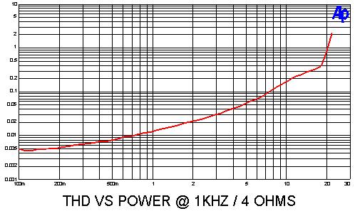
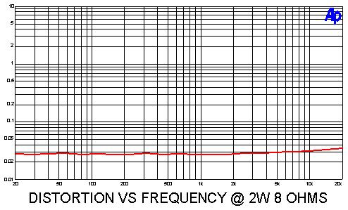
3 Construction Notes: As with Part 2, I used an ordinary First Watt type supply design, documented elsewhere, with 22 VAC transformer secondaries to provide +/-28 volts DC. 24 or 25 VAC will work fine, running a little hotter. Later we will discuss changes to resistor values for different rail voltages. Also we will be giving more organized test procedures to maximize the probability of success in that scary moment when the power is first applied. This article pretty much assumes that you are using the kit supplied by DIYAudio. The VFETs provided with it are already tested and graded with a number which represents the bias voltage for 0.5 amps of current. DIYaudio also offers a couple of chassis for this project, and the bracket which comes with the kit is designed to mount on one of their heat sinks. There is nothing unusual regarding the construction of this amplifier. All the usual cautions and advice about building power amplifiers apply. There will be a construction thread and build video by 6L6 in the Pass Labs forum at DIYAudio. Performance Notes: The amplifier delivers 15 watts into 8 ohms and 20 watts into 4 ohms. This is less power that Part 2, and reflects the single pair of VFETs. The open loop gain is about 36 db without a load, and 35 db with an 8 ohm load, and the closed loop gain is 16 db. The output impedance is 0.18 ohms, a damping factor of 45. Here are the curves:
4

5 This is a curve showing the Class A envelope - current still going through the unused VFET at 15 watt rms (30 w peak) into 8 ohms. You can see that there is still about 100 ma bias left on the unused half of the amplifier at this point. For reference, this is the artwork for the circuit board supplied in the kit. Green is the bottom traces, red is the top. Component numbers, polarities, and voltage test points are silk screened in white on the top of the board.
6 TESTING NOTES The following notes are intended as an aid to initial testing and adjustment of this advanced do-it-yourself project. It is assumed that the builder has the skills and knowledge to safely tackle a project like this and is prepared to take responsibility for the results. PART 1 TESTING THE RESISTORS Here we will perform an early test to see if we have errors in resistor stuffing before we start putting in other parts. This will might just save us all sorts of trouble later on. All resistors stuffed and soldered, no semiconductors or capacitors. All potentiometers set to halfway position. With digital ohmmeter, measure resistance between test points to about 5%. Don't get too excited if they aren't exact. Don't have an ohmmeter? Get one. POINTS OHMS POINTS OHMS T6 T T8 T T2 T6 2.1K T1 T4 2.1K T6 T7 47 T8 T9 47 T6 T19 1.9K T8 T20 1.9K T12 T T10 T T6 T T8 T G T18 7.5K G IN 49K G T19 3.9K G T20 3.9K G T K G T K G T2 4.9K G T4 4.9K G V+ 3.1K G V- 3.1K
7 PART 2 APPLYING POWER TO THE FRONT END Circuit voltages with semis and capacitors stuffed NO VFETs yet. *** Pots P3 and P4 set fully counterclockwise *** Power supply attached with V+ = +28V, V- = -28V. See notes at end for other supply voltages. Initial Voltages at test points: POINTS VOLTS POINTS VOLTS G T6 +28V G T8-28V G T4-24V G T2 +24V T6 T7 0V T8 T9 0V T6 T11 ~ 5V T8 T13 ~ 5V G T18 less than a few +/- volts (will adjust later) G T14 +13V G T15-13V G T19 ~+12V G T20 ~-12V G T17 ~-10V G T16 ~+10V PART 3 - BIASING UP THE FRONT END Assuming you acquired them from DIYAudio, your VFETs will have a Vgs rating written on them in tenths of volts (rating of 70 is 7.0 Volts, and rating of 101 is 10.1 Volts). We want to set the voltages so the amplifiers comes up initially with low bias. The following voltages are reference to Ground.
8 Adjust P1 for T16 equals the Vgs of 2SJ28 + 1V ( example: 68 wants +7.8V) Adjust P2 for T17 equals the Vgs of 2SK82 1V (example: 92 wants -10.2V) Now we are going to bias up the front end Mosfets. We will be looking at the voltage drops across R5 (T6 and T7) and R6 (T8 and T9) as well as the DC offset at T18 (relative to ground) while adjusting the trim pots P3 and P4 We are looking to achieve about 1.5 volts across R5 and R6 and close to 0 volts measured T18, which is the output of the front end circuit. If your initial voltages across R5 and R6 with P3 and P4 counter-clockwise is above 1 volt, it is likely that either your Q1 and Q2 Jfets have particularly high Idss values and/or your Mosfets Q5 and Q6 have a low Vgs. If you encounter this, I suggest that you note the voltage drop between T6 and T11 and also between T8 and T13 and ask for help on the DIYAudio Pass Labs forum. Do not continue to operate the circuit with R5 or R6 voltage drops above 2 V. We start with P3 and P4 at counterclockwise positions which should be minimum bias, and ideally there will be no voltage across R5 and R6. If you have voltage drops between 0 and 1 volt, you are still fine. If the initial voltage is above 1 volt, skip to the end of Part 3. We are now going to adjust P3 and P4 with the following rotating procedure: Step 1 Check voltage across R5 (T6 to T7) and compare it to R6 (T8 to T9). If the voltage across R5 is less than 1.2V and is lower than the voltage across R6, then adjust P3 clockwise to increase it by 0.1V otherwise go to Step 2 Step 2 Check voltage across R6 (T8 to T9) and compare it to R5 (T6 to T7). If the voltage across R6 is less than 1.2V and is lower than the voltage across R5, then adjust P4 clockwise to increase it by 0.1V Repeat until the voltages across R5 and R6 are both at 1.2V, matched as closely as you can get them. At this point, the output voltage T18 should be fairly close to 0V. By tweaking the values of R5 or R6 very gently, you should be able to get T18 to be fairly close to 0V while holding the resistor drops at about 1.2V
9 At this point the circuit needs to warm up, and as it does the voltage across R5 and R6 (and thus the bias current of this stage) will rise a bit. If it climbs above 1.5V, it will need to be adjusted downward, and the output offset re-adjusted. If it doesn't rise to 1.5V, you can repeat the procedure to raise the value. Keep in mind that this is a good time to get these values and a low DC offset right. It becomes a little more complicated when the VFETs are installed and the feedback loop starts working. Now readjust P1 and P2, as the adjustments of P3 and P4 will have slightly altered the voltages at T16 and T17. Run it this way for a bit, and tweak the pots again for the desired voltages as outlined in this section, keeping in mind that each tweak will slightly alter the other values. Halfway adjustments are still recommended. If it looks reasonably stable over a period of time, then we are ready for the final assembly and tests. PART 4 INSTALLING VFETS AND ADJUSTMENT At this point, you install the VFETs and prepare to fire up the amplifier. The previous instructions were intended to help you isolate and solve problems in the circuit prior to this step to minimize the chance that the rare and expensive VFETs will not be damaged at this point. If you have a Variac for this, you will want to use it, but keep in mind that it is only useful for providing a relatively low inrush current to the power supply capacitance you cannot raise the AC line voltage too slowly or you risk having the VFETs draw too much current while the bias voltages are being established. I suggest that you raise the AC line to voltage over a period of less than 5 seconds. It's also a good idea to connect the channels up separately so that you are dealing with one at a time. Until things are working, one channel at a time gets power supply V+ and V-. I also suggest that you start out with the lowest possible line fuse that can survive the modest inrush provided by the Variac. 1 amp fast blow is a good start, and has a reasonable chance of protecting the circuit.
10 If you don't have a Variac, you will probably need a higher value, but keep it at a minimum until you know the circuits are OK. If the 1 amp fuse survives, take a look at the voltages across R32 on each channel (test points -28V to T1) With a little luck it will be less than 100 mv. If it is higher, shut it down, adjust P1 and P2 counterclockwise a bit and try again. If that doesn't work, then stop and get help. Ideally, the R32 voltage drop will be about 50 mv or less, and you can move on to adjusting the output stage bias current and DC offset voltage. You do not need a load at the output for this. For this procedure you will be adjusting P1 and P2 while keeping an eye on the voltage drop across the.1 ohm power resistor R32 and also on the DC offset voltage at the amplifier's output. We will be looking to achieve 100 mv DC across R32 while also having close to 0 volts DC at the output. It's very helpful if you have two voltmeters, but you can do it with one. The target DC offset value will be 0 microvolts, but we will allow +/- 50 mv at the output. If you can do better, then that's good too. Assuming that the voltage across R32 is less than 100 mv, you can adjust P1 and P2 in rotation much the same way as you did with P3 and P4. Don't try to just set it at the right value first time these pots interact with each other, so go toward the desired values in small increments. With a little practice you will get the hang of it, and it does require patience, particularly as this has to be played with while the amplifier warms up the values will drift a little with temperature. If you are successful, and the amplifier runs for an hour or so without running away, either with the voltages across R5 and R6, or R32 or the DC offset at the output, then probably you are safe to hook up a loudspeaker and see how it sounds. If you need to tweak any of the pots, remember to do it in halfway steps, checking and adjusting the other bias values as you go along. If you think you're ready to go, one last piece of advice: Start with cheap speakers. (Note how much the amplifier improves their performance...) 2016 First Watt
11 NOTES ON SUPPLY VOLTAGES NOT +/-28V This amplifier is designed to operate with voltages between about +/-26V DC and +/-30V DC. If your supply is lower than this, you should adjust R15 and R16 down so that the R19 and R20 have at least 2 volts across them. For example, if the supplies are +/-24V as measured at T6 and T8 (relative to ground) then the regulators Q13 and Q14 need to be set for 2 volts below that at 22V each. To compute the new value of R15 and R16: 22V = 2.5V * (R ohms)/4750 ohms 22V *4750 ohms / 2.5V = R ohms ohms = R ohms R15 = ohms. You would pick the closest 1% resistor, which would be 36K or 36.5K for R15 and R16. Other parts of the circuit are not very sensitive to supply values. Practically speaking, you should not try to make this amplifier with rail voltages below 20 volts, and above 32 volts.
Part 1: Common Source Mode, Transformer Coupled
 Sony VFETs in Push-Pull Class A Part 1: Common Source Mode, Transformer Coupled By Nelson Pass Introduction This article is the first of a series presenting fairly simple Do-It-Yourself audio power amplifiers
Burning Amp 2. by Nelson Pass. Introduction. Concept
 Burning Amp 2 by Nelson Pass Introduction In Burning Amp 1 we examined an amplifier circuit designed to complement the hardware we gave away to some attendees at last October's Burning Amp Festival in
Figure 2 shows the actual schematic for the power supply and one channel.
 Pass Laboratories Aleph 3 Service Manual rev 0 2/1/96 Aleph 3 Service Manual. The Aleph 3 is a stereo 30 watt per channel audio power amplifier which operates in single-ended class A mode. The Aleph 3
The Aleph 2 is a monoblock 100 watt audio power amplifier which operates in single-ended class A mode.
 Pass Laboratories Aleph 2 Service Manual Rev 0 2/1/96 Aleph 2 Service Manual. The Aleph 2 is a monoblock 100 watt audio power amplifier which operates in single-ended class A mode. The Aleph 2 has only
AMP CAMP AMP #1. Introduction. Requirements and Constraints. by Nelson Pass
 AMP CAMP AMP #1 by Nelson Pass Introduction Do-It-Yourself audio is a great activity. Many major audio components are easily constructed and made to perform as well or better than what we see in the stores
Burning Amplifier #1. By Nelson Pass 1/22/09. Introduction. Hardware. Concept
 Burning Amplifier #1 By Nelson Pass 1/22/09 Introduction The Burning Amp Festival is an event every October in San Francisco. Do-it-yourself audio enthusiasts from all over gather to show off their projects,
Burning Amplifier #1 By Nelson Pass April 21, 2009 Rev 1.0. Nelson Pass
 Burning Amplifier #1 By Nelson Pass April 21, 2009 Rev 1.0 Introduction The Burning Amp Festival happens every October in San Francisco. Do-it-yourself audio enthusiasts from all over gather to listen
Now For Something Completely Different: the F7 Power Amplifier. Short Story Long:
 Now For Something Completely Different: the F7 Power Amplifier Short Story Long: Conceived in 2007, the F5 was a push-pull Class A amplifier employing eight semiconductors and 23 resistors to achieve 25
The Aleph 5 is a stereo 60 watt audio power amplifier which operates in single-ended class A mode.
 Pass Laboratories Aleph 5 Service Manual Rev 0 9/20/96 Aleph 5 Service Manual. The Aleph 5 is a stereo 60 watt audio power amplifier which operates in single-ended class A mode. The Aleph 5 has only two
Construction notes for the symmetrical 400 watt amplifier
 Construction notes for the symmetrical 400 watt amplifier Introduction The symmetrical amplifier is an update of one of my designs, which appeared in the Australian electronics magazine Silicon Chip in
First Watt SIT-3 Power Amplifier
 First Watt SIT-3 Power Amplifier OWNERS MANUAL Introduction The SIT-3 is the very latest example of single-ended / single-stage Class A amplifiers using the SIT (aka VFET) power transistor exclusive to
So far, First Watt has made a few different amplifiers: Very different amplifiers.
 First Watt model F5 Operation and Service Manual So far, First Watt has made a few different amplifiers: Very different amplifiers. Quite a few people have asked me for a regular sort of amplifier, you
PM124 Installation Instructions. See important note about revisions of this board on the last page.
 Marchand Electronics Inc. PO Box 473, Webster, NY 14580 Tel:(716) 872-0980 Fax:(716) 872-1960 info@marchandelec.com http://www.marchandelec.com (c)1997 Marchand Electronics Inc. PM124 Installation Instructions
PM24 Installation Instructions
 Marchand Electronics Inc. PO Box 473, Webster, NY 14580 Tel:(716) 872-0980 Fax:(716) 872-1960 info@marchandelec.com http://www.marchandelec.com (c)1997 Marchand Electronics Inc. PM24 Installation Instructions
The Pearl II Phono Stage. By Wayne Colburn. Introduction
 The Pearl II Phono Stage By Wayne Colburn Introduction Here is the long awaited sequel to the Pearl phono stage, named after my maternal Grandmother who was good with a sling shot, played piano and organ
Copyright 1999 Wheatfield Audio LLC. All rights reserved. Printed in USA 11/99
 HA-2 Headphone Amplifier User s Manual Contents Safety... 3 Unpacking, Setup, and Connection... 4 Unpacking the amplifier... 4 Installing the tubes... 4 Connecting the amplifier... 4 Listening with the
The Zen Variations - Part 2
 The Zen Variations - Part 2 The Penultimate Zen s Current Source by Nelson Pass, (c) 2002 Pass Laboratories Intro Welcome back to the Zen Amp Variations. This is part 2 of many parts in which we explore
Operation and Maintenance Manual
 WeiKedz 0-30V 2mA-3A Adjustable DC Regulated Power Supply DIY Kit Operation and Maintenance Manual The WeiKedz Adjustable DC Regulated Power Supply provides continuously variable output voltage between
THE ZEN TRIODE EXPIREMENTERS AMPLIFIER KIT MODEL SE84CDIYMONO
 THE ZEN TRIODE EXPIREMENTERS AMPLIFIER KIT MODEL SE84CDIYMONO ASSEMBLY INSTRUCTIONS 2008 The circuit board has been designed to be used in 2 ways; A) Mounted on stand-offs to a piece of wood and B) Mounted
Balanced Zen Line Stage. Introduction
 Balanced Zen Line Stage Introduction The popularity of the Zen projects points out the interest in very simple linear circuits. They are intended to fuel that interest. The Zen, Bride of Zen, and Son of
This power amplifier is just such a piece of low hanging fruit.
 De-Lite Amplifier by Nelson Pass Introduction The third annual Burning Amp Festival was held in San Francisco last October, drawing a couple hundred DIY Audio enthusiasts, many from long distances. At
60-100W Hi-Fi Power Amplifier. Rod Elliott (ESP) PCBs are available for this project. Click the image for details.
 PCBs are available for this project. Click the image for details.") Page 1 of 6 Elliott Sound Products Project 3A Introduction 60-100W Hi-Fi Power Amplifier Rod Elliott (ESP) PCBs are available for this project. Click the image for details. Update - 24 Jul 2003. OnSemi
Page 1 of 6 Elliott Sound Products Project 3A Introduction 60-100W Hi-Fi Power Amplifier Rod Elliott (ESP) PCBs are available for this project. Click the image for details. Update - 24 Jul 2003. OnSemi
QUICKSILVER MX-190 OPERATING INSTRUCTIONS ,,-
 QUICKSILVER MX-190 OPERATING INSTRUCTIONS -------..,,- INPUT CONNECTIONS To maintain a short and concise signal path, the input connectors are mounted directly on the plug-in front-end circuit boards.
FIRST WATT B4 USER MANUAL
 FIRST WATT B4 USER MANUAL 6/23/2012 Nelson Pass Introduction The B4 is a stereo active crossover filter system designed for high performance and high flexibility. It is intended for those who feel the
1525-BRS INFORMATION MANUAL SERV O D YN A M ICS. D y n ad r iv e Ave Crocker Suite 10 Valencia, CA
 28231 Ave Crocker Suite 10 Valencia, CA 91355 818-700-8600 Servodynamics.com INFORMATION MANUAL 1525-BRS SERV O D YN A M ICS U SA www.servodynamics.com D y n ad r iv e Bru sh INDEX Page INTRODUCTION 2
THE AMAZING FET CIRCLOTRON
 THE AMAZING FET CIRCLOTRON 2008 Michael Rothacher Cue the Theremin music! This article is about building your own all-fet Circlotron. It smashes atoms. No, strike that. It won t smash atoms like a cyclotron,
Starving Student II. Starving Student II. SS2 guide. Written By: 6L guides.diyaudio.com/ Page 1 of 24
 SS2 guide Written By: 6L6 2019 guides.diyaudio.com/ Page 1 of 24 INTRODUCTION This is a build guide for the hybrid headphone/pre-amplifier. You can buy a kit at the SSII product listing on the diyaudio
Minimalist Discrete Hi-Fi Preamp
 Minimalist Discrete Hi-Fi Preamp Rod Elliott (ESP) Introduction A preamp designed for the minimalist, and having no frills at all is the design goal for this project. It is designed as a preamp for the
El-Cheapo - A Really Simple Power Amplifier
 El-Cheapo - A Really Simple Power Amplifier Rod Elliott - ESP (Semi-Original Design) "Semi-Original Design" - What is that supposed to mean? Well, many years ago, there was an amplifier circuit in a magazine
SCHEMATIC OF GRAYMARK 808 POWERED BREADBOARD
 SCHEMATIC OF GRAYMARK 808 POWERED BREADBOARD 1a white SW1 white 2a TP1 blue TP2 black blue TP3 TP4 yellow TP5 yellow TP6 4 3 8 7 + D1 D2 D5 D6 C1 R1 TP8 Q1 R3 TP12 2 TP18 U2-0-15V C8 9 C2 + TP15 C5 R12
INPUT: 110/220VAC. Parallel Input Series Input Parallel Output Series Output (W/CT)
") Linear power supply design: To make a simple linear power supply, use a transformer to step down the 120VAC to a lower voltage. Next, send the low voltage AC through a rectifier to make it DC and use a
Linear power supply design: To make a simple linear power supply, use a transformer to step down the 120VAC to a lower voltage. Next, send the low voltage AC through a rectifier to make it DC and use a
JFET 101, a Tutorial Look at the Junction Field Effect Transistor 8May 2007, edit 2April2016, Wes Hayward, w7zoi
 JFET 101, a Tutorial Look at the Junction Field Effect Transistor 8May 2007, edit 2April2016, Wes Hayward, w7zoi FETs are popular among experimenters, but they are not as universally understood as the
Chapter 9: Operational Amplifiers
 Chapter 9: Operational Amplifiers The Operational Amplifier (or op-amp) is the ideal, simple amplifier. It is an integrated circuit (IC). An IC contains many discrete components (resistors, capacitors,
Analysis and Design of a Simple Operational Amplifier
 by Kenneth A. Kuhn December 26, 2004, rev. Jan. 1, 2009 Introduction The purpose of this article is to introduce the student to the internal circuits of an operational amplifier by studying the analysis
22A3 Monaural Amplifier Owner s Manual
 22A3 Monaural Amplifier Owner s Manual www.bandwidthaudio.com sales@bandwidthaudio.com WARNING Never power on the amplifier without connecting a proper load Failure to do so will result in permanent damage
Current Draw (Circuit breakers and fuses blow. Burning smell or smoke)
") T r o u b l e s h o o t i n g Current Draw (Circuit breakers and fuses blow. Burning smell or smoke) Excessive current without signal present Fast current draw Medium current draw Slow current draw Runaway
T r o u b l e s h o o t i n g Current Draw (Circuit breakers and fuses blow. Burning smell or smoke) Excessive current without signal present Fast current draw Medium current draw Slow current draw Runaway
Chapter 9: Operational Amplifiers
 Chapter 9: Operational Amplifiers The Operational Amplifier (or op-amp) is the ideal, simple amplifier. It is an integrated circuit (IC). An IC contains many discrete components (resistors, capacitors,
GOLDMUND MIMESIS SRM2.3 MONO AMPLIFIER
 GOLDMUND MIMESIS SRM2.3 MONO AMPLIFIER 1 GOLDMUND MIMESIS SRM2.3 MONO AMPLIFIER USER MANUAL ATTENTION : No connection or manipulation must be done before reading those instructions. Damage to the amplifier
Trouble Shooting an Astron Linear Power Supply CAUTION ====> ALWAYS UNPLUG THE SUPPLY BEFORE YOU MAKE ANY CHANGE <=======
 Trouble Shooting an Astron Linear Power Supply Jim Ussailis W1EQO We will need some tools: Philips screwdriver, VOM, and a load. NOT YOUR TRANSCEIVER!! Two loads capable of full rated current and something
The F-5 is basically a push-pull Class A amplifier that uses JFETs on the input and MOSFETs as output devices. Some of its features are:
 diyaudio F-5 Class A Power Amplifier Build Guide Prepared, compiled and written by JojoD818 Build Guide revision 1.0 for use with diyaudio F5 V2.0 PCBs Introduction: This diyaudio Build Guide is all about
University of North Carolina, Charlotte Department of Electrical and Computer Engineering ECGR 3157 EE Design II Fall 2009
 University of North Carolina, Charlotte Department of Electrical and Computer Engineering ECGR 3157 EE Design II Fall 2009 Lab 1 Power Amplifier Circuits Issued August 25, 2009 Due: September 11, 2009
Designing Your Own Amplifier, Part 1: Voltage Amplifier Stages
 Audio Classroom Designing Your Own Amplifier, Part 1: Voltage Amplifier Stages This article appeared originally in Audiocraft, March 1956. 1956 by Audiocom, Inc. BY NORMAN H. CROWHURST How, do you go about
815-BR SERVO AMPLIFIER FOR BRUSH SERVOMOTORS
 815-BR SERVO AMPLIFIER FOR BRUSH SERVOMOTORS USER GUIDE September 2004 Important Notice This document is subject to the following conditions and restrictions: This document contains proprietary information
POWER SUPPLY MODEL XP-720. Instruction Manual ELENCO
 POWER SUPPLY MODEL XP-720 Instruction Manual ELENCO Copyright 2016, 1997 by ELENCO Electronics, Inc. All rights reserved. Revised 2016 REV-H 753270 No part of this book shall be reproduced by any means;
Model 176 and 178 DC Amplifiers
 Model 176 and 178 DC mplifiers Features*! Drifts to 100 MΩ! CMR: 120 db @! Gain Linearity of ±.005% *The key features of this amplifier series, listed above, do not necessarily apply
DynaMutt Driver Board for the Dynaco ST-70
 DynaMutt Driver Board for the Dynaco ST-70 Octal Version Design by: Classic Valve Design Classic Valve Design assumes no responsibility for circuit or user damage from the use or misuse of these boards
DynaDrive INFORMATION MANUAL SDFP(S)
") DynaDrive INFORMATION MANUAL SDFP(S)1525-17 SERVO DYNAMICS CORP. 28231 Avenue Crocker, Santa Clarita, CA. 91355 (818) 700-8600 Fax (818) 718-6719 www.servodynamics.com INDEX Page INTRODUCTION 2 ELECTRICAL
DynaDrive INFORMATION MANUAL SDFP(S)1525-17 SERVO DYNAMICS CORP. 28231 Avenue Crocker, Santa Clarita, CA. 91355 (818) 700-8600 Fax (818) 718-6719 www.servodynamics.com INDEX Page INTRODUCTION 2 ELECTRICAL
BRIDGE MODE FOR THE STEREO 120. Preface to Everything PLEASE READ THIS FIRST! YOU MAY SAVE YOURSELF A LOT OF TROUBLE!
 BRIDGE MODE FOR THE STEREO 120 Preface to Everything PLEASE READ THIS FIRST! YOU MAY SAVE YOURSELF A LOT OF TROUBLE! At some point I made 4 Ohm 1 khz output power tests of single channels of the updated
Inverting input R 2. R 1 Output
 nalogue Electronics 8: Feedback and Op mps Last lecture we introduced diodes and transistors and an outline of the semiconductor physics was given to understand them on a fundamental level. We use transistors
Building The DC Beeper from Jackson Harbor Press A Morse code voltmeter / DC switch
 Building The DC Beeper and from Jackson Harbor Press Operating A Morse code voltmeter / DC switch The DC Beeper kit is a combination of a Morse code voltmeter with 20 mv resolution and a DC switch. The
THÖRESS F2A11 Stereo Integrated Amplifier...
 THÖRESS F2A11 Stereo Integrated Amplifier INSTRUCTION MANUAL Thank you for purchasing the THÖRESS F2A11 Stereo Integrated Amplifier. This truly unique tube amplifier offers the music lover the possibility
Bitx Version 3 Linear Amplifier Assembly
 Bitx Version 3 Linear Amplifier Assembly The power supply section has 2 options. 1 - AC input and a higher voltage on the IRF510 and +12 volts to the bitx. 2 - +12 volts applied to both the final and the
Lab Equipment EECS 311 Fall 2009
 Lab Equipment EECS 311 Fall 2009 Contents Lab Equipment Overview pg. 1 Lab Components.. pg. 4 Probe Compensation... pg. 8 Finite Instrumentation Impedance. pg.10 Simulation Tools..... pg. 10 1 - Laboratory
An Electronic Variable Load by Dave Chute, KG4BZW
 EDITOR: GEOFF HAINES, N1GY Published Quarterly N1GY@ARRL.NET Summer Edition FROM THE EDITOR: Once again I am happy to report that we have several great articles in the Summer Edition of The WCF Experimenter.
As a discerning guitarist, you know the road to great tone begins with great components.
 OWNERS MANUAL Dear Customer, Thank you for your purchase of a Two-Rock amplifier from Premier Builders Guild. As a discerning guitarist, you know the road to great tone begins with great components. Our
Basic Electronics Course Part 2
 Basic Electronics Course Part 2 Simple Projects using basic components Including Transistors & Pots Following are instructions to complete several electronic exercises Image 7. Components used in Part
Revision 1.0 For circuit board v1.0 and Black Label (see addendum)
") Placid HD BP Power Supply User Manual Revision 1.0 For circuit board v1.0 and Black Label (see addendum) Twisted Pear Audio Overview The Placid HD BP is a shunt regulated bipolar DC power supply designed
Placid HD BP Power Supply User Manual Revision 1.0 For circuit board v1.0 and Black Label (see addendum) Twisted Pear Audio Overview The Placid HD BP is a shunt regulated bipolar DC power supply designed
Moving Coil Cartridge Head Amps
 Page 1 of 7 W. Marshall Leach, Jr. Professor of Electrical and Computer Engineering Georgia Institute of Technology Atlanta, Georgia 30332-0250 Copyright 1999 Prologue For all practical purposes, the disk
Curriculum. Technology Education ELECTRONICS
 Curriculum Technology Education ELECTRONICS Supports Academic Learning Expectation # 3 Students and graduates of Ledyard High School will employ problem-solving skills effectively Approved by Instructional
30 Watt Audio Power Amplifier
 30 Watt Audio Power Amplifier Including Preamp, Tone Controls, Reg dc Power Supply, 18 Watt into 8 Ohm - 30W into 4 Ohm loads Amplifier Section Circuit diagram: Audio Power Amplifier Circuit Diagram This
11. Audio Amp. LM386 Low Power Amplifier:
 EECE208 INTRO TO EE LAB Dr. Charles Kim 11. Audio Amp Objectives: The main purpose of this laboratory exercise is to design an audio amplifier based on the LM386 Low Voltage Audio Power Amplifier chip
ECE 145A/218A, Lab Project #1b: Transistor Measurement.
 ECE 145A/218A, Lab Project #1b: Transistor Measurement. September 28, 2017 OVERVIEW... 2 GOALS:... 2 SAFETY PRECAUTIONS:... 2 READING:... 2 TRANSISTOR RF CHARACTERIZATION.... 3 DC BIAS CIRCUITS... 3 TEST
Mezmerize is a DC-coupled B1 buffer with symmetrical shunt-regulated power supplies, six inputs selected by relays, and provision for an on-board pot.
 Mezmerize is a DC-coupled B1 buffer with symmetrical shunt-regulated power supplies, six inputs selected by relays, and provision for an on-board pot. Hypnotize is identical to Mezmerize, except that it
The Inverting Amplifier
 The Inverting Amplifier Why Do You Need To Know About Inverting Amplifiers? Analysis Of The Inverting Amplifier Connecting The Inverting Amplifier Testing The Circuit What If Questions Other Possibilities
Arch Nemesis. By Nelson Pass. Introduction
 Arch Nemesis By Nelson Pass Introduction A poster of Einstein once said, Things should be made a simple as possible, but no simpler. This can apply to audio amplifiers, but if they are evaluated subjectively,
When input, output and feedback voltages are all symmetric bipolar signals with respect to ground, no biasing is required.
 1 When input, output and feedback voltages are all symmetric bipolar signals with respect to ground, no biasing is required. More frequently, one of the items in this slide will be the case and biasing
EOSC10KV3 USER MANUAL Ultra-pure reference oscillator (from AN67 from Linear-Technology) Contents
 Contents") EOSC10KV3 USER MANUAL Ultra-pure reference oscillator (from AN67 from Linear-Technology) EOSC10KV3_Manual.odt OnEAudioProjects contact@oneaudio.net www.oneaudio.net Document Revision Date Modifications
EOSC10KV3 USER MANUAL Ultra-pure reference oscillator (from AN67 from Linear-Technology) EOSC10KV3_Manual.odt OnEAudioProjects contact@oneaudio.net www.oneaudio.net Document Revision Date Modifications
STANDEL SERVICE INFORMATION CIRCUIT DESCRIPTION
 STANDEL SERVICE INFORMATION CIRCUIT DESCRIPTION A modular design concept has been utilized throughout the amplifier in order to provide a unit that may be serviced with a minimum of individual component
HAMTRONICS LPA 2-25R REPEATER POWER AMPLIFIER: ASSEMBLY, INSTALLATION, & MAINTENANCE
 HAMTRONICS LPA 2-25R REPEATER POWER AMPLIFIER: ASSEMBLY, INSTALLATION, & MAINTENANCE GENERAL INFORMATION. The Power Amplifier is a class C device designed to be installed as an integral part of a transmitter
Wiring the 1176LN Clone
 Back to Main 1176 Page 15 October 2004 modified 9 January 2005 revised 31 January 2006 Wiring the 1176LN Clone Keeping the Hum to a Minimum There's a feeling of satisfaction you get when you finish stuffing
A 100-Watt Transmitter Using a Pair of VT1625s
 12/16/2007 6:00 PM VT1625 100 Watt Transmitter A 100-Watt Transmitter Using a Pair of VT1625s FIG. 10.6 A 100-watt transmitter for five bands, using salvaged TV power transformer and surplus 1625 amplifier
APPLICATION NOTE AN-009. GaN Essentials. AN-009: Bias Sequencing and Temperature Compensation for GaN HEMTs
 GaN Essentials AN-009: Bias Sequencing and Temperature Compensation for GaN HEMTs NITRONEX CORPORATION 1 OCTOBER 2008 GaN Essentials: Bias Sequencing and Temperature Compensation of GaN HEMTs 1. Table
DLVP A OPERATOR S MANUAL
 DLVP-50-300-3000A OPERATOR S MANUAL DYNALOAD DIVISION 36 NEWBURGH RD. HACKETTSTOWN, NJ 07840 PHONE (908) 850-5088 FAX (908) 908-0679 TABLE OF CONTENTS INTRODUCTION...3 SPECIFICATIONS...5 MODE SELECTOR
pass Xs 300 / Xs 150 Owner s Manual
 pass March Xs Owner s 2012 Manual Xs 300 / Xs 150 Owner s Manual 1 Read Me First I fully realize that many, if not all, owners will rush to hook up the amplifier without reading this operating manual.
BASIC ELECTRONICS PROF. T.S. NATARAJAN DEPT OF PHYSICS IIT MADRAS
 BASIC ELECTRONICS PROF. T.S. NATARAJAN DEPT OF PHYSICS IIT MADRAS LECTURE-12 TRANSISTOR BIASING Emitter Current Bias Thermal Stability (RC Coupled Amplifier) Hello everybody! In our series of lectures
Create exciting, computer generated, three-dimensional drawings on your oscilloscope
 Create exciting, computer generated, three-dimensional drawings on your oscilloscope A DIM light traces a delicate pattern of geometrical lines on the screen of an oscilloscope. The lines form a rectangle
The Difference Amplifier Sept. 17, 1997
 Physics 63 The Difference Amplifier Sept. 17, 1997 1 Purpose To construct a difference amplifier, to measure the DC quiescent point and to compare to calculated values. To measure the difference mode gain,
Designer Series XV. by Dr. Ray Ridley
 Designing with the TL431 by Dr. Ray Ridley Designer Series XV Current-mode control is the best way to control converters, and is used by most power supply designers. For this type of control, the optimal
Final Mini Project Report
 Integrated System Analysis Team 1 Savath Lieng: Leader Jose Diaz: Certifier Shabuktagin Photon Khan: Rapporteur Abstract This mini project III shows an integrated system analysis. In this project, we built
Valve Junior Modification
 Valve Junior Modification Rob Marshall Spring 2010 Physics of Musical Instruments Table of Contents Pages 1 2...Information about the amplifier Pages 3 4...Modifications made Page 5 7...Replacement of
The B7 Discrete Operational Amplifier Author: Tamas G. Kohalmi 7/5/2004
 The B7 Discrete Operational Amplifier Author: Tamas G. Kohalmi 7/5/2004 Table of Contents Part 1... pages 2-4 Part 2 pages 5-7 Part 1. This document describes a simple discrete operational amplifier that
Experimenting with a Stellex YIG Oscillator
 Overview Experimenting with a Stellex YIG Oscillator Stellex 6755 726 (Endwave MY01210) tunable mini YIG oscillators are starting to show up on Ebay for around $20 to $40. Most of these YIGs cover the
EE 501 Lab 10 Output Amplifier Due: December 10th, 2015
 EE 501 Lab 10 Output Amplifier Due: December 10th, 2015 Objective: Get familiar with output amplifier. Design an output amplifier driving small resistor load. Design an output amplifier driving large capacitive
Experiment 1: Instrument Familiarization (8/28/06)
") Electrical Measurement Issues Experiment 1: Instrument Familiarization (8/28/06) Electrical measurements are only as meaningful as the quality of the measurement techniques and the instrumentation applied
Electrical Measurement Issues Experiment 1: Instrument Familiarization (8/28/06) Electrical measurements are only as meaningful as the quality of the measurement techniques and the instrumentation applied
Physical Limitations of Op Amps
 Physical Limitations of Op Amps The IC Op-Amp comes so close to ideal performance that it is useful to state the characteristics of an ideal amplifier without regard to what is inside the package. Infinite
For the filter shown (suitable for bandpass audio use) with bandwidth B and center frequency f, and gain A:
 with bandwidth B and center frequency f, and gain A:") Basic Op Amps The operational amplifier (Op Amp) is useful for a wide variety of applications. In the previous part of this article basic theory and a few elementary circuits were discussed. In order to
Basic Op Amps The operational amplifier (Op Amp) is useful for a wide variety of applications. In the previous part of this article basic theory and a few elementary circuits were discussed. In order to
Amplifier Classes. nothing! Let us compare this to if the amplifier ONLY had to drive a 4 ohm load the dissipation
 Amplifier Classes Audio amplifiers have been put into different classes The class is dictated by the way the output stages operate. For audio we have five basic classes but one of them pertains to how
Experiment 1: Instrument Familiarization
 Electrical Measurement Issues Experiment 1: Instrument Familiarization Electrical measurements are only as meaningful as the quality of the measurement techniques and the instrumentation applied to the
Super Linear Headphone Amplifier
 Super Linear Headphone Amplifier XEN Audio October 2017 Background In 1980, Pioneer developed and published a circuit they called Super Linear Circuit [1], which they subsequently used in their products
As a discerning guitarist, you know the road to great tone begins with great components.
 OWNER S MANUAL Dear Customer, Thank you for your purchase of a Guild. amplifier from Premier Builders As a discerning guitarist, you know the road to great tone begins with great components. Our Classic
LABORATORY #3 QUARTZ CRYSTAL OSCILLATOR DESIGN
 LABORATORY #3 QUARTZ CRYSTAL OSCILLATOR DESIGN OBJECTIVES 1. To design and DC bias the JFET transistor oscillator for a 9.545 MHz sinusoidal signal. 2. To simulate JFET transistor oscillator using MicroCap
Experiment (1) Principles of Switching
 Principles of Switching") Experiment (1) Principles of Switching Introduction When you use microcontrollers, sometimes you need to control devices that requires more electrical current than a microcontroller can supply; for this,
Experiment (1) Principles of Switching Introduction When you use microcontrollers, sometimes you need to control devices that requires more electrical current than a microcontroller can supply; for this,
Dynaco MK3 Electrolytic Cap Upgrade Assembly, Installation, and Adjustment Manual
 Page 1 PC-M3U Rev 1 I. Introduction Thanks for your purchase of our Mark 3 Quad Electrolytic Capacitor Replacement Board PC-M3U. It has been designed to replace the original Dynaco Quad (4 section) Aluminum
Switch closes when V GS 4Vdc. Figure 1. N Channel MOSFET Equivalent Circuit
 Overview MOSFETS are voltage-controlled switches. Unlike triacs, MOSFETS have the capability of being turned on and turned off. They also switch much faster than triacs. As illustrated in Figure 1, the
Troubleshooting Tutorial Page 1 Tech Note 4
 Page 1 Tech Note 4 Tools Required: RCA shorting plugs (Fabricate using Radio Shack # 274-339) Digital Voltmeter Soldering Iron & Associated items Screw drivers, Pliers (including needle nose), wire cutters
Single Supply, Rail to Rail Low Power FET-Input Op Amp AD820
 a FEATURES True Single Supply Operation Output Swings Rail-to-Rail Input Voltage Range Extends Below Ground Single Supply Capability from + V to + V Dual Supply Capability from. V to 8 V Excellent Load
DISCRETE DIFFERENTIAL AMPLIFIER
 DISCRETE DIFFERENTIAL AMPLIFIER This differential amplifier was specially designed for use in my VK-1 audio oscillator and VK-2 distortion meter where the requirements of ultra-low distortion and ultra-low
LM675 Power Operational Amplifier
 Power Operational Amplifier General Description The LM675 is a monolithic power operational amplifier featuring wide bandwidth and low input offset voltage, making it equally suitable for AC and DC applications.
many of my audio friends and heroes would be there, I Michael Rothacher
 ax You Can IY! LuminAria A SIT Preamplifier The annual Burning Amp Festival (BAF) in San Francisco, CA, is the premier event for IY audio enthusiasts. Each year the BAF provides handcrafted equipment displays,
Ametek, Inc. Rotron Technical Products Division. 100 East Erie St., Suite 200 Kent, Ohio User's Guide. Number Revision F
 Ametek, Inc. Rotron Technical Products Division 100 East Erie St., Suite 200 Kent, Ohio 44240 User's 120 Volt, 800 Watt and 240 Volt, 1200 Watt Brushless Motor Drive Electronics 5.7" (145 mm) and 7.2"