D. Gillespie Designs. SCA-35 Capacitor Board. Installation Manual. D. Gillespie Designs with EFB TM
|
|
|
- Suzan Hodge
- 6 years ago
- Views:
Transcription

1 D. Gillespie Designs SCA-5 Capacitor Board with EFB TM Installation Manual D. Gillespie Designs


2 Thank you for choosing our SCA-5 Capacitor Board with *EFB. We feel it is the single most significant upgrade you can make to your SCA-5 and is designed to integrate easily into your amplifier without chassis modifications of any kind. The SCA-5 Capacitor EFB Board replaces the original multi section power supply filter capacitors as well as all the associated resistors and high voltage rectifier diodes. Besides larger overall capacitance, additional metalized poly bypass capacitors have also been included. The original cathode bias resistor has been replaced with an innovative Enhanced Fixed Bias feature that allows your SCA-5 to perform to its full potential with both channels driven. Although rated at 1.5W per channel output power, this is really only true if only a single channel is driven. With both channels driven, however, power output is typically closer to 14W per channel, and distortion is significantly higher as well. This is largely due to various compromises related to the use of the simple, but economical, cathode bias system. * EFB is a new and innovative way to convert your SCA-5 to fixed bias operation and reveal its full potential. Rated power output will be maintained with both channels driven, and distortion significantly reduced. The *EFB feature, when combined with increased power supply capacity, provides an outstanding upgrade to your SCA-5. Benefits of *EFB - Increased output power with both channels driven - Reduced distortion - Reduced bias current for longer tube life NOTE: The *EFB modified SCA-5 still requires a matched quad of output tubes. This was done on purpose to minimize the extent of changes required, to maintain as much of the original design concept as possible, and because it generates nearly all of the improvement possible. Also, this is always a worthwhile investment in achieving matched performance from both channels. *EFB is a trademark of D. Gillespie Designs. Please follow this manual carefully to ensure a successful and safe installation. While installation is quite straight forward, it does require that you possess reasonable soldering skills and equipment. During installation you may want to refer to the original assembly manual. If you do not have one, a free copy may be downloaded at: Part of the EFB modification involves wiring changes and adding resistors to the output tube sockets. This is, perhaps, the most difficult part of the installation requiring the greatest soldering skills. In particular, care must be taken when unsoldering the wires going to the output transformers. Often the original builder will have left little or no extra length to allow you to just cut the wires off. To avoid unsightly and messy splicing these wires must be carefully unsoldered to preserve the length. Useful Tools: De-solder braid and a vacuum de-soldering pump are indispensable items when attempting to remove solder from existing connections, such as the tube sockets. They are inexpensive and available from suppliers such as DigiKey and Mouser Electronics

3 HIGH VOLTAGE WARNING Vacuum tube amplifiers contain lethal voltages. Extreme care must be exercised at all times when working with the top or bottom covers removed. If you are not certain of your ability to safely perform the following installation steps it is advised that you seek the services of a qualified technician. Installation Procedure! Before beginning the installation process switch off your SCA-5 and disconnect the power cord from the AC outlet. Wait at least 0 minutes before removing the top and bottom covers. This will allow time for the voltage on the power supply capacitors to bleed off. Remove the original power supply components: Refer to Fig. 1 for the following steps: 1 Remove the top and bottom covers and locate terminal strip TS-1 on the bottom side of the chassis. Remove the two rectifier diodes located between terminals, 4 and 5 of TS-1. Leave the red wires on terminals 4 and 5. Disconnect the red wire from terminal of TS-1. This wire will no longer be used. Remove this red wire 1 Remove these diodes Fig. 1

4 Refer to Fig. for the following steps: 4 5 Disconnect the red/yel wire and the black wire from terminal A of capacitor can C4. Label each wire as C4-A. Disconnect the two red wires from terminal 4 of capacitor can C4. Label each wire C4-4. Disconnect the two black wires from terminal C of capacitor can C4. Label each wire C4-C. 6 Disconnect the red wire from terminal of capacitor can C4. Label it CATH LC. Disconnect the black wire from terminal of capacitor can C4. Label it HUM. Cut the resistor free from terminal of capacitor can C. Cut the black wire bridging terminals B and D on the capacitor cans. 10 Disconnect the red wire from terminal on capacitor can C. Label it C-. 11 Disconnect the red wire from terminal 1 on capacitor can C. Label it C-1. 1 Disconnect the black wire from terminal D on capacitor can C. Label it C-D. 1 Remove the screws and nuts that retain the mounting plates for the capacitor cans, then remove the cans and the components still connected to them from the chassis. Note: if your amplifier was factory wired the mounting plates will be retained by rivets. You will need to drill these out. Disconnect the red/yel and black wires Label each wire C4-A Disconnect this black wire. Label it HUM Cut this resistor Cut this black wire Disconnect red wires 4 Label each wire C4-4 Disconnect this red wire. Label it C Disconnect black wires Label each wire C4-C Disconnect this red wire Label it C Disconnect this red wire. Label it CATH LC Disconnect this black wire. Label it C-D 1 Fig. 4

, and in the direction of the")
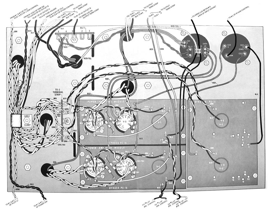
5 Installing the Capacitor EFB Board: 14 Using the supplied screws and lock washers, mount the Capacitor EFB board in place of the original twist lock cans in the orientation shown in Fig. below. Tighten all screws securely. Fig. 15 Solder a " length of #0- guage red wire to TS-1 terminal 4. Solder another " length of #0- guage red wire to TS-1 terminal 5 as shown in Fig. 4. Label the wires TS-1-4 and TS-1-5. Twist the wires together and route them along the back side of the chassis (behind the yellow, orange and black wires from the output transformer), and in the direction of the capacitor board Solder # 0- guage red wires to TS-1 terminals 4 and 5. Label these TS-1-4 and TS-1-5 Fig. 4 5
6 Preparing the PC-10 boards Refer to Fig. 5 for the following steps. Note: If your SCA-5 has previously been upgraded with Audio Regenesis PC-10A boards, follow the steps below paying attention to the *notes pertaining to the PC-10A. 16 Remove the wires connecting pin of V-6 to eyelet on the PC-10, and pin of V-5 to eyelet on the PC-10. *The wire connecting pin to eyelet will be a 10K resistor on the PC-10A. Leave the resistor in place. 1 Remove the wires connecting pin of V- to eyelet on the PC-10, and pin of V- to eyelet on the PC-10. *The wire connecting pin to eyelet will be a 10K resistor on the PC-10A. Leave the resistor in place. 1 Remove the red wire connecting pin of V-6 to pin of V-. 16 Remove these wires Remove this wire 1 1 Remove these wires Fig. 5 6

7 Preparing the PC-10 boards ctd. Refer to Fig. 6 for the following steps. 1 Remove the two wires connected to pin of V-6 and connect them to pin. Do not solder them yet. 0 Remove the wire connected to pin of V-5 and connect it to pin. Do not solder it yet. 1 Remove the two wires connected to pin of V- and connect them to pin. Do not solder them yet. Remove the wire connected to pin of V- and connect it to pin. Do not solder it yet. Note: Depending upon the excess length left by the original kit builder, it may be necessary to add length to the transformer wires connected to pin of sockets V-6 and V-. If required, be sure to properly insulate the connection where the join is made (heat shrink tubing, etc.). 1 Move these wires to pin V-6 Move this wire to pin 0 1 Move these wires to pin V- Move this wire to pin Fig. 6

8 Preparing the PC-10 boards ctd Connect and solder a new red wire to pin of socket V-. Route the wire as shown in fig. and label it as CATH RC. Connect a 100 ohm 0.5W resistor between pins and of socket V-6. Solder both pins. Connect a * 1K 0.5W resistor between pin of socket V-6 and eyelet on the PC-10. Solder both Connect a 1K 0.5W resistor between pin of socket V-5 and eyelet on the PC-10. Solder both connections. Connect a 100 ohm 0.5W resistor between pins and of socket V-5. Solder both pins. Connect a 100 ohm 0.5W resistor between pins and of socket V-. Solder both pins. Connect a * 1K 0.5W resistor between pin of socket V- and eyelet on the PC-10. Solder both Connect a 1K 0.5W resistor between pin of socket V- and eyelet on the PC-10. Solder both connections. Connect a 100 ohm 0.5W resistor between pins and of socket V-. Solder both pins. 4 * Note: If your SCA-5 has previously been upgraded with PC-10A output boards, these resistors will be 10K. Do not change them to 1K, leave them in place. * 5 6 When installing new PC-10A boards along with the EFB capacitor board be sure to use10k resistorsfor steps 5 and. The 1K resisitors shown apply to the stock PC-10 boards. * 0 1 Fig.

9 Wiring the Capacitor EFB Board Refer to Fig. and Fig. for the following steps: The following solder connections are made to the eyelets on the bottom side of the Capacitor EFB board. In preparation for inserting and soldering to the board eyelets, wires should be stripped back no more than 1/ and tinned. If the wires are stripped back too far they may contact components on the top side. Locate the two red wires previously labeled as C4-4. Insert the wires into the eyelets labeled C4 4 and solder. Locate the red wires from TS-1 previously labeled as TS-1-4 and TS-1-5. Trim these wires so that they will comfortably reach the eyelets labeled TS-1 4 and 5 on the capacitor board, but without too much excess. Solder them to eyelets TS-1 4 and 5. 4 Locate the red/yel wire previously labeled as C4-A. Insert the wire into one of the eyelets labeled C4 A-D and solder. These eyelets are all ground connections, so it doesn't really matter which one you choose. Note: the ground connections will require significant heat when soldering since they are connected directly to the PC board ground plane. 5 Locate the black wire previously labeled as C4-A. Insert the wire into one of the eyelets labeled C4 A-D and solder. 6 Locate the two black wires previously labeled as C4-C. Insert the wires into two of the eyelets labeled C4 A-D and solder. Locate the red wire previously labeled as CATH RC. Insert the wire into the eyelet labeled CATH RC and solder. Locate the red wire previously labeled as CATH LC. Insert the wire into the eyelet labeled CATH LC and solder. Locate the red wire previously labeled as C-. Insert the wire into the eyelet labeled C and solder. 40 Locate the red wire previously labeled as C-1. Insert the wire into eyelet C 1 and solder. 41 Locate the black wire previously labeled as C-D. Insert the wire into eyelet C D and solder. 4 Locate the black wire previously labeled as HUM. Insert the wire into eyelet HUM and solder. Note, in some cases it may be necessary to extend the length of the original wire. 4 C4-A red/yel C4-A black 5 HUM 4 C4-4 red C4-4 red TS-1-4 red TS-1-5 red C-D black 41 6 C4-C black C4-C black CATH RC red C- red CATH LC red 40 C-1 red Fig.
10 10 Fig.

11 The installation of your new Capacitor EFB board is now complete. At this point it is highly recommended that you carefully double check your wiring for errors. Also check the eyelets on the TOP side of the capacitor board to make sure that none of the wires coming through are touching any components. In particular, that wires coming through eyelets are not touching and melted to the plastic insulation of any of the electrolytic capacitors. Adjusting the Bias Current Before putting your SCA-5 back ito service, the bias current must first be correctly adjusted. In this regard, the EFB circuit is also unique in that only a single bias potentiometer is employed although there are two bias measurement test points, one for the common cathode connection of each channel. Adjusting the bias current involves setting the bias potentiometer such that the average of the voltages measured at the LC and RC test points is 0.VDC. For example, a reading of 0.VDC at the LC test point and 0.6VDC at the RC test point results in an average 0.VDC bias voltage. The 0.VDC bias voltage results in a bias current of ma vs 5mA for the stock circuit, lowering power dissipation and extending tube life. For best performance, and most balanced bias current, a well matched quad of output tubes should be installed. With old and/or mismatched output tubes, it may not be possible to achieve an average 0.VDC at the bias voltage test points. The values of the bias divider string for the EFB voltage regulator were intentionally chosen to result in the bias control potentiometer being well off center for most tubes when properly adjusted. This will prevent problems resulting from being able to adjust the grid bias voltage too low. However, it also means that worn out tubes, or tubes that are well off the mark with regards to bias requirements may not be able to be brought up to the correct current flow setting. A well matched quad of EL4 s, in good condition, should not present any problems in achieving the correct bias setting. HIGH VOLTAGE WARNING Extreme care must be exercised at all times when completing the following steps. High voltage will be present. If you are not certain of your ability to safely perform the following steps it is advised that you seek the services of a qualified technician. Refer to Fig. 10 for the following steps: Voltmeter Probes Fig. 10 Bias Potentiometer Test Sockets 4 Insert the negative probe of a digital voltmeter into test socket COM. Insert the positive probe into either test socket LC or RC. 44 Connect the power cord to an AC outlet and set the power switch to the Power on position. 45 Observe the reading on the voltmeter. Starting from cold, it will take approximately 15 seconds before the meter will begin to read, and the voltage will rise as the tubes warm up. After a minute or two, the reading should stabilize, then adjust the BIAS ADJ potentiometer for a reading of 0.VDC. 11
12 Adjusting the Bias Voltage Ctd. 46 Carefully move the positive voltmeter probe to the other test jack and observe the voltage reading. If it is very close to 0.VDC you need not make any further adjustment. If not, then adjust the BIAS ADJ potentiometer as required such that the average of the voltage readings taken at the LC and RC test points is 0.VDC. This may require taking several alternate readings between LC and RC test points while making small adjustments to the bias potentiometer. 4 After completing the bias adjustment, switch off the power and disconnect the AC power cord. The top cover can now be installed and your updated SCA-5 is ready to use. Operating Notes Ventilation: When using the SCA-5 it is essential that it have adequate ventilation, and this is especially important now that the solid state EFB regulator is installed within the amplifier. Although the regulator is an industrial rated component, with a very high rated operating temperature, and is mounted to a substantial heat sink, at best it can only run as cool as the interior ambient temperature of the SCA-5. Providing adequate ventilation will ensure that the regulator will always operate well below its rated maximum temperature, even at sustained full volume levels, and will provide long term reliable service. Never place anything directly on top of the cover when the amplifier is operating. There should always be several inches of air space above the unit and behind it. Do not remove the rubber mounting feet, or place the unit inside another type of enclosure (like a wood cabinet). The flow of air from above, and below, must never be restricted in any way or the intended cooling convection air flow will be impeded. Bias Voltage: It is desirable to check the bias voltage from time to time as it may change somewhat as the output tubes age. Repeat the steps under Adjusting the Bias Current and adjust the bias potentiometer as required. 1
13 R 0.1uF/ K 1W C 0. VDC 0.1uF/ LC RC C TM EFB Enhanced Fixed Bias COM K 1W 10uF/ CB 10uF/ CA 15K 1/W R5 R BIAS ADJ 10uF 50V 10 1/W 10 1/W 10 1/W 10 1/W K 1W 4uF/ P1 5K C4A C4D R1 R R R4 R40 10uF/ C4B 4uF/ C4C 4.uF 5V C4 LM VR1 D1 SCA-EFB-R01 1KV A D 1KV A 10K 1W 50 5W R6 0.1uF/ 10K 1W C1 R41 R D. Gillespie Designs SCA-5 Capacitor Board with EFB TM
14 C4 A-D C 0.1uF CA 10uF PC-11 HV C 1 5VDC R K 1W CB 10uF PC-10 1 HV C 5VDC R K 1W C 0.1uF K 1W C4A 4uF R40 PC-10 6BQ5 HV C4B 10uF C4 4 0VDC C1 0.1uF R41 50R 5W 400VDC C4C 4uF D1 1KV/A D 1KV/A TS VAC (GND) (GND) C D R 10R 0.5W 1% MF Test Jack LC VR1 LM IN OUT Test Jack COM R4 10R 0.5W 1% MF CATH LC ADJ C4 C4D 10uF 50V HUM 15VDC R1 10R Test Jack RC 0.5W 1% MF CATH RC 4.uF 5V R5 CW 1 R6 R R 10R 0.5W 1% MF 15K 0.5W P1 5K 0.5W Bias Adj. 10K 1W 10K 1W Note: DC voltages are relative to chassis ground. D. Gillespie Designs SCA-5 Capacitor Board with EFB TM
15 Figure-. Complete schematic of the SCA-5 modified with EFB. Additions are shown in red. PC-10 RIGHT CHANNEL C1 R 5 6 R0 V4 1 C1 R1 R 1 R C1 C0 R4 R5 R V 6BQ5 BIAS TP RC 6BQ5 V R R BLU/WH GRN/WH RED GRN BLU Z-565 YEL OR BLK 16 C 10 C R 1 TO EYELET 1 PC-11 C CA R C CB R R40 C4A C1 C4B IN VR1 OUT C4 ADJ C4D R6 R R5 P1 BIAS ADJ. R41 BIAS TP COM 4 C4C D1 RED RED/YEL GRN GRN WH A SLO BLO BLK C RED D BLK BRN VAC V V6 V5 V 4/5 4/ V 1 V V V BRN WH PA-4 CONNECT JUMPER OR CENTER SPEAKER PC-10 LEFT CHANNEL C1 R 5 6 R0 V4 1 C1 R1 R 1 R C1 C0 R4 R5 R V5 6BQ5 BIAS TP LC 6BQ5 V6 R1 R BLU/WH GRN/WH RED GRN BLU Z-565 YEL OR BLK 16 C C R 1 D. Gillespie Designs SCA-5 Capacitor Board with EFB TM
Mapletree Audio Design SR70A Special Red Driver Module for Dynaco ST-70
 Mapletree Audio Design S70A Special ed Driver Module for Dynaco ST-70 Installation instructions ev. Jan. 9/ The Special ed S70A driver module is a drop in replacement for the original driver board of the
DIY Tube Stereo 70 Board - TubeZone Assembled -Instructions - Page 1
 DIY Tube Stereo 70 Board - TubeZone Assembled -Instructions - Page 1 Board and portions of manual, (c) 2006 Shannon Parks & DIYtube.com. Version specific instructions (c) 2006 Ned Carlson and Tubezone.net
Dynaco MK3 Electrolytic Cap Upgrade Assembly, Installation, and Adjustment Manual
 Page 1 PC-M3U Rev 1 I. Introduction Thanks for your purchase of our Mark 3 Quad Electrolytic Capacitor Replacement Board PC-M3U. It has been designed to replace the original Dynaco Quad (4 section) Aluminum
SCA-35 System Capacitor Module Assembly & Instruction Manual
 SCA-35 System Capacitor Module Assembly & Instruction Manual I. Introduction Thank you for your purchase of our SCA35-CAP System Capacitor Module. It has been designed to replace both the power supply
Power Supply Board. by Classic Valve Design for the Dynaco Mark-III with failsafe bias and balance
 Power Supply Board by Classic Valve Design for the Dynaco Mark-III with failsafe bias and balance Classic Valve Design assumes no responsibility for circuit or user damage from the use or misuse of these
Step by Step Building PJ meter ARDF Receiver Kit. CRKITS.COM August 5, 2013
 Step by Step Building PJ-80 80-meter ARDF Receiver Kit CRKITS.COM August 5, 2013 What is ARDF? ARDF is the abbreviation of Amateur Radio Direction Finding, or so called Fox Hunting. If you are looking
Assembly and Installation Instructions for White Oak Audio Design TM-1001 LED board
 Thank you for purchasing White Oak Audio Design s TM-1001 Upgrade LED Light Board. White Oak Audio Design products are meticulously engineered and tested to ensure a direct drop in fit with your tuner.
Drawing 1 T14 T11 TR1 TR2 R(BIAS) T12 T13 T10 TOP REAR FRONT GROMMET 4 GROMMET 2 GROMMET 1 GROMMET 3 GROMMET 5 TR2 TR1 TR2 TR2 #6 #6 #6 #6 #10 #10 #10
 T12 T13 T10 TOP REAR FRONT GROMMET 4 GROMMET 2 GROMMET 1 GROMMET 3 GROMMET 5 TR2 TR1 TR2 TR2 #6 #6 #6 #6 #10 #10 #10") Drawing TOP REAR V V V V T T TR TR TR TR GROMMET SIDE GROMMET SIDE GROMMET TR TR TR GROMMET TR GROMMET T T T FRONT Drawing V V V V T T TR TR TR TR GROMMET GROMMET COLD HOT GROMMET TR TR TR GROMMET TR GROMMET
Drawing TOP REAR V V V V T T TR TR TR TR GROMMET SIDE GROMMET SIDE GROMMET TR TR TR GROMMET TR GROMMET T T T FRONT Drawing V V V V T T TR TR TR TR GROMMET GROMMET COLD HOT GROMMET TR TR TR GROMMET TR GROMMET
THE THUNDERDRIVE (K-950)
") THE THUNDERDRIVE (K-950) OUTPUT DISTORTION Unplug when not in use to save battery life. TO AMP IN The Thunderdrive Modkitsdiy.com FROM GUITAR OUT Use these instructions to learn: How to build an effects
THE THUNDERDRIVE (K-950) OUTPUT DISTORTION Unplug when not in use to save battery life. TO AMP IN The Thunderdrive Modkitsdiy.com FROM GUITAR OUT Use these instructions to learn: How to build an effects
Building a Bitx20 Version 3
 Building a Bitx20 Version 3 The board can be broken into sections and then built and tested one section at a time. This will make troubleshooting easier as any problems will be confined to one small section.
INSTRUCTIONS FOR ASSEMBLY AND OPERATION
 diytube stereo 0 driver board INSTRUCTIONS FOR ASSEMBLY AND OPERATION Price $0.00 Important Note: The phase is swapped on the diytube ST0 from the orginal design. Be sure to hook up the drive lines (at
DIODE / TRANSISTOR TESTER KIT
 DIODE / TRANSISTOR TESTER KIT MODEL DT-100K Assembly and Instruction Manual Elenco Electronics, Inc. Copyright 1988 Elenco Electronics, Inc. Revised 2002 REV-K 753110 DT-100 PARTS LIST If you are a student,
Instructions MODIFICATION KIT MODEL SBM - 1O2-1 INTRODUCTION PARTS LIST FOR THE
 Instructions FOR THE MODIFICATION KIT MODEL SBM - 1O2-1 INTRODUCTION This modification Kit applies to the following Heath Transceivers: 1. All Models HW-100, SB-100, SB-101 and SB-101W. 2. Any Model SB-102
Assembly Instructions for the 1.5 Watt Amplifier Kit
 Assembly Instructions for the 1.5 Watt Amplifier Kit 1.) All of the small parts are attached to a sheet of paper indicating both their value and id. 2.) Leave the parts affixed to the paper until you are
1. Summary. 15/08/2009 Philips Valve Amplifier Type LBH1015/01 Page 1 of 7. Valve PA Amplifier. Philips label Model Code LBH1015/01 Serial No 1080
 15/08/2009 Philips Valve Amplifier Type LBH1015/01 Page 1 of 7 1. Summary Valve PA Amplifier. Philips label Model Code LBH1015/01 Serial No 1080 Two input, mono 60W amplifier with tone control and 50V/70V/100V
Build an All-Tube Fuzz/Wah Pedal
 Build an All-Tube Fuzz/Wah Pedal by Eric Barbour and Peter Belov In spite of more than 30 years of development and marketing, to this day all commercial guitar "wah" pedals have been solid- state and have
BRIDGE MODE FOR THE STEREO 120. Preface to Everything PLEASE READ THIS FIRST! YOU MAY SAVE YOURSELF A LOT OF TROUBLE!
 BRIDGE MODE FOR THE STEREO 120 Preface to Everything PLEASE READ THIS FIRST! YOU MAY SAVE YOURSELF A LOT OF TROUBLE! At some point I made 4 Ohm 1 khz output power tests of single channels of the updated
PM24 Installation Instructions
 Marchand Electronics Inc. PO Box 473, Webster, NY 14580 Tel:(716) 872-0980 Fax:(716) 872-1960 info@marchandelec.com http://www.marchandelec.com (c)1997 Marchand Electronics Inc. PM24 Installation Instructions
PM124 Installation Instructions. See important note about revisions of this board on the last page.
 Marchand Electronics Inc. PO Box 473, Webster, NY 14580 Tel:(716) 872-0980 Fax:(716) 872-1960 info@marchandelec.com http://www.marchandelec.com (c)1997 Marchand Electronics Inc. PM124 Installation Instructions
Specimen Products Single Ended Stereo Amp Instruction Book
 Specimen Products Single Ended Stereo Amp Instruction Book Specimen tube amplifier designs are informed by decades of servicing and building musical instrument amps. As a result of being subjected to the
Pacific Antenna Easy Transmitter Kit
 Pacific Antenna Easy Transmitter Kit Introduction The Easy Transmitter kit from qrpkits.com provides a crystal controlled transmitter with VXO tuning. The circuit consists of a N3904 based crystal oscillator
Balanced Modulator. Model 9748 Assembly and Using Manual PAiA Corporation
 Balanced Modulator Model 9748 Assembly and Using Manual This second-generation 9700-series processing element for modular sound synthesizers is designed to provide great sound and excellent value. Audio
Manual AMERITRON QSK-5PC T/R SWITCH PC BOARD INTRODUCTION
 Manual Instruction AMERITRON QSK-5PC T/R SWITCH PC BOARD INTRODUCTION The Ameritron QSK-5PC is a PIN diode QSK circuit board designed for use in Ameritron's AL-80A, AL-80B, AL-82, AL-1500 and AL- 1200
ABC V1.0 ASSEMBLY IMPORTANT!
 ABC V1.0 ASSEMBLY Before starting this kit, prepare the following tools: Soldering iron (15-20W will do), flush cutters, no.2 hex screwdriver or allen key and phillips screwdriver. Also briefly go through
Project 747 VERSION 1.3 USER MANUAL February 22nd 2018
 VERSION 1.3 USER MANUAL February 22nd 2018 WWW.GARAGE1217.COM WARNING: Project requires knowledge of AC electrical systems, repair of said systems and restoration of said systems. If proper safety measures
SCHEMATIC OF GRAYMARK 808 POWERED BREADBOARD
 SCHEMATIC OF GRAYMARK 808 POWERED BREADBOARD 1a white SW1 white 2a TP1 blue TP2 black blue TP3 TP4 yellow TP5 yellow TP6 4 3 8 7 + D1 D2 D5 D6 C1 R1 TP8 Q1 R3 TP12 2 TP18 U2-0-15V C8 9 C2 + TP15 C5 R12
Jason Stull. Physics 498 (Physics of Music) Valve Junior Modification 5/13/2010
 Valve Junior Modification 5/13/2010") Jason Stull Physics 498 (Physics of Music) Valve Junior Modification 5/13/2010 1 Introduction My original idea for a class project was to build a tube guitar amplifier. I have wanted a tube amp for some
Jason Stull Physics 498 (Physics of Music) Valve Junior Modification 5/13/2010 1 Introduction My original idea for a class project was to build a tube guitar amplifier. I have wanted a tube amp for some
PAT-4 POWER SUPPLY ASSEMBLY MANUAL Rev B Version
 PAT-4 POWER SUPPLY ASSEMBLY MANUAL Rev B Version 2013 AkitikA, LLC All rights reserved Revision Bp01 November 3, 2013 Page 1 of 16 Table of Contents Table of Contents... 2 Table of Figures... 2 Section
Bill of Materials: PWM Stepper Motor Driver PART NO
 PWM Stepper Motor Driver PART NO. 2183816 Control a stepper motor using this circuit and a servo PWM signal from an R/C controller, arduino, or microcontroller. Onboard circuitry limits winding current,
LBI-4938C. Mobile Communications MASTR II POWER AMPLIFIER MODELS 4EF4A1,2,3. Printed in U.S.A. Maintenance Manual
 C Mobile Communications MASTR II POWER AMPLIFIER MODELS 4EF4A1,2,3 Printed in U.S.A. Maintenance Manual TABLE OF CONTENTS DESCRIPTION.................................................... 1 CIRCUIT ANALYSIS.................................................
SERVICE MANUAL 2 CHANNEL POWER AMPLIFIER GFA-5400
 SERVICE MANUAL 2 CHANNEL POWER AMPLIFIER GFA-5400 TABLE OF CONTENTS Introduction...1 Version 1 vs. Version 2........ 1 Test Procedures............. 1 Parts List...2 Specifications...6 Chassis Layout...............
IPR LA-3 KIT last update 15 march 06
 IPR LA-3 KIT last update 15 march 06 PART-2: Audio Circuitry CIRCUIT BOARD LAYOUT: Power and Ground Distribution Now that your power supply is functional, it s time to think about how that power will be
BrewsBySmith.com STC DIY Kit
 BrewsBySmith.com STC-1000 + DIY Kit Contact Information: Greg Smith www.brewsbysmith.com greg@boostbysmith.com I. Hardware Included: STC-1000 flashed with latest software (v1.06 currently) (if purchased)
1.1 Original Amplifier Professional construction well made. No markings. Based on R&H Feb Watt Amplifier.
 4/03/2018 Australian 5W Combo Page 1 of 6 1. Summary Combo 5W Valve Amplifier and 8 Rola speaker. Unknown maker., Dec 2017. 1.1 Original Amplifier Professional construction well made. No markings. Based
Assembly Instructions for the FRB FET FM 70 Watt Amp
 Assembly Instructions for the FRB FET FM 70 Watt Amp 1.) Orient the circuit board with the diagram 2.) Use a narrow chisel tip 25-30 watt soldering iron for assembly 3.) All the small parts are taped onto
Grounded Grid Plus Vacuum Tube Preamplifier User Manual. Analog Metric
 Grounded Grid Plus Vacuum Tube Preamplifier User Manual Analog Metric Page 2 INTRODUCTION This Grounded Grid Plus preamplifier provides enhanced performance out of the original Grounded Grid design. This
Telecaster Wiring Kits Please Read All Instructions Before Beginning. Tools you will need: Soldering tips: Removing Current Wiring: Step 1. Step 2.
 Telecaster Wiring Kits Please Read All Instructions Before Beginning. Tools you will need: Soldering Iron (35 watt preferably) Solder Wet Sponge Wire Clippers Wire Strippers 3/8 Drill Bit 5/32 Drill Bit
THE RING RESONATOR (K-975)
") THE RING RESONATOR (K-975) OUTPUT BOOST The Ring Resonator An Octave Up Fuzz Modkitsdiy.com 9 VDC CENTER (-) ADAPTER TO AMP IN FROM GUITAR OUT Unplug when not in use to save battery life. Use these instructions
THE RING RESONATOR (K-975) OUTPUT BOOST The Ring Resonator An Octave Up Fuzz Modkitsdiy.com 9 VDC CENTER (-) ADAPTER TO AMP IN FROM GUITAR OUT Unplug when not in use to save battery life. Use these instructions
SoftRock v6.0 Builder s Notes. May 22, 2006
 SoftRock v6.0 Builder s Notes May 22, 2006 Be sure to use a grounded tip soldering iron in building the v6.0 SoftRock circuit board. The soldering iron needs to have a small tip, (0.05-0.1 inch diameter),
Assembly Manual V1R2B-Rev1.0D
 Assembly Manual V1R2B-Rev1.0D for 4 State QRP MagicBox - Solid State Transmit/Receive System Designed by: Jim Kortge, K8IQY Copyright 2009-2012 - All rights reserved This system is the result of some brainstorming
The Wave (K-MOD103) GUITAR DWELL REVERB REVERB SWITCH ON OUT OFF
 GUITAR DWELL REVERB REVERB SWITCH ON OUT OFF") The Wave (K-MOD103) OUT IN GUITAR IN DWELL REVERB REVERB SWITCH ON GUITAR OUT POWER ON OFF OFF Please note, there are no labels for this kit. The controls, switches and connectors have only been labeled
The Wave (K-MOD103) OUT IN GUITAR IN DWELL REVERB REVERB SWITCH ON GUITAR OUT POWER ON OFF OFF Please note, there are no labels for this kit. The controls, switches and connectors have only been labeled
Mini Block Ultra Linear Class A Push-Pull Valve Power Amplifier
 Mini Block Ultra Linear Class A Push-Pull Valve Power Amplifier Precaution: This project uses potentially lethal voltages and should not be undertaken by anyone who is not familiar with working with such
(K-MOD102) TROUBLESHOOTING SUPPLEMENT
 TROUBLESHOOTING SUPPLEMENT") (K-MOD0) TROUBLESHOOTING SUPPLEMENT ON BASS TREBLE VOLUME OFF MOD 0 TUBE AMP KIT Use this supplement to help: Measure voltage test points to identify major discrepancies and locate problem areas. (Keep
(K-MOD0) TROUBLESHOOTING SUPPLEMENT ON BASS TREBLE VOLUME OFF MOD 0 TUBE AMP KIT Use this supplement to help: Measure voltage test points to identify major discrepancies and locate problem areas. (Keep
Line-Following Robot
 1 Line-Following Robot Printed Circuit Board Assembly Jeffrey La Favre October 5, 2014 After you have learned to solder, you are ready to start the assembly of your robot. The assembly will be divided
DIODE / TRANSISTOR TESTER KIT
 DIODE / TRANSISTOR TESTER KIT MODEL DT-100K 99 Washington Street Melrose, MA 02176 Phone 781-665-1400 Toll Free 1-800-517-8431 Visit us at www.testequipmentdepot.com Assembly and Instruction Manual Elenco
the DON classics U76 (blue face - rev A) ASSEMBLY GUIDE REV: 1:04
 ASSEMBLY GUIDE REV: 1:04") the DON classics www.thedonclassics.com U76 (blue face - rev A) ASSEMBLY GUIDE REV: 1:04 QUICK ASSEMBLY GUIDE 9 STEPS TO COMPRESSOR HEAVEN! 1. 2. 3. 4. 5. 6. 7. 8. 9. Solder parts on PCB Wire pots Solder
the DON classics www.thedonclassics.com U76 (blue face - rev A) ASSEMBLY GUIDE REV: 1:04 QUICK ASSEMBLY GUIDE 9 STEPS TO COMPRESSOR HEAVEN! 1. 2. 3. 4. 5. 6. 7. 8. 9. Solder parts on PCB Wire pots Solder
2 Recommended Tools / Supplies
 Bias Scout TM Kit Assembly Manual Version 3.1 25 March 2015 1 Inventory of Parts 1 ea octal socket 1 ea octal base, brown (1 3/16" dia x 7/8" high) 1 ea 1.0 / 1W metal oxide, flame proof resistor 1 ea
INTERNATIONAL RADIO CORP
 I N R A D INTERNATIONAL RADIO CORP 13620 Tyee Road Umpqua, OR 97486 (541) 459-5623 fax (541) 459 5632 E-mail: inrad@rosenet.net www.qth.com/inrad IC-775 ROOFING FILTER INSTALLATION INSTRUCTIONS The IC-775
Ten Tec DDS Board Assembly Procedure
 05 May 2014 Ten Tec DDS Board Assembly Procedure You will find a photo of a completed board at the end of these instructions. Refer it whenever clarification is required. 1. AD9835 Attachment If you purchased
Manual Version July 2007
 Manual Version 1.2 - July 2007 Page 1 Table of Contents Section1: M3 Phono Board Build...3 Phono Board Parts List...3 Preparation...4 Fitting the Valve Bases...6 Installing the Resistors...7 Starting the
MC24O OWNER'S MANUAL STEREO POWER AMPLIFIER CONTENTS
 STEREO POWER AMPLIFIER MC24O CONTENTS GENERAL DESCRIPTION 1 TECHNICAL DESCRIPTION 1 PANEL FACILITIES 4 INSTALLATION 5 CONNECTIONS 5 Input Stereo 5 Input Twin Amp 5 Input Mono 6 Output Stereo or Twin Amp
Assembly and Installation Instructions for White Oak Audio Design PL400 Series 1 LED board
 Thank you for purchasing White Oak Audio Design s Phase Linear PL400 Upgrade LED Light Board. White Oak Audio Design products are meticulously engineered and tested to ensure a direct drop in fit with
Classic Valve Design
 DynaMull Driver Board for the Dynaco ST-70 Classic Valve Design Classic Valve Design assumes no responsibility for circuit or user damage from the use or misuse of these boards or any other product. We
Read This Page First
 Read This Page First If you are reading this you know the manuals are always available at QRPKITS.com. This is version 8.0 of the manual dated 4/27/2016. There is no need to print out the whole assembly
Step 3. Remove the strings from your guitar.
 VSTK-1 Vintage Stratocaster Kit Please Read All Instructions Before Beginning. Tools you will need: Soldering Iron (35 watt preferably) Solder Wet Sponge Wire Clippers Electric Drill 3/16 Drill Bit 11/64
PRICE $2.00 MODEL PA500M* AMPLIFIER SERVICE MANUAL
 PRICE $2.00 MODEL PA500M* AMPLIFIER SERVICE MANUAL SECTION I GENERAL DESCRIPTION The standard operating functions of this siren are Wail, Tap II, Yelp and manual peak-and-hold. The Tap II feature allows
A 75-Watt Transmitter for 3 Bands Simplified Shielding and Filtering for TVI BY DONALD H. MIX, W1TS ARRL Handbook 1953 and QST, October 1951
 A 75-Watt Transmitter for 3 Bands Simplified Shielding and Filtering for TVI BY DONALD H. MIX, W1TS ARRL Handbook 1953 and QST, October 1951 The transmitter shown in the photographs is a 3-stage 75-watt
S-Pixie QRP Kit. Student Manual. Revision V 1-0
 S-Pixie QRP Kit Student Manual Revision V 1-0 Introduction The Pixie 2 is a small, versatile radio transceiver that is very popular with QRP (low power) amateur radio operators the world over. It reflects
PowerAmp Design. PowerAmp Design EVAL189 EVALUATION KIT FOR MODEL PAD189. Rev B
 PowerAmp Design EVALUATION KIT FOR MODEL PAD189 Rev B INTRODUCTION The evaluation kit provides a convenient method to become familiar with the operation of amplifier model PAD189 before your application
Build Your Own Clone Mouse Kit Instructions
 Build Your Own Clone Mouse Kit Instructions Warranty: BYOC, Inc. guarantees that your kit will be complete and that all parts and components will arrive as described, functioning and free of defect. Soldering,
DIGITAL / ANALOG TRAINER
 DIGITAL / ANALOG TRAINER MODEL XK-150 A COMPLETE MINI-LAB FOR BUILDING, TESTING AND PROTOTYPING ANALOG AND DIGITAL CIRCUITS Instruction Manual ELENCO Copyright 2016, 1998 by ELENCO Electronics, Inc. All
THE AGGRESSOR (K-995)
") THE AGGRESSOR (K-99) TONE VOLUME DISTORTION MID-SHIFT SWITCH LED The Aggressor Distortion Pedal Modkitsdiy.com 9 VDC CENTER (-) ADAPTER TO AMP IN FROM GUITAR OUT Unplug when not in use to save battery
THE AGGRESSOR (K-99) TONE VOLUME DISTORTION MID-SHIFT SWITCH LED The Aggressor Distortion Pedal Modkitsdiy.com 9 VDC CENTER (-) ADAPTER TO AMP IN FROM GUITAR OUT Unplug when not in use to save battery
HAMTRONICS TB901 FM EXCITER INSTALLATION, OPERATION, & MAINTENANCE
 HAMTRONICS TB901 FM EXCITER INSTALLATION, OPERATION, & MAINTENANCE GENERAL INFORMATION. The TB901 is a single-channel low power fm transmitter (exciter) designed to provide 300-600 milliwatts continuous
CONSTRUCTION. Refer to schematic and component location diagrams during assembly
 HAMTRONICS VHF RECEIVING CONVERTERS CONSTRUCTION, ALIGNMENT, & INSTALLATION INSTRUCTIONS GENERAL DESCRIPTION. The CA( ) series of VHF Receiving Converter modules are designed to amplify and convert the
Pacific Antenna Field Strength Indicator Kit
 Pacific Antenna Field Strength Indicator Kit Description The Field Strength Indicator kit from Pacific Antenna provides a visual way to monitor the presence and relative strength RF fields through the
The 6LE8 One Tube Broadcaster
 The 6LE8 One Tube Broadcaster Introduction The purpose of this broadcaster is to transmit your favorite music to every AM radio in your home. The transmitting power is so low that it should not bother
FUNCTION GENERATOR KIT
 FUNCTION GENERATOR KIT MODEL FG-500K Assembly and Instruction Manual Elenco Electronics, Inc. Copyright 2005 by Elenco Electronics, Inc. All rights reserved. Revised 2005 REV-B 753069 No part of this book
THE STEP LADDER (K-978)
") THE STEP LADDER (K-978) Footswitch True-bypass = 0 db OUTPUT INPUT Ground shunt switching on the input jack keeps the amp quiet when unplugged from the Step Ladder. Attenuator Pot Full clockwise = 0 db
THE STEP LADDER (K-978) Footswitch True-bypass = 0 db OUTPUT INPUT Ground shunt switching on the input jack keeps the amp quiet when unplugged from the Step Ladder. Attenuator Pot Full clockwise = 0 db
AM/FM RADIO KIT MODEL AM/FM-108K INTEGRAL CIRCUIT, 9 TRANSISTORS, 4 DIODES. Assembly and Instruction Manual
 AM/FM RADIO KIT MODEL AM/FM-108K INTEGRAL CIRCUIT, 9 TRANSISTORS, 4 DIODES Assembly and Instruction Manual TM Elenco Electronics, Inc. Copyright 2003, 1989 by Elenco TM Electronics, Inc. All rights reserved.
FROM: Apply +15V to the HV SAMPLE terminal on the self-resonant board. Verify that the red LED, D6 (HV Charge) is illuminated on the display board.
 is illuminated on the display board.") The following document outlines the known errors and omissions in the minibrute DRSSTC design. These include both the book, DRSSTC: Building the Modern Day Tesla Coil minibrute Reference Design as well
The following document outlines the known errors and omissions in the minibrute DRSSTC design. These include both the book, DRSSTC: Building the Modern Day Tesla Coil minibrute Reference Design as well
Instructions for Building the Pulsed Width Modulation Circuit. MC-12 (DC Motor Controller or PWM) From Electronic Light Inc. (revised kit 8/08)
 From Electronic Light Inc. (revised kit 8/08)") Instructions for Building the Pulsed Width Modulation Circuit MC-12 (DC Motor Controller or PWM) From Electronic Light Inc. (revised kit 8/08) Using this circuit for a pulsed DC current to your cell. Do
Instructions for Building the Pulsed Width Modulation Circuit MC-12 (DC Motor Controller or PWM) From Electronic Light Inc. (revised kit 8/08) Using this circuit for a pulsed DC current to your cell. Do
QUICKSILVER MX-190 OPERATING INSTRUCTIONS ,,-
 QUICKSILVER MX-190 OPERATING INSTRUCTIONS -------..,,- INPUT CONNECTIONS To maintain a short and concise signal path, the input connectors are mounted directly on the plug-in front-end circuit boards.
The Tellun Corporation. TLN-861 Dunsel. User Guide, Rev Scott Juskiw The Tellun Corporation
 The Tellun Corporation TLN-861 Dunsel User Guide, Rev. 1.0 Scott Juskiw The Tellun Corporation scott@tellun.com TLN-861 User Guide Revision 1.0 August 31, 2006 1. Introduction The TLN-861 Dunsel is a collection
AC/DC POWER SUPPLY KIT
 AC/DC POWER SUPPLY KIT MODEL K-11 Assembly and Instruction Manual ELENCO Copyright 2016, 1989 by ELENCO All rights reserved. Revised 2016 REV-O 753211 No part of this book shall be reproduced by any means;
Thank you very much for choosing Shuguang Audio Classic Series vacuum tube amplifier
 Thank you very much for choosing Shuguang Audio Classic Series vacuum tube amplifier (845 version). When opening the package, please carefully unpack all tubes and install each tube to its marked location
Modifying The Heath HA-14 For 6 Meters Greg Chartrand - W7MY 4/22/07
 Introduction The Heathkit HA-14 was one of the few electron tube linear amplifiers intended for mobile use but few were purchased with the 12 volt mobile power supply. Most hams bought the HA-14 for base
Instructions for Building the Pulsed Width Modulation Circuit. MC-12 (DC Motor Controller or PWM) From Electronic Light Inc. (revised kit 10/03/08)
 From Electronic Light Inc. (revised kit 10/03/08)") Instructions for Building the Pulsed Width Modulation Circuit MC-12 (DC Motor Controller or PWM) From Electronic Light Inc. (revised kit 10/03/08) Congratulations on your purchase of the MC-12 DC Motor
Instructions for Building the Pulsed Width Modulation Circuit MC-12 (DC Motor Controller or PWM) From Electronic Light Inc. (revised kit 10/03/08) Congratulations on your purchase of the MC-12 DC Motor
HT-1A Dual Band CW QRP Transceiver. Kit Building Instructions
 HT-A Dual Band CW QRP Transceiver Kit Building Instructions Rev B, July 8, 08 Designed by BD4RG Exclusively distributed by CRKITS.COM and its worldwide distributors Join the group http://groups.io/g/crkits
LM2405 Monolithic Triple 7 ns CRT Driver
 LM2405 Monolithic Triple 7 ns CRT Driver General Description The LM2405 is an integrated high voltage CRT driver circuit designed for use in color monitor applications The IC contains three high input
Dual CV Source + Attenuator/Mixer
 Dual CV Source + Attenuator/Mixer Model 9744 Assembly and Using Manual This second-generation 9700-series processing element for modular sound synthesizers is designed to provide great sound and excellent
Marchand Electronics Inc
 . PO Box 8099, Rochester NY 8 Tel:(585) 3 0 Fax:(585) 3 9375 info@marchandelec.com www.marchandelec.com (c)00. MB Push-pull tube amplifier www.marchandelec.com 585 3 0 Parts List A section R R R3 R R5
SIMPLE DIRECT DRIVE DESULPHATOR/ DESULFATOR KIT INSTRUCTIONS
 SIMPLE DIRECT DRIVE DESULPHATOR/ DESULFATOR KIT INSTRUCTIONS Parts List C1 470uF/ 25V 1off C2 C5 0.1uF/ 50V 4off C6 C9 0.01uF/ 50V 4off D1 12V/ 1.3W zener 1off Q1 2N2907 1off Q2 Q4 IRFB3307 3off R1 510R/
The Walford Electronics Ford Receiver Kit Project Construction Manual
 The Walford Electronics Ford Receiver Kit Project Construction Manual Walford Electronics Ford Receiver construction manual V1.5 Page 1 of 22 Introduction The Ford receiver has four stages: The first stage
Cornet2 Phonostage Kit Manual
 HAGERMAN T E C H N O L O G Y Cornet2 Phonostage Kit Manual Cornet2 Phonostage Kit Manual 2 Warnings This product uses dangerous and potentially lethal voltages. Extreme care must be taken while assembling
The Uniden Grant XL Owners Site
 The Uniden Grant XL Owners Site Modifications page for the Grant XL (For Informational purposes only) The author of this site takes NO responsibility for illegal modifications and/or use of illegally modified
THE TRILL TREMOLO (K-960)
") THE TRILL TREMOLO (K-60) DEPTH SPEED The Trill Tremolo Modkitsdiy.com Unplug when not in use to save battery life. TO AMP IN FROM GUITAR OUT Use these instructions to learn: How to build an effects pedal
THE TRILL TREMOLO (K-60) DEPTH SPEED The Trill Tremolo Modkitsdiy.com Unplug when not in use to save battery life. TO AMP IN FROM GUITAR OUT Use these instructions to learn: How to build an effects pedal
WHISTLE ROCK AUDIO ML12 PSU KIT/PCB
 WHISTLE ROCK AUDIO ML12 PSU KIT/PCB TABLE OF CONTENTS 1. INTRODUCTION Page 3 2. BILL OF MATERIAL Page 4 3. ALTERNATE RESISTOR VALUES Page 5 4. ASSEMBLY GUIDE Page 6 to 11 5. CONNECTIONS Page 12 6. SETUP
CW-ADD. Universal CW Adapter for SSB Transceivers. Assembly manual. Last updated: October 1,
 CW-ADD Universal CW Adapter for SSB Transceivers Assembly manual Last updated: October 1, 2017 ea3gcy@gmail.com Updates and news at: www.ea3gcy.com Thanks for building the Universal CW Adapter kit CW-ADD
OV4 DYNAMIC INTELLIGENT VALVE OPTIMIZATION (DIVO) INSTALL GUIDE
 INSTALL GUIDE") DYNAMIC INTELLIGENT VALVE OPTIMIZATION (DIVO) INSTALL GUIDE 1 CONTACT DETAILS Orange Amplifiers OMEC House 108 Ripon Way Borehamwood Hertfordshire WD6 2JA ENGLAND Tel: +44 20 8905 2828 Fax: +44 20 8905
DYNAMIC INTELLIGENT VALVE OPTIMIZATION (DIVO) INSTALL GUIDE 1 CONTACT DETAILS Orange Amplifiers OMEC House 108 Ripon Way Borehamwood Hertfordshire WD6 2JA ENGLAND Tel: +44 20 8905 2828 Fax: +44 20 8905
Starving Student II. Starving Student II. SS2 guide. Written By: 6L guides.diyaudio.com/ Page 1 of 24
 SS2 guide Written By: 6L6 2019 guides.diyaudio.com/ Page 1 of 24 INTRODUCTION This is a build guide for the hybrid headphone/pre-amplifier. You can buy a kit at the SSII product listing on the diyaudio
Pacific Antenna Wall Wart Tamer 2.0 Kit
 Pacific Antenna Wall Wart Tamer 2.0 Kit Description The Wall Wart Tamer lets you utilize those surplus computer and wall pack power supplies as a clean, adjustable voltage, DC power source for radios and
Bitx Version 3 Linear Amplifier Assembly
 Bitx Version 3 Linear Amplifier Assembly The power supply section has 2 options. 1 - AC input and a higher voltage on the IRF510 and +12 volts to the bitx. 2 - +12 volts applied to both the final and the
Ameritron ALS-600 Retrofit ALS-600-LPF Assembly Manual
 Ameritron ALS-600 Retrofit ALS-600-LPF Assembly Manual FEATURES Automatic band change based on TX frequency. PIN diode QSK RX/TX switch. Temperature controlled FAN for quiet operation. RS-232 serial port
LITTLE NERD v1.1 Assembly Guide
 last update: 9. 3. 2016 LITTLE NERD v1.1 Assembly Guide bastl instruments.com INTRODUCTION This guide is for building Little Nerd module from Bastl Instruments. It is good to have basic soldering skills
Mono Amplifier. LM386 Headphone Amp
 Mono Amplifier LM386 Headphone Amp Layout On/Off Switch - cuts power to the circuit Mono Input Jack: use either L or R or solder together Schematic Step 1 - Parts List 1.) R1-10ohm Resistor - Brown Black
Assembly and Installation Instructions for White Oak Audio Design PL700B LED board
 Thank you for purchasing White Oak Audio Design s Phase Linear PL700B Upgrade LED Light Board. White Oak Audio Design products are meticulously engineered and tested to ensure a direct drop in fit with
INSTRUCTIONS FOR ASSEMBLY OPERATION
 diytube stereo power amplifier rev c INSTRUCTIONS FOR ASSEMBLY OPERATION Price $0.00 Disclaimer Under no circumstances does diytube assume liability or responsibility for injury or damages sustained in
Assembly Instructions
 Assembly Instructions For the SSQ-2F 3.1 MHz Rife Controller Board Kit v1.41 Manual v1.00 2012 by Ralph Hartwell Spectrotek Services GENERAL ASSEMBLY INSTRUCTIONS Arrange for a clean work surface with
KLD Guitar AMP MOJO12HR
 KLD Guitar AMP MOJO12HR TMB-18H Tube Guitar Amplifier Manual Kailing Electronic Co.,Ltd http://www.kldguitar.com Intended to alert the user to the presence of un-insulated dangerous voltage within the
Wiring Manual NEScaf April 2010 (August 2006)
") Wiring Manual NEScaf April 2010 (August 2006) Switched Capacitor Audio Filter The NEScaf is a switched capacitor audio filter (acronym SCAF) built around a building-block type filter chip. The NEScaf will
Wiring Manual NEScaf April 2010 (August 2006) Switched Capacitor Audio Filter The NEScaf is a switched capacitor audio filter (acronym SCAF) built around a building-block type filter chip. The NEScaf will