2. Solve this binary equation. Answer in a decimal number form = A. 42 B. 54 C. 15 D
|
|
|
- Colleen Hodges
- 5 years ago
- Views:
Transcription
1 Electronics Practice Test By David Scott, Manfred Brancard and Gary Troutman 1. A few capacitors are in parallel. Calculate the total capacitance. The capacitor values are 1uF, 2uF, 3uF, and 4uF. The total capacitance is: A. 10 uf B. 5 uf C. 1 uf D..01 uf 2. Solve this binary equation. Answer in a decimal number form = A. 42 B. 54 C. 15 D An Oscilloscope reads 10 volts peak to peak. What is the RMS voltage? A..707 VRMS B VRMS C VRMS D VRMS 4. In a capacitive circuit: A. Voltage leads current by 180 degrees B. Current leads voltage by 90 degrees C. Voltage leads current by 90 degrees D. Current leads voltage by 180 degrees 5. A heating element in an infant incubator uses 90 Watts of power and has a resistance of 1 kω. Calculate the current through the heating element. A..09 milliamps B..300 Milliamps C. 300 milliamps D. 9 milliamps 6. A Triac is used to switch A. DC power B. AC power C. AC or DC power D. FET gate current 7. Waveforms on an EEG Monitor are temporarily stored in: A. ROM B. RAM C. EPROM D. EEPROM 8. A GFCI normally has a trip point of A. 2 ma B. 3 ma C. 4 ma D. 6 ma 9. The IEEE standard for Ethernet communication: A B C D
 and the input current is 1 amp. Output current is? A. 250 ma B. 4 A C.")
2 10. Which one of these has the longest wavelength in the light spectrum: A. Violet Light B. Yellowish-Green Light C. Orange Light D. Dark Red Light 11. A Nicad battery normally has: A. 1.3 V per cell B. 1.2 V per cell C. 1.5 V per cell D. 1.0 V per cell 12. A transformer has 1968 primary windings and 492 secondary windings (4:1) and the input current is 1 amp. Output current is? A. 250 ma B. 4 A C. 500 ma D. 2 A 13. Calculate the total resistance of these resistors in parallel. 100 ohm, 3K ohm, 10K ohm. A ohms B ohms C. 95 ohms D. 100 ohms 14. Convert this number to decimal 4AF. A B C D What would the inputs have to be on a 3 input OR gate to get a low out? A. All low B. All high C. 2 lows 1 high D. 2 high 1 low


3 16. What inputs would be needed on the gate above to get a low output? A. high and high B. low and low C. low and high D. it can t have a low output 17. Checking a good transistor with a digital multimeter between C & E, it should read= A. 2 shorts B. 2 opens C..7V D. Short and open 18. Calculate the total inductance of two 40mH inductors in parallel. A. 20 mh B. 80 mh C. 40 mh D. 60mH 19. If a 4AH battery were replaced with a 2 AH with the same voltage rating, what would the result be? A. Shorter run time. B. Longer run time C. Same run time D.It would overheat the charging circuit 20. What type of filter is this? A. High Pass B. Low Pass C. Band Pass D. Impedance matching

4 The above circuit gives the normal operating voltages. Answer questions below using the above schematic drawing. 21. If VE= 40mVolts, VC=12 Volts, VB 700 mvolts. What is the defect? a. Open transistor base to emitter b. Open transistor collector to emitter c. Open transistor collector to base d. R2 is open 22. If VB=.105 volts, VC= 12 volts, VE=.105 in the circuit above, what is the defect? a. Open transistor base to emitter b. Shorted transistor base to emitter c. Open transistor collector to base d. C3 is open 23. If VB= 0.69 Volts, VE= 3 mv, VC= 3.2 V in the circuit above, what is the defect? a. Shorted C3 b. Open collector c. Open R1 d. Shorted R3 24. The normal output voltage at R5 is 550 mv peak. If the output voltage is only 250 mv, but the DC voltages at the transistor leads are normal, what is the defect? a. Open collector emitter of the transistor b. Leaky C3 c. Shorted R1 d. Open C2


5 25. What kind of amplifier set up is this in the drawing above? a. Common Collector b. Common Base c. Common Emitter d. Gate follower A. B.


6 C. D. E.

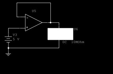
7 F. Please use the drawings above for questions Which drawing is a comparator a. A b. B c. C d. D e. E f. F 27. Which one of the drawings is a voltage follower? a. A b. B c. C d. D e. E f. F 28. Which one of the drawings is a differentiator? a. A b. B c. C d. D e. E f. F 29. Which one of the drawings is a non-inverting amplifier? a. A b. B c. C d. D e. E f. F
8 30. Determine the output voltage of the op-amp in schematic F above, if C2 has a short. a. 1.5 V b. 1 V c. 0 V d. 3.7 V 31. Which of the following is the unit of measure for capacitance? a. Henrys b. Farads c. Working volts d. Coulombs 32. Which of the following is the protocol that provides communication across interconnected networks? a. CSMA/CD b. SMTP c. TCP/IP d. Routing table 33. Which of the following is defined as volatile memory? a. ROM b. Flash c. Stable d. RAM 34. Which of the following is best determined by using an oscilloscope? a. The relationship between AC and DC in a circuit. b. The amount of AC current in a circuit. c. The amplitude of a DC signal. d. The voltage dropped across a resistor. 35. Which of the following is the objective of a band-pass filter? a. Allow a range of frequencies between an upper and lower cutoff point to pass through. b. Allow a range of frequencies below a upper cutoff frequency to pass through. c. Allow a range of frequencies above a lower cutoff frequency to pass through. d. Allow a range of frequencies above an upper cutoff frequency and below a lower cutoff frequency to pass through. 36. Which of the following is the equivalent resistance of two 20 Ohm resistors in parallel in series with a 10 Ohm resistor? a. 30 Ohms b. 15 Ohms c. 50 Ohms d. 20 Ohms 37. In order for a basic power supply to operate correctly, which of the following is true? a. The ttransformer must follow the regulator. b. The rectifier must follow the filter. c. The rectifier must follow the transformer. d. The regulator must be before the filter.
9 to the minus 6 power is the prefix for which of the following? a. Milli b. Mega c. Micro d. Pico 39. Which of the following occurs when batteries are connected in series? a. The current capability increases. b. The voltage provided will increase. c. The smaller battery will explode. d. The voltage provided will decrease. 40. The decimal number 255 is equivalent to which of the following Hexadecimal numbers? a. AA b. 100 c. FF d. FA 41. Which of the following inputs to the circuit below will produce a one on the output? A B C D a b c d A B C Output D 42. In a circuit containing a 1 uf capacitor and a 1 megohm resistor, which of the following is the amount of time needed for the capacitor to fully charge? a.5 seconds b.0.1 seconds c.0.5 seconds d.1 second

10 43. If R1 in the circuit below becomes shorted, which of the following will result? a. Lamps X1 and X2 will not glow. b. Lamps X1 and X2 will glow brighter. c. Lamps X1 and X2 will glow dimmer. d. Both lamps will burn out. 44. A circuit you are troubleshooting has developed a short. Which of the following would you expect to see? a. An increase in current drawn by the circuit. b. An increase in resistance. c. A decrease in the current drawen by the circuit. d. A decrease in voltage. 45. Which of the following is the frequency of a sine wave with a period of 8.3 milli seconds? a. 60 Hz b. 120 Hz c. 100 Hz d. 240 Hz 46. For a component with a negative temperature coefficient, which of the following would occur? a. The value of the component would increase with an increase in temperature. b. The value of the component would not change. c. The value of the component would decrease with an increase in temperature. d. The value of the component would decrease with a decrease in temperature.
11 12 15 V IN GROUND NOTE: Refer to the circuit above for questions 47 through 51. The normal operating voltages for this circuit are: VCE= 6.9 V, VE = 8.1 V, VR2 = 8.8 V. The output is taken from C Which of the following is the correct value for VC? a. 8.8 V b. 15 V c. 6.1 V d. 0 V 48. If VB = 0 V, which of the following would be the most likely circuit problem? a. Q1 open collector to emitter. b. R3 shorted. c. Q1 shorted base to emitter d. R2 shorted. 49. Which of the following is the correct value for VBE? a. 8.1 V b. 0.7 V c. 8.8 V d. 1.2 V


12 50. Assume there is a 10 millivolt peak-to-peak sine wave on the input. If C2 shorted, which of the following would be the most likely result? a. There would be no output. b. You would measure only an AC voltage at the output. c. You would measure an AC signal riding on an unknown DC voltage. d. You would measure an AC signal riding on 8.1 volts 51. Assume VE measured 8.8 volts. Which of the following would be the most likely problem? a. Open R2. b. Shorted C1. c. Base to emitter short on Q1 d. Collector to emitter short on Q Which of the following is the correct voltmeter reading for the circuit shown below? a. 2 volts. b. 10 volts. c. 4 volts. d. 6 volts.
Entry Level Assessment Blueprint Electronics Technology
 Blueprint Test Code: 4135 / Version: 01 Specific Competencies and Skills Tested in this Assessment: Safety Practices Demonstrate safe working procedures Explain the purpose of OSHA and how it promotes
Electrical, Electronic and Communications Engineering Technology/Technician CIP Task Grid
 Secondary Task List 100 SAFETY 101 Describe OSHA safety regulations. 102 Identify, select, and demonstrate proper hand tool use for electronics work. 103 Recognize the types and usages of fire extinguishers.
Unit/Standard Number. LEA Task # Alignment
 1 Secondary Competency Task List 100 SAFETY 101 Demonstrate an understanding of State and School safety regulations. 102 Practice safety techniques for electronics work. 103 Demonstrate an understanding
Electronic Fundamentals (Digital and Analogue) (2hours)
 (2hours)") C1.0 ANALOGUE FUNDAMENTALS COMPETITOR S INSTRUCTION:- Attempt all questions: Circle the letter that indicates the correct answer. C1.1 The prefix nano stands for: (a) 106 (b) 103 (c) 10 3 (d) 10 6 (Marks
C1.0 ANALOGUE FUNDAMENTALS COMPETITOR S INSTRUCTION:- Attempt all questions: Circle the letter that indicates the correct answer. C1.1 The prefix nano stands for: (a) 106 (b) 103 (c) 10 3 (d) 10 6 (Marks
ECE 201 LAB 8 TRANSFORMERS & SINUSOIDAL STEADY STATE ANALYSIS
 Version 1.1 1 of 8 ECE 201 LAB 8 TRANSFORMERS & SINUSOIDAL STEADY STATE ANALYSIS BEFORE YOU BEGIN PREREQUISITE LABS Introduction to MATLAB Introduction to Lab Equipment Introduction to Oscilloscope Capacitors,
Revised April Unit/Standard Number. Proficiency Level Achieved: (X) Indicates Competency Achieved to Industry Proficiency Level
 Indicates Competency Achieved to Industry Proficiency Level") Unit/Standard Number Electrical, Electronic and Communications Engineering Technology/Technician CIP 15.0303 Task Grid Secondary Competency Task List 100 SAFETY 101 Demonstrate an understanding of state,
Unit/Standard Number Electrical, Electronic and Communications Engineering Technology/Technician CIP 15.0303 Task Grid Secondary Competency Task List 100 SAFETY 101 Demonstrate an understanding of state,
Contents. Acknowledgments. About the Author
 Contents Figures Tables Preface xi vii xiii Acknowledgments About the Author xv xvii Chapter 1. Basic Mathematics 1 Addition 1 Subtraction 2 Multiplication 2 Division 3 Exponents 3 Equations 5 Subscripts
Revised April Unit/Standard Number. High School Graduation Years 2016, 2017 and 2018
 Unit/Standard Number High School Graduation Years 2016, 2017 and 2018 Electrical, Electronic and Communications Engineering Technology/Technician CIP 15.0303 Task Grid Secondary Competency Task List 100
1 Second Time Base From Crystal Oscillator
 1 Second Time Base From Crystal Oscillator The schematic below illustrates dividing a crystal oscillator signal by the crystal frequency to obtain an accurate (0.01%) 1 second time base. Two cascaded 12
Electrical Fundamentals and Basic Components Chapters T2, T3, G4
 Electrical Fundamentals and Basic Components Chapters T2, T3, G4 Some Basic Math, Electrical Fundamentals, AC Power, The Basics of Basic Components, A Little More Component Detail, Reactance and Impedance
Perkins Statewide Articulation Agreement. Documentation item: Secondary Competency Task List Coversheet
 Perkins Statewide Articulation Agreement Documentation item: Secondary Task List Coversheet The Secondary School agrees to: A. Implement the approved PDE Program(s) of Study. B. Provide assessment of student
BEST BMET CBET STUDY GUIDE MODULE ONE
 BEST BMET CBET STUDY GUIDE MODULE ONE 1 OCTOBER, 2008 1. The phase relation for pure capacitance is a. current leads voltage by 90 degrees b. current leads voltage by 180 degrees c. current lags voltage
CHARACTERIZATION OF OP-AMP
 EXPERIMENT 4 CHARACTERIZATION OF OP-AMP OBJECTIVES 1. To sketch and briefly explain an operational amplifier circuit symbol and identify all terminals. 2. To list the amplifier stages in a typical op-amp
Basic Electronics. Chapter 2, 3A (test T5, T6) Basic Electrical Principles and the Functions of Components. PHYS 401 Physics of Ham Radio
 Basic Electrical Principles and the Functions of Components. PHYS 401 Physics of Ham Radio") Basic Electronics Chapter 2, 3A (test T5, T6) Basic Electrical Principles and the Functions of Components Figures in this course book are reproduced with the permission of the American Radio Relay League.
Basic Electronics Chapter 2, 3A (test T5, T6) Basic Electrical Principles and the Functions of Components Figures in this course book are reproduced with the permission of the American Radio Relay League.
When you have completed this exercise, you will be able to determine the ac operating characteristics of
 When you have completed this exercise, you will be able to determine the ac operating characteristics of multimeter and an oscilloscope. A sine wave generator connected between the transistor and ground
Low Distortion Design 4
 Low Distortion Design 4 TIPL 1324 TI Precision Labs Op Amps Presented by Collin Wells Prepared by John Caldwell Prerequisites: Noise 1 3 (TIPL1311 TIPL1313) Distortion from Power Supplies Power supplies
ET1210: Module 5 Inductance and Resonance
 Part 1 Inductors Theory: When current flows through a coil of wire, a magnetic field is created around the wire. This electromagnetic field accompanies any moving electric charge and is proportional to
EXPERIMENT 10: Power Amplifiers
 EXPERIMENT 10: Power Amplifiers 10.1 Examination Of Class A Amplifier 10.2 Examination Of Class B Amplifier 10.3 Examination Of Class C Amplifier BASIC ELECTRONICS set 15.1 INTRODUCTION There are classes
Calhoon MEBA Engineering School. Study Guide for Proficiency Testing Industrial Electronics
 Calhoon MEBA Engineering School Study Guide for Proficiency Testing Industrial Electronics January 0. Which factors affect the end-to-end resistance of a metallic conductor?. A waveform shows three complete
POS Perkins Statewide Articulation Agreement Documentation Coversheet
 POS Perkins Statewide Articulation Agreement Documentation Coversheet Student Name: Secondary School Name: Secondary School Address: CTE Program of Study: CIP # CIP Program Name Grade 9 1. CAREER AND TECHNICAL
1. An engineer measures the (step response) rise time of an amplifier as. Estimate the 3-dB bandwidth of the amplifier. (2 points)
 rise time of an amplifier as. Estimate the 3-dB bandwidth of the amplifier. (2 points)") Exam 1 Name: Score /60 Question 1 Short Takes 1 point each unless noted otherwise. 1. An engineer measures the (step response) rise time of an amplifier as. Estimate the 3-dB bandwidth of the amplifier.
Exam 1 Name: Score /60 Question 1 Short Takes 1 point each unless noted otherwise. 1. An engineer measures the (step response) rise time of an amplifier as. Estimate the 3-dB bandwidth of the amplifier.
Homework Assignment 01
 Homework Assignment 01 In this homework set students review some basic circuit analysis techniques, as well as review how to analyze ideal op-amp circuits. Numerical answers must be supplied using engineering
Control System Circuits with Opamps
 Control System Circuits with Opamps 27.04.2009 Purpose To introduce opamps, transistors and their usage To apply a control system with analog circuit elements. Difference Amplifier Figure 1 Basic Difference
Electronic Circuits II Laboratory 01 Voltage Divider Bias
 Electronic Circuits II Laboratory 01 Voltage Divider Bias # Student ID Student Name Grade (10) 1 Instructor signature 2 3 4 5 Delivery Date -1 / 8 - Objective The objective of this exercise is to examine
ES330 Laboratory Experiment No. 9 Bipolar Differential Amplifier [Reference: Sedra/Smith (Chapter 9; Section 9.2; pp )]
![ES330 Laboratory Experiment No. 9 Bipolar Differential Amplifier [Reference: Sedra/Smith (Chapter 9; Section 9.2; pp )]](/thumbs/84/89341671.jpg "ES330 Laboratory Experiment No. 9 Bipolar Differential Amplifier [Reference: Sedra/Smith (Chapter 9; Section 9.2; pp )]") ES330 Laboratory Experiment No. 9 Bipolar Differential Amplifier [Reference: Sedra/Smith (Chapter 9; Section 9.2; pp. 614-627)] Objectives: 1. Explore the operation of a bipolar junction transistor differential
ES330 Laboratory Experiment No. 9 Bipolar Differential Amplifier [Reference: Sedra/Smith (Chapter 9; Section 9.2; pp. 614-627)] Objectives: 1. Explore the operation of a bipolar junction transistor differential
+ 24V 3.3K - 1.5M. figure 01
 ELECTRICITY ASSESSMENT 35 questions Revised: 08 Jul 2013 1. Which of the wire sizes listed below results in the least voltage drop in a circuit carrying 10 amps: a. 16 AWG b. 14 AWG c. 18 AWG d. 250 kcmil
Basic Electronics & Theory Lesson 5
 5.1 Metric Prefixes Metric prefixes you'll need to know... 1 Giga (G) = 1 billion = 1,000,000,000 1 Mega (M) = 1 million = 1,000,000 1 kilo (k) = 1 thousand = 1,000 1 centi (c) = 1 one-hundredth = 0.01
MODERN ACADEMY FOR ENGINEERING & TECHNOLOGY IN MAADI
 MODERN ACADEMY FOR ENGINEERING & TECHNOLOGY IN MAADI 1 2/25/2018 ELECTRONIC MEASUREMENTS ELC_314 2 2/25/2018 Text Books David A. Bell, A. Foster Chin, Electronic Instrumentation & Measurements, 2 nd Ed.,
University of North Carolina, Charlotte Department of Electrical and Computer Engineering ECGR 3157 EE Design II Fall 2009
 University of North Carolina, Charlotte Department of Electrical and Computer Engineering ECGR 3157 EE Design II Fall 2009 Lab 1 Power Amplifier Circuits Issued August 25, 2009 Due: September 11, 2009
Analog Electronic Circuits Lab-manual
 2014 Analog Electronic Circuits Lab-manual Prof. Dr Tahir Izhar University of Engineering & Technology LAHORE 1/09/2014 Contents Experiment-1:...4 Learning to use the multimeter for checking and indentifying
For the filter shown (suitable for bandpass audio use) with bandwidth B and center frequency f, and gain A:
 with bandwidth B and center frequency f, and gain A:") Basic Op Amps The operational amplifier (Op Amp) is useful for a wide variety of applications. In the previous part of this article basic theory and a few elementary circuits were discussed. In order to
Basic Op Amps The operational amplifier (Op Amp) is useful for a wide variety of applications. In the previous part of this article basic theory and a few elementary circuits were discussed. In order to
R 1 R 2. (3) Suppose you have two ac signals, which we ll call signals A and B, which have peak-to-peak amplitudes of 30 mv and 600 mv, respectively.
 Suppose you have two ac signals, which we ll call signals A and B, which have peak-to-peak amplitudes of 30 mv and 600 mv, respectively.") 29:128 Homework Problems 29:128 Homework 0 reference: Chapter 1 of Horowitz and Hill (1) In the circuit shown below, V in = 9 V, R 1 = 1.5 kω, R 2 = 5.6 kω, (a) Calculate V out (b) Calculate the power
29:128 Homework Problems 29:128 Homework 0 reference: Chapter 1 of Horowitz and Hill (1) In the circuit shown below, V in = 9 V, R 1 = 1.5 kω, R 2 = 5.6 kω, (a) Calculate V out (b) Calculate the power
Final Project Stereo Audio Amplifier Final Report
 The George Washington University School of Engineering and Applied Science Department of Electrical and Computer Engineering Final Project Stereo Audio Amplifier Final Report Daniel S. Boucher ECE 20-32,
Exercise 1: Series RLC Circuits
 RLC Circuits AC 2 Fundamentals Exercise 1: Series RLC Circuits EXERCISE OBJECTIVE When you have completed this exercise, you will be able to analyze series RLC circuits by using calculations and measurements.
PHYSICS 221 LAB #6: CAPACITORS AND AC CIRCUITS
 Name: Partners: PHYSICS 221 LAB #6: CAPACITORS AND AC CIRCUITS The electricity produced for use in homes and industry is made by rotating coils of wire in a magnetic field, which results in alternating
Project 6: Oscillator Circuits
 : Oscillator Circuits Ariel Moss The purpose of this experiment was to design two oscillator circuits: a Wien-Bridge oscillator at 3 khz oscillation and a Hartley Oscillator using a BJT at 5 khz oscillation.
Basic Electronics Learning by doing Prof. T.S. Natarajan Department of Physics Indian Institute of Technology, Madras
 Basic Electronics Learning by doing Prof. T.S. Natarajan Department of Physics Indian Institute of Technology, Madras Lecture 38 Unit junction Transistor (UJT) (Characteristics, UJT Relaxation oscillator,
PESIT BANGALORE SOUTH CAMPUS BASIC ELECTRONICS
 PESIT BANGALORE SOUTH CAMPUS QUESTION BANK BASIC ELECTRONICS Sub Code: 17ELN15 / 17ELN25 IA Marks: 20 Hrs/ Week: 04 Exam Marks: 80 Total Hours: 50 Exam Hours: 03 Name of Faculty: Mr. Udoshi Basavaraj Module
UNIT - 1 OPERATIONAL AMPLIFIER FUNDAMENTALS
 UNIT - 1 OPERATIONAL AMPLIFIER FUNDAMENTALS 1.1 Basic operational amplifier circuit- hte basic circuit of an operational amplifier is as shown in above fig. has a differential amplifier input stage and
ENGR 201 Homework, Fall 2018
 Chapter 1 Voltage, Current, Circuit Laws (Selected contents from Chapter 1-3 in the text book) 1. What are the following instruments? Draw lines to match them to their cables: Fig. 1-1 2. Complete the
EXAMPLE. Use this jack for the red test lead when measuring. current from 0 to 200mA. Figure P-1
 Digital Multimeters ON / OFF power switch Continuity / Diode Test Function Resistance Function Ranges from 200Ω to 200MΩ Transistor Test Function DC Current Function Ranges from 2mA to 20A. AC Current
Construction notes for the symmetrical 400 watt amplifier
 Construction notes for the symmetrical 400 watt amplifier Introduction The symmetrical amplifier is an update of one of my designs, which appeared in the Australian electronics magazine Silicon Chip in
Technician Licensing Class
 Technician Licensing Class Go Picture Presented These! by Amateur Radio Technician Class Element 2 Course Presentation ELEMENT 2 SUB-ELEMENTS (Groupings) About Ham Radio Call Signs Control Mind the Rules
Homework Assignment 03
 Homework Assignment 03 Question 1 (Short Takes), 2 points each unless otherwise noted. 1. Two 0.68 μf capacitors are connected in series across a 10 khz sine wave signal source. The total capacitive reactance
LM317T Variable Voltage Regulator
 LM317T Variable Voltage Regulator The LM317T is a adjustable 3 terminal positive voltage regulator capable of supplying in excess of 1.5 amps over an output range of 1.25 to 37 volts. The device also has
EE 368 Electronics Lab. Experiment 10 Operational Amplifier Applications (2)
") EE 368 Electronics Lab Experiment 10 Operational Amplifier Applications (2) 1 Experiment 10 Operational Amplifier Applications (2) Objectives To gain experience with Operational Amplifier (Op-Amp). To
EE 368 Electronics Lab Experiment 10 Operational Amplifier Applications (2) 1 Experiment 10 Operational Amplifier Applications (2) Objectives To gain experience with Operational Amplifier (Op-Amp). To
Questions Bank of Electrical Circuits
 Questions Bank of Electrical Circuits 1. If a 100 resistor and a 60 XL are in series with a 115V applied voltage, what is the circuit impedance? 2. A 50 XC and a 60 resistance are in series across a 110V
Parallel Port Relay Interface
 Parallel Port Relay Interface Below are three examples of controlling a relay from the PC's parallel printer port (LPT1 or LPT2). Figure A shows a solid state relay controlled by one of the parallel port
1. What is the unit of electromotive force? (a) volt (b) ampere (c) watt (d) ohm. 2. The resonant frequency of a tuned (LRC) circuit is given by
 volt (b) ampere (c) watt (d) ohm. 2. The resonant frequency of a tuned (LRC) circuit is given by") Department of Examinations, Sri Lanka EXAMINATION FOR THE AMATEUR RADIO OPERATORS CERTIFICATE OF PROFICIENCY ISSUED BY THE DIRECTOR GENERAL OF TELECOMMUNICATIONS, SRI LANKA 2004 (NOVICE CLASS) Basic Electricity,
Department of Examinations, Sri Lanka EXAMINATION FOR THE AMATEUR RADIO OPERATORS CERTIFICATE OF PROFICIENCY ISSUED BY THE DIRECTOR GENERAL OF TELECOMMUNICATIONS, SRI LANKA 2004 (NOVICE CLASS) Basic Electricity,
A Simple Notch Type Harmonic Distortion Analyzer
 by Kenneth A. Kuhn Nov. 28, 2009, rev. Nov. 29, 2009 Introduction This note describes a simple notch type harmonic distortion analyzer that can be constructed with basic parts. It is intended for use in
the reactance of the capacitor, 1/2πfC, is equal to the resistance at a frequency of 4 to 5 khz.
 EXPERIMENT 12 INTRODUCTION TO PSPICE AND AC VOLTAGE DIVIDERS OBJECTIVE To gain familiarity with PSPICE, and to review in greater detail the ac voltage dividers studied in Experiment 14. PROCEDURE 1) Connect
29:128 Homework Problems
 29:128 Homework Problems Revised 22 Feb 2012 29:128 Homework 1 (15 points) references: Sections 1.6-1.7 & 4.8, Meyer Chapter 1 of Horowitz and Hill, 2nd Edition (1) In the circuit shown below, V in = 9
Transformer circuit calculations
 Transformer circuit calculations This worksheet and all related files are licensed under the Creative Commons Attribution License, version 1.0. To view a copy of this license, visit http://creativecommons.org/licenses/by/1.0/,
Basic Electronics. Chapter 2 Basic Electrical Principles and the Functions of Components. PHYS 401 Physics of Ham Radio
 Basic Electronics Chapter 2 Basic Electrical Principles and the Functions of Components Figures in this course book are reproduced with the permission of the American Radio Relay League. This booklet was
Lab Equipment EECS 311 Fall 2009
 Lab Equipment EECS 311 Fall 2009 Contents Lab Equipment Overview pg. 1 Lab Components.. pg. 4 Probe Compensation... pg. 8 Finite Instrumentation Impedance. pg.10 Simulation Tools..... pg. 10 1 - Laboratory
FCC Technician License Course
 FCC Technician License Course 2018-2022 FCC Element 2 Technician Class Question Pool Presented by: Tamiami Amateur Radio Club (TARC) WELCOME To the SECOND of 3, 4-hour classes presented by TARC to prepare
ANADOLU UNIVERSITY FACULTY OF ENGINEERING AND ARCHITECTURE DEPARTMENT OF ELECTRICAL AND ELECTRONICS ENGINEERING
 ANADOLU UNIVERSITY FACULTY OF ENGINEERING AND ARCHITECTURE DEPARTMENT OF ELECTRICAL AND ELECTRONICS ENGINEERING EEM 206 ELECTRICAL CIRCUITS LABORATORY EXPERIMENT#3 RESONANT CIRCUITS 1 RESONANT CIRCUITS
Electronics 1. Voltage/Current Resistors Capacitors Inductors Transistors
 Electronics 1 Voltage/Current Resistors Capacitors Inductors Transistors Voltage and Current Simple circuit a battery pushes some electrons around the circuit how many per second? Water The easiest way
GATE SOLVED PAPER - IN
 YEAR 202 ONE MARK Q. The i-v characteristics of the diode in the circuit given below are : v -. A v 0.7 V i 500 07 $ = * 0 A, v < 0.7 V The current in the circuit is (A) 0 ma (C) 6.67 ma (B) 9.3 ma (D)
Lab 4. Transistor as an amplifier, part 2
 Lab 4 Transistor as an amplifier, part 2 INTRODUCTION We continue the bi-polar transistor experiments begun in the preceding experiment. In the common emitter amplifier experiment, you will learn techniques
BASIC ELECTRONICS PROF. T.S. NATARAJAN DEPT OF PHYSICS IIT MADRAS
 BASIC ELECTRONICS PROF. T.S. NATARAJAN DEPT OF PHYSICS IIT MADRAS LECTURE-12 TRANSISTOR BIASING Emitter Current Bias Thermal Stability (RC Coupled Amplifier) Hello everybody! In our series of lectures
Electronics for HVACR Technicians
 Electronics for HVACR Technicians SAFETY and HAZARD PREVENTION CIRCUIT PROTECTION Fuses and circuit breakers are used to protect a circuit against over current. The amperage rating of a fuse must not be
1. LINEAR WAVE SHAPING
 Aim: 1. LINEAR WAVE SHAPING i) To design a low pass RC circuit for the given cutoff frequency and obtain its frequency response. ii) To observe the response of the designed low pass RC circuit for the
Design and Technology
 E.M.F, Voltage and P.D E.M F This stands for Electromotive Force (e.m.f) A battery provides Electromotive Force An e.m.f can make an electric current flow around a circuit E.m.f is measured in volts (v).
Testing Power Factor Correction Circuits For Stability
 Keywords Venable, frequency response analyzer, impedance, injection transformer, oscillator, feedback loop, Bode Plot, power supply design, switching power supply, PFC, boost converter, flyback converter,
Homework Assignment 01
 Homework Assignment 01 In this homework set students review some basic circuit analysis techniques, as well as review how to analyze ideal op-amp circuits. Numerical answers must be supplied using engineering
Basic Analog Circuits
 Basic Analog Circuits Overview This tutorial is part of the National Instruments Measurement Fundamentals series. Each tutorial in this series, will teach you a specific topic of common measurement applications,
FCC Technician License Course
 FCC Technician License Course 2014-2018 FCC Element 2 Technician Class Question Pool Presented by: Tamiami Amateur Radio Club (TARC) WELCOME To the SECOND of 4, 3-hour classes presented by TARC to prepare
R.B.V.R.R. WOMEN S COLLEGE (AUTONOMOUS) Narayanaguda, Hyderabad. ELECTRONIC PRINCIPLES AND APPLICATIONS
 Narayanaguda, Hyderabad. ELECTRONIC PRINCIPLES AND APPLICATIONS") R.B.V.R.R. WOMEN S COLLEGE (AUTONOMOUS) Narayanaguda, Hyderabad. DEPARTMENT OF PHYSICS QUESTION BANK FOR SEMESTER V PHYSICS PAPER VI (A) ELECTRONIC PRINCIPLES AND APPLICATIONS UNIT I: SEMICONDUCTOR DEVICES
R.B.V.R.R. WOMEN S COLLEGE (AUTONOMOUS) Narayanaguda, Hyderabad. DEPARTMENT OF PHYSICS QUESTION BANK FOR SEMESTER V PHYSICS PAPER VI (A) ELECTRONIC PRINCIPLES AND APPLICATIONS UNIT I: SEMICONDUCTOR DEVICES
V-LAB COMPUTER INTERFACED TRAINING SET
 is an important tool for Vocational Education with it s built-in measurement units and signal generators that are interfaced with computer for control and measurement. is a device for real-time measurement
Homework Assignment True or false. For both the inverting and noninverting op-amp configurations, V OS results in
 Question 1 (Short Takes), 2 points each. Homework Assignment 02 1. An op-amp has input bias current I B = 1 μa. Make an estimate for the input offset current I OS. Answer. I OS is normally an order of
Instructions for the final examination:
 School of Information, Computer and Communication Technology Sirindhorn International Institute of Technology Thammasat University Practice Problems for the Final Examination COURSE : ECS304 Basic Electrical
Chapter 25 Alternating Currents
 Chapter 25 Alternating Currents GOALS When you have mastered the contents of this chapter, you will be able to achieve the following goals: Definitions Define each of the following terms and use it in
Curriculum. Technology Education ELECTRONICS
 Curriculum Technology Education ELECTRONICS Supports Academic Learning Expectation # 3 Students and graduates of Ledyard High School will employ problem-solving skills effectively Approved by Instructional
Shankersinh Vaghela Bapu Institute of Technology INDEX
 Shankersinh Vaghela Bapu Institute of Technology Diploma EE Semester III 3330905: ELECTRONIC COMPONENTS AND CIRCUITS INDEX Sr. No. Title Page Date Sign Grade 1 Obtain I-V characteristic of Diode. 2 To
55:041 Electronic Circuits The University of Iowa Fall Exam 3. Question 1 Unless stated otherwise, each question below is 1 point.
 Exam 3 Name: Score /65 Question 1 Unless stated otherwise, each question below is 1 point. 1. An engineer designs a class-ab amplifier to deliver 2 W (sinusoidal) signal power to an resistive load. Ignoring
When you have completed this exercise, you will be able to relate the gain and bandwidth of an op amp
 Op Amp Fundamentals When you have completed this exercise, you will be able to relate the gain and bandwidth of an op amp In general, the parameters are interactive. However, in this unit, circuit input
Basic Electronics for Model Railroaders By Gene Jameson NMRA Convention, Kansas City MO., August 5 12, 2018
 Basic Electronics for Model Railroaders By Gene Jameson NMRA Convention, Kansas City MO., August 5 12, 2018 Please turn off your cell phones. If it rings I will ask you to leave the room and I will NOT
Careers in Electronics Using a Calculator Safety Precautions Dc Circuits p. 1 Fundamentals of Electricity p. 3 Matter, Elements, and Compounds p.
 Preface p. vii Careers in Electronics p. xii Using a Calculator p. xvi Safety Precautions p. xix Dc Circuits p. 1 Fundamentals of Electricity p. 3 Matter, Elements, and Compounds p. 4 A Closer Look at
ENGR4300 Test 3A Fall 2002
 1. 555 Timer (20 points) Figure 1: 555 Timer Circuit For the 555 timer circuit in Figure 1, find the following values for R1 = 1K, R2 = 2K, C1 = 0.1uF. Show all work. a) (4 points) T1: b) (4 points) T2:
8) Name three more types of circuits that we will not study in this class.
 Name three more types of circuits that we will not study in this class.") Name Concepts:( power ) 1) What is power? 2) What are the three equations for electrical power? 3) What are two units for power? 4) What does the power company sell its customers? 5) What is the unit sold
Name Concepts:( power ) 1) What is power? 2) What are the three equations for electrical power? 3) What are two units for power? 4) What does the power company sell its customers? 5) What is the unit sold
Operation and Maintenance Manual
 WeiKedz 0-30V 2mA-3A Adjustable DC Regulated Power Supply DIY Kit Operation and Maintenance Manual The WeiKedz Adjustable DC Regulated Power Supply provides continuously variable output voltage between
EQUIVALENT EQUIPMENT CIRCUITS
 INTRODUCTION EQUIVALENT EQUIPMENT CIRCUITS The student will analyze the internal properties of the equipment used in lab. The input resistance of the oscilloscope and digital multimeter when used as a
Exercise 2: AC Voltage and Power Gains
 Exercise 2: AC Voltage and Power Gains When you have completed this exercise, you will be able to determine voltage and power gains by using oscilloscope. The ac operation schematic for the COMPLEMENTARY
POWER SUPPLY MODEL XP-720. Instruction Manual ELENCO
 POWER SUPPLY MODEL XP-720 Instruction Manual ELENCO Copyright 2016, 1997 by ELENCO Electronics, Inc. All rights reserved. Revised 2016 REV-H 753270 No part of this book shall be reproduced by any means;
transformer rectifiers
 Power supply mini-project This week, we finish up 201 lab with a short mini-project. We will build a bipolar power supply and use it to power a simple amplifier circuit. 1. power supply block diagram Figure
ELECTRONICS AND ELECTRICITY
 INTRODUCTION ELECTRONICS ND ELECTRICITY The science of Electronics and Electricity makes a very important contribution to our everyday existence. Electricity is concerned with the generation, transmission
5v AC R. 12v. 1kohm. F=35KHz oscilloscope. 3 Final Project OFF. ON Toggle Switch. Relay 5v 2N3906 2N uF LM311. IR Detector +5v GND LED PNP NPN
 3 Final Project Diode 103 IR Detector OFF ON Toggle Switch IR Detector +5v Push Button IR 100uF LED + GND LDR C Preset R 7805 IN GND OUT Relay 5v + PNP 2N3906 1 Kohm NPN 2N3904 4 3 2 1 555 5 6 7 8 4 3
Experiment No. 9 DESIGN AND CHARACTERISTICS OF COMMON BASE AND COMMON COLLECTOR AMPLIFIERS
 Experiment No. 9 DESIGN AND CHARACTERISTICS OF COMMON BASE AND COMMON COLLECTOR AMPLIFIERS 1. Objective: The objective of this experiment is to explore the basic applications of the bipolar junction transistor
ELECTRONICS ADVANCED SUPPLEMENTARY LEVEL
 ELECTRONICS ADVANCED SUPPLEMENTARY LEVEL AIMS The general aims of the subject are : 1. to foster an interest in and an enjoyment of electronics as a practical and intellectual discipline; 2. to develop
C A R I B B E A N E X A M I N A T I O N S C O U N C I L MAY/JUNE 2013 ELECTRICAL AND ELECTRONIC TECHNOLOGY TECHNICAL PROFICIENCY EXAMINATION
 C A R I B B E A N E X A M I N A T I O N S C O U N C I L REPORT ON CANDIDATES WORK IN THE CARIBBEAN SECONDARY EDUCATION CERTIFICATE EXAMINATION MAY/JUNE 2013 ELECTRICAL AND ELECTRONIC TECHNOLOGY TECHNICAL
Exercise 2: Parallel RLC Circuits
 RLC Circuits AC 2 Fundamentals Exercise 2: Parallel RLC Circuits EXERCSE OBJECTVE When you have completed this exercise, you will be able to analyze parallel RLC circuits by using calculations and measurements.
Table of Contents. Introduction...2 Conductors and Insulators...3 Current, Voltage, and Resistance...6
 Table of Contents Introduction...2 Conductors and Insulators...3 Current, Voltage, and Resistance...6 Ohm s Law... 11 DC Circuits... 13 Magnetism...20 Alternating Current...23 Inductance and Capacitance...30
Hello, and welcome to the TI Precision Labs video series discussing comparator applications. The comparator s job is to compare two analog input
 Hello, and welcome to the TI Precision Labs video series discussing comparator applications. The comparator s job is to compare two analog input signals and produce a digital or logic level output based
Physics 1442 and 1444 Questions and problems Only
 Physics 1442 and 1444 Questions and problems Only U15Q1 To measure current using a digital multimeter the probes of the meter would be placed the component. ) in parallel with ) in series with C) adjacent
Radio and Electronics Fundamentals
 Amateur Radio License Class Radio and Electronics Fundamentals Presented by Steve Gallafent September 26, 2007 Radio and Electronics Fundamentals Voltage, Current, and Resistance Electric current is the
Power Electronics Laboratory-2 Uncontrolled Rectifiers
 Roll. No: Checked By: Date: Grade: Power Electronics Laboratory-2 and Uncontrolled Rectifiers Objectives: 1. To analyze the working and performance of a and half wave uncontrolled rectifier. 2. To analyze
AME140 Lab #2 INTRODUCTION TO ELECTRONIC TEST EQUIPMENT AND BASIC ELECTRONICS MEASUREMENTS
 INTRODUCTION TO ELECTRONIC TEST EQUIPMENT AND BASIC ELECTRONICS MEASUREMENTS The purpose of this document is to guide students through a few simple activities to increase familiarity with basic electronics
Module 4 Unit 4 Feedback in Amplifiers
 Module 4 Unit 4 Feedback in mplifiers eview Questions:. What are the drawbacks in a electronic circuit not using proper feedback? 2. What is positive feedback? Positive feedback is avoided in amplifier
Physics Class 12 th NCERT Solutions
 Chapter.7 Alternating Current Class XII Subject Physics 7.1. A 100 Ω resistor is connected to a 220 V, 50 Hz ac supply. a) What is the rms value of current in the circuit? b) What is the net power consumed