Electronics for HVACR Technicians
|
|
|
- Ernest Ray
- 5 years ago
- Views:
Transcription

1 Electronics for HVACR Technicians

2 SAFETY and HAZARD PREVENTION
3 CIRCUIT PROTECTION Fuses and circuit breakers are used to protect a circuit against over current. The amperage rating of a fuse must not be greater than the ampacity of the wires being protected. Fuses and breakers are used to protect wires, not people.
4 ELECTRICAL SHOCK Current is the killing factor in electrical shock. Currents between 100 and 200 ma generally cause the heart to fibrillate. A 110 volt power circuit will generally cause between 100 and 200 ma current flow through the bodies of most people.

5 LOCKOUT TAGOUT PROCEDURES Whenever a piece of equipment is being worked on, it should be disconnected from the power source and locked. The person working on the equipment should carry the only key to prevent accidental activation.

6
7

8


9 Meter Problems High-Voltage spike or transients Input noise Meter 30% or more off true reading AC and DC not read at same time Response time to slow Not Analog Not designed for high speed switching
10 Measurements System requirements Complex wave forms Voltage within 2% Current within 5% Impedance of meter at least 10 MΩ +/- 2% meter accuracy True RMS With low and high band filtering Sampling minimum of 3 a second Speed 2X the speed of measurement
11 KIS Keep It Simple Look for the most obvious problems first. Systematically work back toward the electrical source. Check power quality Understand basics of troubleshooting Don t just replace parts.

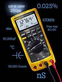
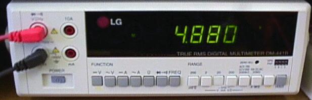
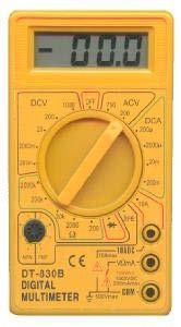
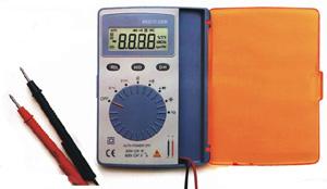
12 What is a digital meter?
13 DVOM - Digital Volt-Ohm Meter A digital volt-ohm meter (DVOM) should be the standard hand held tester for testing electrical voltage, amperes, and resistance in all automotive shops. A DVOM is different from older testers in that the input impedance is high and it will not drain off any significant current to activate the meter. Many computer control circuits are very sensitive to any load created by testing equipment and will give improper readings if measured with an older low impedance analog (sweep hand) meter.
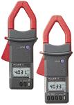
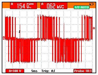
14 Why True-RMS? Electrical professionals today need current clamps that are up to the challenge of accurately measuring harmonic currents caused by non-linear loads. Virtually all electronic equipment falls into this category PCs, printers, HID lighting, adjustable speed drives, etc. Average-sensing meters can't do the job. They can produce readings that are 30%-50% low. Why? Harmonics cause distorted waveforms, and averagesensing meters can only accurately measure pure sine waves. One measure of waveform distortion is Crest Factor, the ratio of the peak to the rms value of the wave. CF for a pure sine wave is 1.4. Higher CF indicates harmonic currents.

15
16 GENERAL TERMS AND THEORY In order for electricity to work, it needs a complete circuit. It has to be able to not only leave the battery, it has to have a path back to it! Normally, the last part of that path is through the metal of the body and this is called "ground". All references to a voltage are in relationship to this ground. Volts; This is the force behind the electricity. Or the "pressure" at the faucet. Amps; This is how much electricity flows. Or gallons per minute of water through the hose. Ohms; This is the resistance of the wire to flow of electricity. Or thinking of the difference between a small diameter hose and a large diameter hose. The range of ohms goes from zero to infinity. Zero ohms is when it's real easy for the electricity to flow. A reading of infinity is when there is no path for the electricity to go through (a closed valve).
17 GENERAL TERMS AND THEORY Cont. Watts; This is power and is a function of amps and volts. DC; Direct current. Other than within the alternator, all of the voltages in your car is "direct" current. AC; Alternating current. This is what you would see in the wiring in your house. 110 volts is in reality a wave that goes from a positive value to a negative value. Don't play with the house wiring!! Primary voltage; This is the input voltage to the coil and is around 12 volts (I'm trying to keep it simple!). Secondary voltage; This is the output from the coil and is MAJOR voltage. This is what ends up going to the spark plugs and will cause personal damage if you grab it!

18 XYZ s of Oscilloscopes

19 Basic Wave Forms
20 Types of Waves Sine Waves Square and rectangular waves Triangle and saw-tooth waves Step and pulse shapes Periodic and non-periodic signals Synchronous and asynchronous signals Complex waves
21
22
23
24
25
26
27
28
29
30
31
32
33
34
35
36

37 What is Electricity Everything is made of atoms There are 118 elements, an atom is a single part of an element Atom consists of electrons, protons, and neutrons
 Amount of water falling at one point at any moment Measured in amperes Resistance (R) Constriction of water Measured in")
38 Waterfalls and Circuits: More in common than you think Electrical Circuits can be thought of as a waterfall Voltage (V) Height of Waterfall Measured in volts Amperage or Current (I) Amount of water falling at one point at any moment Measured in amperes Resistance (R) Constriction of water Measured in ohms
39 Voltage A battery positive terminal (+) and a negative terminal (-). The difference in charge between each terminal is the potential energy the battery can provide. This is labeled in units of volts. Water Analogy
 Some materials have weak attractions and allow electrons to be lost, these are called conductors (copper, silver, gold, aluminum) Electrons can be made to move from one atom to")
40 Electrons (- charge) are attracted to protons (+ charge), this holds the atom together Some materials have strong attraction and refuse to loss electrons, these are called insulators (air, glass, rubber, most plastics) Some materials have weak attractions and allow electrons to be lost, these are called conductors (copper, silver, gold, aluminum) Electrons can be made to move from one atom to another, this is called a current of electricity.
.")

41 Surplus of electrons is called a negative charge (-). A shortage of electrons is called a positive charge (+). A battery provides a surplus of electrons by chemical reaction. By connecting a conductor from the positive terminal to negative terminal electrons will flow.


42 Voltage is like differential pressure, always measure between two points. Measure voltage between two points or across a component in a circuit. When measuring DC voltage make sure polarity of meter is correct, positive (+) red, negative (-) black.
43 Voltage Sources:
44 Exercise Measure DC voltage from power supply using multimeter Measure DC voltage from power supply using oscilloscope Measure DC voltage from battery using multimeter Measure AC voltage from wall outlet using a multimeter Measure AC voltage from wall outlet using an oscilloscope Effective or Root Mean Square Voltage (Measured with multimeter) E ERMS=0.707xEA
45 Ground

46 Current Uniform flow of electrons thru a circuit is called current. WILL USE CONVENTIONAL FLOW NOTATION ON ALL SCHEMATICS

47 To measure current, must break circuit and install meter in line. Measurement is imperfect because of voltage drop created by meter.
 Device inhibiting the flow of electrons Measured in ohms http://www.timboucher.com/journal/index.php?")
48 Simple Electric Circuit Electrons flow from NEGATIVE to POSITIVE Voltage (V) Battery of the system Measured in volts Amperage (I) Component using Electricity Measured in amperes Resistance (R) Device inhibiting the flow of electrons Measured in ohms
49 DC power supplies Little or no AC on DC AC on DC causes failures DC can run on AC link Often AC neutral is us used for DC DC can be combined with other DC power supplies Use batteries or other DC is non discriminatory except for polarity
50 A/C Power
51 AC AC is discriminatory Phase sensitive Level sensitive Polarity sensitive Sensitive to DC Noise sensitive Carrier of noise Noise carried throughout system
52
53
54
55
56 Inputs and Outputs Binary Input Output Analog Input Output
")
 (AC or DC) Virtual")
57 Inputs Externally Powered Binary Inputs Opto-Inputs (AC or DC) Internally Powered (On board controller) (AC or DC) Virtual Two States


58 Binary Outputs Contact Open/Closed AC or DC Two state
59 LOADS AND SWITCHES Manufacturers design devices with the correct amount of resistance for the device to perform the desired amount of energy conversion. Electrical energy flows through the device and is converted to another form of energy ( light, heat, motion, etc.). A load cannot operate unless the circuit provides a complete path for electrons to flow. Switches are used to control and / or provide safety protection. Switches are wired in series with the load.
60 LOADS AND SWITCHES When more than one load is connected to a power source, switches are connected in series with each load and each load is connected in parallel with the power source.
61 OVERLOAD PROTECTORS Many motors have an overload protection device in addition to any device that may be found in the power circuit. These are usually a bimetal disc that will deflect and open the circuit if an overload occurs.
62 Analog Input 0-10 VDC 4-20 ma DC Resistance Current Voltage Output 0-10 VDC 4-20 ma DC Resistance Current Voltage
63 Analog voltage & current time Voltage Current


64 Analogue Input AC or DC 0 - ~
 Extended sensor range Thermistor = Temperature sensitive")
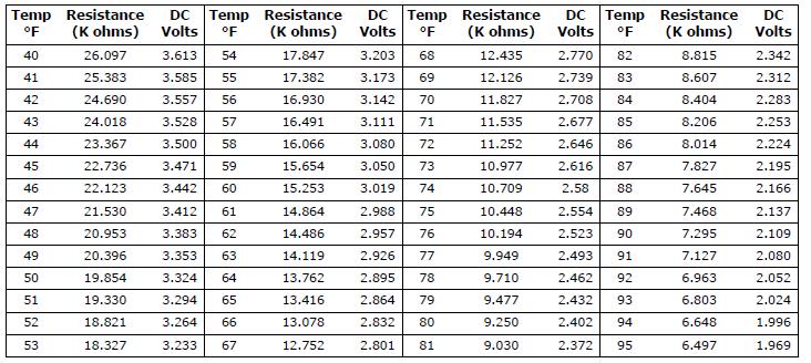
65 RTD =Resistance Temperature detection. Pure metals material (PTC) Extended sensor range Thermistor = Temperature sensitive resistors. Ceramic or polymer material (NTC). Limited range.

66
67

68 Analog Inputs


69 AC or DC 0 - ~ Analogue Output
70

71
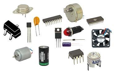
72 Components
73 Summary of schematic symbols + Battery Resistor Potentiometer AC voltage source Capacitor Potentiometer 2-inputs plus center tap Ground Inductor Diode External connection Non-connecting wires - + Op amp
74 Circuit Component classification Resistance Inductor Capacitor
75
76 Electrical & Electronics
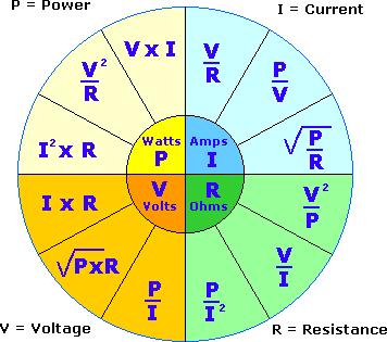
77 Ohm s Law I = E R Where: I = current (amperes, A) E = voltage (volts, V) R = resistance (ohms, Ω) If two of the values are known, you can solve the equation to find the other.
78 Simple Electric Circuit Electrons flow from NEGATIVE to POSITIVE Voltage (V) Battery of the system Measured in volts Amperage (I) Component using Electricity Measured in amperes Resistance (R) Device inhibiting the flow of electrons Measured in ohms
79 Ohm s Law Pie Chart Using the pie chart, cover the value that you want to find. By covering the I, you see that the formula is E divided by R. By covering the R, you see that the formula is E divided by I. By covering the E, you find that the formula is I times R. NEXT
80 OHM S LAW
81 TYPES OF RESISTANCE Pure Resistance Inductive Reactance Capacitive Reactance Pure resistance remains constant, such as in a heating element or a light bulb. Inductive reactance is caused by the magnetic field that develops around a conductor, especially in coils or motors. Capacitors store and discharge electrons that create an opposition to current flow. The total of pure resistance, inductive reactance, and capacitive reactance is called Impedance. NEXT
82 RESISTANCE Electron flow is energy in motion and must be controlled. Resistance refers to anything offering opposition to current flow. There are several types of resistance that will be discussed, but a basic understanding of Ohm s Law is is necessary before that discussion. NEXT
83 MEASURING RESISTANCE An ohmmeter is used to measure pure resistance. Batteries inside the meter provide a power supply to measure electron movement. NEVER connect an ohmmeter to a circuit with the power on or damage to the meter may occur. Also, be sure that the component you are measuring is electrically disconnected to prevent a feedback circuit and false readings. Resistance can be calculated on live circuits by measuring voltage and amperage, then using Ohm s Law, voltage divided by amperage equals resistance. NEXT
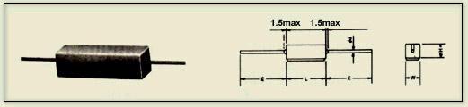
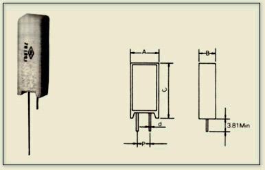
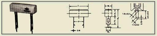
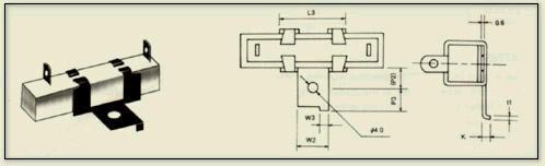
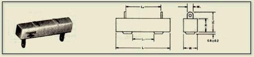
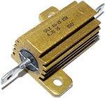
84 Resistance All materials have a resistance that is dependent on cross-sectional area, material type and temperature. A resistor dissipates power in the form of heat

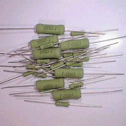
85 Various resistors types

86 When measuring resistance, remove component from the circuit.

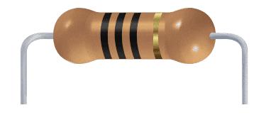
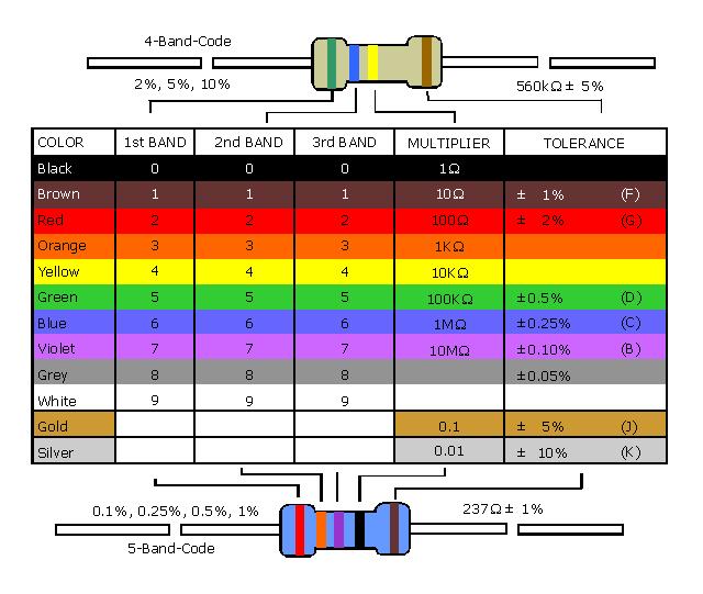
87 Resistor Color Code
88
89 Ohm s Law
90
91
92
93
94 RESISTANCE VS IMPEDANCE Until this time, we only discussed resistance. I said that resistance is the opposition to the flow of current. While this is true, it would be more precise to say that resistance is the opposition to the flow of direct current. Impedance is the opposition to the flow of alternating current. AC causes some devices to act differently than they do with DC. This is true with speakers. If you use a voltmeter to measure the resistance of a speaker's voice coil, you may read something like 3.2 ohms (resistance) even if the speaker is rated at 4 ohms (impedance). To measure the impedance of a speaker you need an instrument called an impedance bridge. The impedance of a speaker is not a constant. It's actual impedance changes with frequency and can vary greatly. Manufacturers give you a nominal impedance, which is generally the average impedance that the speaker will present to the amplifier when driven within the audio spectrum.
95 Resistors Can be rated by Resistance (Ohms, ) Tolerance (% of nominal value) Power Rating (Watts) Schematic Symbol
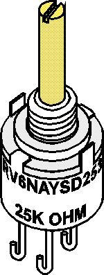
96 Components Resistor Types
97 Series Circuits One current path, therefore the current is the same everywhere Total resistance is the sum of the individual resistances RT = R R
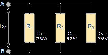
98 Parallel Circuits More than one current path Total current is the sum of the individual currents IT = I I
99 SERIES CIRCUITS A series circuit has one single path for current flow. If the connection is broken or if one of the components fail, current flow stops in the entire circuit.
100 TOTAL RESISTANCE IN A SERIES CIRCUIT A series circuit has only one path for current flow. Therefore, the total resistance is the sum of all of the resistances in the circuit. R total = R 1 + R 2 + R 3.
101 PARALLEL CIRCUITS A parallel circuit has more than one path for current flow. Current flows through each load independent of the others. The current flow through each load is not necessarily equal, but the voltage supplied across the load is always equal.
102 TOTAL RESISTANCE IN A PARALLEL CIRCUIT Since a parallel circuit has more than one path for current flow, adding additional paths (loads) will decrease the total resistance in the circuit. The formula to calculate the total resistance in a parallel circuit is: Check your math! The total resistance in a parallel circuit will always be less than the smallest resistance in the circuit!
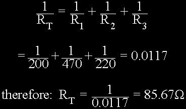
103 TOTAL RESISTANCE IN A PARALLEL CIRCUIT
 / (R1")
104 TOTAL RESISTANCE IN A PARALLEL CIRCUIT R Total = (R1 X R2) / (R1 +R2)

105


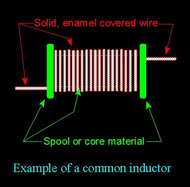
106 Inductors (Chokes) Inductors are simple coils of wire Stores energy in the form of magnetic fields Unit of measure is Henries Used to delay and reshape alternating currents

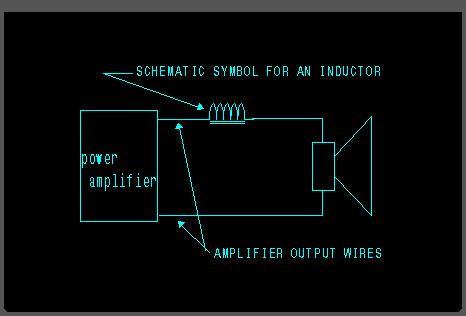
107 Inductor in use
108
109
110
111 INDUCTOR An inductor is an electronic device which consists of a coil of wire which may have a metallic or ferrite core. If it appears to have no core, it is considered to have an air core. The core material will greatly affect the value of the inductor. The unit of measure is the 'henry', but since that is such a large value of inductance, the value is usually stated in millihenries. One henry is equal to one thousand millihenries. If everything else stays constant, increasing the number of turns of wire around the core, will increase the value of the inductor.
112
113
114
115
, and a secondary (outgoing voltage).")

116 SINGLE PHASE TRANSFORMERS Transformers have two windings, a primary (incoming voltage), and a secondary (outgoing voltage). Voltage at the secondary (step-up or step-down) is determined by the number of coils in the secondary versus the number of coils in the primary. Single phase transformers are rated by VA (volts x amps) at the secondary.

117 THREE PHASE TRANSFORMERS Three phase transformers are wound in wye or delta configurations. Combinations of wye and / or delta primary and secondary coils provide a variety of voltage and current outputs.
118 HIGH LEG SYSTEM In a high leg system, voltage from two of the hot legs to neutral will read 115 volts. However, one of the hot legs to neutral will register 208 volts. This is sometimes called the high leg, stinger leg, or crazy leg, and cannot be used for 115 volt circuits.

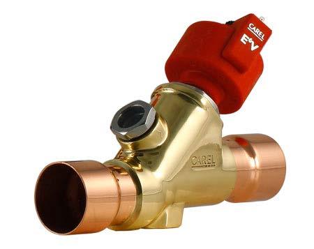
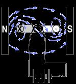
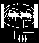
119 SOLENOID VALVE When current flows through the coil of a solenoid valve, the electromagnetism lifts the plunger, opening the valve. (Some valves are designed to close when energized.)
120 RELAYS A relay uses electromagnetism to operate a switch (or contacts). The electrical circuit to the relay coil is entirely separate from the circuit through the contacts. A relay allows high current loads to be controlled using low current control switches and safeties.
 are replaceable, whereas a relay is generally replaced as a complete unit.")
121 A contactor is basically a large rely. The contacts are much larger and capable of carrying more current. Contactor components (contacts, coil, etc.) are replaceable, whereas a relay is generally replaced as a complete unit. CONTACTORS Any number of switches may be located in the contactor coil control circuit.
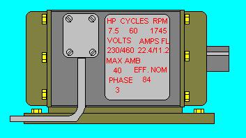
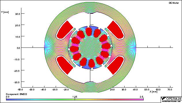
122 MOTORS
 and the stator (stationary electromagnetic coils arranged in a")

123 INDUCTION MOTORS There are two main parts of a motor, the rotor (the part that rotates) and the stator (stationary electromagnetic coils arranged in a circular pattern). The rotor is placed inside the the stator. End bells with bearings are used on each end of the motor and the assembly is bolted together.

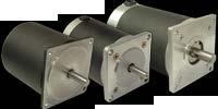

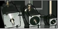

124 Stepper motor
125 Stepper motor Rotor has permanent magnet Constant power motors As speed increases motor torque decreases Motors vibrate more than standard motor The more phase the motor has the less vibration is experienced Bipolar motors have a single winding per phase Unipolar motors have two windings per phase

126 AMPERAGE Ampere, amperage, amps, and current are terms commonly used to describe the quantity and intensity of electrons moving through a conductor. When current flows through a conductor, a magnetic field is created. The clamp-on ammeter is most commonly used on AC circuits. NEXT
127 WATTAGE Electrical power is the rate at which electricity is used to perform useful work.the work performed is measured in units called watts. Watts are calculated by multiplying amperage x voltage. W = I x E 746 Watts is equal to 1 horsepower. NEXT
128 Power Power is an indication of how much work (the conversion of energy from one form to another) can be done in a specific amount of time; that is, a rate of doing work P = W t 1 Watt (W) = 1 joule / second
129

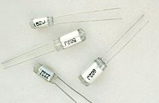
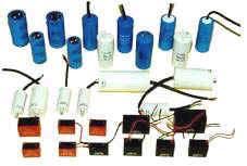
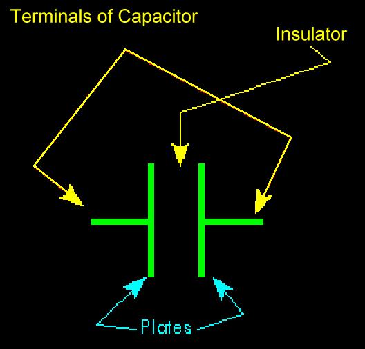
130 Capacitance A capacitor is used to store charge for a short amount of time 90 Deg lag in signal Unit of Measure Farad
131
132
133 CAPACITOR A capacitor is an electronic device which consists of two plates separated by some type of insulator. A capacitor's value is commonly referred to in microfarads, one millionth of a farad. It is expressed in micro farads because the farad is such a large value of capacitance. When a DC voltage source is applied to the capacitor there is an initial surge of current, then the current stops. When the current stops flowing, the capacitor is in a charged state. If the DC source is removed from the capacitor, the capacitor will retain a voltage across its terminals. This charge can be discharged by connecting the plates together. Generally, if an AC voltage source is connected across the capacitor, the current will flow through the capacitor until the source is removed. The exceptions to the situation, where an AC voltage is applied to a capacitor, are going to be explained later.
134 Capacitance A capacitor is used to store charge for a short amount of time Capacitor Battery Unit = Farad Pico Farad - pf = F Micro Farad - uf = 10-6 F
135
136 Capacitor Charging
137 Capacitor Discharge
138 Capacitors How much is it??? Parallel Circuit Ct=C1+C2 Series Circuits For 2 Capacitors Ct=(C1xC2)/(C1+C2) For more than 2 capacitors in series Ct=(1)/((1/C1)+(1/C2)+(1/C3))etc.

139
140
141
142
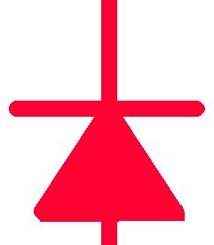
143 DIODES In general a diode will pass current in only one direction. There are a few exceptions like zener and current regulator diodes. When the voltage on the anode is more positive than the voltage on the cathode, current will flow through the diode. If the voltage is reversed, making the cathode more positive, then current will not flow through the diode.
144
145
146 DIODES In general a diode will pass current in only one direction. There are a few exceptions like zener and current regulator diodes. When the voltage on the anode is more positive than the voltage on the cathode, current will flow through the diode. If the voltage is reversed, making the cathode more positive, then current will not flow through the diode.
147
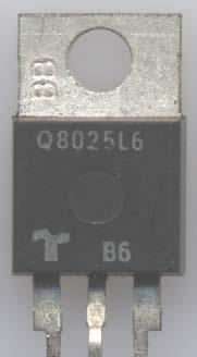
148 TRIAC
149
150
151 The bipolar junction transistor consists of three layers of highly purified silicon (or germanium) to which small amounts of boron (p-type) or phosphorus (n-type) have been added. The boundary between each layer forms a junction, which only allows current to flow from p to n. Connections to each layer are made by evaporating aluminum on the surface; the silicon dioxide coating protects the nonmetalized areas. A small current through the base-emitter junction causes a current 10 to 1000 times larger to flow between the collector and emitter. (The arrows show a positive current; the names of layers should not be taken literally.) The many uses of the junction transistor, from sensitive electronic detectors to powerful hifi amplifiers, all depend on this current amplification. Microsoft Corporation. All Rights Reserved. "Bipolar Junction Transistors," Microsoft Encarta Encyclopedia Microsoft Corporation. All rights reserved.
152
153
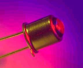
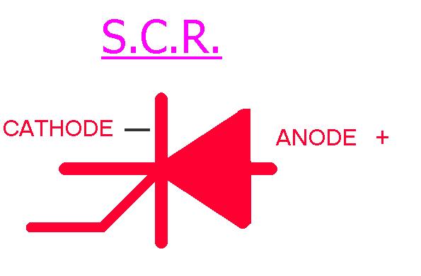
154 The S.C.R.
155
156 Wow the SCR works A pulse of control current applied to the gate will switch the SCR into conduction. Dropping cathode to anode current below the holding current turns the SCR off. The SCR is a switch. The SCR only conducts in one direction.
157 Triac
158 TRIACS Triacs are like SCRs but they conduct in Both directions and switch either polarity of an applied voltage.
159

160
161
162 Binary: How does K1 get energized?
163 The Transistor

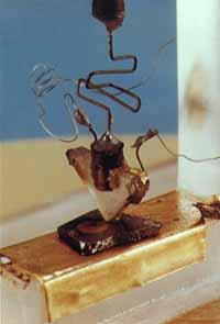
164 Shockley s sandwitch transistor


165 BJT Transistors: NPN Transistor Sandwiching a P-type layer between two n- type layers. PNP Transistor Sandwiching a N-type layer between two p- type layers.

166 How a NPN Transistor works? The base-emitter diode (forward) acts as a switch. when v1>0.7 it lets the electrons flow toward collector. so we can control our output current (Ic) with the input current (Ib) by using transistors. C B E backward Forward
167 Transistors have three terminals: Base Collector Emitter Active: Always on Ic=BIb Transistors work in 3 regions Saturation :Ic=Isaturation On as a switch Off :Ic=0 Off as a switch

168 Transistor as a Switch Transistors can be used as switches. 1 Transistor Switch Transistors can either conduct or not conduct current. 2 ie, transistors can either be on or off. 2
169 Transistor Switching Example 15 X 12V Variable Voltage Supply When V BE is less than 0.7V the transistor is off and the lamp does not light. When V BE is greater than 0.7V the transistor is on and the lamp lights.
170 Transistor
171 PNP Transistor Negative Negative Positive
172 NPN Transistor Positive Positive Negative
173 Transistor operation Gate or Base is the switch input to turn on the transistor The Emitter and collector act as the path for current to flow. Can be used as switch, regulator or amplifier

174
175 What does Onto-input do?
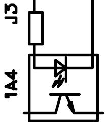
176 OPTO
177
178
179
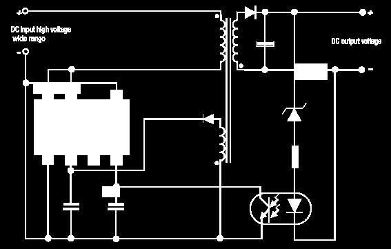
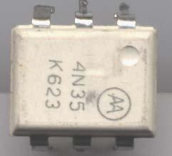
180 WHAT IS THE OPTO? The phototransistor uses a transparent dielectric channel to isolate and insulate a LED from the phototransistor. The LED portion of the opto sensor connects to the input supply it puts out the signal to the phototransistor which sends the input signal to perform the proper action.
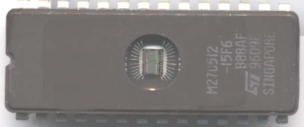
181 EPROM


182 EPROM [erasable programmable read-only memory] First appeared 1977 : a programmable read-only memory that can be erased by exposure to ultraviolet radiation
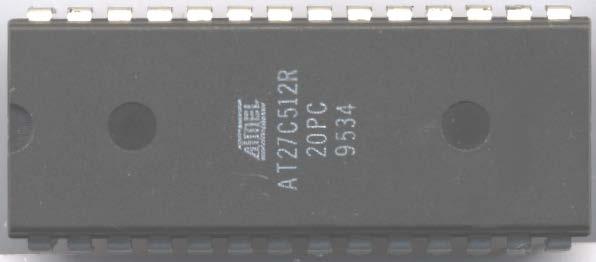
183 EEPROM


184 EEPROM Electrically erasable programmable ROM With normal ROMs you have to replace the chip (or chips) when new BIOS instructions are introduced. With EEPROMs, a program tells the chip's controller to give it electronic amnesia and then downloads the new BIOS code into it. This means a manufacturer can easily distribute BIOS updates on floppy, for instance. This feature is also called flash BIOS, and you might also come across it in devices like modems and graphics/video cards.
185
186
187
188 Circuits
189 Or
190 And
191 Not
192 NAND
193 NOR
194 Combination
195 Permissions
SECTION 3 BASIC AUTOMATIC CONTROLS UNIT 12 BASIC ELECTRICITY AND MAGNETISM. Unit Objectives. Unit Objectives 2/29/2012
 SECTION 3 BASIC AUTOMATIC CONTROLS UNIT 12 BASIC ELECTRICITY AND MAGNETISM Unit Objectives Describe the structure of an atom. Identify atoms with a positive charge and atoms with a negative charge. Explain
FCC Technician License Course
 FCC Technician License Course 2014-2018 FCC Element 2 Technician Class Question Pool Presented by: Tamiami Amateur Radio Club (TARC) WELCOME To the SECOND of 4, 3-hour classes presented by TARC to prepare
Contents. Acknowledgments. About the Author
 Contents Figures Tables Preface xi vii xiii Acknowledgments About the Author xv xvii Chapter 1. Basic Mathematics 1 Addition 1 Subtraction 2 Multiplication 2 Division 3 Exponents 3 Equations 5 Subscripts
FCC Technician License Course
 FCC Technician License Course 2018-2022 FCC Element 2 Technician Class Question Pool Presented by: Tamiami Amateur Radio Club (TARC) WELCOME To the SECOND of 3, 4-hour classes presented by TARC to prepare
Unit 3 Magnetism...21 Introduction The Natural Magnet Magnetic Polarities Magnetic Compass...21
 Chapter 1 Electrical Fundamentals Unit 1 Matter...3 Introduction...3 1.1 Matter...3 1.2 Atomic Theory...3 1.3 Law of Electrical Charges...4 1.4 Law of Atomic Charges...4 Negative Atomic Charge...4 Positive
Preface...x Chapter 1 Electrical Fundamentals
 Preface...x Chapter 1 Electrical Fundamentals Unit 1 Matter...3 Introduction...3 1.1 Matter...3 1.2 Atomic Theory...3 1.3 Law of Electrical Charges...4 1.4 Law of Atomic Charges...5 Negative Atomic Charge...5
Chapter 3. Electricity, Components and Circuits. Metric Units
 Chapter 3 Electricity, Components and Circuits Metric Units 1 T5B02 -- What is another way to specify a radio signal frequency of 1,500,000 hertz? A. 1500 khz B. 1500 MHz C. 15 GHz D. 150 khz T5B07 --
Revised April Unit/Standard Number. Proficiency Level Achieved: (X) Indicates Competency Achieved to Industry Proficiency Level
 Indicates Competency Achieved to Industry Proficiency Level") Unit/Standard Number Electrical, Electronic and Communications Engineering Technology/Technician CIP 15.0303 Task Grid Secondary Competency Task List 100 SAFETY 101 Demonstrate an understanding of state,
Unit/Standard Number Electrical, Electronic and Communications Engineering Technology/Technician CIP 15.0303 Task Grid Secondary Competency Task List 100 SAFETY 101 Demonstrate an understanding of state,
Entry Level Assessment Blueprint Electronics Technology
 Blueprint Test Code: 4135 / Version: 01 Specific Competencies and Skills Tested in this Assessment: Safety Practices Demonstrate safe working procedures Explain the purpose of OSHA and how it promotes
Electrical, Electronic and Communications Engineering Technology/Technician CIP Task Grid
 Secondary Task List 100 SAFETY 101 Describe OSHA safety regulations. 102 Identify, select, and demonstrate proper hand tool use for electronics work. 103 Recognize the types and usages of fire extinguishers.
Revised April Unit/Standard Number. High School Graduation Years 2016, 2017 and 2018
 Unit/Standard Number High School Graduation Years 2016, 2017 and 2018 Electrical, Electronic and Communications Engineering Technology/Technician CIP 15.0303 Task Grid Secondary Competency Task List 100
GCSE Electronics. Scheme of Work
 GCSE Electronics Scheme of Work Week Topic Detail Notes 1 Practical skills assemble a circuit using a diagram recognize a component from its physical appearance (This is a confidence building/motivating
Electrical Fundamentals and Basic Components Chapters T2, T3, G4
 Electrical Fundamentals and Basic Components Chapters T2, T3, G4 Some Basic Math, Electrical Fundamentals, AC Power, The Basics of Basic Components, A Little More Component Detail, Reactance and Impedance
REQUIRED SKILLS AND KNOWLEDGE UEENEEE104A. Topic and Description NIDA Lesson CARD #
 REQUIRED SKILLS AND KNOWLEDGE UEENEEE104A KS01-EE104A Direct current circuits T1 Topic and Description NIDA Lesson CARD # Basic electrical concepts encompassing: electrotechnology industry static and current
Basic Electronics. Chapter 2, 3A (test T5, T6) Basic Electrical Principles and the Functions of Components. PHYS 401 Physics of Ham Radio
 Basic Electrical Principles and the Functions of Components. PHYS 401 Physics of Ham Radio") Basic Electronics Chapter 2, 3A (test T5, T6) Basic Electrical Principles and the Functions of Components Figures in this course book are reproduced with the permission of the American Radio Relay League.
Basic Electronics Chapter 2, 3A (test T5, T6) Basic Electrical Principles and the Functions of Components Figures in this course book are reproduced with the permission of the American Radio Relay League.
Unit/Standard Number. LEA Task # Alignment
 1 Secondary Competency Task List 100 SAFETY 101 Demonstrate an understanding of State and School safety regulations. 102 Practice safety techniques for electronics work. 103 Demonstrate an understanding
General Licensing Class Circuits
 General Licensing Class Circuits Valid July 1, 2011 Through June 30, 2015 1 Amateur Radio General Class Element 3 Course Presentation ELEMENT 3 SUB-ELEMENTS (Groupings) Your Passing CSCE Your New General
Calhoon MEBA Engineering School. Study Guide for Proficiency Testing Industrial Electronics
 Calhoon MEBA Engineering School Study Guide for Proficiency Testing Industrial Electronics January 0. Which factors affect the end-to-end resistance of a metallic conductor?. A waveform shows three complete
Radio Merit Badge Boy Scouts of America
 Radio Merit Badge Boy Scouts of America Module 2 Electronics, Safety & Careers BSA National Radio Scouting Committee2012 Class Format Three modules any order Module 1 Intro To Radio Module 2 Electronic
Electromechanical Technology /Electromechanical Engineering Technology CIP Task Grid
 1 Secondary Task List 100 DEMONSTRATE KNOWLEDGE OF TECHNICAL REPORTS 101 Identify components of technical reports. 102 Demonstrate knowledge of the common components of technical documents. 103 Maintain
Basic Electrical Training
 Basic Electrical Training Electricians Tools Explain how various hand tools are used by an electrician Discuss the safe use of hand tools and power tools Perform basic calculations and measurement conversions
Perkins Statewide Articulation Agreement. Documentation item: Secondary Competency Task List Coversheet
 Perkins Statewide Articulation Agreement Documentation item: Secondary Task List Coversheet The Secondary School agrees to: A. Implement the approved PDE Program(s) of Study. B. Provide assessment of student
SUBELEMENT T5 Electrical principles: math for electronics; electronic principles; Ohm s Law 4 Exam Questions - 4 Groups
 SUBELEMENT T5 Electrical principles: math for electronics; electronic principles; Ohm s Law 4 Exam Questions - 4 Groups 1 T5A Electrical principles, units, and terms: current and voltage; conductors and
Industrial Electrician Level 3
 Industrial Electrician Level 3 Industrial Electrician Unit: C1 Industrial Electrical Code I Level: Three Duration: 77 hours Theory: Practical: 77 hours 0 hours Overview: This unit is designed to provide
+ 24V 3.3K - 1.5M. figure 01
 ELECTRICITY ASSESSMENT 35 questions Revised: 08 Jul 2013 1. Which of the wire sizes listed below results in the least voltage drop in a circuit carrying 10 amps: a. 16 AWG b. 14 AWG c. 18 AWG d. 250 kcmil
Curriculum. Technology Education ELECTRONICS
 Curriculum Technology Education ELECTRONICS Supports Academic Learning Expectation # 3 Students and graduates of Ledyard High School will employ problem-solving skills effectively Approved by Instructional
Technician License Course Chapter 3. Lesson Plan Module 4 Electricity
 Technician License Course Chapter 3 Lesson Plan Module 4 Electricity Fundamentals of Electricity Radios are powered by electricity and radio signals are a form of electrical energy. A basic understanding
Table of Contents. Introduction...2 Conductors and Insulators...3 Current, Voltage, and Resistance...6
 Table of Contents Introduction...2 Conductors and Insulators...3 Current, Voltage, and Resistance...6 Ohm s Law... 11 DC Circuits... 13 Magnetism...20 Alternating Current...23 Inductance and Capacitance...30
Exercise 9. Electromagnetism and Inductors EXERCISE OBJECTIVE DISCUSSION OUTLINE DISCUSSION. Magnetism, magnets, and magnetic field
 Exercise 9 Electromagnetism and Inductors EXERCISE OBJECTIVE When you have completed this exercise, you will be familiar with the concepts of magnetism, magnets, and magnetic field, as well as electromagnetism
Power. Power is the rate of using energy in joules per second 1 joule per second Is 1 Watt
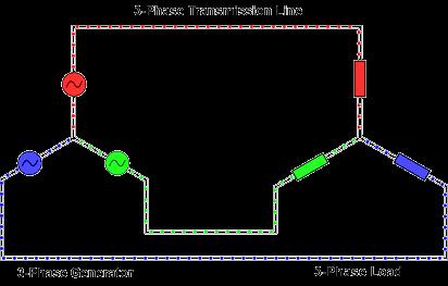
 3 phase Power All we need electricity for is as a source of transport for energy. We can connect to a battery, which is a source of stored energy. Or we can plug into and electric socket at home or in
Definitions of Technical Terms
 Definitions of Technical Terms Terms Ammeter Amperes, Amps Band Capacitor Carrier Squelch Diode Dipole Definitions How is an ammeter usually connected = In series with the circuit What instrument is used
Electronic Components (Elements)
") Lecture_3 Electronic Components (Elements) Instructor: IBRAHIM ABU-ISBEIH 25 July 2011 Reverse Engineering 1 Objectives: After completing this class, you will be able to identify the most commonly used
Lecture_3 Electronic Components (Elements) Instructor: IBRAHIM ABU-ISBEIH 25 July 2011 Reverse Engineering 1 Objectives: After completing this class, you will be able to identify the most commonly used
POS Perkins Statewide Articulation Agreement Documentation Coversheet
 POS Perkins Statewide Articulation Agreement Documentation Coversheet Student Name: Secondary School Name: Secondary School Address: CTE Program of Study: CIP # CIP Program Name Grade 9 1. CAREER AND TECHNICAL
Entry Level Assessment Blueprint Electronics
 Entry Level Assessment Blueprint Electronics Test Code: 3034 / Version: 01 Specific Competencies and Skills Tested in this Assessment: Safety Demonstrate understanding of SDS Exhibit understanding of ESD
Workshop Part Identification Lecture N I A G A R A C O L L E G E T E C H N O L O G Y D E P T.
 Workshop Part Identification Lecture N I A G A R A C O L L E G E T E C H N O L O G Y D E P T. Identifying Resistors Resistors can be either fixed or variable. The variable kind are called potentiometers
ELECTRONICS AND ELECTRICITY
 INTRODUCTION ELECTRONICS ND ELECTRICITY The science of Electronics and Electricity makes a very important contribution to our everyday existence. Electricity is concerned with the generation, transmission
Technician Licensing Class T6
 Technician Licensing Class T6 Amateur Radio Course Monroe EMS Building Monroe, Utah January 11/18, 2014 January 22, 2014 Testing Session Valid dates: July 1, 2010 June 30, 2014 Amateur Radio Technician
Generator Advanced Concepts
 Generator Advanced Concepts Common Topics, The Practical Side Machine Output Voltage Equation Pitch Harmonics Circulating Currents when Paralleling Reactances and Time Constants Three Generator Curves
Electrical Theory. Power Principles and Phase Angle. PJM State & Member Training Dept. PJM /22/2018
 Electrical Theory Power Principles and Phase Angle PJM State & Member Training Dept. PJM 2018 Objectives At the end of this presentation the learner will be able to: Identify the characteristics of Sine
Basic Electronics Prof. T.S. Natarajan Department of Physics Indian Institute of Technology, Madras
 Basic Electronics Prof. T.S. Natarajan Department of Physics Indian Institute of Technology, Madras Lecture 39 Silicon Controlled Rectifier (SCR) (Construction, characteristics (Dc & Ac), Applications,
Long Loopstick Antenna
 Long Loopstick Antenna Wound on a 3 foot length of PVC pipe, the long loopstick antenna was an experiment to try to improve AM radio reception without using a long wire or ground. It works fairly well
Power Electrician Level 3
 s Power Electrician Level 3 Rev. September 2008 Power Electrician Unit: C1 Electrical Code III Level: Three Duration: 60 hours Theory: Practical: 60 hours 0 hours Overview: This unit of instruction is
Experiment (1) Principles of Switching
 Principles of Switching") Experiment (1) Principles of Switching Introduction When you use microcontrollers, sometimes you need to control devices that requires more electrical current than a microcontroller can supply; for this,
Experiment (1) Principles of Switching Introduction When you use microcontrollers, sometimes you need to control devices that requires more electrical current than a microcontroller can supply; for this,
T6+ Analog I/O Section. Installation booklet for part numbers: 5/4-80A-115 5/4-90A-115 5/4-80A /4-90A-1224
 T and T+ are trade names of Trol Systems Inc. TSI reserves the right to make changes to the information contained in this manual without notice. publication /4A115MAN- rev:1 2001 TSI All rights reserved
ELECTRIC CIRCUITS AND ELECTRONICS
 Circuitos eléctricos y electrónicos ELECTRIC CIRCUITS AND ELECTRONICS Technology, programming and robotics II Electric Circuitos circuits eléctricos and y electronics electrónicos AN ELECTRICAL CIRCUIT
Lesson 3: Electronics & Circuits
 Lesson 3: Electronics & Circuits Preparation for Amateur Radio Technician Class Exam Topics Review Ohm s Law Energy & Power Circuits Inductors & Inductance Capacitors & Capacitance Analog vs Digital Exam
Design and Technology
 E.M.F, Voltage and P.D E.M F This stands for Electromotive Force (e.m.f) A battery provides Electromotive Force An e.m.f can make an electric current flow around a circuit E.m.f is measured in volts (v).
Basic Electronics: Diodes and Transistors. October 14, 2005 ME 435
 Basic Electronics: Diodes and Transistors Eşref Eşkinat E October 14, 2005 ME 435 Electric lectricity ity to Electronic lectronics Electric circuits are connections of conductive wires and other devices
Course Objectives Upon completion of this course, technicians should understand and be able to apply their knowledge of:
 Advanced Electronics Study Guide 2004 2006 Melior, Inc. Course Objectives Upon completion of this course, technicians should understand and be able to apply their knowledge of: Concepts, applications and
Capacitors, diodes, transistors
 Capacitors, diodes, transistors capacitors charging and time response filters (impedance) semi-conductor diodes rectifiers transformers transistors CHM6158C - Lecture 3 1 Capacitors Symbol 2 Capacitors
Construction Electrician Level 2
 Level 2 Rev. September 2008 Unit: B1 Electrical Code II Level: Two Duration: 120 hours Theory: Practical: 99 hours 21 hours Overview: This unit of instruction is designed to provide the Electrician apprentice
Auto Diagnosis Test #2 Review
 Auto Diagnosis Test #2 Review Your own hand written notes may be used for the 1 st 10 minutes of the test For the Most Effective Personal Review, Look Over the On Line Study Guide Multimedia Based on Chapters
Chapter 11. Alternating Current
 Unit-2 ECE131 BEEE Chapter 11 Alternating Current Objectives After completing this chapter, you will be able to: Describe how an AC voltage is produced with an AC generator (alternator) Define alternation,
Basic Electronics. Chapter 2 Basic Electrical Principles and the Functions of Components. PHYS 401 Physics of Ham Radio
 Basic Electronics Chapter 2 Basic Electrical Principles and the Functions of Components Figures in this course book are reproduced with the permission of the American Radio Relay League. This booklet was
BASIC ELECTRONICS/ ELECTRONICS
 BASIC ELECTRONICS/ ELECTRONICS PREAMBLE The syllabus is intended to equip candidates with broad understanding of the technology of manufacturing, maintenance and repair of domestic and industrial equipment.
Introduction. A closed loop of wire is not an electrical circuit, a circuit requires
 The Law of Charges Opposite charges attract like charges repel Lines of force can never cross each other The values are equal but the effect is opposite Strength of the attraction is exponential to its
1. What is the unit of electromotive force? (a) volt (b) ampere (c) watt (d) ohm. 2. The resonant frequency of a tuned (LRC) circuit is given by
 volt (b) ampere (c) watt (d) ohm. 2. The resonant frequency of a tuned (LRC) circuit is given by") Department of Examinations, Sri Lanka EXAMINATION FOR THE AMATEUR RADIO OPERATORS CERTIFICATE OF PROFICIENCY ISSUED BY THE DIRECTOR GENERAL OF TELECOMMUNICATIONS, SRI LANKA 2004 (NOVICE CLASS) Basic Electricity,
Department of Examinations, Sri Lanka EXAMINATION FOR THE AMATEUR RADIO OPERATORS CERTIFICATE OF PROFICIENCY ISSUED BY THE DIRECTOR GENERAL OF TELECOMMUNICATIONS, SRI LANKA 2004 (NOVICE CLASS) Basic Electricity,
SUBELEMENT T6 Electrical components: semiconductors; circuit diagrams; component functions 4 Exam Questions - 4 Groups
 SUBELEMENT T6 Electrical components: semiconductors; circuit diagrams; component functions 4 Exam Questions - 4 Groups 1 T6A Electrical components: fixed and variable resistors; capacitors and inductors;
The Discussion of this exercise covers the following points:
 Exercise 5 Resistance and Ohm s Law EXERCISE OBJECTIVE When you have completed this exercise, you will be familiar with the notion of resistance, and know how to measure this parameter using an ohmmeter.
Common Sensors. Understand the following sensors: Pull Up sensor Pull Down sensor Potentiometer Thermistor
 Common Sensors Understand the following sensors: Pull Up sensor Pull Down sensor Potentiometer Thermistor Pull Up Switch (sensor) VERY low current 12 volt Pull Up Switch (sensor) VERY low current 12 volt
Basic Electronics Learning by doing Prof. T.S. Natarajan Department of Physics Indian Institute of Technology, Madras
 Basic Electronics Learning by doing Prof. T.S. Natarajan Department of Physics Indian Institute of Technology, Madras Lecture 38 Unit junction Transistor (UJT) (Characteristics, UJT Relaxation oscillator,
INSTITUTE OF AERONAUTICAL ENGINEERING (AUTONOMOUS) Dundigal, Hyderabad
 Dundigal, Hyderabad") INSTITUTE OF AERONAUTICAL ENGINEERING (AUTONOMOUS) Dundigal, Hyderabad - 500 043 CIVIL ENGINEERING ASSIGNMENT Name : Electrical and Electronics Engineering Code : A30203 Class : II B. Tech I Semester Branch
INSTITUTE OF AERONAUTICAL ENGINEERING (AUTONOMOUS) Dundigal, Hyderabad - 500 043 CIVIL ENGINEERING ASSIGNMENT Name : Electrical and Electronics Engineering Code : A30203 Class : II B. Tech I Semester Branch
MOSFET as a Switch. MOSFET Characteristics Curves
 MOSFET as a Switch MOSFET s make very good electronic switches for controlling loads and in CMOS digital circuits as they operate between their cut-off and saturation regions. We saw previously, that the
Perkins Statewide Articulation Agreement. Documentation item: Secondary Competency Task List Coversheet
 Perkins Statewide Articulation Agreement Documentation item: Secondary Task List Coversheet The Secondary School agrees to: A. Implement the approved PDE Program(s) of Study. B. Provide assessment of student
CURRENT ELECTRICITY. 1. The S.I. unit of power is (a) Henry (b) coulomb (c) watt (d) watt-hour Ans: c
 Henry (b) coulomb (c) watt (d) watt-hour Ans: c") CURRENT ELECTRICITY 1. The S.I. unit of power is (a) Henry (b) coulomb (c) watt (d) watt-hour 2. Electric pressure is also called (a) resistance (b) power (c) voltage (d) energy 3. The substances which
CURRENT ELECTRICITY 1. The S.I. unit of power is (a) Henry (b) coulomb (c) watt (d) watt-hour 2. Electric pressure is also called (a) resistance (b) power (c) voltage (d) energy 3. The substances which
Alternating Current Page 1 30
 Alternating Current 26201 11 Page 1 30 Calculate the peak and effective voltage of current values for AC Calculate the phase relationship between two AC waveforms Describe the voltage and current phase
T6A4. Electrical components; fixed and variable resistors, capacitors, and inductors; fuses, switches, batteries
 Amateur Radio Technician Class Element Course Presentation ti ELEMENT SUB-ELEMENTS Technician Licensing Class Supplement T Electrical/Electronic Components Exam Questions, Groups T - FCC Rules, descriptions
Electronic Components
 Engineering Project (1) Lecture_2 Electronic Components (Elements) Instructor: Eng. IBRAHIM ABU-ISBEIH 6 March 2012 Eng. Ibrahim Abu-Isbeih 1 Objectives: After completing this class, you will be able to
UNIVERSITY OF NORTH CAROLINA AT CHARLOTTE Department of Electrical and Computer Engineering
 UNIVERSITY OF NORTH CAROLINA AT CHARLOTTE Department of Electrical and Computer Engineering EXPERIMENT 2 BASIC CIRCUIT ELEMENTS OBJECTIVES The purpose of this experiment is to familiarize the student with
BASIC ELECTRICITY/ APPLIED ELECTRICITY
 BASIC ELECTRICITY/ APPLIED ELECTRICITY PREAMBLE This examination syllabus has been evolved from the Senior Secondary School Electricity curriculum. It is designed to test candidates knowledge and understanding
BASIC ELECTRICITY/ APPLIED ELECTRICITY
 BASIC ELECTRICITY/ APPLIED ELECTRICITY PREAMBLE This examination syllabus has been evolved from the Senior Secondary School Electricity curriculum. It is designed to test candidates knowledge and understanding
Pre-certification Electronics Questions. Answer the following with the MOST CORRECT answer.
 Electronics Questions Answer the following with the MOST CORRECT answer. 1. The cathode end terminal of a semiconductor diode can be identified by: a. the negative sign marked on the case b. a circular
Introduction. Inductors in AC Circuits.
 Module 3 AC Theory What you ll learn in Module 3. Section 3.1 Electromagnetic Induction. Magnetic Fields around Conductors. The Solenoid. Section 3.2 Inductance & Back e.m.f. The Unit of Inductance. Factors
ECET 211 Electric Machines & Controls Lecture 4-2 Motor Control Devices: Lecture 4 Motor Control Devices
 ECET 211 Electric Machines & Controls Lecture 4-2 Motor Control Devices: Part 3. Sensors, Part 4. Actuators Text Book: Electric Motors and Control Systems, by Frank D. Petruzella, published by McGraw Hill,
Experiment 45. Three-Phase Circuits. G 1. a. Using your Power Supply and AC Voltmeter connect the circuit shown OBJECTIVE
 Experiment 45 Three-Phase Circuits OBJECTIVE To study the relationship between voltage and current in three-phase circuits. To learn how to make delta and wye connections. To calculate the power in three-phase
INSTITUTE OF AERONAUTICAL ENGINEERING Dundigal, Hyderabad
 Course Name Course Code Class Branch INSTITUTE OF AERONAUTICAL ENGINEERING Dundigal, Hyderabad -500 043 AERONAUTICAL ENGINEERING TUTORIAL QUESTION BANK : ELECTRICAL AND ELECTRONICS ENGINEERING : A40203
ELEXBO. Electrical - Experimentation Box
 ELEXBO Electrical - Experimentation Box 1 Table of contents 2 Introduction...3 Basics...3 The current......4 The voltage...6 The resistance....9 Measuring resistance...10 Summary of the electrical values...11
Power systems Protection course
 Al-Balqa Applied University Power systems Protection course Department of Electrical Energy Engineering 1 Part 5 Relays 2 3 Relay Is a device which receive a signal from the power system thought CT and
VCE VET ELECTROTECHNOLOGY
 Victorian Certificate of Education 2010 SUPERVISOR TO ATTACH PROCESSING LABEL HERE STUDENT NUMBER Letter Figures Words VCE VET ELECTROTECHNOLOGY Written examination Thursday 4 November 2010 Reading time:
Electronics 1. Voltage/Current Resistors Capacitors Inductors Transistors
 Electronics 1 Voltage/Current Resistors Capacitors Inductors Transistors Voltage and Current Simple circuit a battery pushes some electrons around the circuit how many per second? Water The easiest way
Question 1 Given a battery and a light bulb, show how you would connect these two devices together with wire so as to energize the light bulb:
 Question 1 Given a battery and a light bulb, show how you would connect these two devices together with wire so as to energize the light bulb: + - file 00001 Answer 1 This is the simplest option, but not
Chapter 12 Electric Circuits
 Conceptual Physics/ PEP Name: Date: Chapter 12 Electric Circuits Section Review 12.1 1. List one way electric current is similar to water current and one way it is different. 2. Draw a circuit diagram
Know and understand you and your co-workers competence level before opening a live panel to diagnose
 MARCH 2014 BASIC ELECTRICAL UNDERSTANDING MARCH 2014 SAFETY FIRST Always use extreme caution when working around electricity A electrical shock can kill you! The purpose of this module is to: Develop basic
Module 04.(B1) Electronic Fundamentals
 Electronic Fundamentals") 1.1a. Semiconductors - Diodes. Module 04.(B1) Electronic Fundamentals Question Number. 1. What gives the colour of an LED?. Option A. The active element. Option B. The plastic it is encased in. Option
1.1a. Semiconductors - Diodes. Module 04.(B1) Electronic Fundamentals Question Number. 1. What gives the colour of an LED?. Option A. The active element. Option B. The plastic it is encased in. Option
Construction Electrician/Industrial Electrician/Power Electrician Common Core Level 2
 Common Core Level 2 Unit: B1 Commercial Electrical Code Level: Two Duration: 60 hours Theory: Practical: 60 hours 0 hours Overview: This unit is designed to provide the apprentice with the knowledge about
APPENDIX D DISCUSSION OF ELECTRONIC INSTRUMENTS
 APPENDIX D DISCUSSION OF ELECTRONIC INSTRUMENTS DC POWER SUPPLIES We will discuss these instruments one at a time, starting with the DC power supply. The simplest DC power supplies are batteries which
WASSCE / WAEC BASIC ELECTRONICS / ELECTRONICS SYLLABUS
 WASSCE / WAEC BASIC ELECTRONICS / ELECTRONICS SYLLABUS WWW.LARNEDU.COM Visit www.larnedu.com for WASSCE / WAEC syllabus on different subjects and more great stuff to help you ace the WASSCE in flying colours.
Using Circuits, Signals and Instruments
 Using Circuits, Signals and Instruments To be ignorant of one s ignorance is the malady of the ignorant. A. B. Alcott (1799-1888) Some knowledge of electrical and electronic technology is essential for
2π LC. = (2π) 2 4/30/2012. General Class Element 3 Course Presentation X C. Electrical Principles. ElectriElectrical Principlesinciples F 2 =
 2 4/30/2012. General Class Element 3 Course Presentation X C. Electrical Principles. ElectriElectrical Principlesinciples F 2 =") General Class Element 3 Course Presentation ti ELEMENT 3 SUB ELEMENTS General Licensing Class Subelement G5 3 Exam Questions, 3 Groups G1 Commission s Rules G2 Operating Procedures G3 Radio Wave Propagation
General Class Element 3 Course Presentation ti ELEMENT 3 SUB ELEMENTS General Licensing Class Subelement G5 3 Exam Questions, 3 Groups G1 Commission s Rules G2 Operating Procedures G3 Radio Wave Propagation
INSTITUTE OF AERONAUTICAL ENGINEERING (Autonomous) Dundigal, Hyderabad
 Dundigal, Hyderabad") I INSTITUTE OF AERONAUTICAL ENGINEERING (Autonomous) Dundigal, Hyderabad-500043 CIVIL ENGINEERING TUTORIAL QUESTION BANK Course Name : BASIC ELECTRICAL AND ELECTRONICS ENGINEERING Course Code : AEE018
I INSTITUTE OF AERONAUTICAL ENGINEERING (Autonomous) Dundigal, Hyderabad-500043 CIVIL ENGINEERING TUTORIAL QUESTION BANK Course Name : BASIC ELECTRICAL AND ELECTRONICS ENGINEERING Course Code : AEE018
Electricity Basics
 Western Technical College 31660310 Electricity Basics Course Outcome Summary Course Information Description Career Cluster Instructional Level Total Credits 4.00 Total Hours 144.00 DC/AC electrical theory
BETWEEN SCAN TOOL & SUCCESSFUL DIAGNOSIS FILLING IN THE GAPS
 ETWEEN SCAN TOOL & SUCCESSFUL DIAGNOSIS FILLING IN THE GAPS 38 April 0 Y ERNIE THOMPSON A scan tool is an invaluable aid to vehicle diagnostics, but you may need to rely on other methods as well when vital
AME140 Lab #2 INTRODUCTION TO ELECTRONIC TEST EQUIPMENT AND BASIC ELECTRONICS MEASUREMENTS
 INTRODUCTION TO ELECTRONIC TEST EQUIPMENT AND BASIC ELECTRONICS MEASUREMENTS The purpose of this document is to guide students through a few simple activities to increase familiarity with basic electronics
CHIEF ENGINEER REG III/2 MARINE ELECTROTECHNOLOGY
 CHIEF ENGINEER REG III/2 MARINE ELECTROTECHNOLOGY LIST OF TOPICS 1 Electric Circuit Principles 2 Electronic Circuit Principles 3 Generation 4 Distribution 5 Utilisation The expected learning outcome is
Syllabus OP49 Test electrical conduction in a variety of materials, and classify each material as a conductor or insulator
 Physics: 14. Current Electricity Please remember to photocopy 4 pages onto one sheet by going A3 A4 and using back to back on the photocopier Syllabus OP49 Test electrical conduction in a variety of materials,
Home Map Projects Construction Soldering Study Components 555 Symbols FAQ Links
 Home Map Projects Construction Soldering Study Components 555 Symbols FAQ Links Circuit Symbols Wires Supplies Output devices Switches Resistors Capacitors Diodes Transistors Audio & Radio Meters Sensors
ECET 211 Electrical Machines and Controls
 ECET 211 Electrical Machines and Controls 2016/4/27 Class Review and Wrapping Up Comprehensive Exam, Friday, 1:00-3:00 PM, May 6, 2016 Close books/allow 1-page (8 x 11 and ½) hand-written review note,
NEW HORIZON PRE UNIVERSITY COLLEGE LESSON PLAN FOR THE ACADEMIC YEAR Department of ELECTRONICS
 NEW HORIZON PRE UNIVERSITY COLLEGE LESSON PLAN FOR THE ACADEMIC YEAR 2017 2018 Department of ELECTRONICS I PUC Month: JUNE I 1. INTRODUCTION TO ELECTRONICS Electronics and its scope: Development of vacuum
Single-Phase Transformation Review
 Single-Phase Transformation Review S T U D E N T M A N U A L March 2, 2005 2 STUDENT TRAINING MANUAL Prerequisites: None Objectives: Given the Construction Standards manual and a formula sheet, you will
Matrix Multimedia Limited Tel Fax
 matrix multimedia Electronic Circuits and Components v2.0 Course material with Virtual Laboratories that stimulate, teach & test. This second version of Electronic Circuits and Components is bigger and