Auto Diagnosis Test #2 Review
|
|
|
- Paulina Kelley
- 5 years ago
- Views:
Transcription


1 Auto Diagnosis Test #2 Review Your own hand written notes may be used for the 1 st 10 minutes of the test For the Most Effective Personal Review, Look Over the On Line Study Guide Multimedia Based on Chapters 15 & 16 and Lab Demonstrations


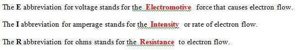
2 Chapter 15 Information #1 Electron Flow! #2 Induction Moving Magnetism through Coils #4 Amperage = Rate of Electron Flow #5 Direct vs. Alternating Current #7 Voltage = Electromotive Force #8 Resistance = Opposition to Electromotive Force Alpha Omega

3 Chapter 15 Information #11 Complete Circuit has Continuity #12 Consumers are the Load in the Circuit Consumer Source Conductive Path
4
5
6
7

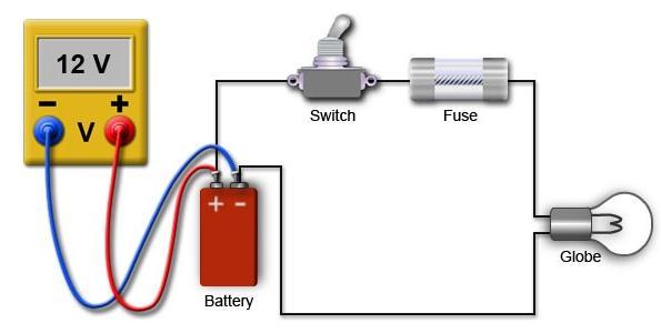
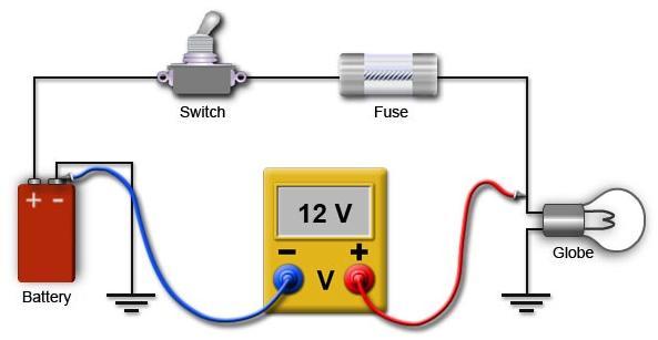
8 Chapter 15 Information #13 Voltage Drop & How to Measure It #14 Electrical Power is Wattage

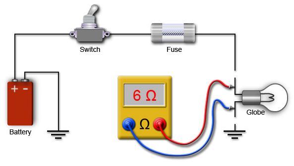
9 Chapter 15 Information #15 Ground Path is Body, Chassis, Engine #16 Ohm s Law

10 Chapter 15 Information #18 Impedance #19 Watt s Law #20 Consumer, Source, Conductive Path

11 Chapter 15 Information #21 Series Circuit Rules & Facts!

12 Chapter 15 Information #21 Series Circuit Rules & Facts!

13 Chapter 15 Information #22 Parallel Circuit Rules & Facts

14 Chapter 15 Information #22 Parallel Circuit Rules & Facts


15 Chapter 15 Information #29 Resistors #31 Stepped or Tapped Resistors Blower Motor #32 Potentiometer TPS or APP #33 Carbon Pile Rheostat

16 Chapter 15 Information #34 Thermistor PTC & NTC #35 Circuit Protection Against Amps Overloads #40 Mercury Switch is Position Sensitive A thermistor is an electronic component that exhibits a large change in resistance with a change in its body temperature. The word thermistor is actually a contraction of the words thermal resistor.

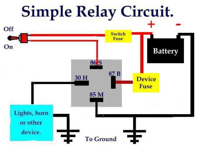
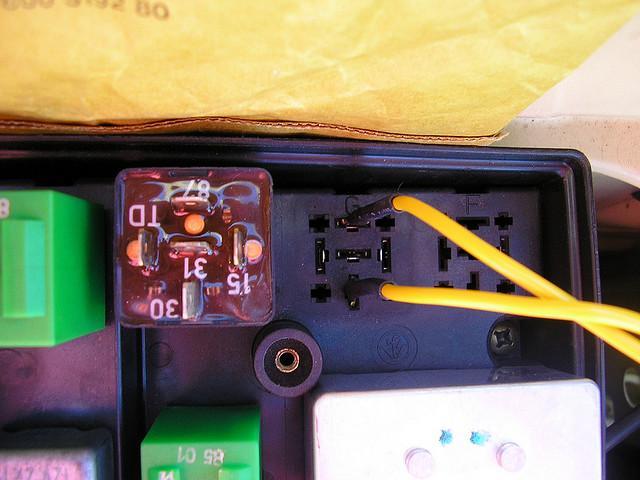
17 Chapter 15 Information #42 Relay Operation & Facts #43 Explain why a Relay is an If:Then switch #44 Same Voltage In as Out

18 Chapter 15 Information 12 Volts in 12 Volts into the Relay Ground Control 12 Volts out of the Relay How can a relay be by passed using a jumper wire?
19 Chapter 15 Information


20 Chapter 15 Information #45 Fused Jumper Wire Use


21 Chapter 15 Information #48 Solenoid Operation & Facts Ground Ground Movable Plunger Movable Plunger Solenoid Coil Solenoid Coil Ground Ground Contacts Open Contacts Closed


22 Chapter 15 Information #49 Conductors #50 Insulators

23 Chapter 15 Information #52 AWG Numbering System (Small # has Big Diameter)

24 Chapter 16 Information #1 Circuit Problems: Opens, Shorts, High Resistances
25 Chapter 16 Information #2 Open = No Continuity & No Flow

26 Chapter 16 Information #2 Short to Ground Blows Fuses

27 Chapter 16 Information #2 Short to Power Turns Circuit On

28 Chapter 16 Information #2 High Resistance Decreases Amps/Current


29 Chapter 16 Information #3 PCM 5 Volt Reference Signal to Sensors #4 Schematic Circuit Drawings #5 Schematic Symbols


 #11 Use")
30 Chapter 16 Information #6 Use of Jumper Wires for Circuit Testing #7 Checking Voltage Available ( + to ) #11 Use of Fused Jumper Wires
 #12 Computer")

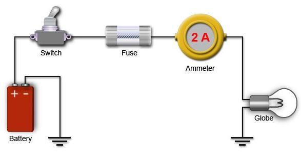
 & ( to ) #18 Measure Amps in Series")
31 Chapter 16 Information #7 Checking Voltage Available ( + to ) #12 Computer Memory Saver #13 DMM 1MΩ to 10MΩ Input Impedance #16 Measure Voltage in Parallel #17 Voltage Drop Testing (+ to +) & ( to ) #18 Measure Amps in Series or Inductively
 #39 The Best Way to Check Wiring is V.D.")
32 Chapter 16 Information #33 Voltage Drop Testing Live Circuit (+ to +) & ( to ) #34 Thermistors (PTC & NTC) #36 Testing a Relay (ohms, jumping, clicking) #39 The Best Way to Check Wiring is V.D. #45 Connectors & Grounds are Numbered

33 Chapter 16 Information #47 Tracing Circuits with a Highlighter #48 The 3 Big Circuit Problems!! #49 Shorted Coil has Less Ohms than Specs Ω in within spec = OK Ω in less than spec = Short Ω either OL or = Open Ω in more than spec = High Resistance

34 Chapter 16 Information #51 Corrosion causes High Resistance #51 Corrosion Reduces Intensity/Current Flow #55 Soldering with Rosin Core Solder #57 After Soldering, Use Heat Shrink Tubing
35 Bring a Calculator Use Ohm s Law in a Series Circuit Use Watt s Law in a Series Circuit
36 Bring a Calculator Put in your own R x values & practice the series circuit math
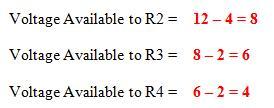
37 Series Circuit with a 12 Volt Source R1 = 2 Ohms R2 = 1 Ohms R3 = 1 Ohms R4 = 2 Ohms Total Resistance = Circuit Amperage = Voltage Drop of R1 = Voltage Drop of R2 = Voltage Drop of R3 = Voltage Drop of R4 = Total Circuit Voltage Drop = Voltage Available to R2 = Voltage Available to R3 = Voltage Available to R4 = Circuit Wattage =
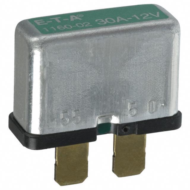
38 Series Circuit with a 12 Volt Source R1 =.5 Ohms R2 = 1 Ohms R3 = 1 Ohms R4 =.5 Ohms Total Resistance = Circuit Amperage = Voltage Drop of R1 = Voltage Drop of R2 = Voltage Drop of R3 = Voltage Drop of R4 = Total Circuit Voltage Drop = Voltage Available to R2 = Voltage Available to R3 = Voltage Available to R4 = Circuit Wattage =
39 Series Circuit with a 12 Volt Source R1 = 5 Ohms R2 = 1 Ohms R3 = 1 Ohms R4 = 5 Ohms Total Resistance = Circuit Amperage = Voltage Drop of R1 = Voltage Drop of R2 = Voltage Drop of R3 = Voltage Drop of R4 = Total Circuit Voltage Drop = Voltage Available to R2 = Voltage Available to R3 = Voltage Available to R4 = Circuit Wattage =
40 Series Circuit with a 12 Volt Source R1 = 20 Ohms R2 = 10 Ohms R3 = 10 Ohms R4 = 20 Ohms Total Resistance = Circuit Amperage = Voltage Drop of R1 = Voltage Drop of R2 = Voltage Drop of R3 = Voltage Drop of R4 = Total Circuit Voltage Drop = Voltage Available to R2 = Voltage Available to R3 = Voltage Available to R4 = Circuit Wattage =
41 Electrical Parts & Testing Tools
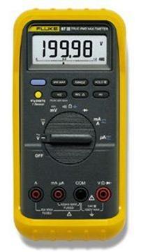
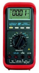
42 Digital Multimeters

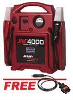
43 Computer Memory Saver


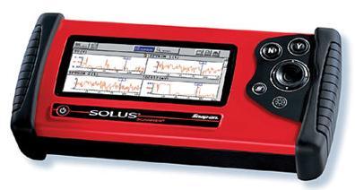
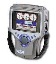
44 Scan Tools

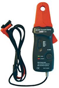
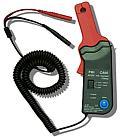
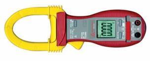
45 Inductive Amps Clamp
46 12 Volt Test Light


47 Relays Use a small amount amperage flow in a coil to pull contacts shut & switch a larger amount of amps
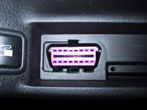
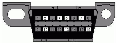
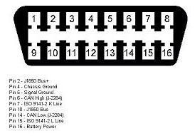
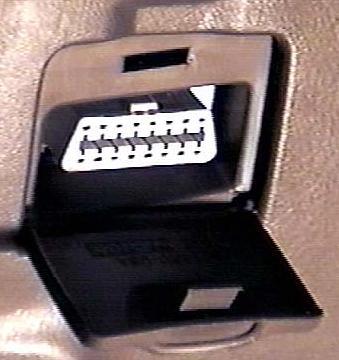
48 Diagnostic Link Connectors
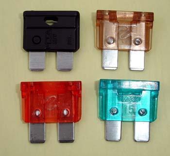
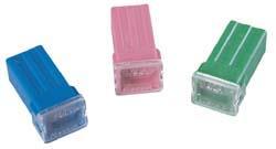
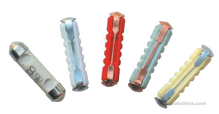

49 Fuses

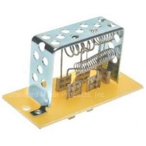
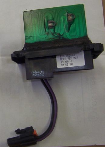
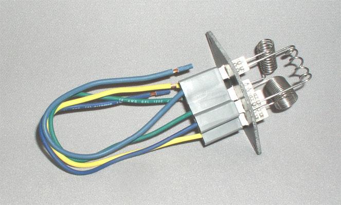
50 Stepped or Tapped Resistors

51 Fused Jumper Wires


52 Solenoids Use a small amount amperage flow in a coil to pull a plunger & switch a larger amount of amps
53 12 Volt Test Light

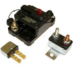

54 Circuit Breakers

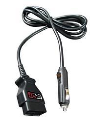
55 Computer Memory Saver
56 Volts Amps Ohms
57 Then: Amperage Increase If: Charging Voltage Increase 12 Volts 6 Ω = 2 Amps 14.2 Volts 6 Ω = 2.36 Amps Volts Amps Ohms
58 Watts Amps Volts
59 Volt Drop R Amps Ohms R
60 Just the Facts Test Preparation
61
62
63
64
65
66
67 a 85 30
68
69
70
71

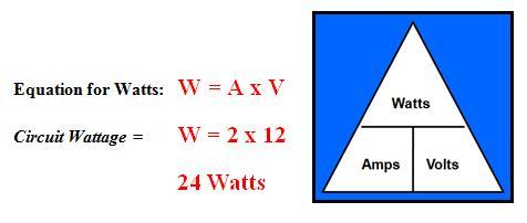
72 W = A x V A = W V V = W A
SECTION 3 BASIC AUTOMATIC CONTROLS UNIT 12 BASIC ELECTRICITY AND MAGNETISM. Unit Objectives. Unit Objectives 2/29/2012
 SECTION 3 BASIC AUTOMATIC CONTROLS UNIT 12 BASIC ELECTRICITY AND MAGNETISM Unit Objectives Describe the structure of an atom. Identify atoms with a positive charge and atoms with a negative charge. Explain
Curriculum. Technology Education ELECTRONICS
 Curriculum Technology Education ELECTRONICS Supports Academic Learning Expectation # 3 Students and graduates of Ledyard High School will employ problem-solving skills effectively Approved by Instructional
What is a multimeter?
 What is a multimeter? A multimeter is a device used to measure voltage, resistance and current in electronics & electrical equipment It is also used to test continuity between to 2 points to verify if
Multimeter Definition
 Multimeter Definition A multimeter is a devise used to measure voltage, resistance and current in electronics & electrical equipment It is also used to test continuity between to 2 points to verify if
Basic Electronics. Chapter 2, 3A (test T5, T6) Basic Electrical Principles and the Functions of Components. PHYS 401 Physics of Ham Radio
 Basic Electrical Principles and the Functions of Components. PHYS 401 Physics of Ham Radio") Basic Electronics Chapter 2, 3A (test T5, T6) Basic Electrical Principles and the Functions of Components Figures in this course book are reproduced with the permission of the American Radio Relay League.
Basic Electronics Chapter 2, 3A (test T5, T6) Basic Electrical Principles and the Functions of Components Figures in this course book are reproduced with the permission of the American Radio Relay League.
Experiment 3 Ohm s Law
 Experiment 3 Ohm s Law The goals of Experiment 3 are: To identify resistors based upon their color code. To construct a two-resistor circuit using proper wiring techniques. To measure the DC voltages and
Electronics for HVACR Technicians
 Electronics for HVACR Technicians SAFETY and HAZARD PREVENTION CIRCUIT PROTECTION Fuses and circuit breakers are used to protect a circuit against over current. The amperage rating of a fuse must not be
+ 24V 3.3K - 1.5M. figure 01
 ELECTRICITY ASSESSMENT 35 questions Revised: 08 Jul 2013 1. Which of the wire sizes listed below results in the least voltage drop in a circuit carrying 10 amps: a. 16 AWG b. 14 AWG c. 18 AWG d. 250 kcmil
ELECTRIC CIRCUITS AND ELECTRONICS
 Circuitos eléctricos y electrónicos ELECTRIC CIRCUITS AND ELECTRONICS Technology, programming and robotics II Electric Circuitos circuits eléctricos and y electronics electrónicos AN ELECTRICAL CIRCUIT
Single-Phase Transformation Review
 Single-Phase Transformation Review S T U D E N T M A N U A L March 2, 2005 2 STUDENT TRAINING MANUAL Prerequisites: None Objectives: Given the Construction Standards manual and a formula sheet, you will
Lab #1 Help Document. This lab will be completed in room 335 CTB. You will need to partner up for this lab in groups of two.
 Lab #1 Help Document This help document will be structured as a walk-through of the lab. We will include instructions about how to write the report throughout this help document. This lab will be completed
AME140 Lab #2 INTRODUCTION TO ELECTRONIC TEST EQUIPMENT AND BASIC ELECTRONICS MEASUREMENTS
 INTRODUCTION TO ELECTRONIC TEST EQUIPMENT AND BASIC ELECTRONICS MEASUREMENTS The purpose of this document is to guide students through a few simple activities to increase familiarity with basic electronics
P2122. P Accelerator Pedal Position Sensor 1 Circuit Low
 Page 1 of 10 Home Account Contact ALLDATA Log Out Help DAN GRIMWOOD DAN GRIMWOOD00002 Select Vehicle New TSBs Technician's Reference Component Search: OK 2006 Dodge Truck RAM 1500 Truck 2WD V8-5.7L VIN
GCSE Electronics. Scheme of Work
 GCSE Electronics Scheme of Work Week Topic Detail Notes 1 Practical skills assemble a circuit using a diagram recognize a component from its physical appearance (This is a confidence building/motivating
REQUIRED SKILLS AND KNOWLEDGE UEENEEE104A. Topic and Description NIDA Lesson CARD #
 REQUIRED SKILLS AND KNOWLEDGE UEENEEE104A KS01-EE104A Direct current circuits T1 Topic and Description NIDA Lesson CARD # Basic electrical concepts encompassing: electrotechnology industry static and current
Team 2228 CougarTech 1. Training L1. Electric Circuits
 Team 2228 CougarTech 1 Training L1 Electric Circuits Team 2228 CougarTech 2 Objectives Understand: Understand the electrical Language Understand the basic components of electric circuits Understand ohms
Basic Electronics. Chapter 2 Basic Electrical Principles and the Functions of Components. PHYS 401 Physics of Ham Radio
 Basic Electronics Chapter 2 Basic Electrical Principles and the Functions of Components Figures in this course book are reproduced with the permission of the American Radio Relay League. This booklet was
BASIC ELECTRICAL AND INSTRUMENTATION DESIGN TRAINING SECTOR / ENGINEERING
 BASIC ELECTRICAL AND INSTRUMENTATION DESIGN TRAINING SECTOR / ENGINEERING TECHNICAL & CERTIFICATE OF ATTENDANCE TRAINING COURSE This five days course covers the electrical principles and components used
FCC Technician License Course
 FCC Technician License Course 2018-2022 FCC Element 2 Technician Class Question Pool Presented by: Tamiami Amateur Radio Club (TARC) WELCOME To the SECOND of 3, 4-hour classes presented by TARC to prepare
AMERITRON SDC-102 Screwdriver Antenna Controller
 AMERITRON SDC-102 Screwdriver Antenna Controller INSTRUCTION MANUAL PLEA S E REA D T H IS M A NU A L BEFORE OP ERA T I N G T H IS EQU IP M EN T! 116 Willow Road Starkville, MS 39759 USA 662-323-8211 Version
Portfolio/ Assessment Package AC/DC ELECTRICAL SYSTEMS CB227-BC00UEN
 Portfolio/ Assessment Package AC/DC ELECTRICAL SYSTEMS CB227-BC00UEN FIRST EDITION, REV. G Amatrol, AMNET, CIMSOFT, MCL, MINI-CIM, IST, ITC, VEST, and Technovate are trademarks or registered trademarks
Basic Circuitry and X ray Production. Lynn C. Sadler, MSRS, R.T.(R)(QM) President, WCEC, Inc.
(QM) President, WCEC, Inc.") Basic Circuitry and X ray Production Lynn C. Sadler, MSRS, R.T.(R)(QM) President, WCEC, Inc. X Ray Production What are X Rays? Where do they come from? What are some characteristics of x radiation? How
Basic Circuitry and X ray Production Lynn C. Sadler, MSRS, R.T.(R)(QM) President, WCEC, Inc. X Ray Production What are X Rays? Where do they come from? What are some characteristics of x radiation? How
UNIVERSITY OF NORTH CAROLINA AT CHARLOTTE Department of Electrical and Computer Engineering
 UNIVERSITY OF NORTH CAROLINA AT CHARLOTTE Department of Electrical and Computer Engineering EXPERIMENT 2 BASIC CIRCUIT ELEMENTS OBJECTIVES The purpose of this experiment is to familiarize the student with
MFJ ENTERPRISES, INC.
 TM Model MFJ-1924 INSTRUCTION MANUAL CAUTION: Read All Instructions Before Operating Equipment! MFJ ENTERPRISES, INC. 300 Industrial Park Road Starkville, MS 39759 USA Tel: 662-323-5869 Fax: 662-323-6551
Transformer circuit calculations
 Transformer circuit calculations This worksheet and all related files are licensed under the Creative Commons Attribution License, version 1.0. To view a copy of this license, visit http://creativecommons.org/licenses/by/1.0/,
SCHEMATIC OF GRAYMARK 808 POWERED BREADBOARD
 SCHEMATIC OF GRAYMARK 808 POWERED BREADBOARD 1a white SW1 white 2a TP1 blue TP2 black blue TP3 TP4 yellow TP5 yellow TP6 4 3 8 7 + D1 D2 D5 D6 C1 R1 TP8 Q1 R3 TP12 2 TP18 U2-0-15V C8 9 C2 + TP15 C5 R12
BME/ISE 3511 Bioelectronics I - Laboratory Exercise #4. Variable Resistors (Potentiometers and Rheostats)
") BME/ISE 3511 Bioelectronics I - Laboratory Exercise #4 Variable Resistors (Potentiometers and Rheostats) Introduction: Variable resistors are known by several names (potentiometer, rheostat, variable resistor,
BME/ISE 3511 Bioelectronics I - Laboratory Exercise #4 Variable Resistors (Potentiometers and Rheostats) Introduction: Variable resistors are known by several names (potentiometer, rheostat, variable resistor,
Basic Electrical Training
 Basic Electrical Training Electricians Tools Explain how various hand tools are used by an electrician Discuss the safe use of hand tools and power tools Perform basic calculations and measurement conversions
8) Name three more types of circuits that we will not study in this class.
 Name three more types of circuits that we will not study in this class.") Name Concepts:( power ) 1) What is power? 2) What are the three equations for electrical power? 3) What are two units for power? 4) What does the power company sell its customers? 5) What is the unit sold
Name Concepts:( power ) 1) What is power? 2) What are the three equations for electrical power? 3) What are two units for power? 4) What does the power company sell its customers? 5) What is the unit sold
Exercise 1: The DC Ammeter
 Exercise 1: The DC Ammeter EXERCISE OBJECTIVE When you have completed this exercise, you will be able to determine current by using a basic meter movement. You will verify ammeter operation by measuring
FC Series Signal Conditioners
 FC Series Signal Conditioners FC-33 DC Selectable Signal Conditioner with 3-way isolation Field configurable input and output ranges of 0-5V, 0-10 V, 0-20 ma and 4-20 ma with 1500 VDC isolation between
DC Circuits, Ohm's Law and Multimeters Physics 246
 DC Circuits, Ohm's Law and Multimeters Physics 246 Theory: In this lab we will learn the use of multimeters, verify Ohm s law, and study series and parallel combinations of resistors and capacitors. For
Syllabus OP49 Test electrical conduction in a variety of materials, and classify each material as a conductor or insulator
 Physics: 14. Current Electricity Please remember to photocopy 4 pages onto one sheet by going A3 A4 and using back to back on the photocopier Syllabus OP49 Test electrical conduction in a variety of materials,
FCC Technician License Course
 FCC Technician License Course 2014-2018 FCC Element 2 Technician Class Question Pool Presented by: Tamiami Amateur Radio Club (TARC) WELCOME To the SECOND of 4, 3-hour classes presented by TARC to prepare
Electronics Technology and Robotics I Week 5 Resistors and Potentiometers
 Electronics Technology and Robotics I Week 5 Resistors and Potentiometers Administration: o Prayer o Turn in quiz o Using two switches, design a circuit that correspond to an AND gate. Resistors: o Function:
Variable Transformers Product Design & Engineering Data
 Variable Transformers Product Design & Engineering Data Product Design & Engineering Data Type 1010B Cutaway General Information STACO ENERGY PRODUCTS CO. is a leading manufacturer of variable transformers,
Basic Electricity 30 Hour - Part 1 Student Workbook Issue: US140/30/2a-IQ-0402A. Written by: LJ Technical Dept
 Basic Electricity 30 Hour - Part Issue: US40/30/a-IQ-040A Copyright 004,. No part of this Publication may be adapted or reproduced in any material form, without the prior written permission of. Written
ET 51 - Electrician Theory Examination Marking Schedule
 ET 51 - Electrician Theory Examination Marking Schedule Notes:1. means that the preceding statement/answer earns 1 mark. 2. This schedule sets out the accepted answers to the examination questions. A marker
AC/DC ELECTRONICS LABORATORY
 Includes Teacher's Notes and Typical Experiment Results Instruction Manual and Experiment Guide for the PASCO scientific Model EM-8656 012-05892A 1/96 AC/DC ELECTRONICS LABORATORY 1995 PASCO scientific
Embedded Systems Analog Electronics
 Embedded Systems Analog Electronics Units physical units = length [meter], mass [kilogram], time [second] force - [Newton]: kg m/s 2 (F=ma) torque - [N m] energy - [joule]: 1N acting through distance of
Design and Technology
 E.M.F, Voltage and P.D E.M F This stands for Electromotive Force (e.m.f) A battery provides Electromotive Force An e.m.f can make an electric current flow around a circuit E.m.f is measured in volts (v).
Circuit Breakers. Excerpt from Master Catalogue. Circuit Breakers. Specifically For You
 Circuit Breakers Excerpt from Master Catalogue Circuit Breakers Specifically For You Hydraulic-magnetic technology ensures reduced nuisance tripping with temperature variance Always holds 00% rated current
TEACHER ASSESSMENT BLUEPRINT ELECTRICAL CONSTRUCTION TECHNOLOGY. Test Code: 5171 Version: 01
 TEACHER ASSESSMENT BLUEPRINT ELECTRICAL CONSTRUCTION TECHNOLOGY Test Code: 5171 Version: 01 Specific Competencies and Skills Tested in this Assessment: OSHA Regulations and Electrical Safety Practices
Potentiometer Tutorial Cornerstone Electronics Technology and Robotics I Week 8
 Potentiometer Tutorial Cornerstone Electronics Technology and Robotics I Week 8 Electricity and Electronics, Section 3.5, Potentiometers: o Potentiometers: A potentiometer is a type of variable resistor
Resistance and Ohm s law
 Resistance and Ohm s law Objectives Characterize materials as conductors or insulators based on their electrical properties. State and apply Ohm s law to calculate current, voltage or resistance in an
Electric Circuits. Alternate Units. V volt (V) 1 V = 1 J/C V = E P /q V = W/q. Current I ampere (A) 1 A = 1 C/s V = IR I = Δq/Δt
 1 V = 1 J/C V = E P /q V = W/q. Current I ampere (A) 1 A = 1 C/s V = IR I = Δq/Δt") Electric Circuits Quantity Symbol Units Charge Q,q coulomb (C) Alternate Units Formula Electric Potential V volt (V) 1 V = 1 J/C V = E P /q V = W/q Work, energy W, E P joule (J) W = qv E P = qv Current
Electric Circuits Quantity Symbol Units Charge Q,q coulomb (C) Alternate Units Formula Electric Potential V volt (V) 1 V = 1 J/C V = E P /q V = W/q Work, energy W, E P joule (J) W = qv E P = qv Current
Experiment (1) Principles of Switching
 Principles of Switching") Experiment (1) Principles of Switching Introduction When you use microcontrollers, sometimes you need to control devices that requires more electrical current than a microcontroller can supply; for this,
Experiment (1) Principles of Switching Introduction When you use microcontrollers, sometimes you need to control devices that requires more electrical current than a microcontroller can supply; for this,
ELEXBO. Electrical - Experimentation Box
 ELEXBO Electrical - Experimentation Box 1 Table of contents 2 Introduction...3 Basics...3 The current......4 The voltage...6 The resistance....9 Measuring resistance...10 Summary of the electrical values...11
DIGITAL AND ANALOGUE MULTIMETERS
 This ebook shows you how to TEST COMPONENTS. To do this you need "TEST GEAR." The best item of Test Gear is a MULTIMETER. It can test almost 90% of all components. And that's what we will do in this ebook:
1-1. Kirchoff s Laws A. Construct the circuit shown below. R 1 =1 kω. = 2.7 kω R 3 R 2 5 V
 Physics 310 Lab 1: DC Circuits Equipment: Digital Multimeter, 5V Supply, Breadboard, two 1 kω, 2.7 kω, 5.1 kω, 10 kω, two, Decade Resistor Box, potentiometer, 10 kω Thermistor, Multimeter Owner s Manual
ASE 6 - Electrical Electronic Systems. Module 3 Properties of Electricty
 Electronic Systems Module 3 Acknowledgements General Motors, the IAGMASEP Association Board of Directors, and Raytheon Professional Services, GM's training partner for GM's Service Technical College wish
(%) ex Blue-Black-Brown-Gold 600 Ω ± 5% ± 30 1
 ex Blue-Black-Brown-Gold 600 Ω ± 5% ± 30 1") ** Disclaimer: This Lab is not to be copied, duplicated, and/or distributed, in whole or in part, unless approval is received from the University of Colorado at Colorado Springs Physics Department AND
** Disclaimer: This Lab is not to be copied, duplicated, and/or distributed, in whole or in part, unless approval is received from the University of Colorado at Colorado Springs Physics Department AND
Glossary 78 LIFETIME LIMITED WARRANTY. GREENLEE Phone: (International)
") A AC alternating current, or current that reverses direction at regular rate. When graphed, alternating current can appear as a series of curves, squares, or triangles. The shape of the graph is referred
A AC alternating current, or current that reverses direction at regular rate. When graphed, alternating current can appear as a series of curves, squares, or triangles. The shape of the graph is referred
The Art of Electrical Measurements
 The Art of Electrical Measurements Purpose: Introduce fundamental electrical test and measurement tools and the art of making electrical measurements. Equipment Required Prelab 1 Digital Multimeter 1 -
Chapter 3. Electricity, Components and Circuits. Metric Units
 Chapter 3 Electricity, Components and Circuits Metric Units 1 T5B02 -- What is another way to specify a radio signal frequency of 1,500,000 hertz? A. 1500 khz B. 1500 MHz C. 15 GHz D. 150 khz T5B07 --
Electronics Review 1 Cornerstone Electronics Technology and Robotics II Week 1
 Electronics Review 1 Cornerstone Electronics Technology and Robotics II Week 1 Administration: o Prayer o Welcome back o Review Quiz 1 Review: o Reading meters: When a current or voltage value is unknown,
CONTENTS. Analogue Multimeter Audio Stages Batteries - testing Burnt Resistor Buying A Multimeter Capacitors Capacitors - decoupling caps
 This ebook shows you how to TEST COMPONENTS. To do this you need "TEST GEAR." The best item of Test Gear is a MULTIMETER. It can test almost 90% of all components. And that's what we will do in this ebook:
2007 The McGraw-Hill Companies, Inc. All rights reserved.
 Chapter 2 Resistors Topics Covered in Chapter 2 2-1: Types of Resistors 2-2: Resistor Color Coding 2-3: Variable Resistors 2-4: Rheostats and Potentiometers 2-5: Power Ratings of Resistors 2-6: Resistor
Chapter 12 Electric Circuits
 Conceptual Physics/ PEP Name: Date: Chapter 12 Electric Circuits Section Review 12.1 1. List one way electric current is similar to water current and one way it is different. 2. Draw a circuit diagram
ELECTRONICS AND ELECTRICITY
 INTRODUCTION ELECTRONICS ND ELECTRICITY The science of Electronics and Electricity makes a very important contribution to our everyday existence. Electricity is concerned with the generation, transmission
Experiment 6. Electromagnetic Induction and transformers
 Experiment 6. Electromagnetic Induction and transformers 1. Purpose Confirm the principle of electromagnetic induction and transformers. 2. Principle The PASCO scientific SF-8616 Basic Coils Set and SF-8617
Practical Tricks with Transformers. Larry Weinstein K0NA
 Practical Tricks with Transformers Larry Weinstein K0NA Practical Tricks with Transformers Quick review of inductance and magnetics Switching inductive loads How many voltages can we get out of a $10 Home
Prof. Hala J. El Khozondar Spring 2016
 Technical English Unit 43 professional english Current, voltage and resistance Prof. Hala J. El Khozondar Spring 2016 Content A. Electric current B. Voltage and resistance C. Electrical power 2 A. Electric
Chapters 11 & 12 Electronic Controls & Automation
 Chapters 11 & 12 Electronic Controls & Automation Use the Textbook Pages 255 297 to help answer the questions Why You Learn So Well in Tech & Engineering Classes 1. All control systems have and devices.
Experiment 7: PID Motor Speed Control
 Experiment 7: PID Motor Speed Control Introduction The error output, Ve, of the tachometer circuit from experiment 6 will be connected to the input of a PID controller. The output of the PID controller,
PHY 132 LAB : Ohm s Law
 PHY 132 LAB : Ohm s Law Introduction: In this lab, we look at the concepts of electrical resistance and resistivity. Text Reference: Wolfson 27:2-3. Special equipment notes: 1. Note the tips on wiring
ECE 2010 Laboratory # 3 J.P.O Rourke
 ECE 21 Laboratory # 3 J.P.O Rourke Prelab: Simulate all the circuits in this Laboratory. Record the simulated results for each part of the lab. Your Prelab is due at the beginning of lab and will be checked
Meters and Test Equipment
 Installation Knowledge and Techniques Meters and Test Equipment OBJECTIVES Meters and Test Equipment DMM s and VOM s Describe the difference between a DMM and a VOM. Describe the methods for measuring
Contents. Acknowledgments. About the Author
 Contents Figures Tables Preface xi vii xiii Acknowledgments About the Author xv xvii Chapter 1. Basic Mathematics 1 Addition 1 Subtraction 2 Multiplication 2 Division 3 Exponents 3 Equations 5 Subscripts
CURRENT ELECTRICITY. 1. The S.I. unit of power is (a) Henry (b) coulomb (c) watt (d) watt-hour Ans: c
 Henry (b) coulomb (c) watt (d) watt-hour Ans: c") CURRENT ELECTRICITY 1. The S.I. unit of power is (a) Henry (b) coulomb (c) watt (d) watt-hour 2. Electric pressure is also called (a) resistance (b) power (c) voltage (d) energy 3. The substances which
CURRENT ELECTRICITY 1. The S.I. unit of power is (a) Henry (b) coulomb (c) watt (d) watt-hour 2. Electric pressure is also called (a) resistance (b) power (c) voltage (d) energy 3. The substances which
Industrial Technology Electronics Technologies
 2010 HIGHER SCHOOL CERTIFICATE EXAMINATION Industrial Technology Electronics Technologies Total marks 40 General Instructions Reading time 5 minutes Working time 1 1 hours 2 Write using black or blue pen
Electronics & Computer Systems. ATASA 5 th. Please Read The Summary. ATASA 5 TH Study Guide Chapter 22 Pages Electronics & Computer Systems
 ATASA 5 TH Study Guide Chapter 22 Pages 670 703 95 Points Please Read The Summary 1. Electronics is the technology of electricity and all of the basic laws of electricity also apply to all electronic controls.
Workshop 9: First steps in electronics
 King s Maths School Robotics Club Workshop 9: First steps in electronics 1 Getting Started Make sure you have everything you need to complete this lab: Arduino for power supply breadboard black, red and
Application Note CTAN #305
 Application Note CTAN #305 This Application Note is pertinent to the Unidrive SP, GP20 and Affinity Families Creating a Custom Motor Overtemperature Trip The Unidrive SP has facilities on Analog Input
The topics in this unit are:
 The topics in this unit are: 1 Static electricity 2 Repulsion and attraction 3 Electric circuits 4 Circuit symbols 5 Currents 6 Resistance 7 Thermistors and light dependent resistors 8 Series circuits
TRANSFORMER OPERATION
 Chapter 3 TRANSFORMER OPERATION 1 A transformer is a static device (no moving parts) used to transfer energy from one AC circuit to another. This transfer of energy may involve an increase or decrease
Creating Electrical Designs
 C h a p t e r 2 Creating Electrical Designs In this chapter, we will learn the following to World Class standards: Understanding Control and Power Circuits Drawing the Control Circuit Selecting the Pushbutton
TOA PROFESSIONAL POWER AMP
 Operating Instruction Manual TOA PROFESSIONAL POWER AMP Model P-150M, P-300M TOA ELECTRIC CO, LTD. KOBE, JAPAN Contents Precautions... 2 General Description... 2 Features... 3 Specifications... 4~5 Performance
Exercise 1: The Rheostat
 Potentiometers and Rheostats DC Fundamentals Exercise 1: The Rheostat EXERCISE OBJECTIVE When you have completed this exercise, you will be able to vary current by using a rheostat. You will verify your
Inductors and Transformers
 MEHRAN UNIVERSITY OF ENGINEERING AND TECHNOLOGY, JAMSHORO DEPARTMENT OF ELECTRONIC ENGINEERING ELECTRONIC WORKSHOP # 05 Inductors and Transformers Roll. No: Checked by: Date: Grade: Object: To become familiar
OPERATING MANUAL SERIES R B F BRUSHLESS RACK SYSTEM
 OPERATING MANUAL SERIES R B F BRUSHLESS RACK SYSTEM Version 3.0 (European version 1.3) This is a general manual describing a series of racks receiving Servo Amplifiers having output capability suitable
BASIC ELECTRONICS PROF. T.S. NATARAJAN DEPT OF PHYSICS IIT MADRAS LECTURE-2 ELECTRONIC DEVICES -1 RESISTOR, IDEAL SOURCE VOLTAGE & CAPACITOR
 BASIC ELECTRONICS PROF. T.S. NATARAJAN DEPT OF PHYSICS IIT MADRAS LECTURE-2 ELECTRONIC DEVICES -1 RESISTOR, IDEAL SOURCE VOLTAGE & CAPACITOR In the last lecture we saw the importance of learning about
Central Electronics Model 600L Linear Amplifier
 INTRODUCTION This manual has been reproduced by James Lawrence, NA5RC, a 600L owner. Text no longer applicable such as insurance claim with the carrier has been deleted. Some capitalization and grammar
CALRAD MINIATURE MULTI-CLICK DUAL CONTROLS 40 STEP P.C. MOUNT 11
 25 Series - Potentiometers Audio & Linear SUB-MINIATURE VOLUME CONTROLS Linear taper, extremely smooth for quiet operation. 1 /2" dia. fits into 1 /4 hole. Shaft 3 /16" dia. Thread length 7 /32", shaft
Definitions of Technical Terms
 Definitions of Technical Terms Terms Ammeter Amperes, Amps Band Capacitor Carrier Squelch Diode Dipole Definitions How is an ammeter usually connected = In series with the circuit What instrument is used
CALRAD 25 series - potentiometers
 25 series - potentiometers audio /linear SUB-MINIATURE VOLUME CONTROLS Linear taper, extremely smooth for quiet operation. 1 2" dia. fits into 1 4" hole. Shaft 3 16" dia. Thread length 7 32", shaft length
Home Map Projects Construction Soldering Study Components 555 Symbols FAQ Links
 Home Map Projects Construction Soldering Study Components 555 Symbols FAQ Links Circuit Symbols Wires Supplies Output devices Switches Resistors Capacitors Diodes Transistors Audio & Radio Meters Sensors
Know and understand you and your co-workers competence level before opening a live panel to diagnose
 MARCH 2014 BASIC ELECTRICAL UNDERSTANDING MARCH 2014 SAFETY FIRST Always use extreme caution when working around electricity A electrical shock can kill you! The purpose of this module is to: Develop basic
Lesson 3: Electronics & Circuits
 Lesson 3: Electronics & Circuits Preparation for Amateur Radio Technician Class Exam Topics Review Ohm s Law Energy & Power Circuits Inductors & Inductance Capacitors & Capacitance Analog vs Digital Exam
Introduction to Electronic Equipment
 Introduction to Electronic Equipment INTRODUCTION This semester you will be exploring electricity and magnetism. In order to make your time in here more instructive we ve designed this laboratory exercise
Product overview. Features. Product specifications. Order codes. 1kΩ Resistance Output Module
 Product overview The AX-ROM135 and the AX-ROM1000 Modules enable an Analogue, Pulse or Floating point signal and convert to either a 0-135Ω or a 1KΩ Proportional Resistive output signal. The output resistance
Introduction. A closed loop of wire is not an electrical circuit, a circuit requires
 The Law of Charges Opposite charges attract like charges repel Lines of force can never cross each other The values are equal but the effect is opposite Strength of the attraction is exponential to its
F O R T H E L O V E O F M U S I C LP100 OWNER'S MANUAL AND INSTALLATION GUIDE INTRODUCTION
 F O R T H E L O V E O F M U S I C LP100 OWNER'S MANUAL AND INSTALLATION GUIDE INTRODUCTION You have purchased an amplifier that leads the way with sound quality, reliability, and features. These high performance
REPAIRING THE RM KL400 LINEAR AMPLIFIER.
 REPAIRING THE RM KL400 LINEAR AMPLIFIER. Les Carpenter G4CNH December 2012 Page 1 of 20 The following is a step by step guide to fixing your KL400 amplifier. Each part will be individually tested up to
SUBELEMENT T5 Electrical principles: math for electronics; electronic principles; Ohm s Law 4 Exam Questions - 4 Groups
 SUBELEMENT T5 Electrical principles: math for electronics; electronic principles; Ohm s Law 4 Exam Questions - 4 Groups 1 T5A Electrical principles, units, and terms: current and voltage; conductors and
MECHANICS WAVEFORM. In this article I m going to take THE OF A
 THE MECHANICS OF A WAVEFORM BY JORGE MENCHU Every time a waveform moves up or down, something in the circuit that s being tested has changed. Learning to identify the factors that shape a waveform is a
Current Draw (Circuit breakers and fuses blow. Burning smell or smoke)
") T r o u b l e s h o o t i n g Current Draw (Circuit breakers and fuses blow. Burning smell or smoke) Excessive current without signal present Fast current draw Medium current draw Slow current draw Runaway
T r o u b l e s h o o t i n g Current Draw (Circuit breakers and fuses blow. Burning smell or smoke) Excessive current without signal present Fast current draw Medium current draw Slow current draw Runaway
SUBELEMENT T6 Electrical components: semiconductors; circuit diagrams; component functions 4 Exam Questions - 4 Groups
 SUBELEMENT T6 Electrical components: semiconductors; circuit diagrams; component functions 4 Exam Questions - 4 Groups 1 T6A Electrical components: fixed and variable resistors; capacitors and inductors;
MODEL INFORMATION. Model AWRMS TM 200. Automated Winding Resistance Measurement System
 Model AWRMS TM 200 Automated Winding Resistance Measurement System Currents up to 200A for performing Winding Resistance and Heat Run Tests. Heavy Duty Protection Circuit. Accuracy with Four Wire Measurements
ECE 2010 Laboratory # 3 J.P.O Rourke
 ECE Laboratory # 3 J.P.O Rourke Prelab: Simulate the circuits in Part through 4 of this Laboratory. Use the given Multisim circuits that follow Lab 3 on the Website. You do not need to look up any sensors