Lab #1 Help Document. This lab will be completed in room 335 CTB. You will need to partner up for this lab in groups of two.
|
|
|
- Kelly Hutchinson
- 5 years ago
- Views:
Transcription


1 Lab #1 Help Document This help document will be structured as a walk-through of the lab. We will include instructions about how to write the report throughout this help document. This lab will be completed in room 335 CTB. You will need to partner up for this lab in groups of two. This lab will require the use of the following pieces of equipment: DC power supply DMM

2 Bread Board 5 Resistors: Resistance Value in ohms (Ω) Color Bands 33 Ω Orange-orange-black 100 Ω Brown-black-brown 330 Ω Orange-orange-brown 1.0 k Ω Brown-black-red 3.3 k Ω Orange-orange-red There are 7 steps in this lab. It is best for this lab to do them in the order that they are written. 1. First measure the resistance of each of your resistors using the DMM. Determine how close it is to its rated value, and whether it is within its rated tolerance. For this part of the lab, you ll be measuring the values of the 5 resistors using the DMM. The breadboard will be used throughout the lab to hold and connect the resistors. Before you can measure the values of your resistors, you will need to configure your DMM (Digital Multimeter) to make resistance measurements. What follows is an explanation of how to configure the DMM for making certain types of measurements:

3 How to use the DMM There are 4 holes located in the upper left corner of the DMM. The red and black leads are inserted here. The configuration of the leads depends on the measurement you are taking. When measuring voltage and resistance, the DMM needs to have its leads configured in the following manner. The black lead needs to be inserted in the bottom left hole labeled COM. The red lead needs to be inserted in the upper left hole labeled with a V and Ω (Omega symbol).
4 When measuring current, the DMM needs to have the black lead inserted in the bottom left hole labeled COM and the red lead inserted in either the top right (labeled 10 A) or bottom right (labeled 100 ma) hole. Unless the lab requires that 10 or more Amps of power be measured (which is usually not the case), assume that for measuring current the red lead will always be inserted in the bottom right hole labeled 100 ma. There are 5 buttons located beneath the display that activate different measurement settings. The top three from left to right are DC Voltage, DC Current, and Resistance. The bottom two buttons are AC Voltage and AC Current. After configuring the leads, you must select the setting by pressing its respective button if you want to correctly measure anything.

5 The DMM has the ability to automatically adjust its unit resolution. To enable this ability, the word AUTO must be shown in the top right corner of the display. If this is not the case, press the grey button labeled AUTO which is the second button down located beneath the display. If AUTO is not active, some of your measurements may yield an O.L on the screen. This stands for OVERLOAD and happens when the measurement is too big to be accommodated by the screen on its current unit resolution setting. You can manually adjust the unit resolution by pressing the grey up and down arrow buttons located beneath the display.

6 Back to Step 1 Based on the information you just read, you will need to place the red lead in the V/ Ω hole (upper left) and the black lead in the COM hole (lower left). You will also need to press the Ω button located beneath the DMM display and ensure that the DMM is set to AUTO so that it automatically adjusts the units. To measure the value across the resistors, place the one you are measuring in the breadboard. It is better to do this than to hold the DMM leads on both ends of the resistor since your body has a resistance and the reading you get will be the resistance for your resistor and your body being connected in parallel. ORIENTATION ON THE BREAD BOARD IS IMPORTANT! What follows is an explanation of how to properly place resistors on a breadboard: How to use a bread board A breadboard is a device that allows you to make circuits without soldering the leads. The breadboards used in this lab have 3 sets of connections composed of columns of connection holes. The first set is in columns of two holes. The second and third sets both contain columns of five holes. The sets do not connect to each other so connections made between sets are okay. Rows are not connected to each other along their holes while columns are. In other words, all holes within a column are connected together while all holes within a row are independent. Because of this, you NEVER place a component like a resistor such that two or more of its leads are in the same column. This will create a short circuit and can burn out the power supply. You can place one lead each from different components in the same column to connect them. For example, you can place one lead from a 100 ohm resistor and one lead from a 330 ohm resistor in the same column in order to connect them. If their other leads connect to differing columns, the resistors will be connected in series. If their other leads connect in the same column, the resistors are connected in parallel.


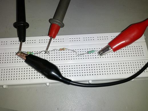
7 Back to Step 1 Based on the instructions above, you will need to place the resistors in the breadboard by placing both leads in the same row, but in different columns. THIS IS VERY IMPORTANT! Current takes the path of least resistance. If both leads are in the same set and the same column, the test current being generated by the DMM will go through the bread board wiring instead of the resistor because it has less resistance. The result is a short circuit which at best will give you a wrong reading and at worst will blow the DMM s fuse rendering it unusable until the fuse is replaced. To measure the resistance across each resistor, simply place the black lead of the DMM on one of the resistors leads and the red lead on the other as shown below.
8 The reading on the display is your resistance. Take care to note the units that the display is using. Just the Ω symbol means ohms, k Ω means kilohms (1,000 ohms), and M Ω means megohms (1,000,000 ohms). Note: If the DMM number reading keeps changing, just pick one that shows up a lot. If the reading continues to steadily increase or decrease, use the first reading before it begins to decrease/increase steadily. The next part of step 1 is to determine how far the measured values you got are from the rated values (known as percent difference) and whether or not your resistors are within tolerance. To determine the percent difference between your measured and rated resistance values, use the following formula: [(MV RV)/RV] * 100 where MV = Measured Value RV = Rated Value To determine if your resistors are within tolerance, look at the 4 th band after the first 3. This band will either be a gold band, silver band, or no band. Gold means the tolerance is +-5%. Silver means the tolerance is +-10%. No band (only 3 instead of 4 on the resistor) means that the tolerance is +-20%. Example, if your resistor has a gold band and your calculated percent difference is -3.45%, then your resistor is within tolerance. If you calculated 6.78%, then your resistor is out of tolerance. Lab Report For your lab report, you will need to record the steps you took to measure the resistors, the resistances that you measured, the percent difference equation and its components, your calculated percent difference values, and whether or not the resistors were within tolerance. Be sure to specify the units with all resistance values. You can use pictures to describe how you made measurements. For example, to describe how you set up the DMM you can say: I configured the DMM to make voltage measurements, and follow that with a picture or diagram of the DMM showing the red and black leads in the proper holes along with the screen on showing the units for resistance. Then for the actual measurements, you could say something like: Measurements were taken as shown in this picture/diagram, and then have a picture showing a resistor on a breadboard with the red lead of the DMM on one side and the black lead on the other. You could also use a written description, though image descriptions may be simpler to create especially if pictures are taken of the steps during the lab process. Regardless of whether you use images or written descriptions, ensure that the description is complete, meaning another person who hasn t taken this lab and doesn t know how to set up the equipment could use your description to make the same measurements. Also, keep digital copies of this and future lab reports in case the same measurement is made during a future lab. You can use the descriptions from this lab for those reports as well as long as they don t have extra bits that need to be documented.
9 If measurements are made multiple times during a lab, you only have to describe the first measurement with the detail indicated above. All other measurements of the same type can refer to this description. For example, if you measure resistance in part 1 and part 6, you only have to describe the method of making the measurements and setting up the DMM in part 1. You can refer back to them in part 6. You do still need to include any measured values however for both parts. As far as recording your data is concerned, include the following information: Include all used equations. This part of the lab only had one, so include it: [(MV RV)/RV] * 100 where MV = Measured Value RV = Rated Value As with measurement descriptions, equations that are used more than once in the lab do not need to be double stated. State the equation in the lab report where it occurs first and refer back to it for later parts of the lab. Remember that you do still need to include calculated values for both parts. Organizing data in a table format makes it easy to read so, while it is not a requirement, it is a recommendation. Be sure to label the data accordingly and include the units (if any). If the units aren t included in the label or if you aren t using a table to show your data, then each number will require its respective units to be included with it. If the units aren t shown in a way that clearly indicates which numbers they belong to, then as TA's we can't be sure what the numbers are for so you will lose some credit. Rated Value (ohms) Measured Value (ohms) Calculated % difference Tolerance of resistor (%) Is it within tolerance? No Yes Yes 1, Yes 3,300 3, Yes After you have checked your resistors to ensure that they are within tolerance and are the correct values, do the following to observe the relationships described by Ohm's law: 2. Set the DC power supply to a voltage between +3V and +5V; be sure to record the voltage you Since this is likely your first time using these DC power supplies, let's go over some brief setup instructions to ensure the proper function of the power supply. How to use the DC Power Supply The DC Power Supply has three power outputs. The two left-most have 3 output connections (black, green, and red) and are for the variable supplies which are controlled with the current and voltage knobs. The right most output (only has black and red connectors) is for a fixed 5V 3A supply of power.
.")

10 We will be using the middle output set for this lab. The proper configuration of the DC Power supply for this lab is as follows. Make sure both of the buttons in the middle of the device between the two variable supplies are out not in (set to independent). Make sure that your black lead is connected to the green connector of the middle output and that your red lead is connected to the red connector of the middle output. Also, make sure that there is either a wire or a metal bar connecting the black and green connectors together. If there is not a connection between the green and black connectors and/or if the green is connected instead to the red connector, disconnect the red and green connectors and then connect the green and black connectors.

11 Before use, you must also turn the rightmost current knob greater than half-way up and turn the rightmost voltage knob such that the output voltage is the value indicated by the lab exercise. Back to Step 2 Once you've ensured that your DC power supply is set up as indicated by the above instructions, turn the right-most knob for voltage until it's output reads between 3 and 5 volts. Lab Report For this part on your lab report, all you need to do is state that you, set the DC power supply to output a voltage of x, where x is the voltage you set. For example, a voltage of 4.8V. 3. Measure the current through the circuit with each resistor, in turn, connected (one at a time) to the power supply. Determine how close the actual (measured) current is to the current predicted by Ohm's law. Draw a graph of the actual results compared to the predicted results. Determine the percent difference for each measurement. For this part of the lab, you will first place each resistor, one at a time, on the breadboard and measure the current going through it. To measure current, follow the procedure described below: Measuring Current Through a Resistor To measure the DC current through a resistor, you will need the DMM and the DC Power supply. First, if you haven't already done so, make sure that the DC power supply is correctly configured and set the voltage to the value indicated in the lab using the rightmost voltage knob (step 2 of the lab). Also configure the DMM for DC current measurement by placing the leads in the correct holes and selecting the DC current (not AC current) setting.
12

13 Connect the black leads of the DMM and the DC Power Supply together. Then connect the red lead of the DC Power supply to one lead of the resistor and the red lead from the DMM to the other lead of the resistor. This configuration places the DMM in series with the resistor allowing it to measure current. Back to Step 3 After making and recording the current measurements for the 5 resistors, calculate the current you would expect to get from your set voltage using ohm's law: I = V/R where I = current in amps V = voltage in volts R = resistance in ohms (use the rated resistance value of the resistor, not the one you measured earlier in part 1 of the lab). BE CAREFUL HERE! The DMM will likely make the measurements in millamps, not amps, if it is set to AUTO. Be sure to make appropriate conversions before comparing between these measured results and the calculated ones (1 amp = 1,000 millamps). Take the measured and calculated values and graph them. Microsoft Excel can be used for this and the graph inserted into your lab report. Now take the measured and calculated current values and determine the percent difference between the measured and expected values using the percent difference equation with the following variables: [(MC CC)/CC] * 100 where MC = Measured Current CC = Calculated Current
14 Lab Report For your lab report for this step, you will need to record the steps you took to measure the current through the resistors, your measured values for current through the 5 resistors, your calculated expected current values, the graph comparing measured to calculated current values, and the percent difference values. Be sure to specify the units with all current values (amps). You can use pictures to describe how you made measurements. For example, for setting up the DMM you can say: I configured the DMM to make current measurements, and follow that with a picture or diagram of the DMM showing the red and black leads in the proper holes along with the screen on showing units for current. Then for the actual measurements, you could say something like: Measurements were taken as shown in this picture/diagram, and then have a picture showing a resistor on a breadboard with the red lead of the DMM on one side, the red lead of the DC power supply on the other side of the resistor, and the black leads connected together. You could also use a written description, though image descriptions may be simpler to create especially if pictures are taken of the steps during the lab process. Regardless of whether you use images or written descriptions, ensure that the description is complete, meaning another person who hasn t taken this lab and doesn t know how to set up the equipment could use your descriptions to take the same measurements. Also, keep digital copies of this and future lab reports in case the same measurement is made during a future lab. You can use the descriptions from this lab for those reports as well as long as they don t have extra bits that need to be documented. As far as recording your data is concerned, include the following information: Include all used equations. This part of the lab had two: ohms law and the percent difference equation, so include: I = V/R where I = current in amps V = voltage in volts R = resistance in ohms And (you don t have to include the % difference equation since you used it before, however you do need to at least refer to the equation you reported in part 1 of the lab. Say something like, used % difference equation from part one to calculate the following results. Be sure to include the numbers you used for calculation as well as the answers you got as well as the units of all of those numbers.) [(MC CC)/CC] * 100 where MC = Measured Current CC = Calculated Current Include the graph that you made that compares the measured to the expected currents.
15 Series 1 is for measured values Series 2 is for calculated values (be sure to label or identify which series is which. Without that, your TA s can t tell and you will lose some credit.) Organizing data in a table format makes it easy to read. Be sure to label the data accordingly and include the units (if any). If the units aren t included in the label, then each number will require its respective units to be included with it. If this isn't done one of the two ways mentioned above, then as TA's we can't be sure what the numbers are for so you will lose some credit. (In this case, units are likely to be in millamps or thousandths of an amp). Based on a voltage of 4.8V Resistor value (ohms) Measured Value Calculated Value Calculated % difference (millamps) (millamps) , , Decrease the voltage by 1 Volt and repeat the procedure above. Did the current go up or down? Were the results as you would have expected? This part is pretty self-explanatory. Simply reduce the voltage by 1 volt and repeat the same procedures for measuring current, calculating expected current, graph the new measured and calculated currents, and calculate the percent differences between the new measured and calculated currents.
16 Lab Report For your lab report for this step, you do not need to explain how you made measurements since they are the same steps that you used above. You do need to state that you reduce the voltage by 1 volt to x (your new voltage which needs to be included here as well) and you need to state all measurements, calculated values, graphs, and other data that part 3 required you to make. Example Voltage of 3.8V (which is 1 volt less than the previous example voltage of 4.8V). This step of the lab also asks you if the current went up or down and if these results are what you expected. State whether the current went up or down from step 3 to step 4 and if that is what you expected to happen. Explain why you did or did not expect the increase or decrease in current. As far as recording your data is concerned, include the following information: Include all used formulas. This part of the lab had two: ohms law and the percent difference equation, so include: I = V/R where I = current in amps V = voltage in volts R = resistance in ohms and [(MC CC)/CC] * 100 where MC = Measured Current CC = Calculated Current Include the graph that you made that compares the new measured and expected currents. Also remember to label or specify which line is measured current and which is calculated. Remember to label your data and include the units (if any). If the units aren t included in the label, then each number will require its respective units to be included with it. If this isn't done one of the two ways mentioned above, then as TA's we can't be sure what the numbers are for so you will lose some credit. Based on a voltage of 3.8V Resistor value (ohms) Measured Value Calculated Value Calculated % difference (millamps) (millamps) 33 xxxx xxxx xxxx 100 xxxx xxxx xxxx 330 xxxx xxxx xxxx 1,000 xxxx xxxx xxxx 3,300 xxxx xxxx xxxx
17 To observe the effects of combining resistors in series, do the following: 5. Set the DC power supply to +5V; connect a 330Ω resistor and measure the current. For this part, set the power supply to 5V. Then place a 330 ohm resistor on your breadboard and measure the current going through it. If you need some help with this part, refer to step 3's instructions on using the DC power supply and measuring current. Lab Report For this part of the lab report, you need to state that you set the DC power supply to +5V DC. You also need to state that you measured the current through the 330 ohm resistor using steps that you described earlier in the report (again, you don't have to double record how you make a measurement within the same report if you've done it before. Simply refer to it when you state that you made the measurement). Also state the value of the current that you measured through the 330 ohm resistor. 6. Now add a 1.0kΩ resistor in series with the 330Ω resistor and measure the current. Did the current go up or down? Calculate the expected current for the series combination, and compare this value to the measured current. Were the results as expected? For this part of the lab, you first need to add a 1kohm resistor in series with the 330 ohm resistor. Please refer back to step 1 s breadboard diagrams if you need some help with this. Now, measure the current across both resistors. This works the same was as with only one resistor except that the red lead from the DMM is on the open end of one resistor and the red lead from the DV Power supply is on the open end of the other resistor. DON T connect either red lead in the center between the two resistors. This will give you an incorrect reading. Next, you need to calculate the expected current you would get from this resistor circuit. To do that, you need to find the total resistance and then use that as the resistance value in ohm s law. To find total resistance in a series circuit, you would use the following equation: Rt = R1 + R2 + R3 + where Rt = Total Resistance R1 = Resistance of first resistor (use rated values not measured values for these) R2 = Resistance of second resistor R3 = Resistance of third resistor Since you only have 2 resistors, you would only need Rt = R1 + R2. Next, you would plug that into I = V/R where R would be equal to Rt.
18 Lab Report For this part of the lab report, you need to state that you added a 1kohm resistor in series with the 330 ohm resistor. You need to state whether the current went up or down from the current through just the 330 ohm resistor in step 5. You need to show your calculations for the current through both resistors and your comparison of the calculated vs. the measured values (this can be a written comparison). You need to state if the results were expected or not and why. For data, include the formulas you used: Rt = R1 + R2 + R3 + where Rt = Total Resistance R1 = Resistance of first resistor (use rated values not measured values for these) R2 = Resistance of second resistor R3 = Resistance of third resistor and I = V/R where I = current in amps V = voltage in volts R = resistance in ohms Also remember to include your measured and calculated current values. 7. Now add a 100Ω resistor in series with the other two. Measure the voltage drop across each resistor and compare to what you would expect using the voltage divider rule. Does the sum of the voltage drops equal the applied voltage? Would you expect it to? For this part of the lab, first connect a 100 ohm resistor in series with the 330 and 1,000 ohm resistors. Next, you ll need to set up the DMM to make DC voltage measurements and then measure the voltage drops across each individual resistor. Instructions on how to do this are provided below: How to measure the voltage drop across resistors that are in series To measure the voltage drop across a resistor that is in series with other resistors or components, you will need the DMM and the DC Power supply. First, make sure that the DC power supply is correctly configured and set the voltage to the value indicated in the lab using the rightmost voltage knob. Also configure the DMM for DC voltage measurement by placing the leads in the correct holes and selecting the DC voltage (not AC voltage) setting.
19 Connect the red lead from the DC power supply to one end of the circuit and the black lead to the other. In order to measure the voltage drop across a single resistor, place the red lead and black leads of the DMM on opposite sides of the resistor being measured such that the red lead of the DMM is closest to the red lead from the DC power supply and the black lead of the DMM is closest to the black lead of the DC power supply.
20

21 The voltage shown on the DMM display is the voltage drop across that resistor. To measure the voltage drop across another resistor, simply connect the DMM leads to that resistor in the same way that you did to the first.

22 Then
23 Back to Part 7 Next, you ll need to use the voltage divider rule to calculate the expected voltage drops across those 3 resistors. The instructions for how to do that are as follows: How to Calculate Voltage Drop across a Series Circuit To calculate voltage drop across a resistor in a series circuit, use the following equation: Vout = Vin * ( Ri / (R1 + R2 + R3 + )) where Vout = the voltage drop of the resistor Vin = the input voltage from the power supply Ri = the resistance of the resistor (as printed on the resistor) (R1 + R2 + R3 + ) = the total resistance of the series circuit For example, if we had a series circuit with three resistors: R1= 100 ohm, R2= 200ohm, R3= 300ohm and the voltage input was 4V, the equation for finding the voltage drop across R1 would be set up like this: Vout = 4V * (100 / ( )) which gives us 0.666V Back to Part 7 After calculating the expected voltage drops, answer these questions: Does the sum of the voltage drops equal the applied voltage? Would you expect it to? Lab Report For the lab report, you need to explain how you measured the voltage drops across each resistor. Again, this can be done with a picture(s) or with a written description. Whichever you choose is okay as long as it describes completely how the DMM was set up, how the Power Supply was connected to the circuit, and how you applied the DMM to the circuit to make measurements. Include your measured values for each resistor as well as their added value. Remember to include the units, which should be volts in this case. Include a copy of the voltage drop equation and it s component parts. Vout = Vin * ( Ri / (R1 + R2 + R3 + )) where Vout = the voltage drop of the resistor Vin = the input voltage from the power supply Ri = the resistance of the resistor (as printed on the resistor)
24 (R1 + R2 + R3 + ) = the total resistance of the series circuit Include your calculated expected voltage values and their units. Answer the following questions about your measured values based on the results from the calculated values: Does the sum of the voltage drops equal the applied voltage? (refers to your measured voltage drops) Would you expect it to? (hint, reference the calculated voltage drops. How do they compare to measured?) Report and Conclusion Tell what this lab has taught or reinforced. Include "small" things, like how to connect an electronic circuit, a DMM, draw a schematic, etc. Lab Report If you haven t been doing this, state observations and results of the lab in the reports section along with any questions that the lab asks you to answer. It would be helpful if you numbered the results according to which part of the lab they are from if you record your results this way. Use the conclusion section to include any conclusions drawn, personal observations, or other things you wish to note about the lab. If you ve been including the observations and results as you go, you only need to write a conclusion which includes any conclusions drawn, personal observations, or other things you wish to note about the lab. Also, if a lab asks specific questions in the conclusion, answer them here. This particular lab does not, so don t worry about that here. Equipment State all pieces of equipment used, their manufacturers, and their serial numbers (or model numbers). A picture can be used for this as well as long as it captures the necessary information. List all equipment that is included at the top of this help document. Components like resistors do not require model numbers or manufacturers. Simply state 33 ohm resistor, 100ohm resistor etc. or show a picture of all 5 (needs to be a clear picture). You can also use the resistor table included in the help document for this. Other parts of the Lab Report Make sure that you include the following parts at the top of your lab report if you haven t done so already: 1. NAME and DATE: Put your name and the date of completion on the first page of the lab report. 2. LAB # and TITLE: Write a short, descriptive title for the lab. This should be on EACH page of the report. 3. OBJECTIVE: Write a statement that will explain what you are setting out to do.
1-1. Kirchoff s Laws A. Construct the circuit shown below. R 1 =1 kω. = 2.7 kω R 3 R 2 5 V
 Physics 310 Lab 1: DC Circuits Equipment: Digital Multimeter, 5V Supply, Breadboard, two 1 kω, 2.7 kω, 5.1 kω, 10 kω, two, Decade Resistor Box, potentiometer, 10 kω Thermistor, Multimeter Owner s Manual
// Parts of a Multimeter
 Using a Multimeter // Parts of a Multimeter Often you will have to use a multimeter for troubleshooting a circuit, testing components, materials or the occasional worksheet. This section will cover how
General Lab Notebook instructions (from syllabus)
") Physics 310 Lab 1: DC Circuits Equipment: Digital Multimeter, 5V Supply, Breadboard, two 1 k, 2.7 k, 5.1 k, 10 k, two Decade Resistor Box, potentiometer, 10 k Thermistor, Multimeter Owner s Manual General
Physics 310 Lab 1: DC Circuits Equipment: Digital Multimeter, 5V Supply, Breadboard, two 1 k, 2.7 k, 5.1 k, 10 k, two Decade Resistor Box, potentiometer, 10 k Thermistor, Multimeter Owner s Manual General
ENGR 120 LAB #2 Electronic Tools and Ohm s Law
 ENGR 120 LAB #2 Electronic Tools and Ohm s Law Objectives Understand how to use a digital multi-meter, power supply and proto board and apply that knowledge to constructing circuits to demonstrate ohm
Ohm's Law and DC Circuits
 Physics Lab II Ohm s Law Name: Partner: Partner: Partner: Ohm's Law and DC Circuits EQUIPMENT NEEDED: Circuits Experiment Board Two Dcell Batteries Wire leads Multimeter 100, 330, 560, 1k, 10k, 100k, 220k
Series and Parallel Resistors
 Series and Parallel Resistors Today you will investigate how connecting resistors in series and in parallel affects the properties of a circuit. You will assemble several circuits and measure the voltage
EET 1150 Lab 6 Ohm s Law
 Name EQUIPMENT and COMPONENTS Digital Multimeter Trainer with Breadboard Resistors: 220, 1 k, 1.2 k, 2.2 k, 3.3 k, 4.7 k, 6.8 k Red light-emitting diode (LED) EET 1150 Lab 6 Ohm s Law In this lab you ll
EE1020 Diodes and Resistors in Electrical Circuits Spring 2018
 PURPOSE The purpose of this project is for you to become familiar with some of the language, parts, and tools used in electrical engineering. You will also be introduced to some simple rule and laws. MATERIALS
Introduction to the Laboratory
 Memorial University of Newfoundland Department of Physics and Physical Oceanography Physics 2055 Laboratory Introduction to the Laboratory The purpose of this lab is to introduce you to some of the equipment
+ A Supply B. C Load D
 17 E7 E7.1 OHM'S LAW AND RESISTANCE NETWORKS OBJECT The objects of this experiment are to determine the voltage-current relationship for a resistor and to verify the series and parallel resistance formulae.
The Art of Electrical Measurements
 The Art of Electrical Measurements Purpose: Introduce fundamental electrical test and measurement tools and the art of making electrical measurements. Equipment Required Prelab 1 Digital Multimeter 1 -
Lab 4: Analysis of the Stereo Amplifier
 ECE 212 Spring 2010 Circuit Analysis II Names: Lab 4: Analysis of the Stereo Amplifier Objectives In this lab exercise you will use the power supply to power the stereo amplifier built in the previous
EE283 Laboratory Exercise 1-Page 1
 EE283 Laboratory Exercise # Basic Circuit Concepts Objectives:. To become familiar with the DC Power Supply unit, analog and digital multi-meters, fixed and variable resistors, and the use of solderless
ECE 53A: Fundamentals of Electrical Engineering I
 ECE 53A: Fundamentals of Electrical Engineering I Laboratory Assignment #1: Instrument Operation, Basic Resistor Measurements and Kirchhoff s Laws Fall 2007 General Guidelines: - Record data and observations
Name: Resistors and Basic Resistive Circuits. Objective: To gain experience with data acquisition proto-boards physical resistors. Table of Contents:
 Objective: To gain experience with data acquisition proto-boards physical resistors Table of Contents: Name: Resistors and Basic Resistive Circuits Pre-Lab Assignment 1 Background 2 National Instruments
Current, resistance, and Ohm s law
 Current, resistance, and Ohm s law Apparatus DC voltage source set of alligator clips 2 pairs of red and black banana clips 3 round bulb 2 bulb sockets 2 battery holders or 1 two-battery holder 2 1.5V
Electric Circuit I Lab Manual Session # 2
 Electric Circuit I Lab Manual Session # 2 Name: ----------- Group: -------------- 1 Breadboard and Wiring Objective: The objective of this experiment is to be familiar with breadboard and connection made
Resistance Measurements (Measure all of your resistors, since even those that are labeled the same can be at least a little different)
") Resistors We begin by learning how to read the values of resistors and to measure the values using a digital multimeter (DMM). Resistors are the most common and simplest electrical component. In an electrical
Resistors We begin by learning how to read the values of resistors and to measure the values using a digital multimeter (DMM). Resistors are the most common and simplest electrical component. In an electrical
DC CIRCUITS AND OHM'S LAW
 July 15, 2008 DC Circuits and Ohm s Law 1 Name Date Partners DC CIRCUITS AND OHM'S LAW AMPS - VOLTS OBJECTIVES OVERVIEW To learn to apply the concept of potential difference (voltage) to explain the action
II. Experimental Procedure
 Ph 122 July 27, 2006 Ohm's Law http://www.physics.sfsu.edu/~manuals/ph122/ I. Theory In this lab we will make detailed measurements on one resistor to see if it obeys Ohm's law. We will also verify the
Course materials and schedule are at. positron.hep.upenn.edu/p364
 Physics 364, Fall 2014, Lab #1 Name: (using breadboards; measuring voltage, current, and resistance) Wednesday, August 27 (section 401); Thursday, August 28 (section 402) Course materials and schedule
Electric Circuit Experiments
 Electric Circuit Experiments 1. Using the resistor on the 5-resistor block, vary the potential difference across it in approximately equal increments for eight different values (i.e. use one to eight D-
Breadboard Primer. Experience. Objective. No previous electronics experience is required.
 Breadboard Primer Experience No previous electronics experience is required. Figure 1: Breadboard drawing made using an open-source tool from fritzing.org Objective A solderless breadboard (or protoboard)
Materials: resistors: (5) 1 kω, (4) 2 kω, 2.2 kω, 3 kω, 3.9 kω digital multimeter (DMM) power supply w/ leads breadboard, jumper wires
 1 kω, (4) 2 kω, 2.2 kω, 3 kω, 3.9 kω digital multimeter (DMM) power supply w/ leads breadboard, jumper wires") Lab 6: Electrical Engineering Technology References: 1. Resistor (electronic) color code: http://en.wikipedia.org/wiki/electronic_color_code 2. Resistor color code tutorial: http://www.michaels-electronics-lessons.com/resistor-color-code.html
Lab 6: Electrical Engineering Technology References: 1. Resistor (electronic) color code: http://en.wikipedia.org/wiki/electronic_color_code 2. Resistor color code tutorial: http://www.michaels-electronics-lessons.com/resistor-color-code.html
Introduction to Electronic Equipment
 Introduction to Electronic Equipment INTRODUCTION This semester you will be exploring electricity and magnetism. In order to make your time in here more instructive we ve designed this laboratory exercise
Give one or two examples of electrical devices that you have personally noticed getting warm when they are turned on.
 Resistors We begin by learning how to read the values of resistors and to measure the values using a digital multimeter (DMM). Resistors are the most common and simplest electrical component. In an electrical
AME140 Lab #2 INTRODUCTION TO ELECTRONIC TEST EQUIPMENT AND BASIC ELECTRONICS MEASUREMENTS
 INTRODUCTION TO ELECTRONIC TEST EQUIPMENT AND BASIC ELECTRONICS MEASUREMENTS The purpose of this document is to guide students through a few simple activities to increase familiarity with basic electronics
(%) ex Blue-Black-Brown-Gold 600 Ω ± 5% ± 30 1
 ex Blue-Black-Brown-Gold 600 Ω ± 5% ± 30 1") ** Disclaimer: This Lab is not to be copied, duplicated, and/or distributed, in whole or in part, unless approval is received from the University of Colorado at Colorado Springs Physics Department AND
** Disclaimer: This Lab is not to be copied, duplicated, and/or distributed, in whole or in part, unless approval is received from the University of Colorado at Colorado Springs Physics Department AND
ELEG 205 Analog Circuits Laboratory Manual Fall 2017
 ELEG 205 Analog Circuits Laboratory Manual Fall 2017 University of Delaware Dr. Mark Mirotznik Kaleb Burd Aric Lu Patrick Nicholson Colby Banbury Table of Contents Policies Policy Page 3 Labs Lab 1: Intro
HANDS-ON LAB INSTRUCTION SHEET MODULE 3 CAPACITORS, TIME CONSTANTS AND TRANSISTOR GAIN
 HANDS-ON LAB INSTRUCTION SHEET MODULE 3 CAPACITORS, TIME CONSTANTS AND TRANSISTOR GAIN NOTES: 1) To conserve the life of the Multimeter s 9 volt battery, be sure to turn the meter off if not in use for
DC Circuits, Ohm's Law and Multimeters Physics 246
 DC Circuits, Ohm's Law and Multimeters Physics 246 Theory: In this lab we will learn the use of multimeters, verify Ohm s law, and study series and parallel combinations of resistors and capacitors. For
Introduction to the Op-Amp
 Purpose: ENGR 210/EEAP 240 Lab 5 Introduction to the Op-Amp To become familiar with the operational amplifier (OP AMP), and gain experience using this device in electric circuits. Equipment Required: HP
PHYS 1402 General Physics II Experiment 5: Ohm s Law
 PHYS 1402 General Physics II Experiment 5: Ohm s Law Student Name Objective: To investigate the relationship between current and resistance for ordinary conductors known as ohmic conductors. Theory: For
Experiment 2. Ohm s Law. Become familiar with the use of a digital voltmeter and a digital ammeter to measure DC voltage and current.
 Experiment 2 Ohm s Law 2.1 Objectives Become familiar with the use of a digital voltmeter and a digital ammeter to measure DC voltage and current. Construct a circuit using resistors, wires and a breadboard
Resistance and Ohm s Law
 esistance and Ohm s Law Name D TA Partners Date Section Please be careful about the modes of the multimeter. When you measure a voltage, you are not allowed to use current mode (A), and vice versa. Otherwise,
This is a limited subset of the types and difficulties of the questions from the 2013 State Competition.
 This is a limited subset of the types and difficulties of the questions from the 2013 State Competition. It is NOT meant to be all inclusive or complete, or to limit the scope of the 2014 competition in
BME 3511 Laboratory 2 Digital Multimeter (DMM)
") BME 3511 Laboratory 2 Digital Multimeter (DMM) Objective: The objective of this exercise is to further explore the usage of digital multimeters (DMM). Upon the completion of this lab, the student will:
BME 3511 Laboratory 2 Digital Multimeter (DMM) Objective: The objective of this exercise is to further explore the usage of digital multimeters (DMM). Upon the completion of this lab, the student will:
Experiment A3 Electronics I Procedure
 Experiment A3 Electronics I Procedure Deliverables: Checked lab notebook, Brief technical memo Overview Most of the transducers used in modern engineering applications are electronic, meaning they convert
Voltage Dividers a learn.sparkfun.com tutorial
 Voltage Dividers a learn.sparkfun.com tutorial Available online at: http://sfe.io/t44 Contents Introduction Ideal Voltage Divider Applications Extra Credit: Proof Resources and Going Further Introduction
Lab 2 Electrical Safety, Breadboards, Using a DMM
 Lab 2 Electrical Safety, Breadboards, Using a DMM Objectives concepts 1. Safety hazards related to household electricity and electronics equipment 2. Differences between schematic and breadboard representations
OHM'S LAW AND RESISTANCE NETWORKS OBJECT
 17 E7 E7.1 OHM'S LAW AND RESISTANCE NETWORKS OBJECT The objects of this experiment are to determine the voltage-current relationship for a resistor and to verify the series and parallel resistance formulae.
Lab 3 DC CIRCUITS AND OHM'S LAW
 43 Name Date Partners Lab 3 DC CIRCUITS AND OHM'S LAW AMPS + - VOLTS OBJECTIVES To learn to apply the concept of potential difference (voltage) to explain the action of a battery in a circuit. To understand
EE 210: CIRCUITS AND DEVICES
 EE 210: CIRCUITS AND DEVICES LAB #3: VOLTAGE AND CURRENT MEASUREMENTS This lab features a tutorial on the instrumentation that you will be using throughout the semester. More specifically, you will see
Unit 1 Electronics Name: Form:
 Unit 1 Electronics Name: Form: Electronics Electronics is the study of components and techniques used to be able to build circuits controlled by electricity. An electronic system uses discrete components.
Lab 2.4 Arduinos, Resistors, and Circuits
 Lab 2.4 Arduinos, Resistors, and Circuits Objectives: Investigate resistors in series and parallel and Kirchoff s Law through hands-on learning Get experience using an Arduino hat you need: Arduino Kit:
Lab 1 - Intro to DC Circuits
 Objectives Pre-Lab Background Equipment List Procedure Equipment Familiarization Student PC Board DC Power Supply Digital Multimeter Power Supply Cont Decade Box Ohms Law and Power Dissipation Current
Data Conversion and Lab Lab 1 Fall Operational Amplifiers
 Operational Amplifiers Lab Report Objectives Materials See separate report form located on the course webpage. This form should be completed during the performance of this lab. 1) To construct and operate
University of Jordan School of Engineering Electrical Engineering Department. EE 204 Electrical Engineering Lab
 University of Jordan School of Engineering Electrical Engineering Department EE 204 Electrical Engineering Lab EXPERIMENT 1 MEASUREMENT DEVICES Prepared by: Prof. Mohammed Hawa EXPERIMENT 1 MEASUREMENT
Industrial Electricity
 Industrial Electricity Name DUE //7 or //7 (Your next lab day) Prelab: efer to the tables on Page 5. Show work neatly and completely on separate paper for any entry labeled calculated. You do not need
Lab #1: Electrical Measurements I Resistance
 Lab #: Electrical Measurements I esistance Goal: Learn to measure basic electrical quantities; study the effect of measurement apparatus on the quantities being measured by investigating the internal resistances
Experiment 3. Ohm s Law. Become familiar with the use of a digital voltmeter and a digital ammeter to measure DC voltage and current.
 Experiment 3 Ohm s Law 3.1 Objectives Become familiar with the use of a digital voltmeter and a digital ammeter to measure DC voltage and current. Construct a circuit using resistors, wires and a breadboard
V (in volts) = voltage applied to the circuit, I (in amperes) = current flowing in the circuit, R (in ohms) = resistance of the circuit.
 = voltage applied to the circuit, I (in amperes) = current flowing in the circuit, R (in ohms) = resistance of the circuit.") OHM S LW OBJECTIES: PRT : 1) Become familiar with the use of ammeters and voltmeters to measure DC voltage and current. 2) Learn to use wires and a breadboard to build circuits from a circuit diagram.
OHM S LW OBJECTIES: PRT : 1) Become familiar with the use of ammeters and voltmeters to measure DC voltage and current. 2) Learn to use wires and a breadboard to build circuits from a circuit diagram.
Resistive Circuits. Lab 2: Resistive Circuits ELECTRICAL ENGINEERING 42/43/100 INTRODUCTION TO MICROELECTRONIC CIRCUITS
 NAME: NAME: SID: SID: STATION NUMBER: LAB SECTION: Resistive Circuits Pre-Lab: /46 Lab: /54 Total: /100 Lab 2: Resistive Circuits ELECTRICAL ENGINEERING 42/43/100 INTRODUCTION TO MICROELECTRONIC CIRCUITS
DC Circuits and Ohm s Law
 DC Circuits and Ohm s Law INTRODUCTION During the nineteenth century so many advances were made in understanding the electrical nature of matter that it has been called the age of electricity. One such
DC Circuits and Ohm s Law
 DC Circuits and Ohm s Law INTRODUCTION During the nineteenth century so many advances were made in understanding the electrical nature of matter that it has been called the age of electricity. One such
Physics 4B, Lab # 2 Circuit Tools and Voltage Waveforms
 Physics 4B, Lab # 2 Circuit Tools and Voltage Waveforms OBJECTIVES 1. Become familiar with a DC power supply and setting the output voltage. 2. Learn how to measure voltages & currents using a Digital
Introduction to oscilloscope. and time dependent circuits
 Physics 9 Intro to oscilloscope, v.1.0 p. 1 NAME: SECTION DAY/TIME: TA: LAB PARTNER: Introduction to oscilloscope and time dependent circuits Introduction In this lab, you ll learn the basics of how to
Lab. I Electrical Measurements, Serial and Parallel Circuits
 Name (last, first) ECE 2100 ID Lab. I Electrical Measurements, Serial and Parallel Circuits Pre-Lab Important note: this is the pre-lab of Lab I. You can type in the answers, or print out and write in
ELEG 205 Analog Circuits Laboratory Manual Fall 2016
 ELEG 205 Analog Circuits Laboratory Manual Fall 2016 University of Delaware Dr. Mark Mirotznik Kaleb Burd Patrick Nicholson Aric Lu Kaeini Ekong 1 Table of Contents Lab 1: Intro 3 Lab 2: Resistive Circuits
Lab 4 Ohm s Law and Resistors
 ` Lab 4 Ohm s Law and Resistors What You Need To Know: The Physics One of the things that students have a difficult time with when they first learn about circuits is the electronics lingo. The lingo and
Experiment 3 Ohm s Law
 Experiment 3 Ohm s Law The goals of Experiment 3 are: To identify resistors based upon their color code. To construct a two-resistor circuit using proper wiring techniques. To measure the DC voltages and
ECE 2274 Lab 2 (Network Theorems)
") ECE 2274 Lab 2 (Network Theorems) Forward (DO NOT TURN IN) You are expected to use engineering exponents for all answers (p,n,µ,m, N/A, k, M, G) and to give each with a precision between one and three
ECE 2274 Lab 2 (Network Theorems) Forward (DO NOT TURN IN) You are expected to use engineering exponents for all answers (p,n,µ,m, N/A, k, M, G) and to give each with a precision between one and three
Laboratory 2 (drawn from lab text by Alciatore)
") Laboratory 2 (drawn from lab text by Alciatore) Instrument Familiarization and Basic Electrical Relations Required Components: 2 1k resistors 2 1M resistors 1 2k resistor Objectives This exercise is designed
Laboratory 2 (drawn from lab text by Alciatore) Instrument Familiarization and Basic Electrical Relations Required Components: 2 1k resistors 2 1M resistors 1 2k resistor Objectives This exercise is designed
Lab: Operational Amplifiers
 Page 1 of 6 Laboratory Goals Familiarize students with Integrated Circuit (IC) construction on a breadboard Introduce the LM 741 Op-amp and its applications Design and construct an inverting amplifier
Module 1, Lesson 2 Introduction to electricity. Student. 45 minutes
 Module 1, Lesson 2 Introduction to electricity 45 minutes Student Purpose of this lesson Explanations of fundamental quantities of electrical circuits, including voltage, current and resistance. Use a
Experiment #3: Experimenting with Resistor Circuits
 Name/NetID: Experiment #3: Experimenting with Resistor Circuits Laboratory Outline During the semester, the lecture will provide some of the mathematical underpinnings of circuit theory. The laboratory
CECS LAB 4 Prototyping Series and Parallel Resistors
 NAME: POSSIBLE POINTS: 10 NAME: NAME: DIRECTIONS: We are going to step through the entire process from conceptual to a physical prototype for the following resistor circuit. STEP 1 - CALCULATIONS: Calculate
Laboratory Project 1a: Power-Indicator LED's
 2240 Laboratory Project 1a: Power-Indicator LED's Abstract-You will construct and test two LED power-indicator circuits for your breadboard in preparation for building the Electromyogram circuit in Lab
Resistance and Ohm s law
 Resistance and Ohm s law Objectives Characterize materials as conductors or insulators based on their electrical properties. State and apply Ohm s law to calculate current, voltage or resistance in an
Lab #6: Op Amps, Part 1
 Fall 2013 EELE 250 Circuits, Devices, and Motors Lab #6: Op Amps, Part 1 Scope: Study basic Op-Amp circuits: voltage follower/buffer and the inverting configuration. Home preparation: Review Hambley chapter
Lab 3: Digital Multimeter and Voltage Generator
 Lab 3: Digital Multimeter and Voltage Generator Lab Goals: Learn how to use your mydaq as a Digital Multimeter (DMM) Learn how to output a signal to a specified output port on the mydaq and verify its
ECE 2274 Lab 1 (Intro)
") ECE 2274 Lab 1 (Intro) Richard Dumene: Spring 2018 Revised: Richard Cooper: Spring 2018 Forward (DO NOT TURN IN) The purpose of this lab course is to familiarize you with high-end lab equipment, and train
ECE 2274 Lab 1 (Intro) Richard Dumene: Spring 2018 Revised: Richard Cooper: Spring 2018 Forward (DO NOT TURN IN) The purpose of this lab course is to familiarize you with high-end lab equipment, and train
PHYSICS 221 LAB #6: CAPACITORS AND AC CIRCUITS
 Name: Partners: PHYSICS 221 LAB #6: CAPACITORS AND AC CIRCUITS The electricity produced for use in homes and industry is made by rotating coils of wire in a magnetic field, which results in alternating
Physics 323. Experiment # 1 - Oscilloscope and Breadboard
 Physics 323 Experiment # 1 - Oscilloscope and Breadboard Introduction In order to familiarise yourself with the laboratory equipment, a few simple experiments are to be performed. References: XYZ s of
Sept 13 Pre-lab due Sept 12; Lab memo due Sept 19 at the START of lab time, 1:10pm
 Sept 13 Pre-lab due Sept 12; Lab memo due Sept 19 at the START of lab time, 1:10pm EGR 220: Engineering Circuit Theory Lab 1: Introduction to Laboratory Equipment Pre-lab Read through the entire lab handout
EECS40 Lab Introduction to Lab: Guide
 Aschenbach, Konrad Muthuswamy, Bharathwaj EECS40 Lab Introduction to Lab: Guide Objective The student will use the following circuit elements and laboratory equipment to make basic circuit measurements:
Congratulations on your purchase of the SparkFun Arduino ProtoShield Kit!
 Congratulations on your purchase of the SparkFun Arduino ProtoShield Kit! Well, now what? The focus of this guide is to aid you in turning that box of parts in front of you into a fully functional prototyping
Voltage, Current and Resistance
 Voltage, Current and Resistance Foundations in Engineering WV Curriculum, 2002 Foundations in Engineering Content Standards and Objectives 2436.8.3 Explain the relationship between current, voltage, and
LAB 2 Circuit Tools and Voltage Waveforms
 LAB 2 Circuit Tools and Voltage Waveforms OBJECTIVES 1. Become familiar with a DC power supply and setting the output voltage. 2. Learn how to measure voltages & currents using a Digital Multimeter. 3.
Exercise 3: Ohm s Law Circuit Voltage
 Ohm s Law DC Fundamentals Exercise 3: Ohm s Law Circuit Voltage EXERCISE OBJECTIVE When you have completed this exercise, you will be able to determine voltage by using Ohm s law. You will verify your
Name: First-Order Response: RC Networks Objective: To gain experience with first-order response of RC circuits
 First-Order Response: RC Networks Objective: To gain experience with first-order response of RC circuits Table of Contents: Pre-Lab Assignment 2 Background 2 National Instruments MyDAQ 2 Resistors 3 Capacitors
UNIVERSITY OF NORTH CAROLINA AT CHARLOTTE Department of Electrical and Computer Engineering
 UNIVERSITY OF NORTH CAROLINA AT CHARLOTTE Department of Electrical and Computer Engineering EXPERIMENT 2 BASIC CIRCUIT ELEMENTS OBJECTIVES The purpose of this experiment is to familiarize the student with
Oregon State University Lab Session #1 (Week 3)
") Oregon State University Lab Session #1 (Week 3) ENGR 201 Electrical Fundamentals I Equipment and Resistance Winter 2016 EXPERIMENTAL LAB #1 INTRO TO EQUIPMENT & OHM S LAW This set of laboratory experiments
Oregon State University Lab Session #1 (Week 3) ENGR 201 Electrical Fundamentals I Equipment and Resistance Winter 2016 EXPERIMENTAL LAB #1 INTRO TO EQUIPMENT & OHM S LAW This set of laboratory experiments
Experiment 1: Circuits Experiment Board
 01205892C AC/DC Electronics Laboratory Experiment 1: Circuits Experiment Board EQUIPMENT NEEDED: AC/DC Electronics Lab Board: Wire Leads Dcell Battery Graph Paper Purpose The purpose of this lab is to
Electrical Measurements
 Electrical Measurements INTRODUCTION In this section, electrical measurements will be discussed. This will be done by using simple experiments that introduce a DC power supply, a multimeter, and a simplified
LAB I. INTRODUCTION TO LAB EQUIPMENT
 1. OBJECTIVE LAB I. INTRODUCTION TO LAB EQUIPMENT In this lab you will learn how to properly operate the oscilloscope Agilent MSO6032A, the Keithley Source Measure Unit (SMU) 2430, the function generator
Check out from stockroom:! Servo! DMM (Digital Multi-meter)
") Objectives 1 Teach the student to keep an engineering notebook. 2 Talk about lab practices, check-off, and grading. 3 Introduce the lab bench equipment. 4 Teach wiring techniques. 5 Show how voltmeters,
Objectives 1 Teach the student to keep an engineering notebook. 2 Talk about lab practices, check-off, and grading. 3 Introduce the lab bench equipment. 4 Teach wiring techniques. 5 Show how voltmeters,
Experiment #5 Series and Parallel Resistor Circuits
 Experiment #5 Series and Parallel Resistor Circuits Objective: You will become familiar with the MB Board and learn how to build simple DC circuits. This will introduce you to series and parallel circuits
The answer is R= 471 ohms. So we can use a 470 ohm or the next higher one, a 560 ohm.
 Introducing Resistors & LED s P a g e 1 Resistors are used to adjust the voltage and current in a circuit. The higher the resistance value, the more electrons it blocks. Thus, higher resistance will lower
HANDS-ON ACTIVITY 4 BUILDING SERIES AND PARALLEL CIRCUITS BACKGROUND WIRING DIRECTIONS
 ACTIVITY 4 BUILDING SERIES AND PARALLEL CIRCUITS BACKGROUND Make sure you read the background in Activity 3 before doing this activity. WIRING DIRECTIONS Materials per group of two: one or two D-cells
ECE ECE285. Electric Circuit Analysis I. Spring Nathalia Peixoto. Rev.2.0: Rev Electric Circuits I
 ECE285 Electric Circuit Analysis I Spring 2014 Nathalia Peixoto Rev.2.0: 140124. Rev 2.1. 140813 1 Lab reports Background: these 9 experiments are designed as simple building blocks (like Legos) and students
LAB II. INTRODUCTION TO LAB EQUIPMENT
 1. OBJECTIVE LAB II. INTRODUCTION TO LAB EQUIPMENT In this lab you will learn how to properly operate the oscilloscope Keysight DSOX1102A, the Keithley Source Measure Unit (SMU) 2430, the function generator
EK307 Introduction to the Lab
 EK307 Introduction to the Lab Learning to Use the Test Equipment Laboratory Goal: Become familiar with the test equipment in the electronics laboratory (PHO105). Learning Objectives: Voltage source and
ENGR 1181 Lab 3: Circuits
 ENGR 1181 Lab 3: Circuits - - Lab Procedure - Report Guidelines 2 Overview of Circuits Lab: The Circuits Lab introduces basic concepts of electric circuits such as series and parallel circuit, used in
Engineering Laboratory Exercises (Electric Circuits Module) Prepared by
 Prepared by") Engineering 1040 Laboratory Exercises (Electric Circuits Module) Prepared by Eric W. Gill FALL 2008 2 EXP 1040-EL1 VOLTAGE, CURRENT, RESISTANCE AND POWER PURPOSE To (i) investigate the relationship between
Engineering 1040 Laboratory Exercises (Electric Circuits Module) Prepared by Eric W. Gill FALL 2008 2 EXP 1040-EL1 VOLTAGE, CURRENT, RESISTANCE AND POWER PURPOSE To (i) investigate the relationship between
Electric Circuit Fall 2017 Lab3 LABORATORY 3. Diode. Guide
 LABORATORY 3 Diode Guide Diodes Overview Diodes are mostly used in practice for emitting light (as Light Emitting Diodes, LEDs) or controlling voltages in various circuits. Typical diode packages in same
EET140/3 ELECTRIC CIRCUIT I
 SCHOOL OF ELECTRICAL SYSTEM ENGINEERING UNIVERSITI MALAYSIA PERLIS EET140/3 ELECTRIC CIRCUIT I MODULE 1 PART I: INTRODUCTION TO BASIC LABORATORY EQUIPMENT PART II: OHM S LAW PART III: SERIES PARALEL CIRCUIT
EK 307 Lab: Light-Emitting Diodes. In-lab Assignment (Complete Level 1 and additionally level 2 if you choose to):
:") EK 307 Lab: Light-Emitting Diodes Laboratory Goal: To explore the characteristics of the light emitting diode. Learning Objectives: Voltage, Current, Power, and Instrumentation. Suggested Tools: Voltage
EK 307 Lab: Light-Emitting Diodes Laboratory Goal: To explore the characteristics of the light emitting diode. Learning Objectives: Voltage, Current, Power, and Instrumentation. Suggested Tools: Voltage
EXAMPLE. Use this jack for the red test lead when measuring. current from 0 to 200mA. Figure P-1
 Digital Multimeters ON / OFF power switch Continuity / Diode Test Function Resistance Function Ranges from 200Ω to 200MΩ Transistor Test Function DC Current Function Ranges from 2mA to 20A. AC Current
Direct Current Circuits
 PC1143 Physics III Direct Current Circuits 1 Objectives Apply Kirchhoff s rules to several circuits, solve for the currents in the circuits and compare the theoretical values predicted by Kirchhoff s rule