+ A Supply B. C Load D
|
|
|
- Gary Ramsey
- 6 years ago
- Views:
Transcription

, an energy absorber or load (which in this lab is a resistor), and an energy transmission path linking the supply and")
1 17 E7 E7.1 OHM'S LAW AND RESISTANCE NETWORKS OBJECT The objects of this experiment are to determine the voltage-current relationship for a resistor and to verify the series and parallel resistance formulae. EQUIPMENT In this experiment you will use a power supply, digital multimeters, and a number of resistors. Power Supply An electrical circuit is a simple example of a physical system. In this type of system there is an energy supply (a power supply or battery), an energy absorber or load (which in this lab is a resistor), and an energy transmission path linking the supply and absorber (in this case the wires AC and DB which provide a closed path or loop for the current which transmits energy from supply to load). + A Supply B C Load D The electrical system is analogous to a table-top recirculating waterfall with a water wheel at the botom. The supply is the pump which lifts the water to the top of the fountain, the absorber or load is the water wheel (which gains rotational kinetic energy due to the gravitational potential energy lost by the falling water), and the transmission path is the water itself. When the water reaches the bottom it is pumped back up to the top of the fountain and the process repeats.
2 18 E7.2 Depending on the type of power supply available to you, the power supply will deliver a maximum of 15 or 24 Volts at a maximum current of 1 Amp. To operate the power supply unit, first turn the voltage control knob completely counterclockwise (minimum). If the unit has a current control, turn it completely clockwise (maximum). Check that the meter switch is set to display VOLTS. Once the Power switch is turned ON, the meter will display the voltage between the red + terminal and the black terminal. When reading the meter in the voltage mode, refer to the upper scale (volts). By slowly turning the voltage knob clockwise, the output voltage can be increased. Multimeter You will use either a Circuitmate DM77 or a Beckman 310 Multimeter for measurement of DC voltage, DC current, and resistance. The instructions for use of the DM77 are given below. The instructions for use of the Beckman 310 multimeter are found at the end of this write-up. DM77: The top left switch is the power ON-OFF switch. The top right button marked AC/DC switches between AC and DC measurements. If the meter is in AC operation mode, the letters AC will appear in the top left corner of the display. If the meter is in DC mode, the letters AC disappear from the display. The central dial can be rotated to four positions. If set to the V position, the DM77 is a voltmeter. If set to the position, it is an ohmmeter. In either of the bottom two positions, the DM77 is an ammeter. Normally, the bottom 10 A position is used as it will measure currents up to 10 A. Only when you are certain that the maximum current to be measured will be less than 0.2 A should you use the 200 ma position. Making the proper connections is very important, since it prevents damage to the instrument, and determines what measurement you will be making. To measure voltage, first insert a black banana plug lead into the COM terminal. Next, insert a red banana plug lead into the V terminal. These two leads are then connected across the points in the circuit for which the potential difference (voltage) is to be measured. Normally the black lead is connected to the lower-voltage point. To use the DM77 as an ohmmeter to measure resistance, one lead is connected to the COM terminal and the other lead is connected to the -ma terminal.

3 19 E7.3 Circuit element to be measured Multimeter as voltmeter or ohmmeter A element whose current is to be measured Figure 2 When measuring resistance, the circuit must be disconnected from all voltage sources (power supply, battery, etc.). Also, if the circuit element across which the resistance is being measured is connected to other circuit elements, then the measured resistance may or may not equal the resistance of the desired circuit element, depending on how the other circuit elements are connected. To measure current, the current must flow through the ammeter, so the ammeter is connected in series with the circuit element whose current is to be measured (See Fig. 2). One of the leads to the circuit element is disconnected from the circuit element and connected to either the -ma or 10A terminal. The COM terminal is then connected to the circuit element. THEORY Ohm's Law states that the relationship between the voltage drop, V, across a resistor, the current, I, through the resistor, and its resistance, R, is given by V = I R (1) If a component has a constant resistance regardless of the applied voltage and current then it is said to obey Ohm s Law and is called an ohmic resistor.
4 20 E7.4 Resistances in Series One can show that if resistances R 1, R 2, and R 3 are connected in series as shown in Figure 3, the equivalent resistance, R S, is given by R S = R 1 + R 2 + R 3 = Sum of the individual resistances. (2) R 1 R 2 R 3 Figure 3 Resistances in Parallel Figure 4 When the resistances R 1, R 2, and R 3 are connected in R 1 parallel as shown in Figure 4, the equivalent resistance, R P, is given by R R R R R (3) R 3 P = Sum of the reciprocals of the individual resistances R S R P EXPERIMENT (Ohm s Law) 1. Connect the circuit as shown, using the resistor R 3 provided. Remember that current flows OUT of the + (red) terminal of the power supply, and that current must flow INTO the + terminal of the ammeter. The voltmeter is placed across (in parallel with) the load resistor, in order to measure the voltage drop across it. + Power Supply A R 3 V Figure 5 Checkpoint 1a ask the TA to review your circuit connections. Change the voltage from ~1 volt to ~10 volts in ~1 volt steps, and record the actual voltage and current each time. (For each step, both the voltage and current readings need to be stable.) Checkpoint 1b ask the TA to confirm that your data are reasonable. ANALYSIS (Ohm s Law) 2. As discussed in the tutorial, plot a graph of voltage versus current for resistor R 3 using the data that you measured in step 1. Is there a linear relationship? From the slope of the line find the resistance. Is the y-intercept of the graph consistent with the prediction of Ohm s Law?
5 21 Checkpoint 2 ask the TA to review your graph and your analysis of the graph. EXPERIMENT (Series and Parallel Resistor Rules) 3. Measure the resistance of each of the three resistors (R 1, R 2, R 3 ) directly by using the multimeter in the mode. Remember that the resistor to be measured must be disconnected from all other circuit elements (except the multimeter, of course!). 4. Choose the two terminals on the box of three resistances such that the resistances R 1, R 2, R 3 are connected in series and measure the total effective series resistance. 5. Connect the resistances R 1, R 2, R 3 in parallel by connecting points A and C and points B and D with jumper leads as shown in Figure 6. Now connect the multimeter at points A and D to measure the total effective parallel resistance. E7.5 Figure 6 Checkpoint 3 ask the TA to confirm that your measured individual and series and parallel resistance values are reasonable. ANALYSIS (Series and Parallel Resistor Rules) 6. Compare the directly measured value of R 3 from step 3 with the value calculated from the slope of the voltage versus current graph. Do the values agree within experimental uncertainty? 7. Calculate the theoretical series resistance using your measured values of R 1, R 2, and R 3. Compare this calculated value with the directly measured value from step 4. Do the values agree within experimental uncertainty? 8. Calculate the theoretical parallel resistance using your measured values of R 1, R 2, and R 3. Compare this calculated value with the directly measured value from step 5. Do the values agree within experimental uncertainty? Checkpoint 4 ask the TA to review your work for steps 6 through 8. CONCLUSION Discuss the significance of the shape, slope, and y-intercept of the graph of Voltage versus Current for R 3. Discuss whether or not the series and parallel resistor rules have been verified by the results of your experiment. SOURCES OF ERROR Consider whether there are factors that would change the values of the resistors as the experiment is being performed. What effect would these factors have on your results? Consider whether there are additional sources of resistance in the circuits other than the resistors themselves, and whether this would affect the results of the experiment. Checkpoint 5 ask the TA to join your discussion of your Conclusion and Sources of Error.
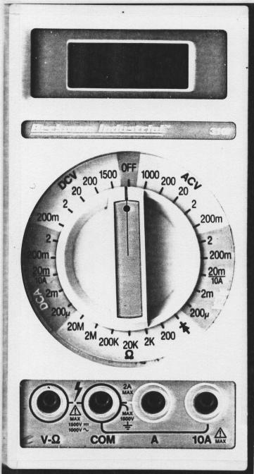
6 22 E7.6 BECKMAN 310 DIGITAL MULTIMETER The Beckman 310 Multimeter can be used to measure DC and AC voltage, DC and AC current, and resistance. DC Voltage: To measure DC voltage connect the positive lead to the leftmost input labelled V and the other lead to the COM input. The DCV section of the central dial has five divisions (200m, 2, 20, 200 and 1500) marked with the MAXIMUM voltage that can be handled without overloading the meter circuitry. The smaller numbered divisions have greater accuracy. To avoid overloading the circuitry, first turn the dial to the 1500 scale. If the voltage (or the maximum voltage expected) is less than the next lower division s maximum (200 volts) you can safely rotate the dial counter-clockwise to the next division. You can repeat this procedure until you reach the division with greatest accuracy that does NOT overload the meter. If you reach the 200m scale the meter will read in millivolts. AC Voltage: To measure AC voltage connect the leads to the V and COM inputs. Turn the dial clockwise into the ACV range. Follow a similar procedure to that described under DC Voltage to avoid overloading the meter. DC Current: To measure DC current connect the positive circuit lead to the 10A input and the other lead into the COM input. Turn the dial to the 20m/10A position in the DCA range. The meter will now read in amps to a maximum of 10 amps. If the meter reads less than 2 amps and you are sure that the maximum expected current will ALWAYS be under 2 amps, then you can safely obtain a more accurate reading by turning the meter off and reconnecting the positive lead to the A input. (NOTE: you will blow a fuse if the current ever exceeds 2 amps.) The dial can now be turned to the 2 division in the DCA range. If the current is less than 0.2 amps, turn the dial to the 200m division for greater accuracy. The meter will now read in milliamps. You can continue to switch to finer divisions providing you do NOT exceed the MAXIMUM current indicated on the dial. The finest division reads in microamps to a maximum of 200 microamps. AC Current: Follow the same procedure as described under DC Current except that the dial is rotated into the ACA range. Resistance: To measure the resistance of a circuit element, first disconnect the electrical connections of that element from any other part of the circuit. Then connect a lead from one end of the element into the ohm ( ) input and a lead from the other end into the COM input. Rotate the dial into the ohm ( ) range starting with the coarse scale (20M) where resistance will be read in Mega-ohms (M ). You can rotate the dial to finer divisions providing the resistance does NOT exceed the MAXIMUM RESISTANCE indicated. If you use the 200K, 20K or 2K divisions the resistance will read in kilo-ohms (k ). If you use the 200 division, the resistance will read in ohms ( ) to a maximum of only 200 ohms.
7 23 E7.7
8 24 E7.8 Resistors are marked with coloured bands which are interpreted according to a colour code: 0 = Black 5 = Green 1 = Brown 6 = Blue 2 = Red 7 = Violet 3 = Orange 8 = Grey 4 = Yellow 9 = White Gold: 5% Silver: 10% The first two bands give the two significant figures of the resistor value in terms of the code, the third band gives the power of 10 that multiplies the first two figures. The fourth band gives the tolerance (accuracy). If there is no fourth band, the tolerance is 20%. e.g. Yellow-Violet-Red-Silver = %
9 25 E7 OHM'S LAW AND RESISTANCE NETWORKS DATA & RESULTS VOLTAGE AND CURRENT DATA FOR RESISTOR R 3 Voltage, V Current, I Voltage, V Current, I ( V) ( A) ( V) ( A) RESISTANCE VALUES FOR EXPERIMENT E7 Graphical ( ) Measured ( ) Calculated ( ) R 1 R 2 R 3 R SERIES R PARALLEL
10 26 This page intentionally left blank.
11 27 Voltage versus Current for Resistor R 3 to determine relationship and resistance Voltage, V (V) Current, I (A)
OHM'S LAW AND RESISTANCE NETWORKS OBJECT
 17 E7 E7.1 OHM'S LAW AND RESISTANCE NETWORKS OBJECT The objects of this experiment are to determine the voltage-current relationship for a resistor and to verify the series and parallel resistance formulae.
Lab 3 DC CIRCUITS AND OHM'S LAW
 43 Name Date Partners Lab 3 DC CIRCUITS AND OHM'S LAW AMPS + - VOLTS OBJECTIVES To learn to apply the concept of potential difference (voltage) to explain the action of a battery in a circuit. To understand
DC CIRCUITS AND OHM'S LAW
 July 15, 2008 DC Circuits and Ohm s Law 1 Name Date Partners DC CIRCUITS AND OHM'S LAW AMPS - VOLTS OBJECTIVES OVERVIEW To learn to apply the concept of potential difference (voltage) to explain the action
II. Experimental Procedure
 Ph 122 July 27, 2006 Ohm's Law http://www.physics.sfsu.edu/~manuals/ph122/ I. Theory In this lab we will make detailed measurements on one resistor to see if it obeys Ohm's law. We will also verify the
Current, resistance, and Ohm s law
 Current, resistance, and Ohm s law Apparatus DC voltage source set of alligator clips 2 pairs of red and black banana clips 3 round bulb 2 bulb sockets 2 battery holders or 1 two-battery holder 2 1.5V
Ohm s Law and Electrical Circuits
 Ohm s Law and Electrical Circuits INTRODUCTION In this experiment, you will measure the current-voltage characteristics of a resistor and check to see if the resistor satisfies Ohm s law. In the process
Experiment 2. Ohm s Law. Become familiar with the use of a digital voltmeter and a digital ammeter to measure DC voltage and current.
 Experiment 2 Ohm s Law 2.1 Objectives Become familiar with the use of a digital voltmeter and a digital ammeter to measure DC voltage and current. Construct a circuit using resistors, wires and a breadboard
RESISTANCE & OHM S LAW (PART I
 RESISTANCE & OHM S LAW (PART I and II) Objectives: To understand the relationship between potential and current in a resistor and to verify Ohm s Law. To understand the relationship between potential and
EK307 Introduction to the Lab
 EK307 Introduction to the Lab Learning to Use the Test Equipment Laboratory Goal: Become familiar with the test equipment in the electronics laboratory (PHO105). Learning Objectives: Voltage source and
Experiment 3. Ohm s Law. Become familiar with the use of a digital voltmeter and a digital ammeter to measure DC voltage and current.
 Experiment 3 Ohm s Law 3.1 Objectives Become familiar with the use of a digital voltmeter and a digital ammeter to measure DC voltage and current. Construct a circuit using resistors, wires and a breadboard
Lab 4 OHM S LAW AND KIRCHHOFF S CIRCUIT RULES
 57 Name Date Partners Lab 4 OHM S LAW AND KIRCHHOFF S CIRCUIT RULES AMPS - VOLTS OBJECTIVES To learn to apply the concept of potential difference (voltage) to explain the action of a battery in a circuit.
DC Circuits and Ohm s Law
 DC Circuits and Ohm s Law INTRODUCTION During the nineteenth century so many advances were made in understanding the electrical nature of matter that it has been called the age of electricity. One such
1-1. Kirchoff s Laws A. Construct the circuit shown below. R 1 =1 kω. = 2.7 kω R 3 R 2 5 V
 Physics 310 Lab 1: DC Circuits Equipment: Digital Multimeter, 5V Supply, Breadboard, two 1 kω, 2.7 kω, 5.1 kω, 10 kω, two, Decade Resistor Box, potentiometer, 10 kω Thermistor, Multimeter Owner s Manual
DC Circuits and Ohm s Law
 DC Circuits and Ohm s Law INTRODUCTION During the nineteenth century so many advances were made in understanding the electrical nature of matter that it has been called the age of electricity. One such
Ohm's Law and DC Circuits
 Physics Lab II Ohm s Law Name: Partner: Partner: Partner: Ohm's Law and DC Circuits EQUIPMENT NEEDED: Circuits Experiment Board Two Dcell Batteries Wire leads Multimeter 100, 330, 560, 1k, 10k, 100k, 220k
V (in volts) = voltage applied to the circuit, I (in amperes) = current flowing in the circuit, R (in ohms) = resistance of the circuit.
 = voltage applied to the circuit, I (in amperes) = current flowing in the circuit, R (in ohms) = resistance of the circuit.") OHM S LW OBJECTIES: PRT : 1) Become familiar with the use of ammeters and voltmeters to measure DC voltage and current. 2) Learn to use wires and a breadboard to build circuits from a circuit diagram.
OHM S LW OBJECTIES: PRT : 1) Become familiar with the use of ammeters and voltmeters to measure DC voltage and current. 2) Learn to use wires and a breadboard to build circuits from a circuit diagram.
Electrical Measurements
 Electrical Measurements INTRODUCTION In this section, electrical measurements will be discussed. This will be done by using simple experiments that introduce a DC power supply, a multimeter, and a simplified
General Lab Notebook instructions (from syllabus)
") Physics 310 Lab 1: DC Circuits Equipment: Digital Multimeter, 5V Supply, Breadboard, two 1 k, 2.7 k, 5.1 k, 10 k, two Decade Resistor Box, potentiometer, 10 k Thermistor, Multimeter Owner s Manual General
Physics 310 Lab 1: DC Circuits Equipment: Digital Multimeter, 5V Supply, Breadboard, two 1 k, 2.7 k, 5.1 k, 10 k, two Decade Resistor Box, potentiometer, 10 k Thermistor, Multimeter Owner s Manual General
DC Circuits, Ohm's Law and Multimeters Physics 246
 DC Circuits, Ohm's Law and Multimeters Physics 246 Theory: In this lab we will learn the use of multimeters, verify Ohm s law, and study series and parallel combinations of resistors and capacitors. For
ENGR 120 LAB #2 Electronic Tools and Ohm s Law
 ENGR 120 LAB #2 Electronic Tools and Ohm s Law Objectives Understand how to use a digital multi-meter, power supply and proto board and apply that knowledge to constructing circuits to demonstrate ohm
PHYS 1402 General Physics II Experiment 5: Ohm s Law
 PHYS 1402 General Physics II Experiment 5: Ohm s Law Student Name Objective: To investigate the relationship between current and resistance for ordinary conductors known as ohmic conductors. Theory: For
Lab 1: Basic Lab Equipment and Measurements
 Abstract: Lab 1: Basic Lab Equipment and Measurements This lab exercise introduces the basic measurement instruments that will be used throughout the course. These instruments include multimeters, oscilloscopes,
EET140/3 ELECTRIC CIRCUIT I
 SCHOOL OF ELECTRICAL SYSTEM ENGINEERING UNIVERSITI MALAYSIA PERLIS EET140/3 ELECTRIC CIRCUIT I MODULE 1 PART I: INTRODUCTION TO BASIC LABORATORY EQUIPMENT PART II: OHM S LAW PART III: SERIES PARALEL CIRCUIT
HANDS-ON ACTIVITY 4 BUILDING SERIES AND PARALLEL CIRCUITS BACKGROUND WIRING DIRECTIONS
 ACTIVITY 4 BUILDING SERIES AND PARALLEL CIRCUITS BACKGROUND Make sure you read the background in Activity 3 before doing this activity. WIRING DIRECTIONS Materials per group of two: one or two D-cells
DC Electric Circuits: Resistance and Ohm s Law
 DC Electric Circuits: Resistance and Ohm s Law Goals and Introduction Our society is very reliant on electric phenomena, perhaps most so on the utilization of electric circuits. For much of our world to
Simple Circuits Experiment
 Physics 8.02T 1 Fall 2001 Simple Circuits Experiment Introduction Our world is filled with devices that contain electrical circuits in which various voltage sources cause currents to flow. We use radios,
Engineering Laboratory Exercises (Electric Circuits Module) Prepared by
 Prepared by") Engineering 1040 Laboratory Exercises (Electric Circuits Module) Prepared by Eric W. Gill FALL 2008 2 EXP 1040-EL1 VOLTAGE, CURRENT, RESISTANCE AND POWER PURPOSE To (i) investigate the relationship between
Engineering 1040 Laboratory Exercises (Electric Circuits Module) Prepared by Eric W. Gill FALL 2008 2 EXP 1040-EL1 VOLTAGE, CURRENT, RESISTANCE AND POWER PURPOSE To (i) investigate the relationship between
Multimeter Introduction
 Multimeter Introduction Abstract The general aim of this lab is to introduce you to the proper use of a digital multimeter with its associated uncertainties and to show how to propagate those uncertainties.
Pre-Lab for Batteries and Bulbs
 Pre-Lab for Batteries and Bulbs Complex circuits composed of resistors can be simplified by using the concept of equivalent resistors. For example if resistors R 1, R 2, and R 3 are connected in series,
Lab 4 Ohm s Law and Resistors
 ` Lab 4 Ohm s Law and Resistors What You Need To Know: The Physics One of the things that students have a difficult time with when they first learn about circuits is the electronics lingo. The lingo and
DC Circuits. Date: Introduction
 Group # Date: Names: DC Circuits Introduction In this experiment you will examine how to make simple DC measurements that involve current, voltage, and resistance. The current I through a resistor R with
Tutorial Using a multimeter
 Tutorial Using a multimeter The multimeter You might have already seen or worked with a multimeter. It is an electronic measuring device that combines several instruments such as the voltmeter (to measure
Introduction to the Laboratory
 Memorial University of Newfoundland Department of Physics and Physical Oceanography Physics 2055 Laboratory Introduction to the Laboratory The purpose of this lab is to introduce you to some of the equipment
Module 1, Lesson 2 Introduction to electricity. Student. 45 minutes
 Module 1, Lesson 2 Introduction to electricity 45 minutes Student Purpose of this lesson Explanations of fundamental quantities of electrical circuits, including voltage, current and resistance. Use a
Voltage Current and Resistance II
 Voltage Current and Resistance II Equipment: Capstone with 850 interface, analog DC voltmeter, analog DC ammeter, voltage sensor, RLC circuit board, 8 male to male banana leads 1 Purpose This is a continuation
EE 210: CIRCUITS AND DEVICES
 EE 210: CIRCUITS AND DEVICES LAB #3: VOLTAGE AND CURRENT MEASUREMENTS This lab features a tutorial on the instrumentation that you will be using throughout the semester. More specifically, you will see
Experiment 16: Series and Parallel Circuits
 Experiment 16: Series and Parallel Circuits Figure 16.1: Series Circuit Figure 16.2: Parallel Circuit 85 86 Experiment 16: Series and Parallel Circuits Figure 16.3: Combination Circuit EQUIPMENT Universal
Physics 1051 Laboratory #4 DC Circuits and Ohm s Law. DC Circuits and Ohm s Law
 DC Circuits and Ohm s Law Contents Part I: Objective Part II: Introduction Part III: Apparatus and Setup Part IV: Measurements Part V: Analysis Part VI: Summary and Conclusions Part I: Objective In this
MEASUREMENTS & INSTRUMENTATION ANALOG AND DIGITAL METERS
 MEASUREMENTS & INSTRUMENTATION ANALOG AND DIGITAL METERS ANALOG Metering devices Provides monotonous (continuous) movement. ELECTRICAL MEASURING INSTRUMENTS ANALOG METERS A d Arsonval galvanometer (Moving
Series and Parallel Resistors
 Lab 8. Series and Parallel Resistors Goals To understand the fundamental difference between resistors connected in series and in parallel. To calculate the voltages and currents in simple circuits involving
Pre-Laboratory Assignment
 Measurement of Electrical Resistance and Ohm's Law PreLaboratory Assignment Read carefully the entire description of the laboratory and answer the following questions based upon the material contained
Lab 11: Circuits. Figure 1: A hydroelectric dam system.
 Description Lab 11: Circuits In this lab, you will study voltage, current, and resistance. You will learn the basics of designing circuits and you will explore how to find the total resistance of a circuit
THE BREADBOARD; DC POWER SUPPLY; RESISTANCE OF METERS; NODE VOLTAGES AND EQUIVALENT RESISTANCE; THÉVENIN EQUIVALENT CIRCUIT
 THE BREADBOARD; DC POWER SUPPLY; RESISTANCE OF METERS; NODE VOLTAGES AND EQUIVALENT RESISTANCE; THÉVENIN EQUIVALENT CIRCUIT YOUR NAME GTA S SIGNATURE LAB MEETING TIME Objectives: To correctly operate the
Aim: To learn the resistor color codes and building a circuit on a BreadBoard. Equipment required: Resistances, millimeter, power supply
 Understanding the different components Aim: To learn the resistor color codes and building a circuit on a BreadBoard Equipment required: Resistances, millimeter, power supply Resistors are color coded
University of Jordan School of Engineering Electrical Engineering Department. EE 219 Electrical Circuits Lab
 University of Jordan School of Engineering Electrical Engineering Department EE 219 Electrical Circuits Lab EXPERIMENT 1 REPORT MEASUREMENT DEVICES Group # 1. 2. 3. 4. Student Name ID EXPERIMENT 1 MEASUREMENT
PHYSICS 221 LAB #6: CAPACITORS AND AC CIRCUITS
 Name: Partners: PHYSICS 221 LAB #6: CAPACITORS AND AC CIRCUITS The electricity produced for use in homes and industry is made by rotating coils of wire in a magnetic field, which results in alternating
Ohm's Law and the Measurement of Resistance
 Ohm's Law and the Measurement of Resistance I. INTRODUCTION An electric current flows through a conductor when a potential difference is placed across its ends. The potential difference is generally in
Experiment 1 Basic Resistive Circuit Parameters
 Experiment 1 Basic Resistive Circuit Parameters Report Due In-class on Wed., Mar. 14, 2018 Note: (1) The Prelab section must be completed prior to the lab period. (2) All submitted lab reports should have
University of Jordan School of Engineering Electrical Engineering Department. EE 204 Electrical Engineering Lab
 University of Jordan School of Engineering Electrical Engineering Department EE 204 Electrical Engineering Lab EXPERIMENT 1 MEASUREMENT DEVICES Prepared by: Prof. Mohammed Hawa EXPERIMENT 1 MEASUREMENT
ECE 53A: Fundamentals of Electrical Engineering I
 ECE 53A: Fundamentals of Electrical Engineering I Laboratory Assignment #1: Instrument Operation, Basic Resistor Measurements and Kirchhoff s Laws Fall 2007 General Guidelines: - Record data and observations
EGR 101 LABORATORY 1 APPLICATION OF ALGEBRA IN ENGINEERING Wright State University
 EGR 101 LABORATORY 1 APPLCATON OF ALGEBRA N ENGNEERNG Wright State University OBJECTVE: The objective of this laboratory is to illustrate applications of algebra (lines and quadratics) in engineering.
EE1020 Diodes and Resistors in Electrical Circuits Spring 2018
 PURPOSE The purpose of this project is for you to become familiar with some of the language, parts, and tools used in electrical engineering. You will also be introduced to some simple rule and laws. MATERIALS
electrical noise and interference, environmental changes, instrument resolution, or uncertainties in the measurement process itself.
 MUST 382 / EELE 491 Spring 2014 Basic Lab Equipment and Measurements Electrical laboratory work depends upon various devices to supply power to a circuit, to generate controlled input signals, and for
Lab #1 Help Document. This lab will be completed in room 335 CTB. You will need to partner up for this lab in groups of two.
 Lab #1 Help Document This help document will be structured as a walk-through of the lab. We will include instructions about how to write the report throughout this help document. This lab will be completed
Multimeter operating guidelines
 A multimeter, also called a volt-ohm meter or VOM, is a device that measures resistance, voltage and current in electronic circuits. Some also test diodes and continuity. Multimeters are small, lightweight
Electric Circuit Experiments
 Electric Circuit Experiments 1. Using the resistor on the 5-resistor block, vary the potential difference across it in approximately equal increments for eight different values (i.e. use one to eight D-
rheostat (about 100 ) multimeter
 multimeter") 0BOhm's Law and Resistivity (approx. 2 h) (8/6/15) 1BIntroduction In this lab you will investigate simple DC (direct or constant current) circuits using a DC power supply, a multimeter and wire resistors.
0BOhm's Law and Resistivity (approx. 2 h) (8/6/15) 1BIntroduction In this lab you will investigate simple DC (direct or constant current) circuits using a DC power supply, a multimeter and wire resistors.
Figure 1(a) shows a complicated circuit with five batteries and ten resistors all in a box. The
 shows a complicated circuit with five batteries and ten resistors all in a box. The") 1 Lab 1a Input and Output Impedance Fig. 1: (a) Complicated circuit. (b) Its Thévenin equivalent Figure 1(a) shows a complicated circuit with five batteries and ten resistors all in a box. The circuit
1 Lab 1a Input and Output Impedance Fig. 1: (a) Complicated circuit. (b) Its Thévenin equivalent Figure 1(a) shows a complicated circuit with five batteries and ten resistors all in a box. The circuit
EE283 Laboratory Exercise 1-Page 1
 EE283 Laboratory Exercise # Basic Circuit Concepts Objectives:. To become familiar with the DC Power Supply unit, analog and digital multi-meters, fixed and variable resistors, and the use of solderless
Exercise 3: Voltage in a Series Resistive Circuit
 DC Fundamentals Series Resistive Circuits Exercise 3: Voltage in a Series Resistive Circuit EXERCISE OBJECTIVE When you have completed this exercise, you will be able to determine the voltage in a series
Experiment 3 Ohm s Law
 Experiment 3 Ohm s Law The goals of Experiment 3 are: To identify resistors based upon their color code. To construct a two-resistor circuit using proper wiring techniques. To measure the DC voltages and
Pre-LAB 5 Assignment
 Name: Lab Partners: Date: Pre-LA 5 Assignment Fundamentals of Circuits III: Voltage & Ohm s Law (Due at the beginning of lab) Directions: Read over the Lab Fundamentals of Circuits III: Voltages :w & Ohm
Materials: resistors: (5) 1 kω, (4) 2 kω, 2.2 kω, 3 kω, 3.9 kω digital multimeter (DMM) power supply w/ leads breadboard, jumper wires
 1 kω, (4) 2 kω, 2.2 kω, 3 kω, 3.9 kω digital multimeter (DMM) power supply w/ leads breadboard, jumper wires") Lab 6: Electrical Engineering Technology References: 1. Resistor (electronic) color code: http://en.wikipedia.org/wiki/electronic_color_code 2. Resistor color code tutorial: http://www.michaels-electronics-lessons.com/resistor-color-code.html
Lab 6: Electrical Engineering Technology References: 1. Resistor (electronic) color code: http://en.wikipedia.org/wiki/electronic_color_code 2. Resistor color code tutorial: http://www.michaels-electronics-lessons.com/resistor-color-code.html
Oregon State University Lab Session #1 (Week 3)
") Oregon State University Lab Session #1 (Week 3) ENGR 201 Electrical Fundamentals I Equipment and Resistance Winter 2016 EXPERIMENTAL LAB #1 INTRO TO EQUIPMENT & OHM S LAW This set of laboratory experiments
Oregon State University Lab Session #1 (Week 3) ENGR 201 Electrical Fundamentals I Equipment and Resistance Winter 2016 EXPERIMENTAL LAB #1 INTRO TO EQUIPMENT & OHM S LAW This set of laboratory experiments
Introduction to Electronic Equipment
 Introduction to Electronic Equipment INTRODUCTION This semester you will be exploring electricity and magnetism. In order to make your time in here more instructive we ve designed this laboratory exercise
Guide to Using the Multimeter
 Guide to Using the Multimeter 33-01 This guide was produced by the Société de formation à distance des commissions scolaires du Québec. Production Coordinator : Development : Translation : Scientific Proofreading
Lab 1 - Intro to DC Circuits
 Objectives Pre-Lab Background Equipment List Procedure Equipment Familiarization Student PC Board DC Power Supply Digital Multimeter Power Supply Cont Decade Box Ohms Law and Power Dissipation Current
EET 150 Introduction to EET Lab Activity 1 Resistor Color Codes and Resistor Value Measurement
 Required Parts, Software and Equipment Parts 20 assorted 1/4 watt resistors 5% tolerance Equipment Required Solderless Experimenters' Board Digital Multimeter Optional Alligator clip leads hookup wire
DEPARTMENT OF ELECTRONIC ENGINEERING ELECTRONIC WORKSHOP # 03. Resistors
 MEHRAN UNIVERSITY OF ENGINEERING AND TECHNOLOGY, JAMSHORO DEPARTMENT OF ELECTRONIC ENGINEERING ELECTRONIC WORKSHOP # 03 Resistors Roll. No: Checked by: Date: Grade: Object: To become familiar with resistors,
Electronic Instrument Disadvantage of moving coil meter Low input impedance High loading error for low-voltage range voltmeter
 EIE 240 Electrical and Electronic Measurement Class 6, February 20, 2015 1 Electronic Instrument Disadvantage of moving coil meter Low input impedance High loading error for low-voltage range voltmeter
AME140 Lab #2 INTRODUCTION TO ELECTRONIC TEST EQUIPMENT AND BASIC ELECTRONICS MEASUREMENTS
 INTRODUCTION TO ELECTRONIC TEST EQUIPMENT AND BASIC ELECTRONICS MEASUREMENTS The purpose of this document is to guide students through a few simple activities to increase familiarity with basic electronics
Laboratory Project 1a: Power-Indicator LED's
 2240 Laboratory Project 1a: Power-Indicator LED's Abstract-You will construct and test two LED power-indicator circuits for your breadboard in preparation for building the Electromyogram circuit in Lab
Revision: Jan 29, E Main Suite D Pullman, WA (509) Voice and Fax
 Voice and Fax") Revision: Jan 29, 2011 215 E Main Suite D Pullman, WA 99163 (509) 334 6306 Voice and Fax Overview The purpose of this lab assignment is to provide users with an introduction to some of the equipment which
Revision: Jan 29, 2011 215 E Main Suite D Pullman, WA 99163 (509) 334 6306 Voice and Fax Overview The purpose of this lab assignment is to provide users with an introduction to some of the equipment which
Experiment 2 Electric Circuit Fundamentals
 Experiment 2 Electric Circuit Fundamentals Introduction This experiment has two parts. Each part will have to be carried out using the Multisim Electronics Workbench software. The experiment will then
Direct Current Circuits
 PC1143 Physics III Direct Current Circuits 1 Objectives Apply Kirchhoff s rules to several circuits, solve for the currents in the circuits and compare the theoretical values predicted by Kirchhoff s rule
Experiment 1: Circuits Experiment Board
 01205892C AC/DC Electronics Laboratory Experiment 1: Circuits Experiment Board EQUIPMENT NEEDED: AC/DC Electronics Lab Board: Wire Leads Dcell Battery Graph Paper Purpose The purpose of this lab is to
Electric Circuit I Lab Manual Session # 2
 Electric Circuit I Lab Manual Session # 2 Name: ----------- Group: -------------- 1 Breadboard and Wiring Objective: The objective of this experiment is to be familiar with breadboard and connection made
Laboratory Equipment Instruction Manual 2011
 University of Toronto Department of Electrical and Computer Engineering Instrumentation Laboratory GB341 Laboratory Equipment Instruction Manual 2011 Page 1. Wires and Cables A-2 2. Protoboard A-3 3. DC
Laboratory Project 1B: Electromyogram Circuit
 2240 Laboratory Project 1B: Electromyogram Circuit N. E. Cotter, D. Christensen, and K. Furse Electrical and Computer Engineering Department University of Utah Salt Lake City, UT 84112 Abstract-You will
Exercise MM About the Multimeter
 Exercise MM About the Multimeter Introduction Our world is filled with devices that contain electrical circuits in which various voltage sources cause currents to flow. Electrical currents generate heat,
Introduction to oscilloscope. and time dependent circuits
 Physics 9 Intro to oscilloscope, v.1.0 p. 1 NAME: SECTION DAY/TIME: TA: LAB PARTNER: Introduction to oscilloscope and time dependent circuits Introduction In this lab, you ll learn the basics of how to
Resistance and Ohm s law
 Resistance and Ohm s law Objectives Characterize materials as conductors or insulators based on their electrical properties. State and apply Ohm s law to calculate current, voltage or resistance in an
EXAMPLE. Use this jack for the red test lead when measuring. current from 0 to 200mA. Figure P-1
 Digital Multimeters ON / OFF power switch Continuity / Diode Test Function Resistance Function Ranges from 200Ω to 200MΩ Transistor Test Function DC Current Function Ranges from 2mA to 20A. AC Current
The University of Jordan Mechatronics Engineering Department Electronics Lab.( ) Experiment 1: Lab Equipment Familiarization
 Experiment 1: Lab Equipment Familiarization") The University of Jordan Mechatronics Engineering Department Electronics Lab.(0908322) Experiment 1: Lab Equipment Familiarization Objectives To be familiar with the main blocks of the oscilloscope and
The University of Jordan Mechatronics Engineering Department Electronics Lab.(0908322) Experiment 1: Lab Equipment Familiarization Objectives To be familiar with the main blocks of the oscilloscope and
AC/DC ELECTRONICS LABORATORY
 Includes Teacher's Notes and Typical Experiment Results Instruction Manual and Experiment Guide for the PASCO scientific Model EM-8656 012-05892A 1/96 AC/DC ELECTRONICS LABORATORY 1995 PASCO scientific
Notes on Experiment #3
 Notes on Experiment #3 This week you learn to measure voltage, current, and resistance with the digital multimeter (DMM) You must practice measuring each of these quantities (especially current) as much
I. Objectives Upon completion of this experiment, the student should be able to: Ohm s Law
 EENG-201 Experiment # 1 Series Circuit and Parallel Circuits I. Objectives Upon completion of this experiment, the student should be able to: 1. ead and use the resistor color code. 2. Use the digital
Resistance. Department of Physics & Astronomy Texas Christian University, Fort Worth, TX. April 23, 2013
 Resistance Department of Physics & Astronomy Texas Christian University, Fort Worth, TX April 23, 2013 1 Introduction Electrical resistance is a measure of how much an object opposes (or resists) the flow
PHY132 Summer 2010 Ohm s Law
 PHY132 Summer 2010 Ohm s Law Introduction: In this lab, we will examine the concepts of electrical resistance and resistivity. Text Reference Young & Freedman 25.2-3. Special equipment notes: 1. Note the
OHM S LAW. Ohm s Law The relationship between potential difference (V) across a resistor of resistance (R) and the current (I) passing through it is
 across a resistor of resistance (R) and the current (I) passing through it is") OHM S LAW Objectives: a. To find the unknown resistance of an ohmic resistor b. To investigate the series and parallel combination of resistors c. To investigate the non-ohmic resistors Apparatus Required:
OHM S LAW Objectives: a. To find the unknown resistance of an ohmic resistor b. To investigate the series and parallel combination of resistors c. To investigate the non-ohmic resistors Apparatus Required:
Episode 108: Resistance
 Episode 108: Resistance The idea of resistance should be familiar (although perhaps not secure) from pre-16 science course, so there is no point pretending that this is an entirely new concept. A better
(%) ex Blue-Black-Brown-Gold 600 Ω ± 5% ± 30 1
 ex Blue-Black-Brown-Gold 600 Ω ± 5% ± 30 1") ** Disclaimer: This Lab is not to be copied, duplicated, and/or distributed, in whole or in part, unless approval is received from the University of Colorado at Colorado Springs Physics Department AND
** Disclaimer: This Lab is not to be copied, duplicated, and/or distributed, in whole or in part, unless approval is received from the University of Colorado at Colorado Springs Physics Department AND
Name: Resistors and Basic Resistive Circuits. Objective: To gain experience with data acquisition proto-boards physical resistors. Table of Contents:
 Objective: To gain experience with data acquisition proto-boards physical resistors Table of Contents: Name: Resistors and Basic Resistive Circuits Pre-Lab Assignment 1 Background 2 National Instruments
Sept 13 Pre-lab due Sept 12; Lab memo due Sept 19 at the START of lab time, 1:10pm
 Sept 13 Pre-lab due Sept 12; Lab memo due Sept 19 at the START of lab time, 1:10pm EGR 220: Engineering Circuit Theory Lab 1: Introduction to Laboratory Equipment Pre-lab Read through the entire lab handout
Voltage, Current and Resistance
 Voltage, Current and Resistance Foundations in Engineering WV Curriculum, 2002 Foundations in Engineering Content Standards and Objectives 2436.8.3 Explain the relationship between current, voltage, and
Part 1: DC Concepts and Measurement
 EE 110 Introduction to Engineering & Laboratory Experience Saeid Rahimi, Ph.D. Lab 1 DC Concepts and Measurement: Ohm's Law, Voltage ad Current Introduction to Analog Discovery Scope Last week we introduced
Electrical Measurements
 Electrical Measurements. OBJECTIES: This experiment covers electrical measurements, including use of the volt-ohmmeter and oscilloscope. Concepts including Ohm's Law, Kirchoff's Current and oltage Laws,
Chapter 13. Electric Circuits
 Chapter 13 Electric Circuits Lower Potential Battery (EMF - E) - + Higher Potential Bulb (Resistor) Wires (No Change in Potential) EMF (Voltage Source) _ + Resistor Working Circuits For a circuit to work,
DC Circuits PHYS 501 Homework 2
 DC Circuits PHYS 501 Homework 2 NAME: (partner if any: ) In-class Laboratory. Worth 12 points. A "circuit" is a circular (completed) path from the red or "+" side of a voltage source through various "circuit
Practical 2.1 BASIC ELECTRICAL MEASUREMENTS AND DATA PROCESSING
 Practical 2.1 BASIC ELECTRICAL MEASUREMENTS AND DATA PROCESSING September 6, 2017 1 Introduction To measure electrical quantities one uses electrical measuring instruments. There are three main quantities