Power Supply Board. by Classic Valve Design for the Dynaco Mark-III with failsafe bias and balance
|
|
|
- Derick Black
- 6 years ago
- Views:
Transcription

1 Power Supply Board by Classic Valve Design for the Dynaco Mark-III with failsafe bias and balance

2 Classic Valve Design assumes no responsibility for circuit or user damage from the use or misuse of these boards or any other product. We simply provide these on an AS-IS basis with workmanship quality as the only thing guaranteed at this time. This product is designed for and use around LETHAL VOLTAGES. We assume the user has a reasonably competent grasp of line operated electronics at the time of sale. * Dynaco is a registered trademark of Panor Corporation * * Board design is Classic Valve Design *
3 This power supply board allows you the opportunity to add a bias balance control to your Dynaco Mark 3, making output tube biasing a breeze and frees you from the need to buy tubes in matched pairs. Notice we have used the term failsafe bias, this is referring to the way the bias and balance pots are wired to deliver the required bias voltages. On the original Dynaco circuit, if the bias pot wiper lifts (the most common failure mode of a potentiometer), the output tubes lose bias, go into full conduction and are often destroyed (sometimes taking the output and/or power transformers with them). In this power supply, if any potentiometer wiper lifts, the output tubes will receive full negative bias voltage to their grids and simply cut off.
4
5 Parts List Capacitors: C1, C2: 82uF, 350V or 400V for 5U4/5AR4/GZ34 rectifier. 33uF, 350V or 400V for 5R4 rectifier. (See text) C3 - C8: 82uF, 350V or 400V. C9: 22n, 400V film type. C10, C11: 47uF, 100V Electrolytic. C12: 220n, 250V film type. Resistors: R1 - R8: 220K, 1 watt R9: 47K, 2 watt R10: 6.8K, 2 watt R11: 2.2K, ½ watt for KT88 (stock MK-III). 4.7K, ½ watt for EL34. R12 - R15: 10K, ½ watt. R16: 150K, ½ watt. RV1: 10K, ½ watt trimmer (or use original bias pot). RV2: 100K, ½ watt trimmer. Semiconductors: D1: 1N4007 Misc: CN1: 4-position terminal block, 5mm or 5.08mm pin spacing (or 2 x 2-position) CN2: 2-position terminal block, 5mm or 5.08mm pin spacing CN3: 3-position terminal block, 5mm or 5.08mm pin spacing Mounting hardware.
6 Circuit Notes A safety note about the capacitors: The exposed tops of C2, C4, C6, C8, C10 are HOT at ½ the rectified and filtered high voltage power supply voltage and should not be touched. The application of circle stickers found in stationary stores can be used to insulate these capacitor tops. Likewise, because of the -V bias supply, the exposed tops of bias capacitors C11 and C12 are at full negative bias voltage (up to -80V). Again application of circle stickers found in stationary stores can be used to insulate these capacitor tops. Please take care to make sure the capacitor's polarity is respected as outlined on the PCB and as per above schematic reversed polarized electrolytics have a tendency to EXPLODE, spewing hot electrolyte all over the place! C1 and C2 are the capacitors that the rectifier sees. The GZ34/5AR4 and the 5U4 variants will have no problem with 82uF, because the capacitor values are halved as they are stacked to increase voltage handling. So 2 x 82uF at 350V becomes 41uF at 700V in this circuit. The 5R4 variants aren't very happy with much above 15uF (though I haven't cooked one with 22uF in practise... yet). So 2 x 33uF will equal 16.5uF. Why haven't we stated 100uF like other popular aftermarket power supply boards? Size! There's a lot of stuff to fit on this board and the electrolytics in the high voltage section can be no more than 20mm in diameter by 25mm high. 100uF high voltage caps are out there (Nichicon is one that comes to mind) that fit that bill, but are not usually stocked by suppliers that sell to DIY'ers. The largest stocked in our search was 82uF, so we ran with that. Pads for a lead spacing of 7.5mm or 10mm (including snap-in types) are provided. By frequent request of our clients, here are some sample part numbers that will fit this unit. Since our commercial account is with Digikey, we will supply these numbers. This is in NO WAY a recommendation of one supplier over another. Parts not mentioned are easily fit and aren't too size specific.
7 Capacitors: C1, C2: 82uF, 350V or 400V. Digikey ND or P13557-ND. 33uF, 350V or 400V for 5R4. Digikey ND, ND, P13562-ND, P13552-ND or P13544-ND. C3 - C8: 82uF, 350V or 400V. Digikey ND or P13557-ND. (above types chosen for size, lead spacing and operation of 10,000 hours at 105ºC) C9: 22n, 400V film type. Digikey ND. C10, C11: 47uF, 100V Electrolytic. Digikey ND. C12: 220n, 250V film type. Digikey P14656-ND. Resistors: RV1: 10K, ½ watt trimmer. Bourns 3299W series. Digikey 3299W-103LF-ND. RV2: 100K, ½ watt trimmer. Bourns 3299W series. Digikey 3299W-104LF-ND.
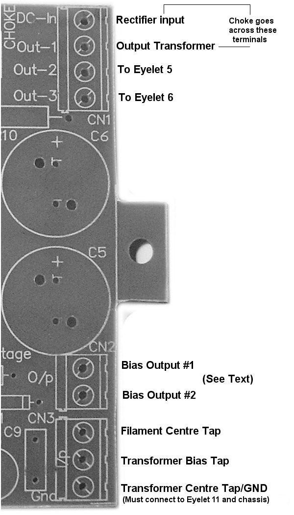
8 Hooking Up to the Circuitry Once the board is installed, you can begin hooking up the wiring from the top via the easy to use connectors. The output from the GZ34/5AR4 rectifier goes to the DC-in on CN1. The choke goes beteen DC-IN and OUT-1 on CN1. Attach the bias tap to the centre connection of CN3. Attach the power transformer's HV centre tap to the Gnd on CN3 and also run a wire from the second Gnd hole to the chassis star ground. If you (or someone else) have modified your MK-III to use a floating or other isolated ground system, attach the power transformer's HV centre tap to the Gnd and ground to your circuit as per your modifications. Attach the transformer filament centre tap to the first connection on CN3. Connect the centre tap of the output transformer to the Out-1 on CN1. Connect wire from eyelet #5 on the driver board to Out-2 on CN1. Connect wire from eyelet #6 on the driver board to Out-3 on CN1. Finally, connect either bias outputs from CN2 to eyelet #2 on the driver board, if you are using the original Dynaco driver. See the next section on conversion to balanced.
9
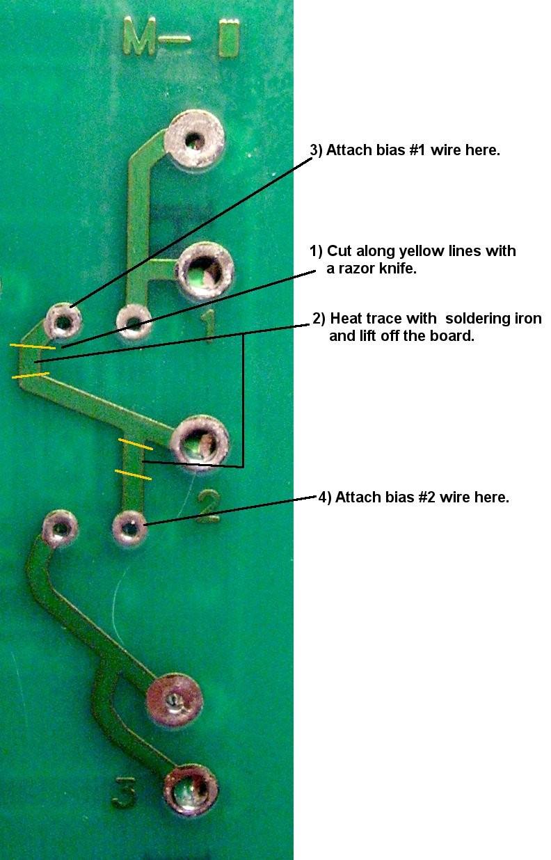
10 Converting the MK-III for Bias Balance Control This procedure is in two steps, changing the KT88 cathode circuitry and modifying the driver board (this step isn't necessary if you are using a driver with split bias connections). Step 1 Modifying the KT88 Cathodes: In order to monitor the bias in each KT88, we need to have a resistor on each KT88 cathode. We need to remove the existing 11.2 ohm resistor and the bridge between the two output tubes. We will use 10 ohm resistors on each cathode. Locate the 11.2 ohm resistor near one KT88 output tube socket. Remove it and replace it with one of the 10 ohm resistors. Locate the wire that goes between the two output tubes. Remove it. Solder another 10 ohm resistor the remaining KT88 pin 8 to chassis lug on the mounting rings. If you (or someone else) have modified your MK-III to use a floating or other isolated ground system, tie the ground side of the 10 ohm resistors to a terminal strip and run a wire to the ground terminal on the power supply board. Step 2 Modifying the Driver PCB: Simplest to show this as a picture on the next page:
11
12 First Power Up and Biasing Before first power up, remove your GZ34/5AR4 rectifier from the circuit. We want to test first that there is negative bias where there should be before applying B+ to the KT88 tubes. Connect a voltmeter on a setting to handle up to -80VDC to any left channel KT88 grid (pin 5) and electrical ground. Set RV1 and RV2 to midway. Turn on your MK-III. A negative voltage should register immediately, as it's a SS rectified circuit. If it does not, go through your component mounting and wiring thoroughly! Adjust RV2 for MAXIMUM negative voltage reading. Turn off your MK-III and replace the pulled rectifier tube. You are now ready for live biasing. Biasing and Balancing 1)Connect a voltmeter on a setting to handle up to 2VDC across either KT88 cathode 10 ohm resistor. 2)Turn on your MK-III. 3)As your MK-III warms up, you will see the voltage come up. If this cathode voltage creeps above 800mV (0.8V or 80mA for that tube) at this time, immediately turn off your MK-III and repeat First Power Up to look for the problem. If none is found, your tube grids may be on their way out (unable to restrict current flow enough). 4)After about three minutes warm up time, adjust RV2 for a bias reading of 700mV. This corresponds to 70mA current through that tube. 5)Now remove the negative voltmeter lead from electrical ground side of the 10 ohm resistor and place it on the cathode of the other KT88 (Pin 8). 6)Adjust RV1 for a reading of 0VDC (anything within 10mV (0.01V) is just fine). 7) Repeat steps 4-6. Congratulations! Your MK-III is now ready for service! :-)
13 Documentation written by Gregg van der Sluys, Classic Valve Design
Classic Valve Design
 DynaMull Driver Board for the Dynaco ST-70 Classic Valve Design Classic Valve Design assumes no responsibility for circuit or user damage from the use or misuse of these boards or any other product. We
DynaMutt Driver Board for the Dynaco ST-70
 DynaMutt Driver Board for the Dynaco ST-70 Octal Version Design by: Classic Valve Design Classic Valve Design assumes no responsibility for circuit or user damage from the use or misuse of these boards
Single Tube Line Stage. Classic Valve Design for the Dynaco PAS2, PAS3, PAS3X. Classic Valve Design
 Single Tube Line Stage by Classic Valve Design for the Dynaco PAS2, PAS3, PAS3X Classic Valve Design Classic Valve Design assumes no responsibility for circuit or user damage from the use or misuse of
Classic Valve Design
 7C Phono Stage for the Dynaco PAS2, PAS3, PAS3X Classic Valve Design Classic Valve Design assumes no responsibility for circuit or user damage from the use or misuse of these boards or any other product.
Classic Valve Design
 PAS Purist Line Amplifier Designed by Norman Koren (aka PAS-K Line) for the Dynaco PAS2, PAS3, PAS3X Classic Valve Design Classic Valve Design assumes no responsibility for circuit or user damage from
Mapletree Audio Design SR70A Special Red Driver Module for Dynaco ST-70
 Mapletree Audio Design S70A Special ed Driver Module for Dynaco ST-70 Installation instructions ev. Jan. 9/ The Special ed S70A driver module is a drop in replacement for the original driver board of the
Circuit and wiring connections as follows:
 Fault Indication via TTL compatible open collector output (can be used for additional protection circuitry or for our upcoming electronic choke PSU PCB) multiple mounting holes for easy mounting Can be
D. Gillespie Designs. SCA-35 Capacitor Board. Installation Manual. D. Gillespie Designs with EFB TM
 D. Gillespie Designs SCA-5 Capacitor Board with EFB TM Installation Manual D. Gillespie Designs www.tronola.com Thank you for choosing our SCA-5 Capacitor Board with *EFB. We feel it is the single most
DIY Tube Stereo 70 Board - TubeZone Assembled -Instructions - Page 1
 DIY Tube Stereo 70 Board - TubeZone Assembled -Instructions - Page 1 Board and portions of manual, (c) 2006 Shannon Parks & DIYtube.com. Version specific instructions (c) 2006 Ned Carlson and Tubezone.net
INSTRUCTIONS FOR ASSEMBLY AND OPERATION
 diytube stereo 0 driver board INSTRUCTIONS FOR ASSEMBLY AND OPERATION Price $0.00 Important Note: The phase is swapped on the diytube ST0 from the orginal design. Be sure to hook up the drive lines (at
Manual Version July 2007
 Manual Version 1.2 - July 2007 Page 1 Table of Contents Section1: M3 Phono Board Build...3 Phono Board Parts List...3 Preparation...4 Fitting the Valve Bases...6 Installing the Resistors...7 Starting the
WHISTLE ROCK AUDIO ML12 PSU KIT/PCB
 WHISTLE ROCK AUDIO ML12 PSU KIT/PCB TABLE OF CONTENTS 1. INTRODUCTION Page 3 2. BILL OF MATERIAL Page 4 3. ALTERNATE RESISTOR VALUES Page 5 4. ASSEMBLY GUIDE Page 6 to 11 5. CONNECTIONS Page 12 6. SETUP
You Just Brought an Old Radio Home: Now What Do You Do?
 You Just Brought an Old Radio Home: Now What Do You Do? Raymond Cady goldenageradiorestoration.com Whether you are just beginning to collect antique radios or you have been at it for a number of years,
PM124 Installation Instructions. See important note about revisions of this board on the last page.
 Marchand Electronics Inc. PO Box 473, Webster, NY 14580 Tel:(716) 872-0980 Fax:(716) 872-1960 info@marchandelec.com http://www.marchandelec.com (c)1997 Marchand Electronics Inc. PM124 Installation Instructions
TS500 Assembly guide. Soldering. TS500 Assembly guide Main PCB 1. Diodes. Document revision 1.2 Last modification : 17/12/16
 TS500 Assembly guide Safety warning The kits are main powered and use potentially lethal voltages. Under no circumstance should someone undertake the realisation of a kit unless he has full knowledge about
PM24 Installation Instructions
 Marchand Electronics Inc. PO Box 473, Webster, NY 14580 Tel:(716) 872-0980 Fax:(716) 872-1960 info@marchandelec.com http://www.marchandelec.com (c)1997 Marchand Electronics Inc. PM24 Installation Instructions
Starving Student II. Starving Student II. SS2 guide. Written By: 6L guides.diyaudio.com/ Page 1 of 24
 SS2 guide Written By: 6L6 2019 guides.diyaudio.com/ Page 1 of 24 INTRODUCTION This is a build guide for the hybrid headphone/pre-amplifier. You can buy a kit at the SSII product listing on the diyaudio
Tweed Champ 5F1 (assembling the board)
") Tweed Champ 5F1 (assembling the board) The Beginning of Great Tone - In 1958, the Fender Champ with it's 8 speaker and 5 watts of power became the mother of great tone. By combining the new 12AX7 with
Tweed Champ 5F1 (assembling the board) The Beginning of Great Tone - In 1958, the Fender Champ with it's 8 speaker and 5 watts of power became the mother of great tone. By combining the new 12AX7 with
Simple EL84 Basic layout. DIY Paradise 13 June 2003
 Simple EL84 Basic layout DIY Paradise 13 June 2003 EL84 doesn t sing without feedback. EL84 has no bass. These are comments I gleamed off the World Wide Web from various places. The truth is, if the circuit
Switcher Assembly guide. Switcher Assembly guide 1. Soldering. 2. Switcher3 vs Switcher2. 3. PCB split.
 Safety warning The kits are main powered and use potentially lethal voltages. Under no circumstance should someone undertake the realisation of a kit unless he has full knowledge about safely handling
Jason Stull. Physics 498 (Physics of Music) Valve Junior Modification 5/13/2010
 Valve Junior Modification 5/13/2010") Jason Stull Physics 498 (Physics of Music) Valve Junior Modification 5/13/2010 1 Introduction My original idea for a class project was to build a tube guitar amplifier. I have wanted a tube amp for some
Jason Stull Physics 498 (Physics of Music) Valve Junior Modification 5/13/2010 1 Introduction My original idea for a class project was to build a tube guitar amplifier. I have wanted a tube amp for some
Project 747 VERSION 1.3 USER MANUAL February 22nd 2018
 VERSION 1.3 USER MANUAL February 22nd 2018 WWW.GARAGE1217.COM WARNING: Project requires knowledge of AC electrical systems, repair of said systems and restoration of said systems. If proper safety measures
LA502 Assembly guide Main PCB Resistors - (2)
") LA502 Assembly guide Safety warning The kits are main powered and use potentially lethal voltages. Under no circumstance should someone undertake the realisation of a kit unless he has full knowledge about
LA502 Assembly guide Safety warning The kits are main powered and use potentially lethal voltages. Under no circumstance should someone undertake the realisation of a kit unless he has full knowledge about
Wiring the 1176LN Clone
 Back to Main 1176 Page 15 October 2004 modified 9 January 2005 revised 31 January 2006 Wiring the 1176LN Clone Keeping the Hum to a Minimum There's a feeling of satisfaction you get when you finish stuffing
STEP 0 Prepare the Materials.
 How to Build a Germanium Fuzz Guitar Effect. This document will guide you to build and test your Germanium Fuzz guitar pedal. With all the materials on hand, it takes around 2-4 hours to build it. Try
Dynaco MK3 Electrolytic Cap Upgrade Assembly, Installation, and Adjustment Manual
 Page 1 PC-M3U Rev 1 I. Introduction Thanks for your purchase of our Mark 3 Quad Electrolytic Capacitor Replacement Board PC-M3U. It has been designed to replace the original Dynaco Quad (4 section) Aluminum
DIODE / TRANSISTOR TESTER KIT
 DIODE / TRANSISTOR TESTER KIT MODEL DT-100K Assembly and Instruction Manual Elenco Electronics, Inc. Copyright 1988 Elenco Electronics, Inc. Revised 2002 REV-K 753110 DT-100 PARTS LIST If you are a student,
Dynaco ST-70 Input Board
 A u dio L ab s Sheldon Stokes 11811 Island Cove Dr. Fort Wayne, IN 46845 stokes@spinn.net http://www.quadesl.com Dynaco ST-70 Input Board 1 Introduction This board is a drop-in replacement for the original
Grounded Grid Plus Vacuum Tube Preamplifier User Manual. Analog Metric
 Grounded Grid Plus Vacuum Tube Preamplifier User Manual Analog Metric Page 2 INTRODUCTION This Grounded Grid Plus preamplifier provides enhanced performance out of the original Grounded Grid design. This
DIODE / TRANSISTOR TESTER KIT
 DIODE / TRANSISTOR TESTER KIT MODEL DT-100K 99 Washington Street Melrose, MA 02176 Phone 781-665-1400 Toll Free 1-800-517-8431 Visit us at www.testequipmentdepot.com Assembly and Instruction Manual Elenco
Assembly and Installation Instructions for White Oak Audio Design TM-1001 LED board
 Thank you for purchasing White Oak Audio Design s TM-1001 Upgrade LED Light Board. White Oak Audio Design products are meticulously engineered and tested to ensure a direct drop in fit with your tuner.
Troubleshooting Tutorial Page 1 Tech Note 4
 Page 1 Tech Note 4 Tools Required: RCA shorting plugs (Fabricate using Radio Shack # 274-339) Digital Voltmeter Soldering Iron & Associated items Screw drivers, Pliers (including needle nose), wire cutters
1.1 Original Amplifier Professional construction well made. No markings. Based on R&H Feb Watt Amplifier.
 4/03/2018 Australian 5W Combo Page 1 of 6 1. Summary Combo 5W Valve Amplifier and 8 Rola speaker. Unknown maker., Dec 2017. 1.1 Original Amplifier Professional construction well made. No markings. Based
A 75-Watt Transmitter for 3 Bands Simplified Shielding and Filtering for TVI BY DONALD H. MIX, W1TS ARRL Handbook 1953 and QST, October 1951
 A 75-Watt Transmitter for 3 Bands Simplified Shielding and Filtering for TVI BY DONALD H. MIX, W1TS ARRL Handbook 1953 and QST, October 1951 The transmitter shown in the photographs is a 3-stage 75-watt
SCA-35 System Capacitor Module Assembly & Instruction Manual
 SCA-35 System Capacitor Module Assembly & Instruction Manual I. Introduction Thank you for your purchase of our SCA35-CAP System Capacitor Module. It has been designed to replace both the power supply
IPR LA-3 KIT last update 15 march 06
 IPR LA-3 KIT last update 15 march 06 PART-2: Audio Circuitry CIRCUIT BOARD LAYOUT: Power and Ground Distribution Now that your power supply is functional, it s time to think about how that power will be
Instructions for Building the Pulsed Width Modulation Circuit. MC-12 (DC Motor Controller or PWM) From Electronic Light Inc. (revised kit 10/03/08)
 From Electronic Light Inc. (revised kit 10/03/08)") Instructions for Building the Pulsed Width Modulation Circuit MC-12 (DC Motor Controller or PWM) From Electronic Light Inc. (revised kit 10/03/08) Congratulations on your purchase of the MC-12 DC Motor
Instructions for Building the Pulsed Width Modulation Circuit MC-12 (DC Motor Controller or PWM) From Electronic Light Inc. (revised kit 10/03/08) Congratulations on your purchase of the MC-12 DC Motor
Balanced Modulator. Model 9748 Assembly and Using Manual PAiA Corporation
 Balanced Modulator Model 9748 Assembly and Using Manual This second-generation 9700-series processing element for modular sound synthesizers is designed to provide great sound and excellent value. Audio
Modifying a USB sound fob to act as a repeater interface for app_rpt
 Modifying a USB sound fob to act as a repeater interface for app_rpt This document explains how to modify a USB sound fob to work as a repeater interface for app_rpt. The following materials and tools
Construction notes for the symmetrical 400 watt amplifier
 Construction notes for the symmetrical 400 watt amplifier Introduction The symmetrical amplifier is an update of one of my designs, which appeared in the Australian electronics magazine Silicon Chip in
Mini Block Ultra Linear Class A Push-Pull Valve Power Amplifier
 Mini Block Ultra Linear Class A Push-Pull Valve Power Amplifier Precaution: This project uses potentially lethal voltages and should not be undertaken by anyone who is not familiar with working with such
Modifying The Heath HA-14 For 6 Meters Greg Chartrand - W7MY 4/22/07
 Introduction The Heathkit HA-14 was one of the few electron tube linear amplifiers intended for mobile use but few were purchased with the 12 volt mobile power supply. Most hams bought the HA-14 for base
Brief Installation Procedure: 1. Check the Parts 2. assembly each channel in brief and make sure the assembly is correct. 3. assembly the chassis in
 Brief Installation Procedure: 1. Check the Parts 2. assembly each channel in brief and make sure the assembly is correct. 3. assembly the chassis in brief, and make sure no small parts missed. 4. fixed
Build Your Own Clone Mouse Kit Instructions
 Build Your Own Clone Mouse Kit Instructions Warranty: BYOC, Inc. guarantees that your kit will be complete and that all parts and components will arrive as described, functioning and free of defect. Soldering,
Build Your Own Clone Crown Jewel Kit Instructions
 Build Your Own Clone Crown Jewel Kit Instructions Warranty: BYOC, Inc. guarantees that your kit will be complete and that all parts and components will arrive as described, functioning and free of defect.
Build Your Own Clone Chancellor Kit Instructions
 Build Your Own Clone Chancellor Kit Instructions Warranty: BYOC, Inc. guarantees that your kit will be complete and that all parts and components will arrive as described, functioning and free of defect.
Ear+ Purist HD. Ear+ HD II High Definition Stereo Headphone Amplifier
 Ear+ Purist HD Ear+ HD II High Definition Stereo Headphone Amplifier Users' Manual Rev Mar 8/19 Mapletree Audio Design R. R. 1, Seeley's Bay, Ontario, Canada, K0H 2N0 (613) 387-3830 www.mapletreeaudio.com
A 100-Watt Transmitter Using a Pair of VT1625s
 12/16/2007 6:00 PM VT1625 100 Watt Transmitter A 100-Watt Transmitter Using a Pair of VT1625s FIG. 10.6 A 100-watt transmitter for five bands, using salvaged TV power transformer and surplus 1625 amplifier
Triplett 3444A Power Supply Modification Notes
 Triplett 3444A Power Supply Modification Notes The Triplett 3444A is a superb Tube Test/Analyzer. Mutual Conductance is measured by inserting a small known AC signal on the Grid, and measuring the AC Plate
Instructions for Building the Pulsed Width Modulation Circuit. MC-12 (DC Motor Controller or PWM) From Electronic Light Inc. (revised kit 5/08)
 From Electronic Light Inc. (revised kit 5/08)") Instructions for Building the Pulsed Width Modulation Circuit MC-12 (DC Motor Controller or PWM) From Electronic Light Inc. (revised kit 5/08) Using this circuit for a pulsed DC current to your cell. Do
Instructions for Building the Pulsed Width Modulation Circuit MC-12 (DC Motor Controller or PWM) From Electronic Light Inc. (revised kit 5/08) Using this circuit for a pulsed DC current to your cell. Do
TRACE ELLIOT SERVICE MANUAL NO. SM00025 ISSUE 1
 TRACE ELLIOT SERVICE MANUAL NO. SM00025 ISSUE 1 Date: January 6, 1997 Product Code : T3455/3456 Model No : Velocette 12R / Alnico Technical File No : TE00025 Issued by: Trace Elliot Limited. Blackwater
AWA W valve amplifier. S.N. Z177. Gratis Stephen (Brucer) Nov, 2014
 Nov, 2014") 9/01/015 AWA PA87 AMPLIFIER Page 1 of 8 1. Summary AWA 87 0W valve amplifier. S.N. Z177. Gratis Stephen (Brucer) Nov, 014 MIC-Phono input channel PA amplifier. 1AX7 mic preamp. 1AX7 mixer with feedback
9/01/015 AWA PA87 AMPLIFIER Page 1 of 8 1. Summary AWA 87 0W valve amplifier. S.N. Z177. Gratis Stephen (Brucer) Nov, 014 MIC-Phono input channel PA amplifier. 1AX7 mic preamp. 1AX7 mixer with feedback
Build Your Own Clone Analog Chorus Kit Instructions
 Build Your Own Clone Analog Chorus Kit Instructions Warranty: BYOC, Inc. guarantees that your kit will be complete and that all parts and components will arrive as described, functioning and free of defect.
Build Your Own Clone Classic Overdrive Kit Instructions
 Build Your Own Clone Classic Overdrive Kit Instructions Warranty: BYOC, LLC guarantees that your kit will be complete and that all parts and components will arrive as described, functioning and free of
Bitx Version 3 Linear Amplifier Assembly
 Bitx Version 3 Linear Amplifier Assembly The power supply section has 2 options. 1 - AC input and a higher voltage on the IRF510 and +12 volts to the bitx. 2 - +12 volts applied to both the final and the
Instructions for Building the Pulsed Width Modulation Circuit. MC-12 (DC Motor Controller or PWM) From Electronic Light Inc. (revised kit 8/08)
 From Electronic Light Inc. (revised kit 8/08)") Instructions for Building the Pulsed Width Modulation Circuit MC-12 (DC Motor Controller or PWM) From Electronic Light Inc. (revised kit 8/08) Using this circuit for a pulsed DC current to your cell. Do
Instructions for Building the Pulsed Width Modulation Circuit MC-12 (DC Motor Controller or PWM) From Electronic Light Inc. (revised kit 8/08) Using this circuit for a pulsed DC current to your cell. Do
Valve Junior Modification
 Valve Junior Modification Rob Marshall Spring 2010 Physics of Musical Instruments Table of Contents Pages 1 2...Information about the amplifier Pages 3 4...Modifications made Page 5 7...Replacement of
Electric Druid 4 second Digital Delay Project
 Electric Druid 4 second Digital Delay Project Overview! 2 Build Instructions! 2 Populate the PCB! 2 Resistors! 2 Cup of tea and soldering check! 3 Power protection diode! 4 Ground link wire! 4 IC sockets!
Blue Ring Tester Kit Assembly & User Manual
 Blue Ring Tester Kit Assembly & User Manual Alltronics LLC/AnaTek Instruments 2761 Scott Blvd, Santa Clara, CA, 95050, USA March 2015 Edition Tel: 408-778-3868, Fax: 408-778-2558, E mail : tech@alltronics.com
Main improvements are increased number of LEDs and therefore better temperature indication with one Celsius degree increments.
 LED Thermometer V2 (Fahrenheit/Celsius/±1 ) PART NO. 2244754 After completing this great starter kit, users will have a nice interactive LED thermometer. You will learn one principle how temperature can
Build Your Own Clone The Swede Kit Instructions
 Build Your Own Clone The Swede Kit Instructions Warranty: BYOC, Inc. guarantees that your kit will be complete and that all parts and components will arrive as described, functioning and free of defect.
Ocean Controls KT-5198 Dual Bidirectional DC Motor Speed Controller
 Ocean Controls KT-5198 Dual Bidirectional DC Motor Speed Controller Microcontroller Based Controls 2 DC Motors 0-5V Analog, 1-2mS pulse or Serial Inputs for Motor Speed 10KHz, 1.25KHz or 156Hz selectable
Build Your Own Clone Classic Phaser Kit Instructions
 Build Your Own Clone Classic Phaser Kit Instructions Warranty: BYOC, Inc. guarantees that your kit will be complete and that all parts and components will arrive as described, functioning and free of defect.
The Wave (K-MOD103) GUITAR DWELL REVERB REVERB SWITCH ON OUT OFF
 GUITAR DWELL REVERB REVERB SWITCH ON OUT OFF") The Wave (K-MOD103) OUT IN GUITAR IN DWELL REVERB REVERB SWITCH ON GUITAR OUT POWER ON OFF OFF Please note, there are no labels for this kit. The controls, switches and connectors have only been labeled
The Wave (K-MOD103) OUT IN GUITAR IN DWELL REVERB REVERB SWITCH ON GUITAR OUT POWER ON OFF OFF Please note, there are no labels for this kit. The controls, switches and connectors have only been labeled
The Tellun Corporation. TLN-861 Dunsel. User Guide, Rev Scott Juskiw The Tellun Corporation
 The Tellun Corporation TLN-861 Dunsel User Guide, Rev. 1.0 Scott Juskiw The Tellun Corporation scott@tellun.com TLN-861 User Guide Revision 1.0 August 31, 2006 1. Introduction The TLN-861 Dunsel is a collection
Ear+ Purist HD. Ear+ HD High Definition Stereo Headphone Amplifier
 Ear Purist HD Ear HD High Definition Stereo Headphone Amplifier 2AX7 Users' Manual ev Oct. 7/3 Mapletree Audio Design loyd Peppard.., Seeley's Bay, Ontario, Canada, K0H 2N0 (63) 387-3830 www.mapletreeaudio.com
1. Summary. 15/08/2009 Philips Valve Amplifier Type LBH1015/01 Page 1 of 7. Valve PA Amplifier. Philips label Model Code LBH1015/01 Serial No 1080
 15/08/2009 Philips Valve Amplifier Type LBH1015/01 Page 1 of 7 1. Summary Valve PA Amplifier. Philips label Model Code LBH1015/01 Serial No 1080 Two input, mono 60W amplifier with tone control and 50V/70V/100V
DRTXM2 TRANSMITTER BILL OF MATERIAL IDENT QTY PART NUMBER DESCRIPTION
 DRTXM2 TRANSMITTER BILL OF MATERIAL H1 C1-5,7,10-11,15,17-18,20, 22-28,34,38, 43-46,49-53,1A,2A 8 Right Angle LED Mount 0 0.01uf 50V Ceramic Disc Capacitor 31 0.1 UF/50V Decoupling Capacitors C13,14,39-42
CV Arpeggiator Rev 1. Last updated
 CV Arpeggiator Rev Last updated 6--20 The CV Arpeggiator is a modular synth project used for creating arpeggios of control voltage. It utilizes a custom programmed PIC 6F685 micro controller. It includes
Coleman Bias Regulator V1
 Coleman Bias Regulator V1 1. General application. 1.1. The Bias Regulator is a low current (
Assembly Instructions for the FRB FET FM 70 Watt Amp
 Assembly Instructions for the FRB FET FM 70 Watt Amp 1.) Orient the circuit board with the diagram 2.) Use a narrow chisel tip 25-30 watt soldering iron for assembly 3.) All the small parts are taped onto
NEW WAVE CV GENERATOR Build Document last updated september 2017 for PCB version 1.0
 NEW WAVE CV GENERATOR Build Document last updated september 2017 for PCB version 1.0 The New Wave is a Control Voltage Generator. It has two LFO's (low frequency oscillators) and four different output
Ultra 4B SE Special Edition. Stereo Phono/Line Preamplifier
 Modular Series Ultra B SE Special Edition Stereo Phono/Line Preamplifier User s Manual Phono Line Line Balance Volume Mapletree Audio Design Ultra B SE Stereo Preamplifier Rev. Feb. / Mapletree Audio Design
ALS-1306 Vacuum relay modification
 ALS-1306 Vacuum relay modification This modification installs two vacuum relays in the amplifier to allow nearly silent QSK operation. NG7M first did the modification to his ALS-1300 with input from Tom,
EZ1290 Assembly Guide
 EZ190 Assembly Guide Capacitors This picture shows the different types of capacitors used and how they are symbolized and mounted on the PCB. Don t mess this up or bad things will happen!!! Electrolytic
FROM: Apply +15V to the HV SAMPLE terminal on the self-resonant board. Verify that the red LED, D6 (HV Charge) is illuminated on the display board.
 is illuminated on the display board.") The following document outlines the known errors and omissions in the minibrute DRSSTC design. These include both the book, DRSSTC: Building the Modern Day Tesla Coil minibrute Reference Design as well
The following document outlines the known errors and omissions in the minibrute DRSSTC design. These include both the book, DRSSTC: Building the Modern Day Tesla Coil minibrute Reference Design as well
Bill of Materials: PWM Stepper Motor Driver PART NO
 PWM Stepper Motor Driver PART NO. 2183816 Control a stepper motor using this circuit and a servo PWM signal from an R/C controller, arduino, or microcontroller. Onboard circuitry limits winding current,
INPUT: 110/220VAC. Parallel Input Series Input Parallel Output Series Output (W/CT)
") Linear power supply design: To make a simple linear power supply, use a transformer to step down the 120VAC to a lower voltage. Next, send the low voltage AC through a rectifier to make it DC and use a
Linear power supply design: To make a simple linear power supply, use a transformer to step down the 120VAC to a lower voltage. Next, send the low voltage AC through a rectifier to make it DC and use a
R*S Stereo Mixer V1.2
 R*S Stereo Mixer V1.2 The Random*Source Equal Power Stereo-Mixer is a voltage controlled stereo mixer / panner / VCA based on 4 high-end THAT2180 blackmer VCAs, designed to emulate the behavior of Serge
Instructions MODIFICATION KIT MODEL SBM - 1O2-1 INTRODUCTION PARTS LIST FOR THE
 Instructions FOR THE MODIFICATION KIT MODEL SBM - 1O2-1 INTRODUCTION This modification Kit applies to the following Heath Transceivers: 1. All Models HW-100, SB-100, SB-101 and SB-101W. 2. Any Model SB-102
Build Your Own Clone Spring Reverb Kit Instructions
 Build Your Own Clone Spring Reverb Kit Instructions Warranty: BYOC, Inc. guarantees that your kit will be complete and that all parts and components will arrive as described, functioning and free of defect.
Build Your Own Clone Kuzco Jr. Kit Instructions
 Build Your Own Clone Kuzco Jr. Kit Instructions Warranty: BYOC, Inc. guarantees that your kit will be complete and that all parts and components will arrive as described, functioning and free of defect.
FM Audio/Squelch Board by Steve Dold, W6KCS w6kcs (at) stevedold (dot) com
 stevedold (dot) com") FM Audio/Squelch Board by Steve Dold, W6KCS w6kcs at stevedold dot com Board hardware version 7-8 Firmware version 7.x This board connects to an FM receiver's discriminator/detector and provides squelched,
FM Audio/Squelch Board by Steve Dold, W6KCS w6kcs at stevedold dot com Board hardware version 7-8 Firmware version 7.x This board connects to an FM receiver's discriminator/detector and provides squelched,
MP573 Assembly guide. Soldering. MP573 Assembly guide PCB split PCB split. Document revision 2.2 Last modification : 22/08/17
 MP573 Assembly guide Safety warning The kits are main powered and use potentially lethal voltages. Under no circumstance should someone undertake the realisation of a kit unless he has full knowledge about
Citation 12 MOSFET Power Amplifier User Manual
 Citation 12 MOSFET Power Amplifier User Manual Analog Metric sales@analogmetric.com Copyright 2009 All Rights Reserved INTRODUCTION The design of this MOSFET power amplifier is referenced to the circuit
DIY Function Generator XR2206
 DIY Function Generator XR2206 20Hz 100KHz http://radiohobbystore.com Components List: Resistors: R1, R2 1% Metal Film 5K1 R4 1% Metal Film 10K R5 1% Metal Film 3K R10 5% Carbon Film 10R R3, R9 Potentiometer
16 Bit Micro Experimenter Assembly and Check out Instructions
 16 Bit Micro Experimenter Assembly and Check out Instructions The kit you purchased that includes PCB, schematic, complete parts list and these assembly instructions. A top picture of the complete assembly
ABC V1.0 ASSEMBLY IMPORTANT!
 ABC V1.0 ASSEMBLY Before starting this kit, prepare the following tools: Soldering iron (15-20W will do), flush cutters, no.2 hex screwdriver or allen key and phillips screwdriver. Also briefly go through
Universal Flyback Driver
 Instruction Manual Eastern Voltage Research, LLC August 2010, Rev 2 1 http://www.easternvoltageresearch.com AGE DISCLAIMER THIS KIT IS AN ADVANCED, HIGH POWER SOLID STATE POWER DEVICE. IT IS INTENDED FOR
Build Your Own Clone Tremolo Kit Instructions
 Build Your Own Clone Tremolo Kit Instructions Warranty: BYOC, LLC guarantees that your kit will be complete and that all parts and components will arrive as described, functioning and free of defect. Soldering,
TLN-428 Voltage Controlled State Variable Filter
 The Tellun Corporation TLN-428 Voltage Controlled State Variable Filter User Guide, Rev. 1.1 Scott Juskiw The Tellun Corporation scott@tellun.com TLN-428 User Guide Revision 1.1 March 16, 2003 Introduction
Pacific Antenna Code Practice Oscillator Kit
 Pacific Antenna Code Practice Oscillator Kit This kit is offered to initiate the first time builder in the various techniques of mechanical and electronic kit construction. At the end of the approximately
Build Your Own Clone Li l Reverb Kit Instructions
 Build Your Own Clone Li l Reverb Kit Instructions Warranty: BYOC, Inc. guarantees that your kit will be complete and that all parts and components will arrive as described, functioning and free of defect.
Power Supplies and Circuits. Bill Sheets K2MQJ Rudolf F. Graf KA2CWL
 Power Supplies and Circuits Bill Sheets K2MQJ Rudolf F. Graf KA2CWL The power supply is an often neglected important item for any electronics experimenter. No one seems to get very excited about mundane
Build Your Own Clone Green Pony Kit Instructions
 Build Your Own Clone Green Pony Kit Instructions Warranty: BYOC, Inc. guarantees that your kit will be complete and that all parts and components will arrive as described, functioning and free of defect.
INSTRUCTIONS FOR ASSEMBLY OPERATION
 diytube stereo power amplifier rev d INSTRUCTIONS FOR ASSEMBLY OPERATION Price $0.00 Disclaimer Under no circumstances does diytube assume liability or responsibility for injury or damages sustained in
Circuit Board Assembly Instructions
 Circuit Board Assembly Instructions This document walk you through the assembly of the Base4 Clock v1.2 - v1.3 circuit boards. Important note for kit buyers The color and appearance of the components may
BassAce - Midi Bass Synthesizer. BassAce Features
 Untitled Document BassAce - Midi Bass Synthesizer The BassAce is a small midi-synth based loosely on the TB303. It can be built many different ways. Depending on how it's configured it can be anything
LITTLE NERD v1.1 Assembly Guide
 last update: 9. 3. 2016 LITTLE NERD v1.1 Assembly Guide bastl instruments.com INTRODUCTION This guide is for building Little Nerd module from Bastl Instruments. It is good to have basic soldering skills
Telecaster Wiring Kits Please Read All Instructions Before Beginning. Tools you will need: Soldering tips: Removing Current Wiring: Step 1. Step 2.
 Telecaster Wiring Kits Please Read All Instructions Before Beginning. Tools you will need: Soldering Iron (35 watt preferably) Solder Wet Sponge Wire Clippers Wire Strippers 3/8 Drill Bit 5/32 Drill Bit