K1FO 12 ELEMENT 144/147 MHz YAGI
|
|
|
- Ezra Parrish
- 6 years ago
- Views:
Transcription

1 K1FO 12 ELEMENT 144/147 MHz YAGI WARNING: INSTALLATION OF THIS PRODUCT NEAR POWER LINES IS DANGEROUS. FOR YOUR SAFETY FOLLOW THE INSTALLATION DIRECTIONS. Ariane Arrays, Inc. Copyright Hopedale St Ariane Arrays, Inc. Hopedale, MA All rights reserved Printed in the United States of America Revision 12/05/06
2 Unpack the antenna kit and check each part against the following list. Hardware parts are packed in three separate packages. Be certain to return the parts to the same package after you have identified the part. Do not throw any packing material away until the antenna is completely assembled and ready for final installation. Some parts are packed inside boom sections. Use caution! ( ) 1 Rear boom section diameter.058 wall color coded black at the forward end. ( ) 1 Front boom section diameter.058 wall color coded brown at the rear end. ( ) 1 Center boom section /8 diameter.058 wall color coded black at the rear end and brown at the forward end. ( ) 1 Instruction manual. ( ) 1 Element rod package including t arms and driven element. ( ) 1 FO12-144/147 boom to mast plate. ( ) 1 Parts bag #1 which contains: ( ) 2 1/4x20x1.5x2.25 U bolts ( ) 4 1/4x20 stainless nut ( ) 4 ¼ stainless split lock washer ( ) 4 ¼ stainless flat washer ( ) 2 5/16x2x3.25 U bolt ( ) 4 5/16 stainless nut ( ) 4 5/16 flat washer ( ) 4 5/16 split lock washer 1 Bag of keepers (23) and ¼ element insulators (23) with keeper installation tool. ( ) 1 Parts bag #2 which contains: ( ) 1 Antenna warning label ( ) end cap ( ) 2 T match shorting blocks ( ) 4 8/32x1.25 stainless machine screw ( ) 2 8/32x1.75 stainless machine screw ( ) 1 8/32x1.5 stainless machine screw ( ) 7 8/32 stainless nut with integral lock washer ( ) 2 #16 stainless hose clamp ( ) 1 Noalox tube ( ) 1 Omega bracket with delrin standoffs mounted (Omega bracket includes (2) delrin insulators mounted with (2) 6/32x.5 screws and (2) star washers) ( ) 2 6/32x.5 stainless machine screw ( ) 3 #6 stainless star lock washer ( ) 3 #8 stainless star lock washer ( ) 2 ½ red end cap ( ) 2 3/8 red end cap 2
3 ( ) 1 ¼ black cable clamp ( ) 1 3/8 feedpoint hold plug ( ) 1 #6x3/8 stainless sheet metal screw ( ) 1 #6 stainless flat washer ( ) 1 N Connector Assembly (N connector assembly consists of: (1) type n connector, (1) mounting bracket, (4) 4/40x1/4 stainless screw, (4) 4/40 stainless nut, 1.5 braid, #6 solder lug) ( ) 1 Parts bag #3 which contains: ( ) 1 Coaxial balun assembly ( ) 2 1 3/8 Saddle bracket ( ) 2 2 Saddle bracket WARNING: Every effort has been made to assure that the components of Ariane Arrays antennas have been cleaned, deburred, and edges have been rounded off. However, it is incumbent on the builder to exercise care while handling antenna kit parts. As a minimum, it is recommended that the builder wear gloves and eye protection while assembling the antenna to aid in the prevention of injury. WARNING: INSTALLATION OF THIS PRODUCT NEAR POWER LINES IS DANGEROUS. FOR YOUR SAFETY FOLLOW THE INSTALLATION DIRECTIONS. Elements will be called out by their position on the boom, R = reflector, DE = driven element and D- element number = director. The director s number is relative to the DE element with D-1 nearest the DE. Director elements are identified by color strips, which are affixed to one end of an element. The numbering system used is the same as for all electronic components: ColorDigit= Black 0, Brown 1, Red 2, Orange 3, Yellow 4, Green 5, Blue 6, Violet 7, Gray 8, White 9 ASSEMBLY INSTRUCTIONS ( ) Your antenna is furnished with a tube of NOALOX. Before assembling the boom sections, apply a thin coat of NOALOX to the end of the boom section to be inserted. NOALOX is an anti-oxidant compound and will prevent corrosion build up between the telescoped boom sections, as well as providing a lubricant to ease in assembly. ( ) Locate the rear boom section (1.25" diameter with a ½" hole drilled thru it) and the center boom section (1.375" diameter). ( ) Match the color code (BLACK to BLACK) of these two boom sections and insert the rear boom section into the center section. ( ) Align the small holes of these two sections with one another and fasten the sections with a #8 x 1 3/4" stainless screw and nut with integral lockwasher. ( ) Insert the front boom section into the front of the center boom section once again matching the color code (BROWN to BROWN) and fasten with #8 x 1 3/4" stainless hardware. 3
4 ( ) The boom sections should be further secured by placing a #16 stainless hose clamp over the points where the boom sections telescope. ( ) The ends of the boom sections have been slotted so that the hose clamps can compress the tubing. Tighten the hose clamps securely. ( ) Locate the shortest 1/4" diameter element (D-10). ( ) Measure from either end of the element and mark the position of the keeper, see Element Table in Figure 1A for the correct distance. ( ) Using the provided keeper installation tool, slide a keeper onto the element until it is within 1 mm of the mark, (see Figure 2). Do not slide the keeper too far onto the element or it will be necessary to slide the keeper all the way across the element to remove it. The keepers can not be moved backward. ( ) Place a black Celcon insulator in one of the holes in the boom at the position of the D-10 element and insert D-10 element thru the black Celcon insulator and boom. ( ) Slide a second black Celcon insulator over the other end of D-10 element and install a keeper (see figure 2). ( ) Using the provided keeper push tool CAREFULLY work keeper inward until the element is tight and centered. ( ) If you tighten the keepers and the element is not centered it will be necessary to break one of the keepers to reposition the element. Extra keepers are provided with each kit in case it becomes necessary to re-center an element. Small errors of 1 or 2 mm will NOT degrade the performance of the antenna. ERRORS OF 4 OR 5 MM SHOULD BE CORRECTED. ( ) Using the same procedure, install the balance of the elements, D-9 to D-1 and the Reflector. Follow the dimensions shown in the Element Table, Figure 1A, to identify the proper elements and dimensions. ( ) Refer to Figures 4 & 5 and assemble the driven element and T-match as outlined in the following steps. ( ) Locate the ½" diameter driven element, two 3/8" T-Match Rods, and coax balun/phasing line. ( ) Insert the driven element thru the boom and align the #8 holes in the element with the #8 hole in the boom. ( ) Refer to Figure 4 and place a #8 star lockwasher on the #8 X 1 1/2" stainless screw and insert the #8 screw through the 3/8" hole in the boom through the driven element. ( ) Place the Omega shaped bracket with the Delrin insulators installed on the #8 screw and align perpendicular to the boom. ( ) Place the L-shaped N-Connector bracket with N-Connector installed on the #8 screw. Make certain the N Connector is facing toward the front of the antenna. ( ) Refer to Figure 4 and place a #8 star lock washer on the # 8 screw and slide one ground lug, connected to the shield of the phasing line, onto the screw. ( ) Now slide a #8 star lockwasher onto the screw, and the second ground lug, from the shield of the other end of the phasing line. ( ) Place a #8 nut w/integral lock washer on the #8 screw and tighten the nut one full turn beyond the point it becomes firm. ( ) Place the black 3/8" plug in the hole opposite the Omega bracket. ( ) Locate the two 3/8" T-Match Rods. 4
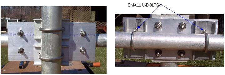
5 ( ) Pass a #6 x 1/2" screw through the lug on one of the center conductors of the phasing line. ( ) Install a #6 star lockwasher and then pass the screw through the hole in one of the T- Match Rods. ( ) Screw the screw firmly into one of the black Delrin support insulators. ( ) Refer to Figure 5 and install a shorting block on the outer end of the T-rod and driven element. ( ) Dress the phasing line toward the rear of the antenna. ( ) Align the T-rod until it is parallel to the driven element. Do not secure the shorting block at this time. Read before proceeding with the next step. If more than one antenna is to be used, be certain that the coax center conductor always feeds to the same side of the driven element for all antennas. For vertical stacking the lower antennas may be mounted with coax feed upward but be certain that you reverse the feed direction of the T-match, so that all antennas are fed to the same side of the boom. ( ) Pass a #6 x 1/2" screw through the lug attached to the braided wire center conductor of the N-Connector. ( ) Slide on a #6 star lockwasher then pass the screw through the lug on the remaining center conductor of the Balun/phasing line. ( ) Slide another #6 star lockwasher onto the screw and then pass the screw through the second T-rod and screw it into the second black Delrin insulator. ( ) Again refer to Figure 5 and install a shorting block between the outer end of the T-rod and the driven element. Do not secure the shorting block at this time. ( ) Check and make certain that both T-Match Rods are parallel to the driven element and the shorting blocks are perpendicular to the rod and element. ( ) The outer edge of the shorting blocks should be 12.5 mm for 144 MHz or 4.5 for 147 MHz from the end of the T-Match rod. If the shorting blocks are not at a distance of 12.5mm or 4.5 mm adjust their location and tighten the #8 machine screws. ( ) In the next step be very careful not to bend or twist the balun coaxial cable otherwise damage will occur to the balun cable which is not covered by warranty. ( ) Use the #6 x 3/8" sheet metal screw and black cable clamp to fasten and dress the phasing line to the rear of the boom, again being careful not to twist the cable. ( ) Attach the boom to mast plate to the boom midway between elements D-5 and D-6 (see Figures 1B and 3). Use 1 3/8" saddles and the 1-1/2" SS U-bolts with 1/4" stainless nuts and lockwashers. The antenna will be front heavy at this point but the weight of the feedline, when attached, will cause it to be balanced. If using multiple antennas in an array, be certain that all mounting plates are at the same location. When attaching the antenna to your mast, use the 5/16-18 U-Bolts, associated hardware and saddles provided (Refer to Figure 3). ( ) Place the 1 1/4" RED end caps on the ends of the antenna boom. Place the 1/2" RED end caps on the DE and the 3/8" RED end caps on the T-Match rods. 5
6 ( ) At this point the antenna can be tuned for final adjustment if a directional watt meter or return loss bridge is available. Support the antenna about 8 ft. above the ground and point it in a direction clear of anyobstructions for a distance of 100 ft. minimum. DO NOT USE A POWER LEVEL ABOVE 10 WATTSWHILE MAKING ADJUSTMENTS. DO NOT STAND IN FRONT OF THE ANTENNA. THE RF LEVEL WILL BE DANGEROUSLY HIGH. Slide the shorting blocks in or out in very small increments until the best VSWR is obtained. The VSWR should be less than 1.5:1 at 144 MHz or 147 MHz with the dimensions given. Coat the driven element, insulators, standoffs, and all keepers with a clear weather proof lacquer. KRYLON #1301 or 1302 is highly recommended. Three or four coats will protect the antenna from corrosion for many years. Do not coat the antenna until final swr measurements have been made. Stacking distances for optimum gain to noise temperature ratio are: E-plane1 l ft 6in H-plane10 ft 6in WARNING: INSTALLATION OF THIS PRODUCT NEAR POWER LINES IS DANGEROUS. FOR YOUR SAFETY FOLLOW THE INSTALLATION DIRECTIONS. REFER TO THE ENCLOSED PAMPHLET TO DETERMINE A PROPER MOUNTING LOCATION. 6
7 90 Day Limited Warranty for Antennas/Accessories Ariane Arrays warrants to the first consumer purchaser that the device purchased is free from defects in material and workmanship. During the first 90 days from date of consumer purchase, Ariane Arrays sole obligation under this warranty shall be to repair or replace (at the company's option) the device. Normal replacement parts are covered by this warranty. This warranty is the sole and exclusive express warranty given with respect to the product and all other express warranties are hereby excluded. The company and its dealers are not responsible for indirect, incidental, or consequential damages. Some States do not allow the exclusion of limitation on incidental or consequential damages, so the above limitation may not apply to you. This warranty does not extend to any defect, malfunction, or failure caused by misuse, abuse, accident, faulty hookup, modification, or defective associated equipment. Please read our instruction sheets carefully and contact us if there are any questions prior to applying voltage to the unit. Ariane Arrays retains final determination authority regarding the status of any device returned for warranty service. This warranty is valid only when the device is returned directly to Ariane Arrays at the above address. The device should be packaged carefully and in a like manner to the packaging in which the unit was delivered. It should be sent pre-paid, along with a copy of purchase receipt. This warranty gives you specific legal rights and you may have other rights which vary from State to State. Ariane Arrays reserves the right to make engineering changes as required to improve products. Please contact us either by phone or describing the problem and we will resolve your problem. DO NOT RETURN ANYTHING WITHOUT PRIOR AUTHORIZATION FROM ARIANE ARRAYS. IF AN ANTENNA IS SO MODIFIED AS TO MAKE IT IN ANY FORM DIFFERENT FROM WHAT IT WAS WHEN MANUFACTURED, ARIANE ARRAYS RESERVES THE RIGHT TO REFUSE TO ACCEPT THE ANTENNA FOR RETURN. This warranty gives you specific legal rights and you may have other rights which vary from State to State. Ariane Arrays reserves the right to make engineering changes as required to improve products. Please contact us either by phone or describing the problem and we will resolve your problem. DO NOT RETURN ANYTHING WITHOUT PRIOR AUTHORIZATION FROM ARIANE ARRAYS. IF AN ANTENNA IS SO MODIFIED AS TO MAKE IT IN ANY FORM DIFFERENT FROM WHAT IT WAS WHEN MANUFACTURED, ARIANE ARRAYS RESERVES THE RIGHT TO REFUSE TO ACCEPT THE ANTENNA FOR RETURN. 7
8 Rev 12/05/06 Figure 1A
9 Rev 12/05/06 Figure 1B


10 Figure 5 Figure 2 Figure 3 Figure 4 Rev 12/05/06
11 Electrical Specifications: Measured Gain dbi E-plane 3dB beamwidth...34 degrees H-plane 3dB beamwidth...37 degrees Bandwidth (F ) MHz Bandwidth (F ) MHz Sidelobe attenuation: 1st E-plane db 1st H-plane db VSWR...Less Than 1.5:1 typical Front to Back ratio...22 db Impedance...50 ohms nominal Maximum input power Watts Optimum stacking distance: E-Plane...11 ft. 6 in. H-Plane...10 ft. 6 in. Mechanical Specifications: Boom Length...17 ft. 4 in. Boom material t6 aluminum alloy Boom sizes: Center section " OD x.058 wall End sections " OD x.058 wall Turning radius...10 ft. 6 in. Wind survival MPH Wind surface area sq. ft. Assembled weight lbs. Element material...1/4" Aluminum rod Connector type...waterproof N type Balun...RG142 Teflon coax Maximum Mast size...2 in. OD All elements insulated with UV-resistant black Celcon M90 Rev 12/5/06
Directive Systems & Engineering 2702 Rodgers Terrace Haymarket, VA
 Directive Systems & Engineering 2702 Rodgers Terrace Haymarket, VA 20169 1628 www.directivesystems.com 703 754 3876 K1JX DESIGNED 6 ELEMENT 50 MHZ YAGI, DSEJX6 50 INTRODUCTION The Directive Systems DSEJX6-50
INSTRUCTION MANUAL. Specifications Electrical. Front-To-Back Ratio VSWR at Resonance Less than 1.5:1 Nominal Impedance. Mechanical
 300 Industrial Park Road, Starkville, MS 39759 Ph: (662) 323-8538 FAX: (662) 323-6551 TH-3JRS Tri-band HF 3 Elements Beam Covers 10, 15 and 20 Meters INSTRUCTION MANUAL WARNING Installation of this product
INSTRUCTION MANUAL. Specifications Mechanical. 1 5/8 to 2 1/16 O.D. (41mm to 52mm)
") 308 Industrial Park Road Starkville, MS 39759 USA Ph: (662) 323-9538 FAX: (662) 323- General Description Model VB-25FM 2-Meter 5 Elements Beam INSTRUCTION MANUAL This antenna is a 5-element, 2-meter beam
308 Industrial Park Road Starkville, MS 39759 USA Ph: (662) 323-9538 FAX: (662) 323- General Description Model VB-25FM 2-Meter 5 Elements Beam INSTRUCTION MANUAL This antenna is a 5-element, 2-meter beam
Model VB-23FM 2-Meter 3-Element Beam
 308 Industrial Park Road Starkville, MS 39759 USA Ph: (662) 323-9538 FAX: (662) Model VB-23FM 2-Meter 3-Element Beam [ INSTRUCTION MANUAL Figure 1 Overall View and Boom Detail GENERAL DESCRIPTION This
Directive Systems & Engineering 2702 Rodgers Terrace Haymarket, VA
 Directive Systems & Engineering 2702 Rodgers Terrace Haymarket, VA 20169-1628 www.directivesystems.com 703-754-3876 25 Element 7.4 wl. K1FO Designed Yagi, Model DSEFO432-25 ELECTRICAL SPECIFICATIONS Frequency
LJ element beam for 10 or 12 meters INSTRUCTION MANUAL. CAUTION: Read All Instructions Before Operating Equipment
 LJ-113 3 element beam for 10 or 1 meters INSTRUCTION MANUAL CAUTION: Read All Instructions Before Operating Equipment 308 Industrial Park Road Starkville, MS 39759 USA Tel: 66-33-9538 Fax: 66-33-6551 VERSION
M2 Antenna Systems, Inc. Model No: 2M7
 M2 Antenna Systems, Inc. Model No: 2M7 SPECIFICATIONS: Model... 2M7 Frequency Range... 144 To 148 MHz *Gain... 12.3 dbi Front to back... 20 db Typical Beamwidth... E=43 H=50 Feed type... T Match Feed Impedance....
JK-65 Five Element 6M Yagi
 JK-65 Five Element 6M Yagi PO Box 266, Croton Falls, NY 10519-0266 845.228.8700 (TEL) 845.279.5526 (FAX) info@jkantennas.com Page 1 of 8 JK Antennas Limited Warranty and Liability JK Antennas ( Manufacturer
INSTRUCTION MANUAL V-42R. Dual Band Collinear Gain Vertical for MHz and GENERAL DESCRIPTION
 308 Industrial Park Road, Starkville, MS 39759 USA Ph: (662) 323-9538 FAX: (662) 323-6551 V-42R Dual Band Collinear Gain Vertical for 144-148 MHz and 436-450 INSTRUCTION MANUAL GENERAL DESCRIPTION The
THIS SHOULD TWEAK YOUR IMAGINATION
 10-27-05 THIS SHOULD TWEAK YOUR IMAGINATION SPECIFICATIONS FOR SINGLE ANTENNA MODEL NUMBER... 432EME-12 FREQUENCY... 430-436 MHz GAIN... 14.4 dbd FRONT TO BACK... 23 db VSWR... 1.2:1 TYPICAL BEAMWIDTH...
INSTRUCTION MANUAL. Model VB-215DX MECHANICAL DESIGN GENERAL DESCRIPTION ELECTRICAL DESIGN. 2 Meter 15 Element Yagi for SSB/CW
 Model VB-215DX 2 Meter 15 Element Yagi for SSB/CW INSTRUCTION MANUAL GENERAL DESCRIPTION The Hy-Gain Model 215DX is a high performance yagi antenna for SSB/CW DXing in the Amateur 2 meter band. It features
M2 Antenna Systems, Inc. Model No: KT31WARC
 M2 Antenna Systems, Inc. Model No: KT31WARC SPECIFICATIONS: Model... KT31WARC Frequency Range... 10.1-10.15 MHz **Selectable Frequency Range... 14.0-14.35 MHz **Selectable... (175 KHz / 2:1 VSWR Nominal)
ASSEMBLY AND INSTALLATION INSTRUCTIONS R , 12, 15, 17, 20, 30, 40 Meters (5/99) COMMUNICATIONS ANTENNAS
 COMMUNICATIONS ANTENNAS") ASSEMBLY AND INSTALLATION INSTRUCTIONS R7000 10, 12, 15, 17, 20, 30, 40 Meters COMMUNICATIONS ANTENNAS 951465 (5/99) WARNING THIS ANTENNA IS AN ELECTRICAL CONDUCTOR. CONTACT WITH POWER LINES CAN RESULT
ASSEMBLY AND INSTALLATION INSTRUCTIONS R7000 10, 12, 15, 17, 20, 30, 40 Meters COMMUNICATIONS ANTENNAS 951465 (5/99) WARNING THIS ANTENNA IS AN ELECTRICAL CONDUCTOR. CONTACT WITH POWER LINES CAN RESULT
M2 Antenna Systems, Inc. Model No: 2M4
 M2 Antenna Systems, Inc. Model No: 2M4 SPECIFICATIONS: Model... 2M4 Frequency Range... 144 To 148 MHz *Gain... 9.6 dbi Front to back... 20 db Typical Beamwidth... E=54 H=74 Feed type... T Match Feed Impedance....
JK M Hi-Q Coil Loaded Rotatable Dipole Version
 JK-401 40M Hi-Q Coil Loaded Rotatable Dipole 2018 Version 72 Grays Bridge Road, Unit D, Brookfield, CT 06804 845.228.8700 (TEL) 845.279.5526 (FAX) info@jkantennas.com LAST UPDATED: 02-01-2018 JK Antennas
M2 Antenna Systems, Inc. Model No: 450CP34
 M2 Antenna Systems, Inc. Model No: 450CP34 SPECIFICATIONS: Model... 450CP34 Frequency Range... 435 To 455 mhz *Gain... 16.0 dbi Front to back... 22 db Typical Beamwidth... 28 Circular Feed type... T Match
Installation Instructions Hustler Collinear Two Meter Fixed Station Antenna Master Gainer Model G6-144B
 Installation Instructions Hustler Collinear Two Meter Fixed Station Antenna Master Gainer Model Warning INSTALLATION OF THIS PRODUCT NEAR POWER LINES IS DANGEROUS. FOR YOUR SAFETY, FOLLOW THE INSTALLATION
M2 Antenna Systems, Inc. Model No: 450CP26
 M2 Antenna Systems, Inc. Model No: 450CP26 SPECIFICATIONS: Model... 450CP26 Frequency Range... 445 To 455 mhz *Gain... 16.5 dbi Front to back... 21 db Typical Beamwidth... 30 Circular Feed type... T Match
INSTRUCTION MANUAL VB-66DX. 6-Meter 6-Element Beam. Preparation For Assembly. General Description
 VB-66DX 308 Industrial Park Road Starkville, MS 39759 USA Ph: (662) 323-9538 FAX: (662) 323-6551 6-Meter 6-Element Beam INSTRUCTION MANUAL General Description The Hy-Gain Model 66DX is a full sized 6-
MODEL DB-1015A 10- and 15-Meter Duo-Band Antenna Order No. 330
 MODEL DB-1015A 10- and 15-Meter Duo-Band Antenna Order No. 330 HY-GAIN ELECTRONICS CORPORATION 8601 Northeast Highway 6 Lincoln, Nebraska 68505 Telephone 464-9151 Area Code 402 TABLE OF CONTENTS page SECTION
M2 Antenna Systems, Inc. Model No: 20M6-125
 M2 Antenna Systems, Inc. Model No: 20M6-125 SPECIFICATIONS: Model... 20M6-125 Frequency Range... 14.0 14.350 MHz *Gain, (FS) / Over gnd... 11.19dBi / 16.6dBi @70 Front to back... 25 db Typical Beamwidth...
INSTRUCTION MANUAL. Model 18AVQII Five Band Vertical Antenna 10, 15, 20, 40, 80 Meter. General Description. Theory of Operation
 Model 18AVQII Five Band Vertical Antenna 10, 15, 20, 40, 80 Meter 308 Industrial Park Road Starkville, MS 39759 (662) 323-9538 Fax: (662) 323-5803 INSTRUCTION MANUAL General Description The Hy-Gain 18AVQII
M2 Antenna Systems, Inc. Model No: YAGI ANTENNA
 M Antenna Systems, Inc. Model No: 4.5-7 YAGI ANTENNA SPECIFICATIONS: Model... 4.5-7 Frequency Range... 4.0 To 4.5 MHz *Gain... 0 To 7 dbi Front to back... 0 db over the rear 80 Beamwidth... E=44 H=50 typical
INSTRUCTION MANUAL ORDER NO. V3R MODEL V3R. Collinear Gain Vertical for MHz
 ORDER NO. V3R MODEL V3R Collinear Gain Vertical for 216-225 MHz INSTRUCTION MANUAL General Description The new Hy-Gain V3R VHF antenna is a collinear 5/8-wave omnidirectional vertical antenna for the 216-225
C O R P O R A T I O N
 ASSEMBLY AND INSTALLATION INSTRUCTIONS A4S 20 / 5 / 0 MeterBeam C O R P O R A T I O N 95279 (8/98) WARNING THIS ANNNA IS AN ELECTRICAL CONDUCTOR. CONTACT WITH POWER LINES CAN RESULT IN DEATH, OR SERIOUS
MFJ Instruction Manual Table of Contents
 Table of Contents MFJ-1768 Introduction...2 Choosing a Location for the Antenna...2 Tools and Time Requirements...3 MFJ-1768 Parts List...3 Safety Precautions...3 Assembly and Installation...4 Tuning...7
TENNADYNE. Aluminum with a PhD. Tennadyne ASSEMBLY INSTRUCTIONS MODEL: T Log Periodic Antennas SPECIFICATIONS:
 TENNADYNE Aluminum with a PhD ASSEMBLY INSTRUCTIONS MODEL: T10-100224 SPECIFICATIONS: FREQUENCY COVERAGE 13-33 MHz FORWARD GAIN 6.1 dbd ½ POWER BEAMWIDTH 52 DEGREES F:B RATIO To 25 Db (Rises with frequency)
INSTRUCTION MANUAL for MODEL TH6-DX "THUNDERBIRD" (389)
") INSTRUCTION MANUAL for MODEL TH6-DX "THUNDERBIRD" (389) HY-GAIN ELECTRONICS CORPORATION, N. E. Hwy #6 at Stevens Creek, Lincoln, Nebraska 65801 Telephone 434-6331 INTRODUCTION Ely-Gain's new Model TH6-DX
INSTRUCTION MANUAL for MODEL TH6-DX "THUNDERBIRD" (389) HY-GAIN ELECTRONICS CORPORATION, N. E. Hwy #6 at Stevens Creek, Lincoln, Nebraska 65801 Telephone 434-6331 INTRODUCTION Ely-Gain's new Model TH6-DX
M2 Antenna Systems, Inc. Model No: 436CP30
 M2 Antenna Systems, Inc. Model No: 436CP30 SPECIFICATIONS: Model... 436CP30 Frequency Range... 432 To 440 MHz *Gain... 15.50 dbic Front to back... 18 db Typical Elipticity... 1.5 db Typical Beamwidth...
M2 Antenna Systems, Inc. Model No: 40M3L
 M2 Antenna Systems, Inc. Model No: 40M3L SPECIFICATIONS: Model... 40M3L Frequency Range... 7.0-7.3 MHz X 150 khz Gain... 6.6 dbi Front to back... 23 db Beamwidth... E=62 Feed type... Hair pin match Feed
Cushcraft. Amateur Radio Antennas DB-46M8EL. Dual band 6 and 4 Meter, 8 Element Beam Antenna INSTRUCTION MANUAL
 Cushcraft Amateur Radio Antennas DB-46M8EL Dual band 6 and 4 Meter, 8 Element Beam Antenna INSTRUCTION MANUAL CAUTION: Read All Instructions Before Operating Equipment VERSION 1B Cushcraft Amateur Radio
JK NAVASSA-5. 5-Band Yagi (20M/17M/15M/12M/10M) Optional 6M Add-on Kit Available
 Optional 6M Add-on Kit Available") JK NAVASSA-5 5-Band Yagi (20M/17M/15M/12M/10M) Optional 6M Add-on Kit Available 72 Grays Bridge Road, Unit D, Brookfield, CT 06804 845.228.8700 (TEL) 845.279.5526 (FAX) info@jkantennas.com Last Updated:
JK NAVASSA-5 5-Band Yagi (20M/17M/15M/12M/10M) Optional 6M Add-on Kit Available 72 Grays Bridge Road, Unit D, Brookfield, CT 06804 845.228.8700 (TEL) 845.279.5526 (FAX) info@jkantennas.com Last Updated:
M2 Antenna Systems, Inc. Model No: 2M5WL
 M2 Antenna Systems, Inc. Model No: 2M5WL SPECIFICATIONS: Model... 2M5WL Frequency Range... 144 To 148 MHz *Gain... 16.84 dbi Front to back... 22 db Typical Beamwidth... E=26 H=29 Feed type... T Match Feed
M2 Antenna Systems, Inc. Model No: 20M5LD
 M2 Antenna Systems, Inc. Model No: 20M5LD SPECIFICATIONS: Model... 20M5LD Frequency Range... 14.0 14.350 MHz *Gain (Full Band)... 10.2 dbi Typical Front to back... 23 db Typical Beamwidth... E=50 / H=66
M2 Antenna Systems, Inc. Model No: 456CP34
 M2 Antenna Systems, Inc. Model No: 456CP34 SPECIFICATIONS: Model... 456CP34 Frequency Range... 435 To 470 mhz *Gain... 16.0 dbi Front to back... 23 db Typical Beamwidth... 30 Circular Feed type... T Match
MI: (Secure this number someplace, for possible future need) SPECIFICATIONS:
 SPECIFICATIONS:") 6C ASSEMBLY INSTRUCTIONS ANTENNA MODEL T6 MI: 030927 (Secure this number someplace, for possible future need) SPECIFICATIONS: FORWARD GAIN 5.1 dbd F:B RATIO 15-25 db (Rises with frequency) FREQUENCY COVERAGE
6C ASSEMBLY INSTRUCTIONS ANTENNA MODEL T6 MI: 030927 (Secure this number someplace, for possible future need) SPECIFICATIONS: FORWARD GAIN 5.1 dbd F:B RATIO 15-25 db (Rises with frequency) FREQUENCY COVERAGE
Cushcraft. Amateur Radio Antennas LFA-6M5EL. 6 Meter 5 Element Loop Feed Antenna INSTRUCTION MANUAL
 Cushcraft Amateur Radio Antennas LFA-6M5EL 6 Meter 5 Element Loop Feed Antenna INSTRUCTION MANUAL CAUTION: Read All Instructions Before Operating Equipment VERSION 1A Cushcraft Amateur Radio Antennas 308
M2 Antenna Systems, Inc. Model No: 2MCP22
 M2 Antenna Systems, Inc. Model No: 2MCP22 SPECIFICATIONS: Model... 2MCP22 Frequency Range... 144 To 148 MHz *Gain... 14.39 dbic Front to back... 25 db Typical Elipticity... >3db Beamwidth... 38 Feed type...
MFJ-2100 INSTRUCTION MANUAL. CAUTION: Read All Instructions Before Operating Equipment
 MFJ-2100 INSTRUCTION MANUAL CAUTION: Read All Instructions Before Operating Equipment 300 Industrial Park Road Starkville, MS 39759 USA Tel: 662-323-5869 Fax: 662-323-6551 COPYRIGHT C 2015 MFJ Enterprises
JK BigTri. 3-Band Yagi (20M/15M/10M) 36Ft Boom
 36Ft Boom") JK BigTri 3-Band Yagi (20M/15M/10M) 36Ft Boom 72 Grays Bridge Road, Unit D, Brookfield, CT 06804 845.228.8700 (TEL) 845.279.5526 (FAX) info@jkantennas.com UPDATED : FEB 2017 JK Antennas Limited Warranty
JK BigTri 3-Band Yagi (20M/15M/10M) 36Ft Boom 72 Grays Bridge Road, Unit D, Brookfield, CT 06804 845.228.8700 (TEL) 845.279.5526 (FAX) info@jkantennas.com UPDATED : FEB 2017 JK Antennas Limited Warranty
Installation Instructions Hustler 6-BTV Trap Vertical
 Installation Instructions Hustler 6-BTV Trap Vertical ASSEMBLY 1. Check the package contents against the parts list on page 2. 2. WARNING. Installation of this product near power lines is dangerous. For
This file was downloaded from the website of G7SYW.
 This file was downloaded from the website of G7SYW http://www.g7syw.co.uk ASSEMBLY AND INSTALLATION INSTRUCTIONS Five-Band High-Performance Mini-Vertical Antenna 951495 (8/01) WARNING THIS ANTENNA IS AN
TELEX, liutiiilio"i TELEX COMMUNICATIONS, INC ALDRICH AVE. SO. MINNEAPOLIS. MN USA
 TELEX, liutiiilio"i TELEX COMMUNICATIONS, INC. 9600 ALDRICH AVE. SO. MINNEAPOLIS. MN 55420 USA INSTRUCTION MANUAL ORDER NO. 410 General This antenna is a five-element, Citizens Band beam with a forward
JK-404 GRANDE Four Element Full Size 40M Yagi
 JK-404 GRANDE Four Element Full Size 40M Yagi PO Box 266, Croton Falls, NY 10519-0266 845.228.8700 (TEL) 845.279.5526 (FAX) info@jkantennas.com JK Antennas Limited Warranty and Liability JK Antennas (
DB Duo-Monoband Beam 7 - Element, 12 and 17 Meter INSTRUCTION MANUAL. General Description
 308 Industrial Park Road Starkville, MS 39759 USA Ph: (662) 323-9538 FAX: (662) 323-6551 DB- 1217 Duo-Monoband Beam 7 - Element, 12 and 17 Meter INSTRUCTION MANUAL General Description The Hy-Gain DB-1217
M2 Antenna Systems, Inc. Model No:
 M2 Antenna Systems, Inc. Model No: 400-600-10 SPECIFICATIONS: Model... 400-600-10 Frequency Range... 390 To 650 MHz *Gain... 12 To 13 dbic Front to back... 20 db Nominal Beamwidth... 46 Nominal Feed Impedance....
MOUNTING INSTRUCTIONS
 Standard Mounting Bracket Tilting Bracket* Mounting example Right side for upper tilt from 0 to 20 20 Spare parts: p/n SA197 Materials: extruded aluminum Hardware: stainless & zinc plated steel Dimensions
TELEX. iiilhiijiri INSTRUCTION MANUAL ORDER NO. 411 TELEX COMMUNICATIONS, INC ALDRICH AVE SO. MINNEAPOLIS. MN U.SA.
 TELEX. iiilhiijiri TELEX COMMUNICATIONS, INC. 9600 ALDRICH AVE SO. MINNEAPOLIS. MN 55420 U.SA. INSTRUCTION MANUAL ORDER NO. 411 Base Station, 5-Element Beam Antenna This antenna is a five element, Citizens
Installation Instructions Hustler 6-BTV Trap Vertical
 Installation Instructions Hustler 6-BTV Trap Vertical ASSEMBLY 1. Check the package contents against the parts list on page 2. 2. WARNING. Installation of this product near power lines is dangerous. For
INSTRUCTION MANUAL. Model 18AVQII Five Band Vertical Antenna 10, 15, 20, 40, 80 Meter
 Model 18AVQII Five Band Vertical Antenna 10, 15, 20, 40, 80 Meter 308 Industrial Park Road Starkville, MS 39759 (662) 323-9538 Fax: (662) 323-5803 INSTRUCTION MANUAL General Description The Hy-Gain 18AVQII
9el 144MHZ LFA YAGI ASSEMBLY & INSTALLATION MANUAL
 1 9el 144MHZ LFA YAGI ASSEMBLY & INSTALLATION MANUAL 2 WARNING EXTREME CAUTION SHOULD BE TAKEN WHEN CONSTRUCTING AND ERECTING ANTENNA SYSTEMS NEAR POWER AND TELEPHONE LINES. SERIOUS INJURY OR DEATH CAN
M2 Antenna Systems, Inc. Model No: 10-30LP8
 M2 Antenna Systems, Inc. Model No: 10-30LP8 SPECIFICATIONS: Model... 10-30LP8 Frequency Range... 10-30 MHz Continuous *Gain free space / 65... 5.2 dbi / 10.5 dbi 10-30 Front to back... 15 db 10-30 MHz
TW4040. The Adventurer Monobander INSTRUCTION MANUAL. TransWorld Antennas
 TW4040 The Adventurer Monobander TransWorld Antennas INSTRUCTION MANUAL Contents 1 Limited Warranty 3 2 Important Safety Information 4 3 Specifications 3.1 Mechanical 4 3.2 Electrical 4 3.3 VSWR Performance
M2 Antenna Systems, Inc. Model No: 40M2L
 M2 Antenna Systems, Inc. Model No: 40M2L SPECIFICATIONS: Model...40M2L Frequency Range...6.9-10 MHz X 150 khz Gain...5.5 dbi Front to back...13 15 db Beamwidth...E=74 Feed type...hair pin match Feed Impedance....50
INSTRUCTION MANUAL. Model BN-4000B. High Power Balun for Beams with Type SO-239. Construction. General Description. Mounting on Boom or Mast
 308 Industrial Park Starkville, MS 39759 USA Ph: (662) 323-9538 FAX: (662) 323 6551 Model BN-4000B High Power Balun for Beams with Type SO-239 INSTRUCTION MANUAL General Description The BN-4000 is a current-type
TZ-RD-1740 Rotary Dipole Instruction Manual
 TZ-RD-1740 17/40m Rotary Dipole Instruction Manual The TZ-RD-1740 is a loaded dipole antenna for the 40m band and a full size rotary dipole for the 17m band. The antenna uses an aluminium radiating section
PACKING LIST MACO V-5000
 PACKING LIST MACO V-5000 PART QTY O.D. SIZE LENGTH DESCRIPTION CHECKLIST T47P 4 5/8.050 36 Aluminum Tubing _ T43P 1 7/8.050 48 Aluminum Tubing _ T18P 1 3/4.050 48 Aluminum Tubing _ T15P 1 5/8.050 48 Aluminum
MFJ ENTERPRISES, INC.
 Model MFJ-2911 INSTRUCTION MANUAL CAUTION: Read All Instructions Before Operating Equipment MFJ ENTERPRISES, INC. 300 Industrial Park Road Starkville, MS 39759 USA Tel: 662-323-5869 Fax: 662-323-6551 VERSION
CP6A. 6 Band Trap Vertical 75-6m
 CP6A 6 Band Trap Vertical 75-6m Instruction Sheet The CP6A is a multi-band trap-vertical antenna for HF bands, covering the 75*, 40, 20, 15, 10m & 6m amateur bands. Made from heavy duty aluminum, the CP6A
00108/00110 INSTRUCTION MANUAL
 00108/00110 INSTRUCTION MANUAL Removable and Adjustable Mudflap System IMPORTANT! Please Read this Instruction Booklet prior to assembly of your Rock Tamer Kit. IMPORTANT! Exhaust Systems Note: Any modifications
M2 Antenna Systems, Inc. Model No: 435XP50
 M2 Antenna Systems, Inc. Model No: 435XP50 SPECIFICATIONS: Model... 435XP50 Frequency Range... 430 To 436 MHz *Gain... 19.2 dbi Front to back... 22 db Typical Cross pol. isolation... >20 db Typical Beamwidth...
Cisco Aironet 13.5-dBi Yagi Mast Mount Antenna (AIR-ANT1949)
") Cisco Aironet 13.5-dBi Yagi Mast Mount Antenna (AIR-ANT1949) Overview This document describes the 13.5-dBi Yagi mast mount antenna and provides instructions for mounting it. The antenna operates in the
Cisco Aironet 13.5-dBi Yagi Mast Mount Antenna (AIR-ANT1949) Overview This document describes the 13.5-dBi Yagi mast mount antenna and provides instructions for mounting it. The antenna operates in the
MFJ-1799 INSTRUCTION MANUAL. 2,6,10,12,15,17,20,30,40,80 METER Vertical Antenna. CAUTION: Read All Instructions Before Operating Equipment
 MFJ-799,6,0,,5,7,0,30,40,80 METER Vertical Antenna INSTRUCTION MANUAL CAUTION: Read All Instructions Before Operating Equipment 300 Industrial Park Road Starkville, MS 39759 USA Tel: 66-33-5869 Fax: 66-33-655
MFJ-1835K34 40,30 METER ADD ON KIT FOR THE MFJ-1835 COBWEB ANTENNA INSTRUCTION MANUAL. CAUTION: Read All Instructions Before Operating Equipment
 MFJ-1835K34 40,30 METER ADD ON KIT FOR THE MFJ-1835 COBWEB ANTENNA INSTRUCTION MANUAL CAUTION: Read All Instructions Before Operating Equipment 300 Industrial Park Road Starkville, MS 39759 USA Tel: 662-323-5869
MFJ-2982 Feather-Lite 80-6 Meter Vertical Antenna
 MFJ-2982 Feather-Lite 80-6 Meter Vertical Introduction: The MFJ-2982 is a lightweight 31-foot fiberglass antenna designed to mount on any convenient post, mast, or a suitable wide-stance tripod such as
M2 Antenna Systems, Inc. Model No: 10-30LP8
 M2 Antenna Systems, Inc. Model No: 10-30LP8 VSWR 2:1 TYPICAL VSWR @ 70 FT. 2:1 1.5:1 1.5:1 1.2:1 1.2:1 10 14 MHz 11 12 13 17 15 16 18 19 20 21 22 23 24 25 26 27 28 29 30 SPECIFICATIONS: Model...10-30LP8
TENNADYNE TD-160HP800
 TENNADYNE Aluminum with a PhD ASSEMBLY INSTRUCTIONS TD-160HP800 SPECIFICATIONS: Impedance: 50 Ohm nominal Bandwidth :1.8-30 MHz Length : 160 ft. Power : 8 KW Impulse 2400 W PEP SSB 800 W AM/FM/RTTY Connector
M2 Antenna Systems, Inc. Model No: 2M HO LOOP
 M2 Antenna Systems, Inc. Model No: 2M HO LOOP SPECIFICATIONS: Model... 2M HO LOOP Frequency Range... 144 To 144.5 MHz Gain, Typical @ 10 ft.... 4 dbd @ 10 deg. Gain, 2 STK @ 82 & 132... 8 dbd @ 9 deg.
Construction manual for 50 MHz XL design yagi-kits
 Construction manual for 50 MHz XL design yagi-kits Source: http://www.nuxcom.de/pdf/nuxcom_construction-manual_6m-xl.pdf Please check if all parts listed in the invoice are delivered with the kit. In the
Cisco Aironet 12 dbi High Gain Omnidirectional Antenna (AIR-ANT24120)
") Cisco Aironet 12 dbi High Gain Omnidirectional Antenna (AIR-ANT24120) Overview This document outlines the specifications and description of the 12-dBi high gain omnidirectional antenna. This antenna operates
Cisco Aironet 12 dbi High Gain Omnidirectional Antenna (AIR-ANT24120) Overview This document outlines the specifications and description of the 12-dBi high gain omnidirectional antenna. This antenna operates
Assembly Instructions: Bencher Skylark
 Assembly Instructions: Bencher Skylark Tools Required: Pop Rivet Tool Tape Measure Hex Wrenches Screwdriver Several Disposable Rags Two Saw Horses Several boxes or bowls to hold fasteners and small parts
HMS Hairpin Matching Systems
 HMS Hairpin Matching Systems DXE-HMS-1P, DXE-HMS-2P, DXE-HMS-4P DXE-HMS-INS-Rev 1h For Use with 1-1/4 Inch through 3 Inch Booms Shown with optional Boom, Elements and Element Bracket with Gorilla Grip
Spiderbeam Balun Construction Guide
 BALUN CONSTRUCTION GUIDE Ver. 1.0 1 The components of the Balun Kit are in a plastic bag. Most of the components are inside the plastic case of the balun. The aluminum U-profile and the RG-142 Teflon Coax
M2 Antenna Systems, Inc. Model No: 7&10-30LP8
 M2 Antenna Systems, Inc. Model No: 7&10-30LP8 2:1 100KHz BANDWIDTH@ 1.8:1 VSWR 1.5:1 6.9 7.0 7.1 10 FREQUENCY (MHZ) 20 SPECIFICATIONS: Model...7&10-30LP8 Skip log Frequency Range...10-30 MHz Continuous
Chapter 6 Antenna Basics. Dipoles, Ground-planes, and Wires Directional Antennas Feed Lines
 Chapter 6 Antenna Basics Dipoles, Ground-planes, and Wires Directional Antennas Feed Lines Some General Rules Bigger is better. (Most of the time) Higher is better. (Most of the time) Lower SWR is better.
40 Meter Vertical Antenna
 40 Meter Vertical Antenna COM-40VA COM-40VA-INS-Revision 1 COMTEK SYSTEMS 2016 1200 Southeast Ave. - Tallmadge, OH 44278 USA Phone: (800) 777-0703 Technical Support and International: (330) 572-3200 Fax:
9 Element Yagi for 2304 MHz
 9 Element Yagi for 2304 MHz Steve Kavanagh, VE3SMA Design Dipole-based Yagi designs for 2304 MHz are rare, partly because they are a bit tricky to build and partly because the loop yagi has completely
Tilting & Swiveling Plasma/LCD Flat Panel Wall Mount Installation Guide Model: A380SM
 Tilting & Swiveling Plasma/LCD Flat Panel Wall Mount Installation Guide Model: A380SM Easy installation Built-in level for easy positioning Corrective leveling adjustments after installation Forward /
TELEX COMMUNICATIONS, INC ALDRICH LIVE SO. MINNEAPOLIS. MN U S A. /~g-~~~~r iu IORDER NO. 337s
 IkEfEX N TELEX COMMUNICATIONS, INC. 300 ALDRICH LIVE SO. MINNEAPOLIS. MN 55420 U S A /~g-~~~~r iu IORDER NO. 337s MAN A I MODEL V4S Collinear Gain Vertical for 420450 MHz PN801910 General Description The
HP ProCurve 6.9/7.7dBi Dual Band Directional Antenna (J8999A) Guide
 Guide") HP ProCurve 6.9/7.7dBi Dual Band Directional Antenna (J8999A) Guide SAFETY The HP ProCurve J8999A and all associated equipment should be installed in accordance with applicable local and national electrical
HP ProCurve 6.9/7.7dBi Dual Band Directional Antenna (J8999A) Guide SAFETY The HP ProCurve J8999A and all associated equipment should be installed in accordance with applicable local and national electrical
M2 Antenna Systems, Inc. Model No: 10-30LP8-125
 M2 Antenna Systems, Inc. Model No: 10-30LP8-125 VSWR 2:1 TYPICAL VSWR @ 70 FT. 2:1 1.5:1 1.5:1 1.2:1 1.2:1 10 14 MHz 11 12 13 17 15 16 18 19 20 21 22 23 24 25 26 27 28 29 30 SPECIFICATIONS: Model...10-30LP8-125
2014 MFJ ENTERPRISES, INC.
 Model MFJ-1907 INSTRUCTION MANUAL CAUTION: Read All Instructions Before Operating Equipment MFJ ENTERPRISES, INC. 300 Industrial Park Road Starkville, MS 39759 USA Tel: 662-323-5869 Fax: 662-323-6551 VERSION
DB-2345 INSTRUCTION MANUAL. 308 Industrial Park Road Starkville, MS USA ph:(662) Fax: (662) Made in USA
 Fax: (662) Made in USA") 308 Industrial Park Road Starkville, MS 39759 USA ph:(662) 323-9538 Fax: (662) 323-5803 DB-2345 INSTRUCTION MANUAL Made in USA Hy-Gain DB2345 Dual-Band Beam INTRODUCTION The Hy-Gain DB2345 is a compact
308 Industrial Park Road Starkville, MS 39759 USA ph:(662) 323-9538 Fax: (662) 323-5803 DB-2345 INSTRUCTION MANUAL Made in USA Hy-Gain DB2345 Dual-Band Beam INTRODUCTION The Hy-Gain DB2345 is a compact
M ACS Instructions
 APPLICABLE MODELS: Nissan Frontier 2005 and up short bed with Utili-Trak mounting rails PACKAGE CONTENTS 00-0060-M-01-1205 ACS Instructions Leitner Designs 25675 Taladro Circle Unit E Mission Viejo, CA
The MFJ-1754 can be mounted on any 1" to 1 1/2" mast (conductive or non conductive.)
") INTRODUCTION: The MFJ-1754 is designed for use on the 2 meter and the 70 centimeter bands. On the 2 meter band the MFJ-1754 behaves as a vertical 1/4 wave antenna, however on 70 centimeter band the MFJ-1754
INTRODUCTION: The MFJ-1754 is designed for use on the 2 meter and the 70 centimeter bands. On the 2 meter band the MFJ-1754 behaves as a vertical 1/4 wave antenna, however on 70 centimeter band the MFJ-1754
Hy-gain. Method 1 : Completely assemble the antenna on the ground then hoist it into position using a setup as shown in Figure 1.
 Hy-gain The Hy-Gain TH6-DXX "Super Thunderbird" is a 6-element beam designed to operate on 10, 25 and 20 meters. It has four active elements on 10-meters and three active elements on 15 and 20 meters.
PREPARATION FOR ASSEMBLY
 GENERAL DESCRIPTION The Hy-Gain Model 216 SAT is a high-performance "OSCAR" (Orbiting Satellite Carrying Amateur Radio) satellite antenna for the 145.8-146.0 MHz frequency hand. It features polarization
Owner s Manual GS2010 Garden Seeder/Fertilizer. Caution: Carefully read all Rules and Instructions for Safe Operation.
 Manufacture s Limited Warranty for The limited warranty set forth below is given by Precision Products, Incorporated with respect to new merchandise purchased and used in the United States, its possessions
MHz. ANT150D, D3, D6-9 DIPOLE AND DIPOLE ARRAY 1 TO 9 dbd
 138-174 MHz ANTD, D3, D6-9 DIPOLE AND DIPOLE ARRAY 1 TO 9 dbd The Telewave ANTD series consists of single, dual, and 4-element di pole array antennas with a precision phasing harness for optimum per formance.
Array Solutions OCF Series Dipoles
 OCF Series Dipoles Fig 1 Thank you and congratulations on your purchase of the, Off- Center Fed HF Dipole Antenna System. This antenna was built with the same quality workmanship and attention to detail
Cisco Aironet Dual-Band MIMO Wall-Mounted Omnidirectional Antenna (AIR-ANT2544V4M-R)
") Cisco Aironet Dual-Band MIMO Wall-Mounted Omnidirectional Antenna (AIR-ANT2544V4M-R) This document outlines the specifications for the Cisco Aironet 2.4-GHz/5-GHz Dual-Band MIMO Wall-Mounted Omnidirectional
Cisco Aironet Dual-Band MIMO Wall-Mounted Omnidirectional Antenna (AIR-ANT2544V4M-R) This document outlines the specifications for the Cisco Aironet 2.4-GHz/5-GHz Dual-Band MIMO Wall-Mounted Omnidirectional
MFJ Foot Self-Supporting Vertical Antenna
 MFJ-2990 43-Foot Self-Supporting Vertical Antenna INTRODUCTION The MFJ-2990 is a 43-foot self-supporting vertical antenna that covers 160-6 meters with the use of an wide range antenna tuner. Because the
MFJ-1750/1752 2M BASE ANTENNA with 5/8 GROUND PLANE Instruction Manual
 MFJ-1750/1752 2M BASE ANTENNA with 5/8 GROUND PLANE Thank you for purchasing the MFJ-1750/1752. The 1750 is a 5/8 wave antenna designed for operation on 144-148 MHz. The 1752 is designed to operate on
PAC-12 Kit Contents. Tools Needed Soldering iron Phillips screwdriver Wire stripper Wrenches, 7/16 and 1/2 Terminal crimp tool Pliers Solder
 PAC-2 Kit Contents Part Quantity Screws: 8/32 x 3/8 Screws: 8-32 x 5/6 Screw: 8-32 x /4 #8 internal tooth washers #8 solder lug ring terminals Bolt: Aluminum, /4-20 x.5 /4 internal tooth washer Nut: Aluminum
MA5B 20 / 17 / 15 / 12 / 10 Meter Beam Antenna
 ASSEMBLY AND INSTALLATION INSTRUCTIONS NE 20 / 17 / 15 / 12 / 10 Meter Beam Antenna 951485_GF_AB WARNING THIS ANTENNA IS AN ELECTRICAL CONDUCTOR. CONTACT WITH POWER LINES CAN RESULT IN DEATH, OR SERIOUS
Standard Pole Mount Parabolic Antenna Mounting Instructions 3 ft. (90cm) & 4 ft. (120cm)
 & 4 ft. (120cm)") 495 R Billerica Ave. N. Billerica, MA 01862 USA Tel: (978) 459-8800 Fax: (978) 459-3310 / 8814 www.radiowavesinc.com email: sales@radiowavesinc.com Standard Pole Mount Parabolic Antenna Mounting Instructions
495 R Billerica Ave. N. Billerica, MA 01862 USA Tel: (978) 459-8800 Fax: (978) 459-3310 / 8814 www.radiowavesinc.com email: sales@radiowavesinc.com Standard Pole Mount Parabolic Antenna Mounting Instructions
Model 3104C. Biconical Antenna. User Manual
 Model 3104C Biconical Antenna User Manual ETS-Lindgren L.P. reserves the right to make changes to any product described herein in order to improve function, design, or for any other reason. Nothing contained
ProCurve 7 dbi Dual Band Directional antenna
 GROUNDING System grounding and lightning protection are essential, especially for exterior-mounted antennas exposed to the elements. Never install an antenna where it may fall and contact electrical lines
Hollywood Swing Away 2 and 4 Bike Racks Assembly and Installation Guide
 Hollywood Swing Away 2 and 4 Bike Racks Assembly and Installation Guide Tools Required: two adjustable wrenches, pliers, ¾ socket wrench recommended Note: please do assembly near your vehicle as you Can
6BA-JK 2017 Edition. 6-Band Yagi (40M/20M/17M/15M/12M/10M) Optional 6M Add-on Kit Available
 Optional 6M Add-on Kit Available") 6BA-JK 2017 Edition 6-Band Yagi (40M/20M/17M/15M/12M/10M) Optional 6M Add-on Kit Available 72 Grays Bridge Road, Brookfield, CT 06804 845.228.8700 (TEL) 845.279.5526 (FAX) info@jkantennas.com Last Updated:
6BA-JK 2017 Edition 6-Band Yagi (40M/20M/17M/15M/12M/10M) Optional 6M Add-on Kit Available 72 Grays Bridge Road, Brookfield, CT 06804 845.228.8700 (TEL) 845.279.5526 (FAX) info@jkantennas.com Last Updated: