M2 Antenna Systems, Inc. Model No: KT31WARC
|
|
|
- Roy Parsons
- 6 years ago
- Views:
Transcription
 Frequency Range... 18.068-18.168 MHz Frequency Range... 24.890-24.990 MHz *Gain in free space... 1.6 dbi TO 2.1 dbi Front to side... >20 db Feed type.")
 17 6 (30M) Stacking Distance... 30 To 43 Mast Size... 1-1/2 to 2 Wind area / Survival... 1.6 Sq. Ft. / 100 MPH *Subtract 2.")
1 M2 Antenna Systems, Inc. Model No: KT31WARC SPECIFICATIONS: Model... KT31WARC Frequency Range MHz **Selectable Frequency Range MHz **Selectable... (175 KHz / 2:1 VSWR Nominal) Frequency Range MHz Frequency Range MHz *Gain in free space dbi TO 2.1 dbi Front to side... >20 db Feed type... Modified T-Match Feed Impedance Ohms Unbalanced VSWR... Varies by Band / Adjustable Input Connector... SO-239 Power Handling... 3 kw Element Length for 30M Element Length for 20M Turning Radius: (20M) 17 6 (30M) Stacking Distance To 43 Mast Size /2 to 2 Wind area / Survival Sq. Ft. / 100 MPH *Subtract 2.14 from dbi for dbd FEATURES: The updated KT31WARC offers flexibility in size and frequencies. It is truly unique in many ways. The KT31WARC covers 12,17 and 20 or 30 meters. 20 or 30 meters is user configured during assembly. It spans just 22 2 for 20 meters and 35 2 for 30 meters. Parts are supplied to configure the dipole to 20 or 30 meters based upon user requirements. Because It has been designed to be the most efficient, best performing triband dipole on the market, it s efficient design will soon be offered as a compact 2 element and a 3 element Yagi. Here again, it can be a Killer three band dipole or a three band Yagi. You can have a traditional 3 band WARC or a unique 12, 17 and 20 meter antenna. The KT31WARC is based off of the KT Series design, proven to be reliable and mechanically efficient for years to come. M2 Antenna Systems, Inc N. Selland Ave. Fresno, CA Tel: (559) Fax: (559) Web: M2 Antenna Systems Incorporated 08/03/2015 Rev.00


 have been provided to enhance and maintain the quality of all mechanical and electrical junctions on this system.")
2 KT31WARC ASSEMBLY MANAUAL BEFORE YOU BEGIN: Look over all of the DRAWINGS to get familiar with the various parts and assemblies in the system. Tools handy for assembly process: screwdriver, 11/32, 7/16, 1/2, 9/16 and 5/8 spin-tites, end wrenches and/or sockets, measuring tape. Note: All installations are unique in some way, which means it's OK to preassemble certain hardware, or rearrange the assembly process to meet specific site requirements. A quick review of the assembly drawings should help firm up the appropriate strategy. Please remember to double-check all hardware for tightness BEFORE it becomes inaccessible. One container of zinc paste (Penetrox, Noalox, or equiv.) have been provided to enhance and maintain the quality of all mechanical and electrical junctions on this system. Apply a thin coat wherever two pieces of aluminum come in contact or any other electrical connections are made. It is also useful on screws and bolt threads as an ANTI SEIZE compound. 3/4 X 3/8 HARDWARE 8-32 X 1-1/ X 7/8 INSULATOR 3/8 X 1 X 3/8 HARDWARE 8-32 X 7/8 1-1/4 X 1/2 HARDWARE 8-32 X 1-3/ X 1 COIL ASSEMBLY 3/4 X 3/4 X 3/8 HARDWARE 8-32 X 1-1/ X 7/8 CAPACITOR CAP
3 KT31WARC GENERAL HARDWARE
4 KT31WARC ASSEMBLY MANAUAL 1. S PREPARATION Included with this kit are five different shorting bars, pictured in Figure 1. First locate the 3/8 X 1 X 3/8 shorting bars and shorting bar insulators (black plastic). For each 3/8 X 1 X 3/8 shorting bar press a single shorting bar insulator into the large hole. This can be done initially with a vise or with a hammer and a block of wood. After the insulator has been partially set into the hole, use a block of wood or similar and center the shorting bar on top of the wood block. Now place another block of wood on top of the insulator and give a final strike. You should hear a snap. This is the indication that the insulator has been secured. Next install the 8-32 hardware listed to the right of each part into each respective shorting bar. Remember to apply a light coating of Penetrox to the threads of each screw. Finger tighten each locknut for now. 2. COIL & CAPACITOR TUBE AND MIRROR IMAGE ASSEMBLY Locate the pre-assembled coil assembly, the two Capacitor Tubes 3/4 x.049 x 8 and 10, Fiberglass Insulator 5/8 X 6 and Shorting Bar 3/4 x 3/8. Note about capacitor tubes: THE CAPACITOR TUBE SHOULD BE VERY CLEAN INSIDE. PUSH KLEENEX OR EQUIVALENT THROUGH AS REQUIRED TO REMOVE CHIPS, OIL ETC. Add a capacitor cap to one end of the 8 capacitor tube slide the other end of the 8 capacitor tubes into the shorting bar that was preassembled on the coil assembly then add the other capacitor cap. Each capacitor cap will engage the 3/4 tube 3/8 (.375) so a measurement can be taken to insure complete engagement of the caps to the tube, simply measure between the inside edge of the two installed caps, it should be 5/8 (.625) to 3/4 (.750) shorter than the capacitor tube being measured. Now add the Shorting Bar 3/4 x 3/8 and the Insulator 5/8 X 6 to the short end of the coil assembly and add the noted hardware. Note the positions of the shorting bars pushed up next to the screws, also note the 1/8 gap between the capacitor cap and the shorting bars. Keep the hardware snug, not completely tight at this point, adjustments maybe needed as you move forward. Now repeat for the other assembly noting the mirror image. PUSHED UP CLOSE TO SCREWS COIL ASSEMBLY 3/4 X 3/8 CAPACITOR TUBE 3/4 X 8.0 1/8 GAP TOP VIEWS OF EACH ASSEMBLY NOTE THE MIRROR IMAGE INSULATOR, 5/8 X 6
5 KT31WARC ASSEMBLY MANAUAL 3. COIL & CAPACITOR TUBE AND MIRROR IMAGE ASSEMBLY CONTINUED Add the capacitor cap to one end of the 3/4 x 10 capacitor tube. Slide the other end of the capacitor tube into the outer hole of the Shorting Bar 3/4 x 3/4 x 3/8 and add the other capacitor cap to the 10 capacitor tube. Locate the 3/4 x 12 tube with holes on both ends, slide the end of the 3/4 x 12 tube with the holes closest to the end into the center 3/4 hole of Shorting Bar 3/4 x 3/4 x 3/8 just past the first hole. Now slide the same tube onto the exposed end of the insulator 5/8 x 6. Add the hardware, align the capacitor tubes and shorting bars as shown below. Be sure to note the 1/8 gap at the shorting bar to capacitor caps and that the shorting bar is pushed up close to the screws. Now repeat for the other assembly noting the mirror image. 3/4 x 3/4 X 3/8 3/4 X 12 TUBE CAPACITOR TUBE 3/4 X 10 1/8 GAP TOP VIEW OF EACH ASSEMBLY NOTE MIRROR IMAGE SCREW, 8-32 X 1.0 PUSHED UP CLOSE TO THE SCREWS 4. LL TUBE, PREPARATION Locate the 3/8 X 48 diameter tubes. Upon inspecting the tubes, you ll notice there are two holes drilled on one side only. These holes equalize the atmospheric pressure in the capacitors and prevent moisture build up inside the capacitor tubes. Note the hole side of the tube by making a identifying mark NEAR the tube end, with a pen or marker. This will help you later to confirm the correct assembly of the element halves. It is very important to be sure these vent hole are facing upward in the final assembly. MARK NOTE THE HOLE SIDE OF TUBE BY MAKING A MARK OUTSIDE CAPACITOR TUBES VENT HOLES MUST BE UP MARK NOTE THE HOLE SIDE OF TUBE BY MAKING A MARK OUTSIDE CAPACITOR TUBES
6 KT31WARC ASSEMBLY MANAUAL 5. COIL & CAPACITOR TUBE AND MIRROR IMAGE ASSEMBLY CONTINUED Insert the 3/8 x 48 tube into the end of the ¾ x 10 capacitor cap. Please note that one end of the 3/8 tube has a small hole located 6 from the end. That end needs to be inserted first, so that it will be inside the ¾ x 8 tube when the assembly is complete. Carefully push the tube through the first end of the capacitor cap, continue through second capacitor cap then through the shorting bar, being sure all components are aligned. Because the tube must push through tight tolerance plastic capacitor cap this process will require a consistent amount of pressure to move the tube. Do not force this assembly, when all the parts are aligned the 3/8 tube will slide through. Continue through the last capacitor caps and 3/4 x 8 tube, finally exposing 4 of the 3/8 x 48 tube. Rotate and point the vent hole up using the marks on the ends of 3/8 x 48 tube. 6. Add the 3/8 x 36 tube to the open hole in the Shorting Bar 3/4 x 3/4 x 3/8. Add the last Shorting Bar 3/8 x 1 x 3/8 with the insulator and set the shorting bar dimension to Be sure to tighten all the hardware and double check all dimensions. This completes coil and capacitor tube half element assemblies. Repeat steps 5 & 6 for mirror image. VENT VENT FINAL ELEMENT HALF ASSEMBLY Refer to the Element layout page that shows the configuration for 30M or 20M. Add the 1/2 x 9.00 tube with compression clamp to the exposed 4.00 tip section of the 3/8 x 48 preassembled tube. Because 17M is affected by setting the element for 20M or 30M there is slight difference for the 17M tip dimension when used on either 20M or 30M. Set 17m tip dimension (1/2 x 9.00 ) tube to the appropriate dimension for either 20M or 30M. Add the 20m or 30M the tips, referring to the element layout page. This completes the Half element Layout.
7 KT31WARC ASSEMBLY MANAUAL FINAL ELEMENT ASSEMBLY During this final assembly process it helps to simulate the actual mounting of the dipole antenna on a short stub mast at chest level. Refer to the General Hardware Page and the Mounting Plate Detail page and assemble the Fiberglass Rod 7/8 x 14-3/4 to the boom to mast plate and mount the boom to mast plate to a short mast using 2 U-bolt and uni-cradles. Slide the 1-1/4 x 1/2 shorting bars onto the 1-1/4 x 48 SOE tube. Position them around 30 from the butt of the tube, do not tighten at this time. Now assemble the 1-1/4 x 48 tube and sleeves over the fiber glass and secure with 1/4-20 hardware. Add the 1 x 48 SOE tube and secure with 8-32 hardware. Finally add the pre assembled half element assemblies, be sure to assemble with the vent holes skyward or in the up position. FINAL BALUN AND T-MATCH FEED ASSEMBLY Assemble the 3/8 x 10 fiberglass tube to both 1/2 x 32 tubes secure with 8-32 screws and create a stud for the balun leads. Slide the T-match assembly into the shorting bars and position the shorting bars at 30 from the butts of the 1-1/4 x 48 SOE tubes and center the T-match tubes. Add the hardware to the shorting bars and lightly tighten. Assemble the balun with the plate and 1-1/2 U-bolt as shown in mounting plate detail page. Mount the balun assembly to the studs of the 2 U-bolt, adjust the angle of the T-match assembly as to keep the balun leads as short as possible and tighten. Add the lugs to the balun leads and assemble to the studs at the center of the T- match. This completes the assembly of the antenna. Always double check and tighten all hardware during final installation. Be sure to use quality coax and water proof as needed.
8 KT31WARC 30M, 17M, 12M ELEMENT EXPOSED WHEN ELEMENT IS USED ON 30M 12M SHORTING BAR ADJUSTMENT EXPOSED WHEN ELEMENT IS USED ON 30M 30M TIP ADJUSTMENTS 9.00 WHEN ELEMENT IS USED ON 30M 17M TIP ADJUSTMENT KT31WARC 20M, 17M, 12M ELEMENT 12M SHORTING BAR ADJUSTMENT EXPOSED WHEN ELEMENT IS USED ON 20M 20M TIP ADJUSTMENT WHEN ELEMENT IS USED ON 20M 17M TIP ADJUSTMENT


9 KT31WARC MOUNTING PLATE DETAIL
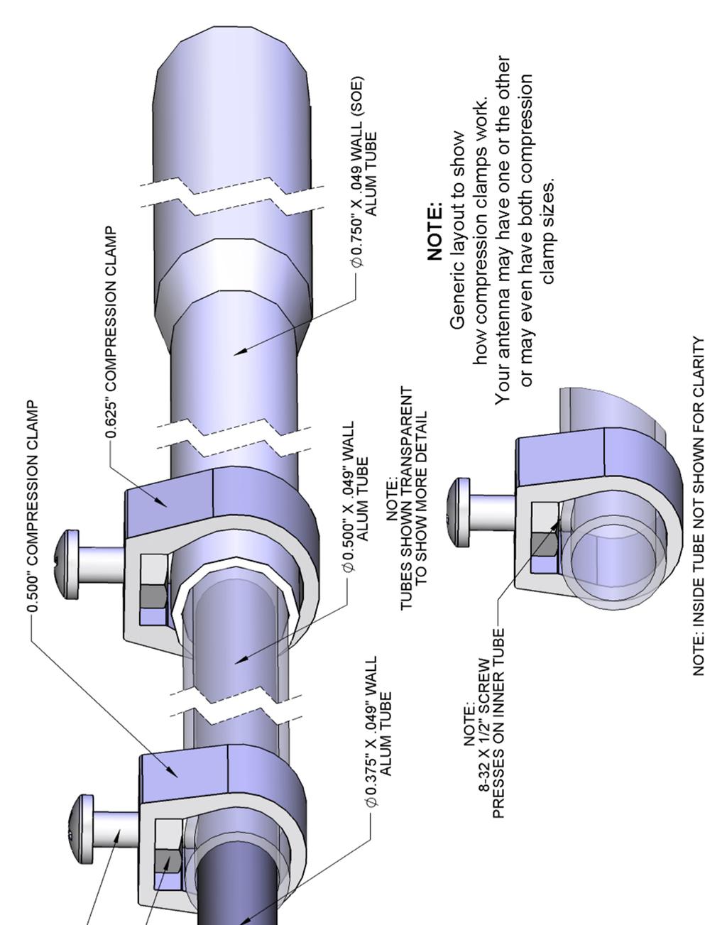

10 GENERIC COMPRESSION CLAMP DETAIL
11 KT31WARC TUNING NOTES Tuning The antenna concept is fairly straight forward. The 8 capacitor tube and the coil create a trap for 12M and passes the lower frequencies, the 10 capacitor tube along with the linear loading tunes 17M. 30M and 20M runs through all the linear loading to final longest tip. This antenna when close to the ground will have an effect of lowering all the bands in frequency. As the antenna is raised the frequency on all bands will raise slightly as the antenna reaches around 30 ft, as the antenna is raised higher any changes will be minor. You may find that the lowest SWR point for each band may very. Several factors affect tuning, including height above ground, adjacent structures, and other nearby antennas. All tip measurements given are based on a height of 30 FT. If tuning is needed; start by tuning from the highest band and work your way down in frequency. Refer to the element layout option page to see the differences of the antenna dimensions for 30M or 20M. The 12M band is tuned by the position of the 3/8 x 1 x 3/8 shorting bar, the 30 dimension is given as a starting point. All the bands run through this shorting bar, so the other bands will be affected by the position of this shorting bar, so do not be alarmed if the others bands change as you change this shorting bar position for 12M. If you want the antenna to work lower in frequency, increase the 30 dimension in 1/2 inch increments, testing at least 30 above ground or optimally in final position. After the antenna is tuned where you want it in the 12M band then move on to the 17M band. The 17M band is tuned by the 1/2 x 9 tip that slides over the 3/8 x 48 tube that is exposed 4. Standard tuning concepts applies, shortening the tip raises this band in frequency, lengthening the tip lowers the band in frequency. Finally tune the chosen low band 20M or 30M. The 30M and 20M bands are tuned by the amount of the longest tips. Refer to the element layout option page to see the differences of the antenna dimensions for 30M or 20M. Remember it is always a good idea to make small changes, 1/2 increments, then test at least 30 ft. above ground or optimally in final position. M 2 ANTENNA SYSTEMS, INC N. Selland Ave. Fresno, CA (559) Fax: sales@m2inc.com
12 KT31WARC PARTS & HARDWARE DESCRIPTION... QTY ELEMENT SEC, 1 1/4X.058 X SOE... 2 SLEEVE SEC, 1 1/8X.058 X SLEEVE SEC, 1.0X.058 X ELEMENT SEC, 1 X.058 X SOE... 2 ELEMENT, 3/4 X.049 X WARC COIL ASSEMBLY... 2 CAPACITOR TUBE, 3/4 X CAPACITOR TUBE, 3/4 X ELEMENT, 1/2 X.049 X T MATCH TUBE, 1/2 X.049 X ELEMENT TIP, 17M, 1/2 X.049 X LL ELEMENT, 3/8 X.049 X W VENT HOLES... 2 ELEMENT TIP, 3/8 X.049 X FIBERGLASS INSULATOR, 7/8 X 14-3/4 (M2AFG0030)... 1 FIBERGLASS INSULATOR, 5/8 X 6 (M2AFG0029)... 2 FIBERGLASS INSULATOR, 3/8 X (M2AFG0010)... 1 CAPACITOR CAPS, 3/8 TO 3/4 (M2APL0019)... 8 SB INSULATOR, (M2ASB0053)... 2 SHORT BAR, 3/8 X 1.0 X 3/8 (M2ASB0052)... 2 SHORT BAR, 3/4 X 1.0 X 3/4 (M2ASB0050)... 2 SHORT BAR, 3/4 X 3/8 (M2ASB0057)... 2 T MATCH SHORT BAR, 1 1/4 X 1/2 (M2ASB0059)... 2 BALUN, 1: MHZ, 3 KW (FGBL0700)... 1 BALUN MOUNT PLATE, 2 X 4 X 1/8 (M2APT0018)... 1 BOOM TO MAST PLATE, 4 X 6 X 3/16 (M2APT0225)... 1 UNICRADLE (M2AMC0076)... 2 COMPRESSION CLAMP, 5/ COMPRESSION CLAMP, 1/ U-BOLT, STAINLESS STEEL /2 U-BOLT & CRADLE... 1 ZINC PASTE, SMALL... 1 ASSEMBLY MANUAL... 1 HARDWARE: WASHER, 5/16 SPLIT RING, SS... 2 NUT, 5/16-18, SS... 2 BOLT, 1/4-20 X 1-3/4, SS... 2 BOLT, 1/4-20 X 1-1/2, SS... 2 WASHER, 1/4 SPLIT RING, SS... 6 NUT, 1/4-20, SS... 8 LOCKNUT, 1/4-20, SS... 4 SCREW, 8-32 X 1-3/4 PAN HEAD PHL, SS... 2 SCREW, 8-32 X 1-1/2 PAN HEAD PHL, SS... 4 SCREW, 8-32 X 1-1/4 PAN HEAD PHL, SS SCREW, 8-32 X 1.0 PAN HEAD PHL, SS SCREW, 8-32 X 7/8 PAN HEAD PHL, SS... 8 SCREW, 8-32 X 1/2 PAN HEAD PHL, SS... 6 NUT, 8-32, SS... 8 LOCKNUT, 8-32, SS RING LUG, #8 HOLE #10 WIRE... 2 COIL ASSEMBLIES (2) (PRE-ASSEMBLED) ELEMENT SECTION, 3/4 X.049 X 10 SOE... 2 ELEMENT SECTION, 3/4 X.049 X COIL, 7.5 TURN... 2 COIL INSULATOR (M2AFG0028)... 2 COIL POST (M2ACP000)... 4 COIL COVER, UHMW 3.420X CAP, COVER,3/4 HOLE... 4 SHORT BAR, (M2ASB0051)... 2 SCREW, 8-32 X 1 SS... 8 LOCK NUT, 8-32 SS... 4 SET SCREW, 1/4-20 X 1/4 SS... 4
M2 Antenna Systems, Inc. Model No: 20M6-125
 M2 Antenna Systems, Inc. Model No: 20M6-125 SPECIFICATIONS: Model... 20M6-125 Frequency Range... 14.0 14.350 MHz *Gain, (FS) / Over gnd... 11.19dBi / 16.6dBi @70 Front to back... 25 db Typical Beamwidth...
M2 Antenna Systems, Inc. Model No: 2M4
 M2 Antenna Systems, Inc. Model No: 2M4 SPECIFICATIONS: Model... 2M4 Frequency Range... 144 To 148 MHz *Gain... 9.6 dbi Front to back... 20 db Typical Beamwidth... E=54 H=74 Feed type... T Match Feed Impedance....
M2 Antenna Systems, Inc. Model No: 2M7
 M2 Antenna Systems, Inc. Model No: 2M7 SPECIFICATIONS: Model... 2M7 Frequency Range... 144 To 148 MHz *Gain... 12.3 dbi Front to back... 20 db Typical Beamwidth... E=43 H=50 Feed type... T Match Feed Impedance....
M2 Antenna Systems, Inc. Model No: 20M5LD
 M2 Antenna Systems, Inc. Model No: 20M5LD SPECIFICATIONS: Model... 20M5LD Frequency Range... 14.0 14.350 MHz *Gain (Full Band)... 10.2 dbi Typical Front to back... 23 db Typical Beamwidth... E=50 / H=66
M2 Antenna Systems, Inc. Model No: 10-30LP8
 M2 Antenna Systems, Inc. Model No: 10-30LP8 SPECIFICATIONS: Model... 10-30LP8 Frequency Range... 10-30 MHz Continuous *Gain free space / 65... 5.2 dbi / 10.5 dbi 10-30 Front to back... 15 db 10-30 MHz
M2 Antenna Systems, Inc. Model No: 10-30LP8
 M2 Antenna Systems, Inc. Model No: 10-30LP8 VSWR 2:1 TYPICAL VSWR @ 70 FT. 2:1 1.5:1 1.5:1 1.2:1 1.2:1 10 14 MHz 11 12 13 17 15 16 18 19 20 21 22 23 24 25 26 27 28 29 30 SPECIFICATIONS: Model...10-30LP8
M2 Antenna Systems, Inc. Model No: 450CP34
 M2 Antenna Systems, Inc. Model No: 450CP34 SPECIFICATIONS: Model... 450CP34 Frequency Range... 435 To 455 mhz *Gain... 16.0 dbi Front to back... 22 db Typical Beamwidth... 28 Circular Feed type... T Match
M2 Antenna Systems, Inc. Model No: HFTB6MXP20-2X2
 M2 Antenna Systems, Inc. Model No: HFTB6MXP20-2X2 FRONT OF SYSTEM REAR OF SYSTEM SPECIFICATIONS: Model... HFTB6MXP20-2X2 Band... 6M Antenna... 6MXP20 T-Brace... Y Cross Boom Dia... 4.5 Wind Load w/o Ant.....
M2 Antenna Systems, Inc. Model No: 456CP34
 M2 Antenna Systems, Inc. Model No: 456CP34 SPECIFICATIONS: Model... 456CP34 Frequency Range... 435 To 470 mhz *Gain... 16.0 dbi Front to back... 23 db Typical Beamwidth... 30 Circular Feed type... T Match
M2 Antenna Systems, Inc. Model No: 10-30LP8-125
 M2 Antenna Systems, Inc. Model No: 10-30LP8-125 VSWR 2:1 TYPICAL VSWR @ 70 FT. 2:1 1.5:1 1.5:1 1.2:1 1.2:1 10 14 MHz 11 12 13 17 15 16 18 19 20 21 22 23 24 25 26 27 28 29 30 SPECIFICATIONS: Model...10-30LP8-125
M2 Antenna Systems, Inc. Model No: 40M3L
 M2 Antenna Systems, Inc. Model No: 40M3L SPECIFICATIONS: Model... 40M3L Frequency Range... 7.0-7.3 MHz X 150 khz Gain... 6.6 dbi Front to back... 23 db Beamwidth... E=62 Feed type... Hair pin match Feed
M2 Antenna Systems, Inc. Model No: 436CP30
 M2 Antenna Systems, Inc. Model No: 436CP30 SPECIFICATIONS: Model... 436CP30 Frequency Range... 432 To 440 MHz *Gain... 15.50 dbic Front to back... 18 db Typical Elipticity... 1.5 db Typical Beamwidth...
M2 Antenna Systems, Inc. Model No: 450CP26
 M2 Antenna Systems, Inc. Model No: 450CP26 SPECIFICATIONS: Model... 450CP26 Frequency Range... 445 To 455 mhz *Gain... 16.5 dbi Front to back... 21 db Typical Beamwidth... 30 Circular Feed type... T Match
M2 Antenna Systems, Inc. Model No: YAGI ANTENNA
 M Antenna Systems, Inc. Model No: 4.5-7 YAGI ANTENNA SPECIFICATIONS: Model... 4.5-7 Frequency Range... 4.0 To 4.5 MHz *Gain... 0 To 7 dbi Front to back... 0 db over the rear 80 Beamwidth... E=44 H=50 typical
M2 Antenna Systems, Inc. Model No: 2MCP22
 M2 Antenna Systems, Inc. Model No: 2MCP22 SPECIFICATIONS: Model... 2MCP22 Frequency Range... 144 To 148 MHz *Gain... 14.39 dbic Front to back... 25 db Typical Elipticity... >3db Beamwidth... 38 Feed type...
THIS SHOULD TWEAK YOUR IMAGINATION
 10-27-05 THIS SHOULD TWEAK YOUR IMAGINATION SPECIFICATIONS FOR SINGLE ANTENNA MODEL NUMBER... 432EME-12 FREQUENCY... 430-436 MHz GAIN... 14.4 dbd FRONT TO BACK... 23 db VSWR... 1.2:1 TYPICAL BEAMWIDTH...
M2 Antenna Systems, Inc. Model No: 2M5WL
 M2 Antenna Systems, Inc. Model No: 2M5WL SPECIFICATIONS: Model... 2M5WL Frequency Range... 144 To 148 MHz *Gain... 16.84 dbi Front to back... 22 db Typical Beamwidth... E=26 H=29 Feed type... T Match Feed
M2 Antenna Systems, Inc. Model No: HFTB2MXP X2-3K
 M2 Antenna Systems, Inc. Model No: HFTB2MXP28-32-2X2-3K FRONT OF SYSTEM REAR OF SYSTEM SPECIFICATIONS: Model... HFTB2MXP28-32-2X2-3K Band... 2M Antenna... 2MXP28-32 T-Brace... Y Cross Boom Dia... 3.0 Wind
M2 Antenna Systems, Inc. Model No: HFTB2MXP X2-1K
 M2 Antenna Systems, Inc. Model No: HFTB2MXP28-32-2X2-1K FRONT OF SYSTEM REAR OF SYSTEM SPECIFICATIONS: Model... HFTB2MXP28-32-2X2-1K Band... 2M Antenna... 2MXP28-32 T-Brace... Y Cross Boom Dia... 3.0 Wind
M2 Antenna Systems, Inc. Model No: 40M2L
 M2 Antenna Systems, Inc. Model No: 40M2L SPECIFICATIONS: Model...40M2L Frequency Range...6.9-10 MHz X 150 khz Gain...5.5 dbi Front to back...13 15 db Beamwidth...E=74 Feed type...hair pin match Feed Impedance....50
M2 Antenna Systems, Inc. Model No: 6M8GJ
 M2 Antenna Systems, Inc. Model No: 6M8GJ SPECIFICATIONS: Model... 6M8GJ Frequency Range... 50.0 To 50.4 mhz *Gain, (FS) / Over gnd... 14.2 dbi / 19 dbi @ 20 Front to back... 20 db Typical Beamwidth...
M2 Antenna Systems, Inc. Model No: 7&10-30LP8
 M2 Antenna Systems, Inc. Model No: 7&10-30LP8 2:1 100KHz BANDWIDTH@ 1.8:1 VSWR 1.5:1 6.9 7.0 7.1 10 FREQUENCY (MHZ) 20 SPECIFICATIONS: Model...7&10-30LP8 Skip log Frequency Range...10-30 MHz Continuous
M2 Antenna Systems, Inc. Model No: FGHFTB2MXP202X2
 M2 Antenna Systems, Inc. Model No: FGHFTB2MXP202X2 FRONT OF SYSTEM REAR OF SYSTEM SPECIFICATIONS: Model... HFTB2MXP20-2X2 Band... 2M Antenna... 2MXP20 T-Brace... Y Cross Boom Dia... 3.0 Wind Load w/o Ant.....
M2 Antenna Systems, Inc. Model No: 2M HO LOOP
 M2 Antenna Systems, Inc. Model No: 2M HO LOOP SPECIFICATIONS: Model... 2M HO LOOP Frequency Range... 144 To 144.5 MHz Gain, Typical @ 10 ft.... 4 dbd @ 10 deg. Gain, 2 STK @ 82 & 132... 8 dbd @ 9 deg.
M2 Antenna Systems, Inc. Model No: 435XP50
 M2 Antenna Systems, Inc. Model No: 435XP50 SPECIFICATIONS: Model... 435XP50 Frequency Range... 430 To 436 MHz *Gain... 19.2 dbi Front to back... 22 db Typical Cross pol. isolation... >20 db Typical Beamwidth...
M2 Antenna Systems, Inc. Model No:
 M2 Antenna Systems, Inc. Model No: 400-600-10 SPECIFICATIONS: Model... 400-600-10 Frequency Range... 390 To 650 MHz *Gain... 12 To 13 dbic Front to back... 20 db Nominal Beamwidth... 46 Nominal Feed Impedance....
Directive Systems & Engineering 2702 Rodgers Terrace Haymarket, VA
 Directive Systems & Engineering 2702 Rodgers Terrace Haymarket, VA 20169 1628 www.directivesystems.com 703 754 3876 K1JX DESIGNED 6 ELEMENT 50 MHZ YAGI, DSEJX6 50 INTRODUCTION The Directive Systems DSEJX6-50
M2 Antenna Systems, Inc. Model No: KT34XA TO KT36XA UPGRADE KIT
 M2 Antenna Systems, Inc. Model No: KT34XA TO KT36XA UPGRADE KIT SPECIFICATIONS: SPECIFICATIONS for the KT34-6XA MODEL NUMBER...KT36XA FREQ. RANGE...14.0-14.35 MHz 21.0-21.45 MHz 28.0-29.0 MHz GAIN (Free
K1FO 12 ELEMENT 144/147 MHz YAGI
 K1FO 12 ELEMENT 144/147 MHz YAGI WARNING: INSTALLATION OF THIS PRODUCT NEAR POWER LINES IS DANGEROUS. FOR YOUR SAFETY FOLLOW THE INSTALLATION DIRECTIONS. Ariane Arrays, Inc. Copyright 2006 201 Hopedale
TZ-RD-1740 Rotary Dipole Instruction Manual
 TZ-RD-1740 17/40m Rotary Dipole Instruction Manual The TZ-RD-1740 is a loaded dipole antenna for the 40m band and a full size rotary dipole for the 17m band. The antenna uses an aluminium radiating section
Assembly Instructions: Bencher Skylark
 Assembly Instructions: Bencher Skylark Tools Required: Pop Rivet Tool Tape Measure Hex Wrenches Screwdriver Several Disposable Rags Two Saw Horses Several boxes or bowls to hold fasteners and small parts
JK-65 Five Element 6M Yagi
 JK-65 Five Element 6M Yagi PO Box 266, Croton Falls, NY 10519-0266 845.228.8700 (TEL) 845.279.5526 (FAX) info@jkantennas.com Page 1 of 8 JK Antennas Limited Warranty and Liability JK Antennas ( Manufacturer
MI: (Secure this number someplace, for possible future need) SPECIFICATIONS:
 SPECIFICATIONS:") 6C ASSEMBLY INSTRUCTIONS ANTENNA MODEL T6 MI: 030927 (Secure this number someplace, for possible future need) SPECIFICATIONS: FORWARD GAIN 5.1 dbd F:B RATIO 15-25 db (Rises with frequency) FREQUENCY COVERAGE
6C ASSEMBLY INSTRUCTIONS ANTENNA MODEL T6 MI: 030927 (Secure this number someplace, for possible future need) SPECIFICATIONS: FORWARD GAIN 5.1 dbd F:B RATIO 15-25 db (Rises with frequency) FREQUENCY COVERAGE
INSTRUCTION MANUAL. Specifications Mechanical. 1 5/8 to 2 1/16 O.D. (41mm to 52mm)
") 308 Industrial Park Road Starkville, MS 39759 USA Ph: (662) 323-9538 FAX: (662) 323- General Description Model VB-25FM 2-Meter 5 Elements Beam INSTRUCTION MANUAL This antenna is a 5-element, 2-meter beam
308 Industrial Park Road Starkville, MS 39759 USA Ph: (662) 323-9538 FAX: (662) 323- General Description Model VB-25FM 2-Meter 5 Elements Beam INSTRUCTION MANUAL This antenna is a 5-element, 2-meter beam
Cushcraft. Amateur Radio Antennas DB-46M8EL. Dual band 6 and 4 Meter, 8 Element Beam Antenna INSTRUCTION MANUAL
 Cushcraft Amateur Radio Antennas DB-46M8EL Dual band 6 and 4 Meter, 8 Element Beam Antenna INSTRUCTION MANUAL CAUTION: Read All Instructions Before Operating Equipment VERSION 1B Cushcraft Amateur Radio
Model VB-23FM 2-Meter 3-Element Beam
 308 Industrial Park Road Starkville, MS 39759 USA Ph: (662) 323-9538 FAX: (662) Model VB-23FM 2-Meter 3-Element Beam [ INSTRUCTION MANUAL Figure 1 Overall View and Boom Detail GENERAL DESCRIPTION This
CP6 6 Band Trap Vertical 80-6m
 CP6 6 Band Trap Vertical 80-6m Instruction Sheet The CP6 is a multi-band trap-vertical antenna for HF bands, covering the 80*, 40, 20, 15, 10m & 6m amateur bands. Made from heavy duty aluminum, the CP6
INSTRUCTION MANUAL. Specifications Electrical. Front-To-Back Ratio VSWR at Resonance Less than 1.5:1 Nominal Impedance. Mechanical
 300 Industrial Park Road, Starkville, MS 39759 Ph: (662) 323-8538 FAX: (662) 323-6551 TH-3JRS Tri-band HF 3 Elements Beam Covers 10, 15 and 20 Meters INSTRUCTION MANUAL WARNING Installation of this product
JK M Hi-Q Coil Loaded Rotatable Dipole Version
 JK-401 40M Hi-Q Coil Loaded Rotatable Dipole 2018 Version 72 Grays Bridge Road, Unit D, Brookfield, CT 06804 845.228.8700 (TEL) 845.279.5526 (FAX) info@jkantennas.com LAST UPDATED: 02-01-2018 JK Antennas
MOUNTING INSTRUCTIONS
 Standard Mounting Bracket Tilting Bracket* Mounting example Right side for upper tilt from 0 to 20 20 Spare parts: p/n SA197 Materials: extruded aluminum Hardware: stainless & zinc plated steel Dimensions
PACKING LIST MACO V-5000
 PACKING LIST MACO V-5000 PART QTY O.D. SIZE LENGTH DESCRIPTION CHECKLIST T47P 4 5/8.050 36 Aluminum Tubing _ T43P 1 7/8.050 48 Aluminum Tubing _ T18P 1 3/4.050 48 Aluminum Tubing _ T15P 1 5/8.050 48 Aluminum
Build a 12/17 Meter Trap Dipole Phil Salas AD5X
 Build a 12/17 Meter Trap Dipole Phil Salas AD5X Introduction Why a 12/17 meter rotatable dipole? Well, many folks have verticals for the lower bands, and multi-band dipoles or beams for 20-, 15-, and 10
INSTRUCTION MANUAL. Model 18AVQII Five Band Vertical Antenna 10, 15, 20, 40, 80 Meter. General Description. Theory of Operation
 Model 18AVQII Five Band Vertical Antenna 10, 15, 20, 40, 80 Meter 308 Industrial Park Road Starkville, MS 39759 (662) 323-9538 Fax: (662) 323-5803 INSTRUCTION MANUAL General Description The Hy-Gain 18AVQII
HFp. User s Guide. Vertical. entenna. 7 MHz 30 MHz Amateur Radio Antenna Plus 6-Meters
 User s Guide HFp Vertical 7 MHz 30 MHz Amateur Radio Antenna Plus 6-Meters The Ventenna Co. LLC P.O. Box 2998, Citrus Heights, CA, 956 www.ventenna.com entenna Table of Contents The HFp Antenna -------------------------------------------------------------------
The W3FF Portable Dipole
 The W3FF Portable Dipole This is the antenna I designed for my 'walking portable' station. It is a dipole constructed out of the plastic plumbing pipe CPVC. There are telescoping whips at the ends of each
Assembly Instructions for the 10N6RDB Antenna
 Assembly Instructions for the 10N6RDB Antenna The 10N6RDB antenna comes from the factory almost completely assembled. All you have to do is install the 1/2 inch Aluminum tubing at both ends of the 10 Meter
Installation Instructions Hustler 6-BTV Trap Vertical
 Installation Instructions Hustler 6-BTV Trap Vertical ASSEMBLY 1. Check the package contents against the parts list on page 2. 2. WARNING. Installation of this product near power lines is dangerous. For
INSTRUCTION MANUAL. Model VB-215DX MECHANICAL DESIGN GENERAL DESCRIPTION ELECTRICAL DESIGN. 2 Meter 15 Element Yagi for SSB/CW
 Model VB-215DX 2 Meter 15 Element Yagi for SSB/CW INSTRUCTION MANUAL GENERAL DESCRIPTION The Hy-Gain Model 215DX is a high performance yagi antenna for SSB/CW DXing in the Amateur 2 meter band. It features
Pacific Antenna 20 and 40M Lightweight Dipole Kit
 Pacific Antenna 20 and 40M Lightweight Dipole Kit Antenna diagram showing configuration and lengths when assembled 7 8 16 9 16 9 Description The Pacific Antenna lightweight dual band dipole kit provides
CP6A. 6 Band Trap Vertical 75-6m
 CP6A 6 Band Trap Vertical 75-6m Instruction Sheet The CP6A is a multi-band trap-vertical antenna for HF bands, covering the 75*, 40, 20, 15, 10m & 6m amateur bands. Made from heavy duty aluminum, the CP6A
Directive Systems & Engineering 2702 Rodgers Terrace Haymarket, VA
 Directive Systems & Engineering 2702 Rodgers Terrace Haymarket, VA 20169-1628 www.directivesystems.com 703-754-3876 25 Element 7.4 wl. K1FO Designed Yagi, Model DSEFO432-25 ELECTRICAL SPECIFICATIONS Frequency
INSTRUCTION MANUAL V-42R. Dual Band Collinear Gain Vertical for MHz and GENERAL DESCRIPTION
 308 Industrial Park Road, Starkville, MS 39759 USA Ph: (662) 323-9538 FAX: (662) 323-6551 V-42R Dual Band Collinear Gain Vertical for 144-148 MHz and 436-450 INSTRUCTION MANUAL GENERAL DESCRIPTION The
Installation Instructions Hustler 6-BTV Trap Vertical
 Installation Instructions Hustler 6-BTV Trap Vertical ASSEMBLY 1. Check the package contents against the parts list on page 2. 2. WARNING. Installation of this product near power lines is dangerous. For
INSTRUCTION MANUAL for MODEL TH6-DX "THUNDERBIRD" (389)
") INSTRUCTION MANUAL for MODEL TH6-DX "THUNDERBIRD" (389) HY-GAIN ELECTRONICS CORPORATION, N. E. Hwy #6 at Stevens Creek, Lincoln, Nebraska 65801 Telephone 434-6331 INTRODUCTION Ely-Gain's new Model TH6-DX
INSTRUCTION MANUAL for MODEL TH6-DX "THUNDERBIRD" (389) HY-GAIN ELECTRONICS CORPORATION, N. E. Hwy #6 at Stevens Creek, Lincoln, Nebraska 65801 Telephone 434-6331 INTRODUCTION Ely-Gain's new Model TH6-DX
Cushcraft. Amateur Radio Antennas LFA-6M5EL. 6 Meter 5 Element Loop Feed Antenna INSTRUCTION MANUAL
 Cushcraft Amateur Radio Antennas LFA-6M5EL 6 Meter 5 Element Loop Feed Antenna INSTRUCTION MANUAL CAUTION: Read All Instructions Before Operating Equipment VERSION 1A Cushcraft Amateur Radio Antennas 308
JK-404 GRANDE Four Element Full Size 40M Yagi
 JK-404 GRANDE Four Element Full Size 40M Yagi PO Box 266, Croton Falls, NY 10519-0266 845.228.8700 (TEL) 845.279.5526 (FAX) info@jkantennas.com JK Antennas Limited Warranty and Liability JK Antennas (
GlideRite Retractable Cover System For Hot Spot Spas (SE & SLX only)
") List of Contents Quantity Description 12 #10 x 1 ½ Flat Head Phillips Screw (see pg. 2) 2 #10 x ½ Pan Head Phillips Screw (see pg. 2) 8 ¼ x 2 ½ Lag Bolt (see pg. 2) 7 ¼ 20 x 5 / 8 Hex Head Bolt (see pg.
List of Contents Quantity Description 12 #10 x 1 ½ Flat Head Phillips Screw (see pg. 2) 2 #10 x ½ Pan Head Phillips Screw (see pg. 2) 8 ¼ x 2 ½ Lag Bolt (see pg. 2) 7 ¼ 20 x 5 / 8 Hex Head Bolt (see pg.
Construction manual for 50 MHz XL design yagi-kits
 Construction manual for 50 MHz XL design yagi-kits Source: http://www.nuxcom.de/pdf/nuxcom_construction-manual_6m-xl.pdf Please check if all parts listed in the invoice are delivered with the kit. In the
TELEX, liutiiilio"i TELEX COMMUNICATIONS, INC ALDRICH AVE. SO. MINNEAPOLIS. MN USA
 TELEX, liutiiilio"i TELEX COMMUNICATIONS, INC. 9600 ALDRICH AVE. SO. MINNEAPOLIS. MN 55420 USA INSTRUCTION MANUAL ORDER NO. 410 General This antenna is a five-element, Citizens Band beam with a forward
C-3S, C-3S/D, C-3S/H, C3S/HH
 Strike Force Classic 3-Band C-3S, C-3S/D, C-3S/H, C3S/HH 20, 15 and 10 Meter (plus 17 & 12) Multi-monoband Yagi Antenna FREQUENCY COVERAGE: 13.950-14.400; 21.000-21.450; 1.1 MHz of 10 Meters (VSWR
GlideRite Retractable Cover System For HotSpring & Tiger River Spas (except Classic & pre-2000 Landmark Spas)
") List of Contents Quantity Description 12 #10 x 1 ½ Flat Head Phillips Screw (see pg. 2) 2 #10 x ½ Pan Head Phillips Screw (see pg. 2) 8 ¼ x 2 ½ Lag Bolt (see pg. 2) 7 ¼ 20 x 5 / 8 Hex Head Bolt (see pg.
List of Contents Quantity Description 12 #10 x 1 ½ Flat Head Phillips Screw (see pg. 2) 2 #10 x ½ Pan Head Phillips Screw (see pg. 2) 8 ¼ x 2 ½ Lag Bolt (see pg. 2) 7 ¼ 20 x 5 / 8 Hex Head Bolt (see pg.
MODEL DB-1015A 10- and 15-Meter Duo-Band Antenna Order No. 330
 MODEL DB-1015A 10- and 15-Meter Duo-Band Antenna Order No. 330 HY-GAIN ELECTRONICS CORPORATION 8601 Northeast Highway 6 Lincoln, Nebraska 68505 Telephone 464-9151 Area Code 402 TABLE OF CONTENTS page SECTION
TW4040. The Adventurer Monobander INSTRUCTION MANUAL. TransWorld Antennas
 TW4040 The Adventurer Monobander TransWorld Antennas INSTRUCTION MANUAL Contents 1 Limited Warranty 3 2 Important Safety Information 4 3 Specifications 3.1 Mechanical 4 3.2 Electrical 4 3.3 VSWR Performance
LJ element beam for 10 or 12 meters INSTRUCTION MANUAL. CAUTION: Read All Instructions Before Operating Equipment
 LJ-113 3 element beam for 10 or 1 meters INSTRUCTION MANUAL CAUTION: Read All Instructions Before Operating Equipment 308 Industrial Park Road Starkville, MS 39759 USA Tel: 66-33-9538 Fax: 66-33-6551 VERSION
PAC-12 Kit Contents. Tools Needed Soldering iron Phillips screwdriver Wire stripper Wrenches, 7/16 and 1/2 Terminal crimp tool Pliers Solder
 PAC-2 Kit Contents Part Quantity Screws: 8/32 x 3/8 Screws: 8-32 x 5/6 Screw: 8-32 x /4 #8 internal tooth washers #8 solder lug ring terminals Bolt: Aluminum, /4-20 x.5 /4 internal tooth washer Nut: Aluminum
Pacific Antenna 20 and 40M Lightweight Dipole Kit
 Pacific Antenna 20 and 40M Lightweight Dipole Kit Diagram showing configuration and approximate lengths 8 3 16 9 16 9 8 3 Description The Pacific Antenna lightweight dual band, trap dipole kit provides
INSTRUCTION MANUAL. Model 18AVQII Five Band Vertical Antenna 10, 15, 20, 40, 80 Meter
 Model 18AVQII Five Band Vertical Antenna 10, 15, 20, 40, 80 Meter 308 Industrial Park Road Starkville, MS 39759 (662) 323-9538 Fax: (662) 323-5803 INSTRUCTION MANUAL General Description The Hy-Gain 18AVQII
JK NAVASSA-5. 5-Band Yagi (20M/17M/15M/12M/10M) Optional 6M Add-on Kit Available
 Optional 6M Add-on Kit Available") JK NAVASSA-5 5-Band Yagi (20M/17M/15M/12M/10M) Optional 6M Add-on Kit Available 72 Grays Bridge Road, Unit D, Brookfield, CT 06804 845.228.8700 (TEL) 845.279.5526 (FAX) info@jkantennas.com Last Updated:
JK NAVASSA-5 5-Band Yagi (20M/17M/15M/12M/10M) Optional 6M Add-on Kit Available 72 Grays Bridge Road, Unit D, Brookfield, CT 06804 845.228.8700 (TEL) 845.279.5526 (FAX) info@jkantennas.com Last Updated:
TENNADYNE. Aluminum with a PhD. Tennadyne ASSEMBLY INSTRUCTIONS MODEL: T Log Periodic Antennas SPECIFICATIONS:
 TENNADYNE Aluminum with a PhD ASSEMBLY INSTRUCTIONS MODEL: T10-100224 SPECIFICATIONS: FREQUENCY COVERAGE 13-33 MHz FORWARD GAIN 6.1 dbd ½ POWER BEAMWIDTH 52 DEGREES F:B RATIO To 25 Db (Rises with frequency)
HFp. User s Guide. Vertical. entenna. 7 MHz 54 MHz Amateur Radio Antenna. The Ventenna Co. LLC P.O. Box 227 Huston, ID
 User s Guide HFp Vertical 7 MHz 54 MHz Amateur Radio Antenna The Ventenna Co. LLC P.O. Box 227 Huston, ID 83630 www.ventenna.com entenna Table of Contents The HFp Antenna -------------------------------------------------------------------
W6NL Moxon on Cushcraft XM240
 W6NL Moxon on Cushcraft XM240 0 db = 10.73 dbi 7.050 MHz 2.00 99.5% Efficiency High F/B 300+ khz VSWR BW SWR 1.50 1.00 7 7.1 7.2 7.3 MHz - 1 - Construction of W6NL Moxon on Cushcraft XM240 Dave Leeson,
2 Element Yagi Instruction Manual
 2 Element Yagi Instruction Manual 3Y0X Peter 1 DXpedition 2006 Manual REV 3.0 September 2012 2112 116TH AVE NE SUITE 1-5, BELLEVUE WA, 98004 WWW.STEPPIR.COM TEL: (425)-453-1910 FAX: (425)-462-4415 SteppIR
Spiderbeam Balun Construction Guide
 BALUN CONSTRUCTION GUIDE Ver. 1.0 1 The components of the Balun Kit are in a plastic bag. Most of the components are inside the plastic case of the balun. The aluminum U-profile and the RG-142 Teflon Coax
MFJ-2982 Feather-Lite 80-6 Meter Vertical Antenna
 MFJ-2982 Feather-Lite 80-6 Meter Vertical Introduction: The MFJ-2982 is a lightweight 31-foot fiberglass antenna designed to mount on any convenient post, mast, or a suitable wide-stance tripod such as
Thor Audi A4/S4 Skid Plate Installation Instructions
 Thor Audi A4/S4 Skid Plate Installation Instructions Parts List: 1 Aluminum Skid Plate 2 Aluminum Side Wings 10 10mm Flat Washers 3 8mm Flat Washers 3 8mm Speed Clips 2 10x40mm Bolts 3 8x35mm Bolts 2 Rivet-nuts
Calf-Tel Pen System Assembly Instructions
 Calf-Tel Pen System Assembly Instructions (Instructions work for 4, 6, and the 7 Pen Systems) 1 ASSEMBLY OF PEN FRONT AND WALLS START THE ASSEMBLY BY LINING UP THE TWO UNI-DIRECTIONAL ARROWS IN THE TOP,
N5PUV s 4 Band Fan Dipole Experiment. Using the New SRI (Stanford Research Institute) Method
 Method") N5PUV s 4 Band Fan Dipole Experiment Using the New SRI (Stanford Research Institute) Method Goals of Experiment Develop a Multi-band Antenna that does NOT require a tuner Build using the new, easier tuning
N5PUV s 4 Band Fan Dipole Experiment Using the New SRI (Stanford Research Institute) Method Goals of Experiment Develop a Multi-band Antenna that does NOT require a tuner Build using the new, easier tuning
REP Design LLC. 193 Winding Ridge Rd, Southington, CT INSTALLATION INSTRUCTIONS:
 REP Design LLC 193 Winding Ridge Rd, Southington, CT 06489 1-860.426.1894 n7emw@cox.net www.repdesign.us INSTALLATION INSTRUCTIONS: SHD-SO239 Super Heavy Duty SO-239Antenna Mounting System Thank you for
MAG-CONV Basic, 48, 48R & Midline Front Mount
 Parts Required: Tools Used: Mag Wheels Brakes Brake Rods Mounting Bracket Anti Tippers 7/16" Wrench Screw Driver Rubber Mallet 5/8 Wrench 5mm Allen Wrench Step Execution Figures 1 Remove front 5" total
MFJ-2100 INSTRUCTION MANUAL. CAUTION: Read All Instructions Before Operating Equipment
 MFJ-2100 INSTRUCTION MANUAL CAUTION: Read All Instructions Before Operating Equipment 300 Industrial Park Road Starkville, MS 39759 USA Tel: 662-323-5869 Fax: 662-323-6551 COPYRIGHT C 2015 MFJ Enterprises
Pacific Antenna 20 and 40M Lightweight Dipole Kit
 Pacific Antenna 20 and 40M Lightweight Dipole Kit Diagram showing configuration and approximate lengths 8 6 16 9 16 9 8 6 Description The Pacific Antenna lightweight dual band, trap dipole kit provides
JK BigTri. 3-Band Yagi (20M/15M/10M) 36Ft Boom
 36Ft Boom") JK BigTri 3-Band Yagi (20M/15M/10M) 36Ft Boom 72 Grays Bridge Road, Unit D, Brookfield, CT 06804 845.228.8700 (TEL) 845.279.5526 (FAX) info@jkantennas.com UPDATED : FEB 2017 JK Antennas Limited Warranty
JK BigTri 3-Band Yagi (20M/15M/10M) 36Ft Boom 72 Grays Bridge Road, Unit D, Brookfield, CT 06804 845.228.8700 (TEL) 845.279.5526 (FAX) info@jkantennas.com UPDATED : FEB 2017 JK Antennas Limited Warranty
INSTALLING INVISIRAIL GLASS PANELS POST INFORMATION... 2 PRE-INSTALLATION... 2
 Contents POST INFORMATION... 2 PRE-INSTALLATION... 2 STEP A1: MEASURING FOR INVISIRAIL CUSTOM GLASS PANELS (skip if using Standard Sized Panels)... 2 STEP A2: GATHER ADDITIONAL TOOLS/SUPPLIES... 2 STEP
THE W3FF HOMEBREW BUDDIPOLE
 THE W3FF HOMEBREW BUDDIPOLE A PORTABLE ANTENNA DESIGN FOR AMATEUR RADIO History of the Buddipole In January of 2000, I began experimenting with a walking portable ham station. Since then, thousands of
Model CR 146/440. ArrowAntennas.com Simply the Best. Corner Reflector for 146 & 440 MHz. (307)
") 911 E. Fox Farm Rd. #2 Cheyenne, WY 82007 ArrowAntennas.com Simply the Best (307) 222-4712 info@arrowantennas.com Corner Reflector for 146 & 440 MHz Guarantee No hassle refund If you are not completely
911 E. Fox Farm Rd. #2 Cheyenne, WY 82007 ArrowAntennas.com Simply the Best (307) 222-4712 info@arrowantennas.com Corner Reflector for 146 & 440 MHz Guarantee No hassle refund If you are not completely
Model CR146. ArrowAntennas.com Simply the Best. Corner Reflector for 146 MHz. (307)
") 911 E. Fox Farm Rd. #2 Cheyenne, WY 82007 ArrowAntennas.com Simply the Best (307) 222-4712 info@arrowantennas.com Corner Reflector for 146 MHz Guarantee No hassle refund If you are not completely satisfied
911 E. Fox Farm Rd. #2 Cheyenne, WY 82007 ArrowAntennas.com Simply the Best (307) 222-4712 info@arrowantennas.com Corner Reflector for 146 MHz Guarantee No hassle refund If you are not completely satisfied
Slide the stock rubber tank mount caps onto the ends of the CS-1 tank mount:
 RYCA CS-1 BODY PARTS INSTALLATION GUIDE [The CS-1 installation guides should be used as supplements to the videos found on our Youtube Channel. There is no strict order to the build process, but it is
ALWAYS ATTACH THE SAFETY ROPE TO A STABLE SUPPORT BEFORE ATTEMPTING TO ATTACH THE UNIVERSAL MOUNT TO A WINDOW FRAME OR RAIL.
 MFJ-1622 Introduction The MFJ-1622 Antenna was designed to provide portable or permanent HF communications on 40 through 10 meters and VHF on 6 and 2 meters. The universal mount design allows the user
DB Duo-Monoband Beam 7 - Element, 12 and 17 Meter INSTRUCTION MANUAL. General Description
 308 Industrial Park Road Starkville, MS 39759 USA Ph: (662) 323-9538 FAX: (662) 323-6551 DB- 1217 Duo-Monoband Beam 7 - Element, 12 and 17 Meter INSTRUCTION MANUAL General Description The Hy-Gain DB-1217
Football Goal Posts MODEL SERIES: FGP400 and FGP600 series
 Football Goal Posts MODEL SERIES: FGP400 and FGP600 series Installation and Maintenance Instructions Please read all instructions before attempting installation of these units SAVE THESE INSTRUCTIONS FOR
INSTALLATION INSTRUCTIONS
 AUTOMOTIVE PRODUCTS, INSTALLATION INSTRUCTIONS PLATINUM 4 OVAL STEP BAR (90 BENT END) APPLICATION: 2010-2015 Dodge Ram 2500/3500 Mega Cab PART NUMBER: 21-3570, 21-3575, 23-3570, 23-3575, 25-3570, 25-3575,
ASSEMBLY AND INSTALLATION INSTRUCTIONS R , 12, 15, 17, 20, 30, 40 Meters (5/99) COMMUNICATIONS ANTENNAS
 COMMUNICATIONS ANTENNAS") ASSEMBLY AND INSTALLATION INSTRUCTIONS R7000 10, 12, 15, 17, 20, 30, 40 Meters COMMUNICATIONS ANTENNAS 951465 (5/99) WARNING THIS ANTENNA IS AN ELECTRICAL CONDUCTOR. CONTACT WITH POWER LINES CAN RESULT
ASSEMBLY AND INSTALLATION INSTRUCTIONS R7000 10, 12, 15, 17, 20, 30, 40 Meters COMMUNICATIONS ANTENNAS 951465 (5/99) WARNING THIS ANTENNA IS AN ELECTRICAL CONDUCTOR. CONTACT WITH POWER LINES CAN RESULT
This manual will aid in the assembly of the FireBall V90 and FireBall X90. The assembly of both machines will be identical, unless specified.
 This manual will aid in the assembly of the FireBall V90 and FireBall X90. The assembly of both machines will be identical, unless specified. Step #1 Lay all parts out to verify quantities. (2) 2 x 25-1/4
General Product Brochure
 General Product Brochure SteppIR Antennas 2112 116th Ave NE #1-5 Bellevue, WA 98004 Tel: 425.453.1910 sales@steppir.com www.steppir.com SteppIR - Why Compromise? The SteppIR antenna was conceived to solve
LIGHT BEAM ANTENNA MaxRange Antenna Series Assembly Instructions MaxRange Plus Digital / High Definition Television Antennas
 LIGHT BEAM ANTENNA MaxRange Antenna Series Assembly Instructions MaxRange Plus Digital / High Definition Television Antennas Assembly Instructions 1 MaxRange Plus Antenna These instructions will lead you
MA5B 20 / 17 / 15 / 12 / 10 Meter Beam Antenna
 ASSEMBLY AND INSTALLATION INSTRUCTIONS NE 20 / 17 / 15 / 12 / 10 Meter Beam Antenna 951485_GF_AB WARNING THIS ANTENNA IS AN ELECTRICAL CONDUCTOR. CONTACT WITH POWER LINES CAN RESULT IN DEATH, OR SERIOUS
WPS crew Doors Installation instructions
 WPS-132-133 crew Doors Installation instructions ORDER OF INSTALLATION FOR A COMPLETE ENCLOSURE OF A CREW WPS (Weather Protection System) IS AS FOLLOWS: 1. Heater 2. Rear Thresholds - Right Hand & Left
INSTRUCTION MANUAL ORDER NO. V3R MODEL V3R. Collinear Gain Vertical for MHz
 ORDER NO. V3R MODEL V3R Collinear Gain Vertical for 216-225 MHz INSTRUCTION MANUAL General Description The new Hy-Gain V3R VHF antenna is a collinear 5/8-wave omnidirectional vertical antenna for the 216-225
This file was downloaded from the website of G7SYW.
 This file was downloaded from the website of G7SYW http://www.g7syw.co.uk ASSEMBLY AND INSTALLATION INSTRUCTIONS Five-Band High-Performance Mini-Vertical Antenna 951495 (8/01) WARNING THIS ANTENNA IS AN
HFp. User s Guide. Vertical. entenna. 7 MHz 30 MHz Amateur Radio Antenna
 User s Guide HFp Vertical 7 MHz 30 MHz Amateur Radio Antenna The Ventenna Co. LLC P.O. Box 2998, Citrus Heights, CA, 95611 www.ventenna.com entenna Table of Contents The HFp Antenna -------------------------------------------------------------------