M2 Antenna Systems, Inc. Model No: 10-30LP8
|
|
|
- Jordan Dominic Moody
- 5 years ago
- Views:
Transcription


1 M2 Antenna Systems, Inc. Model No: 10-30LP8 SPECIFICATIONS: Model LP8 Frequency Range MHz Continuous *Gain free space / dbi / 10.5 dbi Front to back db MHz Beamwidth... E=70 Typical Feed Impedance Ohms Unbalanced Maximum VSWR :1 Input Connector... SO-239, Others avl. Power Handling... 3 Kw, Higher avl. Boom Length / Dia / 3.0 x.125 Wall Maximum Element Length Turning Radius: Mast Size... 2 to 3 Nom. Wind area / Survival Sq. Ft. / 100 MPH Weight / Ship Wt Lbs. / 125 Lbs. *Subtract 2.14 from dbi for dbd FEATURES: Twenty years of log periodic engineering and field experience have gone into the design of the 10-30LP8 HYBRID log periodic. The result is a rugged, versatile antenna with excellent performance over a 20 MHz bandwidth. It s designed for years of trouble free service, featuring machined, 1/2 thick element-to-boom clamps, massive solid fiberglass rod center insulators, stainless steel hardware, and elements sleeved to achieve at least the 100 MPH wind survival rating. A broadband 3000 Watt 4:1 ferrite balun is supplied. Maritime, Government, Commercial, MARS, Amateur Radio communications and Shortwave listening are among 10-30LP8 s many, many uses. For receive only, it works extremely well from 1 to 100 MHz. This log will survive many years of all Mother Nature has to offer and continue to provide top performance with minimal maintenance. Stack with the 6-10LP5 for complete, efficient coverage from 6 to 30 MHz. M2 Antenna Systems, Inc N. Selland Ave. Fresno, CA Tel: (559) Fax: (559) Web: M2 Antenna Systems Incorporated 11/06/14 Rev.02
2 10-30LP8 ASSEMBLY MANUAL BEFORE YOU BEGIN: Look over the DIMENSION SHEET, HARDWARE AND ELEMENT ASSEMBLY DRAWINGS to get familiar with the various parts of the log periodic. Tools handy for assembly process: screwdriver, 11/32, 7/16, 1/2, 9/16 and 5/8 spin-tites, end wrenches and/or sockets, measuring tape. A small container of zinc paste (Penetrox, Noalox, or equiv.) has been provided to enhance and maintain the quality of all electrical junctions on this antenna. Apply a thin coat wherever two pieces of aluminum come in contact or any other electrical connections are made. 1. DESCRIPTION OFTHE ELEMENT CLAMP PLATES. ALSO SEE HARDWARE DRAWINGS. Three types of clamp plates pairs are supplied to fit three diameters of fiberglass rod insulators found at the center of elements #1 through #7. Pair them up as follows: A. Two 3 x 6 x 1/2 plates, milled with a 5/8 radius channel, are for ELEMENT #1 (the rear linear loaded element) and clamp a 1-1/4" x 24" fiberglass rod. B. Four other 3 x 6 x 1/2 clamp plates, milled with a 1/2 radius channel, are for ELEMENTS #2 AND #3 and clamp 1 x 24 fiberglass rods. C. Elements #4 through #7 use a single 2-1/2 x 4 x 3/8 plate and a matching rectangular 1-3/4 x 4 x 1/4" clamp plate, and clamp 7/8 x 29-3/4 inch long fiberglass rods. (Elements #4, 5, 6, and 7 use a single bottom cradle each). D. The front director element mounts differently, using two clamp cradles as described in step Start by assembling the two 1-1/4 rod CLAMP PLATES together with 1/4-20 x 2-1/2" bolts to the six holes. Add the 1/4-20 locknuts finger tight. Slip in the 1-1/4 X 24" fiberglass rod and rotate until the element mounting holes are vertical. Center the rod and tighten the clamp hardware EVENLY, so the plates are parallel and the same amount of threads are showing through all the locknuts. 3. Assemble the clamp plates pairs of ELEMENTS #2 & #3 with SIX 1/4-20x2-1/2" bolts and locknuts and a 1 x 24 Fiberglass rod, each. The clamp plate pairs for next four elements (#5, 6, 7, 8) require FOUR 1/4-20x1-3/4" bolts and locknuts and a 7/8 x 29-3/4 Fiberglass rod. 4. Now slide a POLYETHYLENE DISC INSULATOR (1-1/4, 1 or 7/8 internal Dia.) onto each end of ALL the fiberglass rods and push them up against the clamp plates. 5. MOUNTING INNER ELEMENT TUBING SECTIONS TO ELEMENT CLAMP ASSEMBLIES #1 THROUGH #7. REFER TO DIMENSION SHEET AND HARDWARE ASSEMBLY DRAWINGS. A. Inner element tubing sections have 1/4 holes in their straight (butt) ends. Pair up by diameter. To prepare the inner element sections for the PHASING LINE CLAMP ASSEMBLIES, apply a little zinc oxide paste to the last inch of each element butt. Also apply a little paste to the channels in all the small PHASING LINE CLAMP PLATES and the larger PHASING LINE CLAMP BLOCKS. This paste inhibits corrosion and helps to assure a reliable, low loss joint for many years. B. Loosely assemble plates to blocks, channel to channel, with 1/4-20 x 1 FLATHEAD SCREWS AND LOCKNUTS. Loosely install an 8-32 screw and locknut through block clamp fingers using 8-32 x 1-1/2 screws for 1 clamps, 8-32 x 1-3/4 screws for 1-1/4 clamps and 8-32 x 2 screws for the 1-1/2 clamps. Install a PHASING LINE CLAMP BLOCK assembly onto the end of each element butt with small clamp plate oriented to element butt.
3 10-30LP8 ASSEMBLY MANUAL 6. A. On element #1, slide 1-3/8 x 24 sleeve over the 1-1/4 fiberglass rod end and align the 1/4 holes. Then add the 1-1/2 x 60 inner element section over the sleeve and rod, align the holes and add a 1/4-20 x 2 bolt and locknut. Tighten securely. Repeat for the other inner element half. B. Repeat for elements #2 and #3 using 1-1/8 x 24 sleeves on the fiberglass rods, 1-1/4 x 60 inner element sections, and 1/4-20 x 1-3/4 bolts and locknuts. C. Install the 1 x 60 inner element sections of elements #4 through #6 directly to the 7/8 fiberglass rod insulators with 1/4-20 x 1-3/4 bolts and locknuts. Set element / clamp assemblies aside for now. D. For Element #7 attach the 1 x 1 x 4 Balun L-Bracket to the top two holes on one of the element clamp plates using two 1/4-20 x 2 bolts. Insert to 1/4-20 x 1-3/4 bolts in the bottom two holes. Insert the remaining 7/8 x 29-3/4 Fiberglass rod and secure all 1/4-20 hardware. See the drawing HARDWARE ARRANGEMENT FOR ELEMENT #7. 7. BOOM ASSEMBLY (THREE SECTION BOOM) Inspect the drilled ends of the boom sections for any aluminum chips or dirt. Wipe out with a clean rag. The straight section is the CENTER boom section. Slide the sections with the necked down end (swage) into the straight section. Align the holes and add the 1/4-20 x 3-1/2" bolts and locknuts. Tighten securely until no lateral movement occurs in the joints. (TWO SECTION BOOM) Wipe off the swaged end of the rear boom section. Now slide the other 15 boom section over the swage. Align the holes and add the hardware. Once all the bolts are in, tighten the nuts until the boom sections firm up and no joint movement is felt when wiggling the boom. B. Install the 3/8 EYEBOLTS to the outer ends of the boom, securing with stainless 3/8-16 nuts and lock washers. Align the eyes parallel with the boom and tighten. 8. Orient the boom with the eyebolt eyes "up. The boom end with the eyebolt at 52 from end is the REAR. Using a tape measure and a marking pen or masking tape, place a mark 1/2 in from the rear of the boom. This will be where you position the back edge of the clamp plate for element #1. Now measure forward (6 6-3/4 ) from that mark and make another mark. Call this position element #2. Continue marking the locations of all the elements using the element spacing figures given on the Dimension Sheet. 9. Attach the Element #1 element / clamp assembly to the boom. For ease of installation, support the boom about 3 above ground, eyebolts "up." Loosely attach two BOTTOM CRADLES to the bottom of the clamp plates using the 1/4-20 x 2-3/4" hardware. Slip Element #1 over the rear of the boom, placing the back edge of the rear plate on your first 1 inch mark. With the eyebolt in the boom vertical, adjust the inner element sections to the horizontal and tighten the cradle bolts securely. 10. Mount the next element / clamp assemblies with 1 fiberglass rods in element position #2 and #3. First place the clamp plates on the boom at the mark and then add the two bottom cradles and 1/4-20 x 2-3/4" bolts. Align with the first element clamp and tighten gently. 11. Mount the clamp plates with the 7/8 inch diameter fiberglass rods, again positioning each clamp at the mark, aligning with the first element and tightening. These elements require only one cradle. 12. A. Now mount the DIRECTOR ELEMENT. Insert the 3/4 x 60 element sections into the 7/8 x 30" center tube, align the holes and drop through two 1/4-20 x 5" bolts. Install an inverted cradle onto the bolts and up against the 7/8" sleeve section. Place this assembly on the boom. Add the bottom cradle, locknuts, then align elements and tighten nuts.
4 10-30LP8 ASSEMBLY MANUAL 13. INSTALLING THE PHASING LINES. SEE DIMENSION SHEET & HARDWARE ASSEMBLY DRAWINGS A. Start with the shortest set between element #6 and #7. For each set, feed the phasing lines through a 3/4 x 3 DELRIN SPACER so that the spacer sits at the crossover point between the lines. Hold the spacer in place loosely around the boom with a large nylon tie but don't tighten it yet. Adjust phasing lines so that their bends are even and the lines run parallel to the boom. B. Apply a small amount of conductive paste to the rod ends and feed the #7 ends into the clamp block channels until 1/4 extends beyond clamp. Tighten the 1/4-20 x 1 flathead screws and locknuts on element #7. Then adjust the block assemblies flush to the disc insulators and tighten 8-32 clamp screws. Insert the other rod ends into the clamp block assemblies on element #6 but do not tighten. Continue to the next phasing line set between element #5 and #6. Apply paste and insert the ends into the clamp blocks at element #6 and NOW tighten the flathead screws and nylon tie. While installing the phase lines, you might find that some of them will extend 1-2 past their respective clamp blocks. This is OK. You can trim them back, in order to fit flush with the clamp block faces, if you desire. C. Continue in the same fashion tightening the hardware and nylon ties as you go. Note the phasing lines between elements #3 and #4, the bends in this set of phasing lines are offset, with the crossover point closer to element #3. The phasing lines between elements #2 and #3 are offset, with the crossover point closer to element #3. D. Attach the 16 turn COIL to element #1 1/4-20 x 1 screw studs before securing phasing lines. 14. MOUNTING THE 4:1 BROAD BAND BALUN. Secure the BALUN to the 1 x 1 x 4" BALUN L-BRACKET MOUNTING PLATE with a 2-1/2" U-bolt and cradle. DO NOT OVERTIGHTEN - BALUN HOUSING COULD BE DAMAGED! Position balun with the connector pointing towards the rear of the boom and leads easily reaching phasing line clamp block screw studs. Now remove the 1/4 inch nuts from the clamp block screws. Apply some zinc paste to the lugs on the balun leads and place over each screw stud. Replace the nuts and retighten. 15. Attach the BOOM TO MAST PLATE with the two large 3 inch U-bolts. Center it at the Delrin standoff between element #3 and #4. Reshape the phasing lines as needed to clear the plate by at least 1/ OVERHEAD BOOM SUPPORT SYSTEM. A. Attach one end of the 5/16" Dacron cord to the rear eyebolt using two turns around the eyebolt and a series of three half hitches or equivalent knots. Without cutting the cord do the same at the front eyebolt. Pull on the knots HARD to SET them and tape the excess cord back to main cord tightly with black vinyl electricians tape. Seal ends with heat or flame to prevent fraying. B. TEMPORARILY insert a 2 inch U-bolt through the turnbuckle plate and add two nuts so about 1/2 inch of the threads stick out. Insert this assembly through the top set of 2 U-bolt holes in the boom to mast plate from the boom side and add two more nuts. Open the two turnbuckles up until just a thread or two from each end protrudes inside the body of the turnbuckle. Hook the turnbuckles into the holes at the edge of the turnbuckle plate. Equalize the Dacron cord over the plate and cut it. Take two wraps of the cord through the eye of the rear turnbuckle, PULL the cord as tight as possible and make the knots as before. Repeat for the front cord section and turnbuckle. Cut off any excess over one foot long and again seal and tape the excess cord back to the main cord. C. Now DISASSEMBLE the U-bolt from the boom to mast plate. The guy assembly is now centered and ready to be raised up the mast and adjusted to level the boom during the final installation. The turnbuckle plate, installed loosely with a 2 U-bolt, can be raised up the mast until the boom is straight.
5 10-30LP8 ASSEMBLY MANUAL D. If practical, after the final assembly steps below and before installation, let the overhead guy system support the boom and take a set overnight: Install a 2 to 3 temporary 2 mast section to the boom to mast plate and attach and raise the turnbuckle plate. Support the antenna at the boom to mast plate. The Dacron cord DOES NOT STRETCH UNDER THIS LOAD but it will take a SET and the boom may droop just a bit. Reset turnbuckle plate. If your boom droops again following this adjustment, check your knots. They may be may be slipping. E. After final installation, do any final boom straightening with the turnbuckles. Then safety wire to prevent changes to settings. 17. OUTER ELEMENT AND TIP SECTION ASSEMBLY. (SEE THE DIMENSION SHEET) A. All the outer tubing sections with swaged (necked down) ends are 5 (60 ) long. Only the straight element tip sections are non-standard lengths. Assemble all outer element and tip sections for elements #1 through #8 using the Dimension Sheet as reference. The hardware to join the various tubing sizes are as follows: For 1" to 3/4" tubing use 8-32 x 1-1/4" screws. For 3/4" to 1/2" tips use Compression Clamps with 8-32 x 1/2 screws and nuts. (SEE COMPRESSION CLAMP & TIP ASSEMBLY DETAIL) Locknuts have been provided for all the element assembly screws. Tighten the nuts and compression clamps until the joint doesn't move when wiggled or shook. 18. Check ALL hardware for tightness. Check ALL element sections, especially tip sections, for correct exposed length and placement. 19. Attach feedline section to balun. Route around element #7 and back to boom to mast plate. Secure at regular intervals with tape or nylon ties. 20. When mounting this log periodic on a tower or mast with other antennas there may be interaction with other nearby antennas, particularly if they are resonant in the 10 to 30 MHz band. In general VHF and/or UHF antennas mounted for HORIZONTAL POLARITY should be at least 40 inches above or below the log antenna. Use good quality 50 Ohm feed line to feed the log and be sure your tower and rotator system can handle to wind area and weight of this antenna. THIS COMPLETES ANTENNA ASSEMBLY CAREFULLY DESIGNED AND MANUFACTURED BY: M 2 ANTENNA SYSTEMS, INC N. SELLAND AVE. FRESNO, CA (559) FAX: sales@m2inc.com
6 10-30LP8 DIMENSION SHEET
7 10-30LP8 ASSEMBLY DETAILS ELEMENTS #1 #3 ELEMENTS #4 #6
8 10-30LP8 ASSEMBLY DETAILS ELEMENTS #7 ELEMENT #8
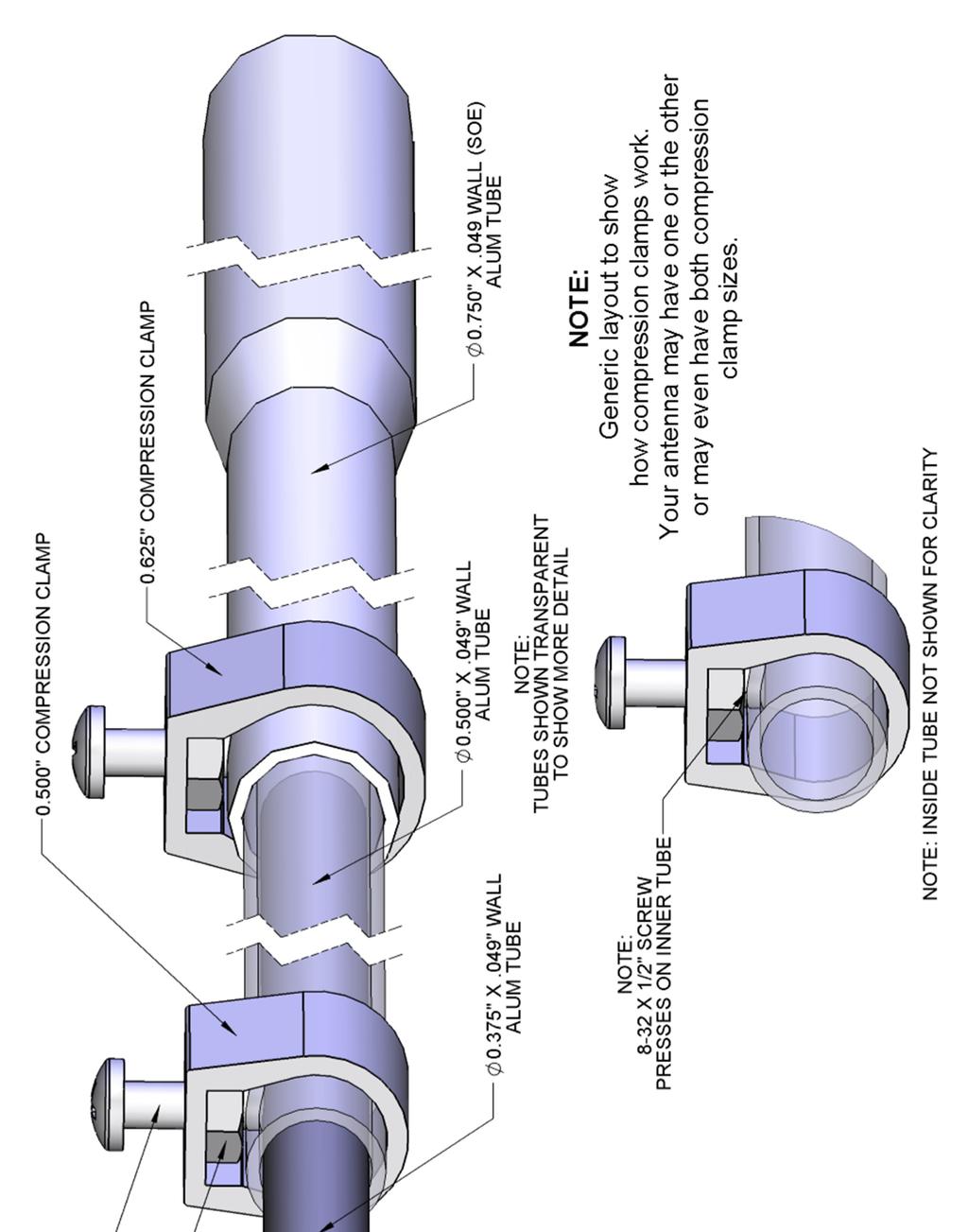

9 GENERIC COMPRESSION CLAMP DETAIL
10 10-30LP8 PARTS & HARDWARE DESCRIPTION... QTY Boom section, 3 x.125 x 180" SWAGED... 1 Boom section, 3 x.125 x 180" STRAIGHT... 1 Sleeve, Director 7/8 x.058 x Sleeve, 1-3/8 x.058 x 24"... 2 Sleeve, 1-1/8 x.058 x Element butt section, 1-1/2 x.058 x 60" SOE,... 2 Element butt section, 1-1/4 x.058 x 60" SOE 1/4" hole... 4 Element section, 1-1/4 x.058 x 60 SOE... 2 Element section, 1.0 x.058 x 60 SOE... 6 Element butt section, 1.0 x.058 x 60" SOE 1/4" hole... 8 Element section, 3/4 x.049 x 60" SOE... 6 Element butt section, 3/4 x.049 x 60" SOE 1/4" hole... 2 Element tip section, 3/4 x.049 x 73.00"... 2 Element tip section, 3/4 x.049 x 62.25"... 2 Element tip section, 3/4 x.049 x 38.50"... 2 Element tip section, 3/4 x.049 x 22.5"... 2 Element tip section, 1/2 x.049 x 67.0"... 2 Element tip section, 1/2 x.049 x 62.50"... 2 Element tip section, 1/2 x.049 x 40.25"... 2 Element tip section, 1/2 x.049 x 24.5"... 2 Rod, phasing, 3/16 x 83.75"... 2 Rod, phasing, 3/16 x "... 2 Rod, phasing, 3/16 x 59.25"... 2 Rod, phasing, 3/16 x 48.5"... 2 Rod, phasing, 3/16 x 41.0"... 2 Rod, phasing, 3/16 x 35.0"... 2 Rod insulator, 1-1/4 x 24" fiberglass... 1 Rod insulator, 1 x 24" fiberglass... 2 Rod insulator, 7/8 x 29.75" fiberglass... 4 Boom to mast plate, 8 x 8 x 1/4" alum Balun, 4:1 ferrite core, 3 KW... 1 IN HARDWARE BOX Clamp plate, 1/2 x 3 x 6",.625 radius, alum... 2 Clamp plate, 1/2 x 3 x 6",.500 radius, alum... 4 Clamp plate, small HF, 1/2 x 2-1/2 x 4" alum Clamp cap, small HF, 3/8 x 1-3/4 x 4" alum Clamp cradle, 1/2 x 1.0 x 4" alum Element clamp block, 3/8 x 1-3/4 x 2-5/8" with 1-1/2" hole... 2 Element clamp block, 3/8 x 1-1/2 x 2-7/16" with 1-1/4" hole... 4 Element clamp block, 3/8 x 1-1/4 x 2-3/16" with 1" hole... 8 Disc insulator, 3/8 x 2" polyethylene, 1-1/4" hole... 2 Disc insulator, 3/8 x 2" polyethylene, 1" hole... 4 Disc insulator, 3/8 x 2" polyethylene, 7/8" hole... 8 Spacer standoff, 3/4 x 3.0" Delrin,... 6 Turnbuckle plate, 2 x 5 x 3/16"... 1 Balun mounting plate, 1 x 1 x Eyebolts, 3/8" x 6"... 2 Turnbuckles, 3/8" hook and eye... 2 Support rope, 5/16 x 30 ft. Dacron,... 1 U-bolt, 3"... 3
11 10-30LP8 PARTS & HARDWARE U-bolt, 2" ST... 1 U-bolt, 2" HD... 4 U-bolt, 2-1/2"... 1 Nylon ties, large 14.5" black Coil, #10 AWG, 16T... 1 Compresion Clamp, 5/ Assembly manual... 1 Zinc Paste ( Penetrox, Noalox or equivalent) container... 1 IN HARDWARE BAG Nut, 3/8-16 stainless Lock washer, 3/8" split ring stainless Nut, 5/6-18, stainless... 4 Lock washer, 5/16" split ring, stainless... 4 Bolt, 1/4-20 x 5 stainless... 2 Bolt, 1/4-20 x 3-1/2" stainless... 6 Bolt, 1/4-20 x 3" stainless... 8 Bolt, 1/4-20 x 2-3/4" stainless Bolt, 1/4-20 x 2-1/2" stainless Bolt, 1/4-20 x 2.0" stainless... 4 Bolt, 1/4-20 x 1-3/4" stainless Bolt, 1/4-20 x 1-1/2" stainless... 8 Screw, 1/4-20 x 1" countersunk, flathead, stainless Nut, 1/4-20 locking, stainless Screw, 8-32 x 2" panhead stainless... 2 Screw, 8-32 x 1-3/4 panhead, stainless... 8 Screw, 8-32 x 1-1/2" panhead, stainless Screw, 8-32 x 1-1/4" panhead, stainless Screw, 8-32 x 1/2" panhead, stainless... 8 Nut, 8-32 locking, stainless Nut, 8-32, stainless... 8 Small phasing line clamp plate, 1/4 x 3/4 x 1-1/4" M 2 ANTENNA SYSTEMS, INC N. SELLAND AVE. FRESNO, CA (559) FAX: sales@m2inc.com

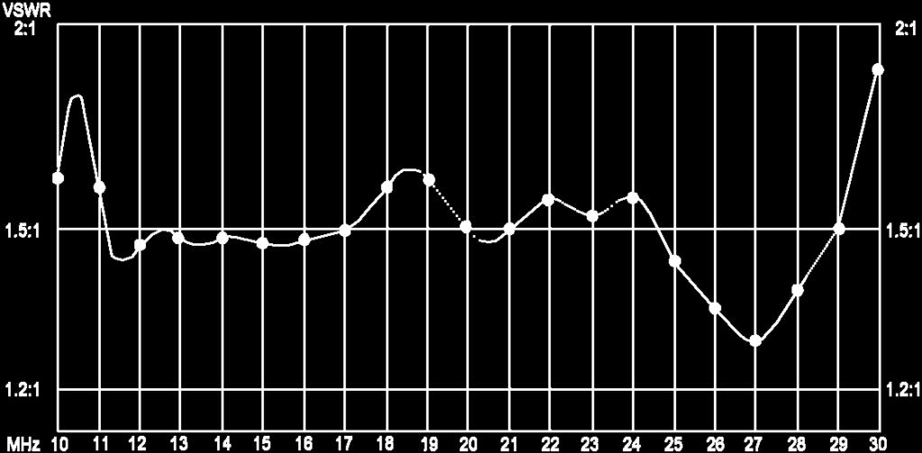
12 10-30LP8 VSWR
M2 Antenna Systems, Inc. Model No: 10-30LP8
 M2 Antenna Systems, Inc. Model No: 10-30LP8 VSWR 2:1 TYPICAL VSWR @ 70 FT. 2:1 1.5:1 1.5:1 1.2:1 1.2:1 10 14 MHz 11 12 13 17 15 16 18 19 20 21 22 23 24 25 26 27 28 29 30 SPECIFICATIONS: Model...10-30LP8
M2 Antenna Systems, Inc. Model No: 10-30LP8-125
 M2 Antenna Systems, Inc. Model No: 10-30LP8-125 VSWR 2:1 TYPICAL VSWR @ 70 FT. 2:1 1.5:1 1.5:1 1.2:1 1.2:1 10 14 MHz 11 12 13 17 15 16 18 19 20 21 22 23 24 25 26 27 28 29 30 SPECIFICATIONS: Model...10-30LP8-125
M2 Antenna Systems, Inc. Model No: 20M6-125
 M2 Antenna Systems, Inc. Model No: 20M6-125 SPECIFICATIONS: Model... 20M6-125 Frequency Range... 14.0 14.350 MHz *Gain, (FS) / Over gnd... 11.19dBi / 16.6dBi @70 Front to back... 25 db Typical Beamwidth...
M2 Antenna Systems, Inc. Model No: 20M5LD
 M2 Antenna Systems, Inc. Model No: 20M5LD SPECIFICATIONS: Model... 20M5LD Frequency Range... 14.0 14.350 MHz *Gain (Full Band)... 10.2 dbi Typical Front to back... 23 db Typical Beamwidth... E=50 / H=66
M2 Antenna Systems, Inc. Model No: 40M3L
 M2 Antenna Systems, Inc. Model No: 40M3L SPECIFICATIONS: Model... 40M3L Frequency Range... 7.0-7.3 MHz X 150 khz Gain... 6.6 dbi Front to back... 23 db Beamwidth... E=62 Feed type... Hair pin match Feed
M2 Antenna Systems, Inc. Model No: 7&10-30LP8
 M2 Antenna Systems, Inc. Model No: 7&10-30LP8 2:1 100KHz BANDWIDTH@ 1.8:1 VSWR 1.5:1 6.9 7.0 7.1 10 FREQUENCY (MHZ) 20 SPECIFICATIONS: Model...7&10-30LP8 Skip log Frequency Range...10-30 MHz Continuous
M2 Antenna Systems, Inc. Model No: 2M4
 M2 Antenna Systems, Inc. Model No: 2M4 SPECIFICATIONS: Model... 2M4 Frequency Range... 144 To 148 MHz *Gain... 9.6 dbi Front to back... 20 db Typical Beamwidth... E=54 H=74 Feed type... T Match Feed Impedance....
M2 Antenna Systems, Inc. Model No: YAGI ANTENNA
 M Antenna Systems, Inc. Model No: 4.5-7 YAGI ANTENNA SPECIFICATIONS: Model... 4.5-7 Frequency Range... 4.0 To 4.5 MHz *Gain... 0 To 7 dbi Front to back... 0 db over the rear 80 Beamwidth... E=44 H=50 typical
M2 Antenna Systems, Inc. Model No: KT31WARC
 M2 Antenna Systems, Inc. Model No: KT31WARC SPECIFICATIONS: Model... KT31WARC Frequency Range... 10.1-10.15 MHz **Selectable Frequency Range... 14.0-14.35 MHz **Selectable... (175 KHz / 2:1 VSWR Nominal)
M2 Antenna Systems, Inc. Model No: 2M7
 M2 Antenna Systems, Inc. Model No: 2M7 SPECIFICATIONS: Model... 2M7 Frequency Range... 144 To 148 MHz *Gain... 12.3 dbi Front to back... 20 db Typical Beamwidth... E=43 H=50 Feed type... T Match Feed Impedance....
M2 Antenna Systems, Inc. Model No: 2M5WL
 M2 Antenna Systems, Inc. Model No: 2M5WL SPECIFICATIONS: Model... 2M5WL Frequency Range... 144 To 148 MHz *Gain... 16.84 dbi Front to back... 22 db Typical Beamwidth... E=26 H=29 Feed type... T Match Feed
M2 Antenna Systems, Inc. Model No: 40M2L
 M2 Antenna Systems, Inc. Model No: 40M2L SPECIFICATIONS: Model...40M2L Frequency Range...6.9-10 MHz X 150 khz Gain...5.5 dbi Front to back...13 15 db Beamwidth...E=74 Feed type...hair pin match Feed Impedance....50
M2 Antenna Systems, Inc. Model No: 2MCP22
 M2 Antenna Systems, Inc. Model No: 2MCP22 SPECIFICATIONS: Model... 2MCP22 Frequency Range... 144 To 148 MHz *Gain... 14.39 dbic Front to back... 25 db Typical Elipticity... >3db Beamwidth... 38 Feed type...
M2 Antenna Systems, Inc. Model No: 436CP30
 M2 Antenna Systems, Inc. Model No: 436CP30 SPECIFICATIONS: Model... 436CP30 Frequency Range... 432 To 440 MHz *Gain... 15.50 dbic Front to back... 18 db Typical Elipticity... 1.5 db Typical Beamwidth...
M2 Antenna Systems, Inc. Model No: 456CP34
 M2 Antenna Systems, Inc. Model No: 456CP34 SPECIFICATIONS: Model... 456CP34 Frequency Range... 435 To 470 mhz *Gain... 16.0 dbi Front to back... 23 db Typical Beamwidth... 30 Circular Feed type... T Match
M2 Antenna Systems, Inc. Model No: 450CP26
 M2 Antenna Systems, Inc. Model No: 450CP26 SPECIFICATIONS: Model... 450CP26 Frequency Range... 445 To 455 mhz *Gain... 16.5 dbi Front to back... 21 db Typical Beamwidth... 30 Circular Feed type... T Match
M2 Antenna Systems, Inc. Model No: 450CP34
 M2 Antenna Systems, Inc. Model No: 450CP34 SPECIFICATIONS: Model... 450CP34 Frequency Range... 435 To 455 mhz *Gain... 16.0 dbi Front to back... 22 db Typical Beamwidth... 28 Circular Feed type... T Match
M2 Antenna Systems, Inc. Model No: 6M8GJ
 M2 Antenna Systems, Inc. Model No: 6M8GJ SPECIFICATIONS: Model... 6M8GJ Frequency Range... 50.0 To 50.4 mhz *Gain, (FS) / Over gnd... 14.2 dbi / 19 dbi @ 20 Front to back... 20 db Typical Beamwidth...
M2 Antenna Systems, Inc. Model No: 435XP50
 M2 Antenna Systems, Inc. Model No: 435XP50 SPECIFICATIONS: Model... 435XP50 Frequency Range... 430 To 436 MHz *Gain... 19.2 dbi Front to back... 22 db Typical Cross pol. isolation... >20 db Typical Beamwidth...
THIS SHOULD TWEAK YOUR IMAGINATION
 10-27-05 THIS SHOULD TWEAK YOUR IMAGINATION SPECIFICATIONS FOR SINGLE ANTENNA MODEL NUMBER... 432EME-12 FREQUENCY... 430-436 MHz GAIN... 14.4 dbd FRONT TO BACK... 23 db VSWR... 1.2:1 TYPICAL BEAMWIDTH...
M2 Antenna Systems, Inc. Model No: KT34XA TO KT36XA UPGRADE KIT
 M2 Antenna Systems, Inc. Model No: KT34XA TO KT36XA UPGRADE KIT SPECIFICATIONS: SPECIFICATIONS for the KT34-6XA MODEL NUMBER...KT36XA FREQ. RANGE...14.0-14.35 MHz 21.0-21.45 MHz 28.0-29.0 MHz GAIN (Free
M2 Antenna Systems, Inc. Model No: HFTB6MXP20-2X2
 M2 Antenna Systems, Inc. Model No: HFTB6MXP20-2X2 FRONT OF SYSTEM REAR OF SYSTEM SPECIFICATIONS: Model... HFTB6MXP20-2X2 Band... 6M Antenna... 6MXP20 T-Brace... Y Cross Boom Dia... 4.5 Wind Load w/o Ant.....
M2 Antenna Systems, Inc. Model No:
 M2 Antenna Systems, Inc. Model No: 400-600-10 SPECIFICATIONS: Model... 400-600-10 Frequency Range... 390 To 650 MHz *Gain... 12 To 13 dbic Front to back... 20 db Nominal Beamwidth... 46 Nominal Feed Impedance....
M2 Antenna Systems, Inc. Model No: HFTB2MXP X2-1K
 M2 Antenna Systems, Inc. Model No: HFTB2MXP28-32-2X2-1K FRONT OF SYSTEM REAR OF SYSTEM SPECIFICATIONS: Model... HFTB2MXP28-32-2X2-1K Band... 2M Antenna... 2MXP28-32 T-Brace... Y Cross Boom Dia... 3.0 Wind
M2 Antenna Systems, Inc. Model No: FGHFTB2MXP202X2
 M2 Antenna Systems, Inc. Model No: FGHFTB2MXP202X2 FRONT OF SYSTEM REAR OF SYSTEM SPECIFICATIONS: Model... HFTB2MXP20-2X2 Band... 2M Antenna... 2MXP20 T-Brace... Y Cross Boom Dia... 3.0 Wind Load w/o Ant.....
M2 Antenna Systems, Inc. Model No: HFTB2MXP X2-3K
 M2 Antenna Systems, Inc. Model No: HFTB2MXP28-32-2X2-3K FRONT OF SYSTEM REAR OF SYSTEM SPECIFICATIONS: Model... HFTB2MXP28-32-2X2-3K Band... 2M Antenna... 2MXP28-32 T-Brace... Y Cross Boom Dia... 3.0 Wind
M2 Antenna Systems, Inc. Model No: 2M HO LOOP
 M2 Antenna Systems, Inc. Model No: 2M HO LOOP SPECIFICATIONS: Model... 2M HO LOOP Frequency Range... 144 To 144.5 MHz Gain, Typical @ 10 ft.... 4 dbd @ 10 deg. Gain, 2 STK @ 82 & 132... 8 dbd @ 9 deg.
Directive Systems & Engineering 2702 Rodgers Terrace Haymarket, VA
 Directive Systems & Engineering 2702 Rodgers Terrace Haymarket, VA 20169 1628 www.directivesystems.com 703 754 3876 K1JX DESIGNED 6 ELEMENT 50 MHZ YAGI, DSEJX6 50 INTRODUCTION The Directive Systems DSEJX6-50
Assembly Instructions: Bencher Skylark
 Assembly Instructions: Bencher Skylark Tools Required: Pop Rivet Tool Tape Measure Hex Wrenches Screwdriver Several Disposable Rags Two Saw Horses Several boxes or bowls to hold fasteners and small parts
K1FO 12 ELEMENT 144/147 MHz YAGI
 K1FO 12 ELEMENT 144/147 MHz YAGI WARNING: INSTALLATION OF THIS PRODUCT NEAR POWER LINES IS DANGEROUS. FOR YOUR SAFETY FOLLOW THE INSTALLATION DIRECTIONS. Ariane Arrays, Inc. Copyright 2006 201 Hopedale
MI: (Secure this number someplace, for possible future need) SPECIFICATIONS:
 SPECIFICATIONS:") 6C ASSEMBLY INSTRUCTIONS ANTENNA MODEL T6 MI: 030927 (Secure this number someplace, for possible future need) SPECIFICATIONS: FORWARD GAIN 5.1 dbd F:B RATIO 15-25 db (Rises with frequency) FREQUENCY COVERAGE
6C ASSEMBLY INSTRUCTIONS ANTENNA MODEL T6 MI: 030927 (Secure this number someplace, for possible future need) SPECIFICATIONS: FORWARD GAIN 5.1 dbd F:B RATIO 15-25 db (Rises with frequency) FREQUENCY COVERAGE
Model VB-23FM 2-Meter 3-Element Beam
 308 Industrial Park Road Starkville, MS 39759 USA Ph: (662) 323-9538 FAX: (662) Model VB-23FM 2-Meter 3-Element Beam [ INSTRUCTION MANUAL Figure 1 Overall View and Boom Detail GENERAL DESCRIPTION This
INSTRUCTION MANUAL. Specifications Mechanical. 1 5/8 to 2 1/16 O.D. (41mm to 52mm)
") 308 Industrial Park Road Starkville, MS 39759 USA Ph: (662) 323-9538 FAX: (662) 323- General Description Model VB-25FM 2-Meter 5 Elements Beam INSTRUCTION MANUAL This antenna is a 5-element, 2-meter beam
308 Industrial Park Road Starkville, MS 39759 USA Ph: (662) 323-9538 FAX: (662) 323- General Description Model VB-25FM 2-Meter 5 Elements Beam INSTRUCTION MANUAL This antenna is a 5-element, 2-meter beam
TZ-RD-1740 Rotary Dipole Instruction Manual
 TZ-RD-1740 17/40m Rotary Dipole Instruction Manual The TZ-RD-1740 is a loaded dipole antenna for the 40m band and a full size rotary dipole for the 17m band. The antenna uses an aluminium radiating section
JK M Hi-Q Coil Loaded Rotatable Dipole Version
 JK-401 40M Hi-Q Coil Loaded Rotatable Dipole 2018 Version 72 Grays Bridge Road, Unit D, Brookfield, CT 06804 845.228.8700 (TEL) 845.279.5526 (FAX) info@jkantennas.com LAST UPDATED: 02-01-2018 JK Antennas
INSTRUCTION MANUAL. Specifications Electrical. Front-To-Back Ratio VSWR at Resonance Less than 1.5:1 Nominal Impedance. Mechanical
 300 Industrial Park Road, Starkville, MS 39759 Ph: (662) 323-8538 FAX: (662) 323-6551 TH-3JRS Tri-band HF 3 Elements Beam Covers 10, 15 and 20 Meters INSTRUCTION MANUAL WARNING Installation of this product
Directive Systems & Engineering 2702 Rodgers Terrace Haymarket, VA
 Directive Systems & Engineering 2702 Rodgers Terrace Haymarket, VA 20169-1628 www.directivesystems.com 703-754-3876 25 Element 7.4 wl. K1FO Designed Yagi, Model DSEFO432-25 ELECTRICAL SPECIFICATIONS Frequency
Kwik-Lock. Installation Instructions. Attention Dealers: Please give this owners manual to the customer when the product is delivered.
 Serving the Truck & Trailer Industry Since 1944 Installation Instructions Attention Dealers: Please give this owners manual to the customer when the product is delivered. Call 800-535-9545 www.aeroindustries.com
INSTRUCTION MANUAL ORDER NO. V3R MODEL V3R. Collinear Gain Vertical for MHz
 ORDER NO. V3R MODEL V3R Collinear Gain Vertical for 216-225 MHz INSTRUCTION MANUAL General Description The new Hy-Gain V3R VHF antenna is a collinear 5/8-wave omnidirectional vertical antenna for the 216-225
MODEL DB-1015A 10- and 15-Meter Duo-Band Antenna Order No. 330
 MODEL DB-1015A 10- and 15-Meter Duo-Band Antenna Order No. 330 HY-GAIN ELECTRONICS CORPORATION 8601 Northeast Highway 6 Lincoln, Nebraska 68505 Telephone 464-9151 Area Code 402 TABLE OF CONTENTS page SECTION
JK-65 Five Element 6M Yagi
 JK-65 Five Element 6M Yagi PO Box 266, Croton Falls, NY 10519-0266 845.228.8700 (TEL) 845.279.5526 (FAX) info@jkantennas.com Page 1 of 8 JK Antennas Limited Warranty and Liability JK Antennas ( Manufacturer
Model BiConiLog Antenna. User Manual
 Model 3149 BiConiLog Antenna User Manual ETS-Lindgren Inc. reserves the right to make changes to any products herein to improve functioning or design. Although the information in this document has been
INSTRUCTION MANUAL V-42R. Dual Band Collinear Gain Vertical for MHz and GENERAL DESCRIPTION
 308 Industrial Park Road, Starkville, MS 39759 USA Ph: (662) 323-9538 FAX: (662) 323-6551 V-42R Dual Band Collinear Gain Vertical for 144-148 MHz and 436-450 INSTRUCTION MANUAL GENERAL DESCRIPTION The
HFp. User s Guide. Vertical. entenna. 7 MHz 30 MHz Amateur Radio Antenna Plus 6-Meters
 User s Guide HFp Vertical 7 MHz 30 MHz Amateur Radio Antenna Plus 6-Meters The Ventenna Co. LLC P.O. Box 2998, Citrus Heights, CA, 956 www.ventenna.com entenna Table of Contents The HFp Antenna -------------------------------------------------------------------
INSTRUCTION MANUAL. Model 18AVQII Five Band Vertical Antenna 10, 15, 20, 40, 80 Meter. General Description. Theory of Operation
 Model 18AVQII Five Band Vertical Antenna 10, 15, 20, 40, 80 Meter 308 Industrial Park Road Starkville, MS 39759 (662) 323-9538 Fax: (662) 323-5803 INSTRUCTION MANUAL General Description The Hy-Gain 18AVQII
Standard Pole Mount Parabolic Antenna Mounting Instructions 3 ft. (90cm) & 4 ft. (120cm)
 & 4 ft. (120cm)") 495 R Billerica Ave. N. Billerica, MA 01862 USA Tel: (978) 459-8800 Fax: (978) 459-3310 / 8814 www.radiowavesinc.com email: sales@radiowavesinc.com Standard Pole Mount Parabolic Antenna Mounting Instructions
495 R Billerica Ave. N. Billerica, MA 01862 USA Tel: (978) 459-8800 Fax: (978) 459-3310 / 8814 www.radiowavesinc.com email: sales@radiowavesinc.com Standard Pole Mount Parabolic Antenna Mounting Instructions
REP Design LLC. 193 Winding Ridge Rd, Southington, CT INSTALLATION INSTRUCTIONS:
 REP Design LLC 193 Winding Ridge Rd, Southington, CT 06489 1-860.426.1894 n7emw@cox.net www.repdesign.us INSTALLATION INSTRUCTIONS: SHD-SO239 Super Heavy Duty SO-239Antenna Mounting System Thank you for
Spiderbeam Balun Construction Guide
 BALUN CONSTRUCTION GUIDE Ver. 1.0 1 The components of the Balun Kit are in a plastic bag. Most of the components are inside the plastic case of the balun. The aluminum U-profile and the RG-142 Teflon Coax
INSTRUCTION MANUAL for MODEL TH6-DX "THUNDERBIRD" (389)
") INSTRUCTION MANUAL for MODEL TH6-DX "THUNDERBIRD" (389) HY-GAIN ELECTRONICS CORPORATION, N. E. Hwy #6 at Stevens Creek, Lincoln, Nebraska 65801 Telephone 434-6331 INTRODUCTION Ely-Gain's new Model TH6-DX
INSTRUCTION MANUAL for MODEL TH6-DX "THUNDERBIRD" (389) HY-GAIN ELECTRONICS CORPORATION, N. E. Hwy #6 at Stevens Creek, Lincoln, Nebraska 65801 Telephone 434-6331 INTRODUCTION Ely-Gain's new Model TH6-DX
LJ element beam for 10 or 12 meters INSTRUCTION MANUAL. CAUTION: Read All Instructions Before Operating Equipment
 LJ-113 3 element beam for 10 or 1 meters INSTRUCTION MANUAL CAUTION: Read All Instructions Before Operating Equipment 308 Industrial Park Road Starkville, MS 39759 USA Tel: 66-33-9538 Fax: 66-33-6551 VERSION
INSTRUCTION MANUAL. Model VB-215DX MECHANICAL DESIGN GENERAL DESCRIPTION ELECTRICAL DESIGN. 2 Meter 15 Element Yagi for SSB/CW
 Model VB-215DX 2 Meter 15 Element Yagi for SSB/CW INSTRUCTION MANUAL GENERAL DESCRIPTION The Hy-Gain Model 215DX is a high performance yagi antenna for SSB/CW DXing in the Amateur 2 meter band. It features
Classic Roll Tarp. Installation Instructions. Attention Dealers: Please give this owners manual to the customer when the product is delivered.
 Serving the Truck & Trailer Industry Since 1944 Classic Roll Tarp Attention Dealers: Please give this owners manual to the customer when the product is delivered. Call 800-535-9545 www.aeroindustries.com
southpaw enterprises, inc.
 southpaw enterprises, inc. Instruction Sheet C-STAND 7100 Store these instructions in a safe place or with the enclosed maintenance checklist Take time to familiarize yourself with the use and maintenance
Installation and Assembly - Universal Articulating Swivel Double-Arm for 42" - 60" Plasma Screens
 Installation and Assembly - Universal Articulating Swivel Double-Arm for 42" - 60" Plasma Screens Models: PLAV 70-UNL, PLAV 70-UNL-S PLAV 70-UNLP, PLAV 70-UNLP-S R This product is UL Listed. It must be
Classic Roll Tarp. Installation Instructions. Attention Dealers: Please give this owners manual to the customer when the product is delivered.
 Serving the Truck & Trailer Industry Since 1944 Classic Roll Tarp Attention Dealers: Please give this owners manual to the customer when the product is delivered. Call 800-535-9545 www.aeroindustries.com
DB Duo-Monoband Beam 7 - Element, 12 and 17 Meter INSTRUCTION MANUAL. General Description
 308 Industrial Park Road Starkville, MS 39759 USA Ph: (662) 323-9538 FAX: (662) 323-6551 DB- 1217 Duo-Monoband Beam 7 - Element, 12 and 17 Meter INSTRUCTION MANUAL General Description The Hy-Gain DB-1217
installation guide 1 GUIDE#: pwb-assault-001
 assault WAKEBOARD tower installation guide INSTALLATION SUPPORT 1 important information This Aerial wakeboard tower fits motor boats with 76-108 inch wide beam widths. This measurement is taken from the
installation guide 1 GUIDE#: pwb-assault-004
 assault WAKEBOARD tower installation guide INSTALLATION SUPPORT 1 important information This Aerial wakeboard tower fits motor boats with 76-108 inch wide beam widths. This measurement is taken from the
TELEX, liutiiilio"i TELEX COMMUNICATIONS, INC ALDRICH AVE. SO. MINNEAPOLIS. MN USA
 TELEX, liutiiilio"i TELEX COMMUNICATIONS, INC. 9600 ALDRICH AVE. SO. MINNEAPOLIS. MN 55420 USA INSTRUCTION MANUAL ORDER NO. 410 General This antenna is a five-element, Citizens Band beam with a forward
Assembly Instructions for the 10N6RDB Antenna
 Assembly Instructions for the 10N6RDB Antenna The 10N6RDB antenna comes from the factory almost completely assembled. All you have to do is install the 1/2 inch Aluminum tubing at both ends of the 10 Meter
MFJ-2982 Feather-Lite 80-6 Meter Vertical Antenna
 MFJ-2982 Feather-Lite 80-6 Meter Vertical Introduction: The MFJ-2982 is a lightweight 31-foot fiberglass antenna designed to mount on any convenient post, mast, or a suitable wide-stance tripod such as
JK-404 GRANDE Four Element Full Size 40M Yagi
 JK-404 GRANDE Four Element Full Size 40M Yagi PO Box 266, Croton Falls, NY 10519-0266 845.228.8700 (TEL) 845.279.5526 (FAX) info@jkantennas.com JK Antennas Limited Warranty and Liability JK Antennas (
HOUSE PARTS PACKED IN HOUSE BOX PARTS IN PLASTIC BAG (HARDWARE) PARTS IN SMALL PLASTIC BAG (FLOOR CLIPS) PARTS PACKED IN BUNDLE
 PARTS IN SMALL PLASTIC BAG (FLOOR CLIPS) PARTS PACKED IN BUNDLE") Check parts against this list before starting assembly. Refer to illustrations on pages 6 and 7 to view house parts. If any shortages are found, refer to Packing Slip for claim instructions. Item 3 5 6
Check parts against this list before starting assembly. Refer to illustrations on pages 6 and 7 to view house parts. If any shortages are found, refer to Packing Slip for claim instructions. Item 3 5 6
Cushcraft. Amateur Radio Antennas DB-46M8EL. Dual band 6 and 4 Meter, 8 Element Beam Antenna INSTRUCTION MANUAL
 Cushcraft Amateur Radio Antennas DB-46M8EL Dual band 6 and 4 Meter, 8 Element Beam Antenna INSTRUCTION MANUAL CAUTION: Read All Instructions Before Operating Equipment VERSION 1B Cushcraft Amateur Radio
MOUNTING INSTRUCTIONS
 Standard Mounting Bracket Tilting Bracket* Mounting example Right side for upper tilt from 0 to 20 20 Spare parts: p/n SA197 Materials: extruded aluminum Hardware: stainless & zinc plated steel Dimensions
PowerLock. Installation Instructions. Attention Dealers: Please give this owners manual to the customer when the product is delivered.
 Serving the Truck & Trailer Industry Since 1944 FOR Attention Dealers: Please give this owners manual to the customer when the product is delivered. Call 800-535-9545 www.aeroindustries.com Indianapolis,
OXYGEN INSTALLATION. Revision date
 12345 1 Hardware List 12345 Flat head wood screw #9 x 7/8 long with #2 Phillips drive, silver Used to attach surfaces and end panels Hex set screw ½-13 x 2 long with 1/4 hex drive, black Used on Legs Hex
HFp. User s Guide. Vertical. entenna. 7 MHz 54 MHz Amateur Radio Antenna. The Ventenna Co. LLC P.O. Box 227 Huston, ID
 User s Guide HFp Vertical 7 MHz 54 MHz Amateur Radio Antenna The Ventenna Co. LLC P.O. Box 227 Huston, ID 83630 www.ventenna.com entenna Table of Contents The HFp Antenna -------------------------------------------------------------------
MTS-SP100. RENOGY Pole Mount System E Philadelphia St, Ontario, CA Version: 1.2
 MTS-SP100 RENOGY Pole Mount System 2775 E Philadelphia St, Ontario, CA 91761 1-800-330-8678 1 Version: 1.2 Important Safety Instructions Please save these instructions. This manual contains important safety,
ASSEMBLING MANUAL LS 86. HF Log Periodic Antenna MHz
 ASSEMBLING MANUAL LS 86 HF Log Periodic Antenna 14 30 MHz ACOM LS86 HF Log-periodic Antenna ASSEMBLING MANUAL 1. GENERAL INFORMATION ACOM manufactures a range of antennas designed and produced to give
TENNADYNE. Aluminum with a PhD. Tennadyne ASSEMBLY INSTRUCTIONS MODEL: T Log Periodic Antennas SPECIFICATIONS:
 TENNADYNE Aluminum with a PhD ASSEMBLY INSTRUCTIONS MODEL: T10-100224 SPECIFICATIONS: FREQUENCY COVERAGE 13-33 MHz FORWARD GAIN 6.1 dbd ½ POWER BEAMWIDTH 52 DEGREES F:B RATIO To 25 Db (Rises with frequency)
MantelMount. TM1A Installation Instructions IMPORTANT SAFETY INSTRUCTIONS - SAVE THESE INSTRUCTIONS
 MantelMount TMA Installation Instructions IMPORTANT SAFETY INSTRUCTIONS - SAVE THESE INSTRUCTIONS TM Thank you for choosing the MantelMount television wall mount. Please read this entire manual before
MFJ-1835K34 40,30 METER ADD ON KIT FOR THE MFJ-1835 COBWEB ANTENNA INSTRUCTION MANUAL. CAUTION: Read All Instructions Before Operating Equipment
 MFJ-1835K34 40,30 METER ADD ON KIT FOR THE MFJ-1835 COBWEB ANTENNA INSTRUCTION MANUAL CAUTION: Read All Instructions Before Operating Equipment 300 Industrial Park Road Starkville, MS 39759 USA Tel: 662-323-5869
The W3FF Portable Dipole
 The W3FF Portable Dipole This is the antenna I designed for my 'walking portable' station. It is a dipole constructed out of the plastic plumbing pipe CPVC. There are telescoping whips at the ends of each
Installation and Assembly - Universal Articulating Swivel Double-Arm for 42" - 60" Plasma Screens
 Installation and Assembly - Universal Articulating Swivel Double-Arm for 42" - 60" Plasma Screens Models: PLAV 70-UNL, PLAV 70-UNL-S PLAV 70-UNLP, PLAV 70-UNLP-S R This product is UL Listed. It must be
INSTRUCTION MANUAL VB-66DX. 6-Meter 6-Element Beam. Preparation For Assembly. General Description
 VB-66DX 308 Industrial Park Road Starkville, MS 39759 USA Ph: (662) 323-9538 FAX: (662) 323-6551 6-Meter 6-Element Beam INSTRUCTION MANUAL General Description The Hy-Gain Model 66DX is a full sized 6-
BEAST THE. Tube and Pipe Notcher Operating Instructions. Notches In Bends Straight Notches. Angled Notches. Offset Notches
 Copyright (c) 2007 J D SQUARED INC. www.jd2.com THE BEAST Tube and Pipe Notcher Operating Instructions Notches In Bends Straight Notches Angled Notches PATENT PENDING Offset Notches Assembly After unpacking
Slide the stock rubber tank mount caps onto the ends of the CS-1 tank mount:
 RYCA CS-1 BODY PARTS INSTALLATION GUIDE [The CS-1 installation guides should be used as supplements to the videos found on our Youtube Channel. There is no strict order to the build process, but it is
 www.wildmanconstruction.com Changing your toilet is an easy project that should take half a day or less. The most common toilet has a separate tank that mounts on top of the bowl. These instructions apply
CP6 6 Band Trap Vertical 80-6m
 CP6 6 Band Trap Vertical 80-6m Instruction Sheet The CP6 is a multi-band trap-vertical antenna for HF bands, covering the 80*, 40, 20, 15, 10m & 6m amateur bands. Made from heavy duty aluminum, the CP6
MFJ-1762 Instruction Manual
 MFJ-1762 Instruction Manual INTRODUCTION Thank you for purchasing the MFJ-1762 three-element six-meter Yagi. The MFJ-1762 is a light-weight directional antenna especially designed for installation with
PAC-12 Kit Contents. Tools Needed Soldering iron Phillips screwdriver Wire stripper Wrenches, 7/16 and 1/2 Terminal crimp tool Pliers Solder
 PAC-2 Kit Contents Part Quantity Screws: 8/32 x 3/8 Screws: 8-32 x 5/6 Screw: 8-32 x /4 #8 internal tooth washers #8 solder lug ring terminals Bolt: Aluminum, /4-20 x.5 /4 internal tooth washer Nut: Aluminum
Pacific Antenna 20 and 40M Lightweight Dipole Kit
 Pacific Antenna 20 and 40M Lightweight Dipole Kit Diagram showing configuration and approximate lengths 8 3 16 9 16 9 8 3 Description The Pacific Antenna lightweight dual band, trap dipole kit provides
GlideRite Retractable Cover System For Hot Spot Spas (SE & SLX only)
") List of Contents Quantity Description 12 #10 x 1 ½ Flat Head Phillips Screw (see pg. 2) 2 #10 x ½ Pan Head Phillips Screw (see pg. 2) 8 ¼ x 2 ½ Lag Bolt (see pg. 2) 7 ¼ 20 x 5 / 8 Hex Head Bolt (see pg.
List of Contents Quantity Description 12 #10 x 1 ½ Flat Head Phillips Screw (see pg. 2) 2 #10 x ½ Pan Head Phillips Screw (see pg. 2) 8 ¼ x 2 ½ Lag Bolt (see pg. 2) 7 ¼ 20 x 5 / 8 Hex Head Bolt (see pg.
TELEX COMMUNICATIONS, INC ALDRICH LIVE SO. MINNEAPOLIS. MN U S A. /~g-~~~~r iu IORDER NO. 337s
 IkEfEX N TELEX COMMUNICATIONS, INC. 300 ALDRICH LIVE SO. MINNEAPOLIS. MN 55420 U S A /~g-~~~~r iu IORDER NO. 337s MAN A I MODEL V4S Collinear Gain Vertical for 420450 MHz PN801910 General Description The
Hardware and Components:
 Hardware and Components: (A) 4X 5/16 x 1 Carriage Bolt (B) 2X 5/16 x 2-1/4 Carriage Bolt (C) 2X 5/16 x 3-1/4 Hex Bolt (D) 2X 5/16 x 3/4 Hex Bolt (E) 2X 5/16 x 1-1/4 Hex Bolt (F) 5/16 x 2-1/4 Hex Bolt (G)
Installation Manual ZGuard Mounting Options
 Installation Manual ZGuard Mounting Options Above-Counter Heavy-Duty Flange (EZ-Span) (Entire EZ-Span unit not shown) Lift EZ-Span unit up until bottom of 1.5" diameter post clears internal heavy duty
Installation Instructions
 For Medium (15-18.5K) + Heavy duty (22-28.5K) Air Conditioner READ BEFORE INSTALLING UNIT To avoid risk of personal injury, property damage, or product damage due to the weight of this device and sharp
Hatchback Wing Riser Kit
 Hatchback Wing Riser Kit 2015-06-11 Thank you for purchasing this PERRIN product for your car! Installation of this product should only be performed by persons experienced with installation of aftermarket
400A 40113V, 401A 40120V, & 401AL 40120VL ALUMINUM VERTICAL 4000 LB LIFT INCLUDES SCREW LEG ASSEMBLY INSTRUCTIONS
 12/11/07 PAGE 1 OF 12 400A 40113V, 401A 40120V, & 401AL 40120VL ALUMINUM VERTICAL 4000 LB LIFT INCLUDES SCREW LEG ASSEMBLY INSTRUCTIONS Thank you for purchasing our product! *Please read these instructions
User Instructions Multiline Otter Scoreboard Caddy Assembly
 List of parts: User Instructions Multiline Otter Scoreboard Caddy Assembly Single Caddy Double Caddy 1 1 Base assembly with attached wheels 2 4 1 1 2 4 4 8 10 20 12 Uprights (60 or 74 aluminum extrusion)
INSTRUCTION BOOKLET #34. For Wallbed models: KING SIZE SIERRA WITH STORAGE HEADBOARD
 For Wallbed models: KING SIZE SIERRA WITH STORAGE HEADBOARD INSTRUCTION BOOKLET #34 WARNING! ALL MURPHY/WALLBED SYSTEMS CONTAIN STORED ENERGY. FAILURE TO USE AND FOLLOW THESE INSTRUCTIONS DURING THE INSTALLATION
TM12 ASSEMBLY INSTRUCTIONS
 TM12 ASSEMBLY INSTRUCTIONS Congratulations on purchasing the finest purple martin house available. Nature House Brand houses are the proven leader in aluminum martin housing for over half a century. After
Parts list continues on Page 2 HOUSE PARTS PACKED IN HOUSE BOX PARTS IN SMALL PLASTIC BAG (HARDWARE) POST PARTS PACKED IN THIS BOX (LARGE PLASTIC BAG)
 POST PARTS PACKED IN THIS BOX (LARGE PLASTIC BAG)") Form 05-07 Instructions and Parts List MSS- Martin Safety System NOTES: () A complete system is packed in two boxes post box and house box. House box contains hardware for both post and house assembly.
Form 05-07 Instructions and Parts List MSS- Martin Safety System NOTES: () A complete system is packed in two boxes post box and house box. House box contains hardware for both post and house assembly.
Cisco Aironet 13.5-dBi Yagi Mast Mount Antenna (AIR-ANT1949)
") Cisco Aironet 13.5-dBi Yagi Mast Mount Antenna (AIR-ANT1949) Overview This document describes the 13.5-dBi Yagi mast mount antenna and provides instructions for mounting it. The antenna operates in the
Cisco Aironet 13.5-dBi Yagi Mast Mount Antenna (AIR-ANT1949) Overview This document describes the 13.5-dBi Yagi mast mount antenna and provides instructions for mounting it. The antenna operates in the
GlideRite Retractable Cover System For HotSpring & Tiger River Spas (except Classic & pre-2000 Landmark Spas)
") List of Contents Quantity Description 12 #10 x 1 ½ Flat Head Phillips Screw (see pg. 2) 2 #10 x ½ Pan Head Phillips Screw (see pg. 2) 8 ¼ x 2 ½ Lag Bolt (see pg. 2) 7 ¼ 20 x 5 / 8 Hex Head Bolt (see pg.
List of Contents Quantity Description 12 #10 x 1 ½ Flat Head Phillips Screw (see pg. 2) 2 #10 x ½ Pan Head Phillips Screw (see pg. 2) 8 ¼ x 2 ½ Lag Bolt (see pg. 2) 7 ¼ 20 x 5 / 8 Hex Head Bolt (see pg.
/ Rudder Installation Guide
 / Rudder Installation Guide Parts List Part # Part Description Qty Part # Part Description Qty 1030 Plastic Bead 1 1195 Rope; 1/8" Black Nylon 1 @ 9 1044 1/4-20 x 5/8" Pan Head Bolt 2 1353 Sliding Track
No. 412, 414, 416 Operations Manual
 No. 412, 414, 416 Operations Manual CARE: Occasional oiling of moving parts with machine oil will ease operation and extend the life of the brake. Occasionally check and tighten the lower beam bracket
ALWAYS ATTACH THE SAFETY ROPE TO A STABLE SUPPORT BEFORE ATTEMPTING TO ATTACH THE UNIVERSAL MOUNT TO A WINDOW FRAME OR RAIL.
 MFJ-1622 Introduction The MFJ-1622 Antenna was designed to provide portable or permanent HF communications on 40 through 10 meters and VHF on 6 and 2 meters. The universal mount design allows the user
JK BigTri. 3-Band Yagi (20M/15M/10M) 36Ft Boom
 36Ft Boom") JK BigTri 3-Band Yagi (20M/15M/10M) 36Ft Boom 72 Grays Bridge Road, Unit D, Brookfield, CT 06804 845.228.8700 (TEL) 845.279.5526 (FAX) info@jkantennas.com UPDATED : FEB 2017 JK Antennas Limited Warranty
JK BigTri 3-Band Yagi (20M/15M/10M) 36Ft Boom 72 Grays Bridge Road, Unit D, Brookfield, CT 06804 845.228.8700 (TEL) 845.279.5526 (FAX) info@jkantennas.com UPDATED : FEB 2017 JK Antennas Limited Warranty