M2 Antenna Systems, Inc. Model No: 40M3L
|
|
|
- Darcy Sutton
- 5 years ago
- Views:
Transcription


.")
1 M2 Antenna Systems, Inc. Model No: 40M3L SPECIFICATIONS: Model... 40M3L Frequency Range MHz X 150 khz Gain dbi Front to back db Beamwidth... E=62 Feed type... Hair pin match Feed Impedance Ohms Unbalanced Maximum VSWR :1 typ. 2:1 max Input Connector... SO-239, Other avl. Power Handling... 3 kw, Higher avl. Boom Length / Dia / 3.0 x.125 Wall Element Length / Dia Ft Turning Radius: Ft Stacking Distance... Call Mast Size... 2 to 3 Nom. Wind area / Survival Sq. Ft. / 100 MPH Weight / Ship Wt Lbs. / 125 Lbs. *Subtract 2.14 from dbi for dbd FEATURES: The 40M3L is a linear loaded 40 meter Yagi designed with 20 years of experience and listening to customer s needs. The result is a powerful package of clean mechanical design, quality materials, and outstanding performance that will deliver years of enjoyment on the 40 meter band. Mechanically the elements are mounted between 1/2 thick, machined aluminum clamp plates! The Driven element is split and insulated with a 1-1/4 inch solid fiberglass rod and fed with a weather sealed 1:1 balun. All elements use linear loading of 3/16" 6061-T6 aluminum rod to reduce overall length, wind load, and turning radius. The linear loaded sections anchor 10" above the element to reduce inductive cancellation (requiring LESS loading), reduce mechanical stress, and minimize element droop (in the air the antenna is easily mistaken for a 15 or 20 meter Yagi!). Compare performance, construction and durability... This is not just another 40 meter Yagi!! M2 Antenna Systems, Inc N. Selland Ave. Fresno, CA Tel: (559) Fax: (559) Web: M2 Antenna Systems Incorporated 12/8/16 Rev.01
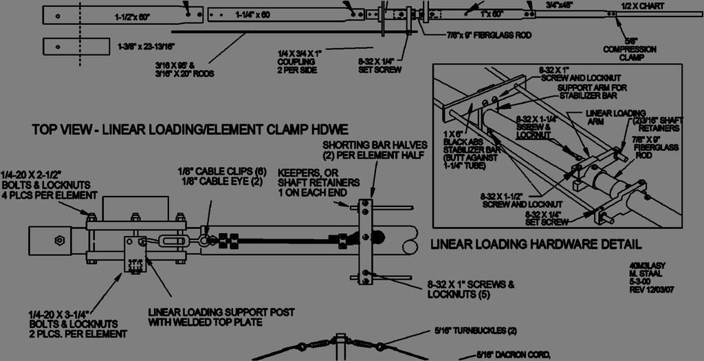
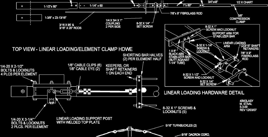
2 40M3L ASSEMBLY MANUAL BEFORE YOU BEGIN: Look over the DIMENSION SHEET, HARDWARE AND ELEMENT ASSEMBLY DRAWINGS to get familiar with the various parts of the antenna. Tools handy for assembly process: screwdriver, 11/32, 7/16, 1/2, 9/16 and 5/8 nut drivers, end wrenches and/or sockets, diagonal cutters, and measuring tape. Small containers of zinc paste (Penetrox, Noalox, or equiv.) has been provided to enhance and maintain the quality of all electrical junctions on this antenna. Apply a thin coat wherever two pieces of aluminum come in contact or any other electrical connections are made. 1. ELEMENT CLAMP BLOCK ASSEMBLY. SEE ELEMENT HARDWARE drawings to aid in the assembly of this step. Start by assembling pairs of ELEMENT CLAMP PLATES, #6 together with 1/4-20 x 2-1/2" bolts in the four outer holes. NOTE THAT ONE SET OF CLAMP PLATES WILL ALSO GET A 1 X 1 X 6 ANGLE BRACKET FOR MOUNTING THE BALUN. Add the 1/4-20 locknuts finger tight. A. DRIVEN ELEMENT On one of the element clamp plates assembled in the previous step, slip in the 1-1/4 X 24" fiberglass rod and rotate until the element mounting holes are vertical. Center the rod and tighten the hardware EVENLY, so the plates are parallel and the same amount of threads are showing through all the locknuts. Slide the POLYETHYLENE DISC INSULATORS onto both ends of the fiberglass rods and push them up against the clamp plates. The disc insulators can sometimes be a very tight fit on the rods. If you can t get them to fit, place them in hot water a few minutes. B. REFLECTOR, DIRECTOR ELEMENT Slide a 1-1/4 x 24 aluminum CENTER COUPLING ROD into a CLAMP PLATE ASSEMBLY. Center the assembly and align the bolt holes to vertical. Tighten all four outer element clamp plate bolts EVENLY. Make sure plates remain parallel, top to bottom. 2. VERTICAL SUPPORT POST INSTALLATION (OVERHEAD SUPPORT UPGRADE DRAWING). The element clamps require a 1 SQ. X 24 WELDED VERTICAL SUPPORT POST to raise and support the linear loading lines and complete element assembly. Orient the WELDED PLATE over the element clamp plates. 3. HALF ELEMENT ASSEMBLIES There are 6 half element assemblies. One pair each for the Reflector, Driven Element and Director Element. See the ELEMENT ASSEMBLY drawing to aid in the assembly of each half element. Also refer to the DIMENSION SHEET and ELEMENT HARDWARE DETAIL drawings. Only the 1/2 element tip sections are different lengths. The correct hardware to join the various sizes are as follows: For 1-1/2" to 1-1/4" tubing use 8-32 x 1-3/4" screws. For 1-1/4" to 1" tubing use 8-32 x 1-1/2" screws. For 1" to 1 and 1 to 3/4" tubing use 8-32 x 1-1/4" screws. For 3/4" to 1/2" tips use 5/8 compression clamps. Locknuts have been provided for all the element assembly screws. Tighten the nuts until the joint doesn't move when wiggled or shook. The element butt section closest to the boom always has one hole located at the butt for a 1/4-20 bolt. A. Prepare the LINEAR LOADING ARMS, (See linear loading detail drawing) 1 center hole with one 8-32 x 1/4 Allen head SET SCREW. (5/64 Allen wrench supplied), one 8-32 x 1-1/2 screw and locknut. Slide a LINEAR LOADING ARM on each 1" section and position it next to the end screw. Then slide the element overhead support clamp up against the 8-32 x 1-1/4 screws head nearest the end. Align it per the ELEMENT ASSEMBLY drawings & Linear loading detail and tighten the 8-32 hardware securely.
3 40M3L ASSEMBLY MANUAL B. Now slide the 1 tube sections over the 7/8 x 9 fiberglass rod insulators. Connect the two sections with 8-32 x 1-1/4" screws and locknuts. Orient the arms as shown and tighten the 8-32 x 1-1/2 screws and locknuts. Be sure the arms are up against the screws closest to the fiberglass rod. THIS IS IMPORTANT SINCE THE ARMS ARE USED FOR DIMENSIONING THE LINEAR LOADING SHORTING BAR POSITION LATER IN THE ASSEMBLY C. Locate the black plastic, 1 x 6 linear loading stabilizer bars. Attach them to the short 3/8 x 1-1/4 x 3 support arm with the 1 inch hole. Use 8-32 x 1 screws and locknuts. Slide these on the SHORT, one inch element sections and position about 3 in from the butt. Now attach the 1-1/4 x 60 element sections. Add the 8-32 x 1-1/2 screws and locknuts but do not tighten until the STABALIZER BAR AND ARM ASSEMBLY ARE IN THE FINAL POSITION. Orient the black stabalizer bar insulators perpendicular to the element coupling holes and the support arms. Secure with 8-32 x 1-1/2 screws and locknuts. Repeat for the other element halves. E. Insert the 3/4 x 48 sections into the swaged 1 sections and secure with 8-32 x 1-1/4 screws and locknuts. F. Following the DIMENSION SHEET and COMPRESSION CLAMP & TIP ASSEMBLY DETAIL SHEET add the 1/2 tip sections in pairs, noting that each element has different tip lengths. Secure with compression clamps. G. As the outer element sections are being assembled, label each assembly as REFLECTOR, DIRECTOR or DRIVEN, (according to the 1/2 tips) to avoid mix ups. 4. REFLECTOR AND DIRECTOR ASSEMBLY See ELEMENT HARDWARE drawing. Slide a 1-3/8 x 23-13/16" sleeve onto the 1-1/4 CENTER COUPLING ROD on the ELEMENT CLAMP ASSEMBLY, and align the 1/4 holes. Temporarily pin the sleeve as necessary. Carefully slide a 1-1/2 x 60 element section onto this assembly and align all holes. Insert a 1/4-20 x 2 bolt and tighten securely with 1/4-20 locknut. Repeat for the other element half. Now add the reflector element outer half element assembly completed in the previous step to the 1-1/2" sections using 8-32 x 1-3/4" screws and locknuts. Repeat for the other element halves. 5. DRIVEN ELEMENT ASSEMBLY See ELEMENT HARDWARE drawings. Slide a 1-3/8 x 23-13/16" sleeve onto each end of the two 1-1/4 fiberglass rods of the remaining element clamp assemblies and align the 1/4 holes. Carefully slide a 1-1/2 x 60 element section onto the two assemblies and align all holes. For both, insert a 1/4-20 x 2 bolt and secure with 1/4-20 locknuts. BESURE TO INSTALL THE ELEMENT CLAMP PLATE ASSEMBLY WITH THE BALUN ANGLE BRACKET. 6. LINEAR LOADING ASSEMBLY SEE ASSEMBLY DRAWINGS A. Install a pair of LINEAR LOADING RODS to each element half. Insert a rod through each STABILIZER INSULATOR BAR and then through a LINEAR LOADING ARM, allowing about 3/4" to extend beyond the arm. Install 8-32 x 1/4" Allen head screws to lock rods in place and add 3/16 shaft retainers for extra safety. B. Loosely assemble the LINEAR LOADING CLAMP PLATES (SHORTING BAR) pairs using 8-32 x 7/8 screws and locknuts. C. Slide one set of these shorting bars on the ends of the 3/16 linear loading rods. Measure and mark the position for the shorting bars. Move the bars to that location and tighten one screw to hold position. Insert a short section of BLACK PHILISTRAN CABLE (HPTG1200) through one hole, around strain relief and back thru other hole of shorting bar then add 3/16 cable clip to secure it.
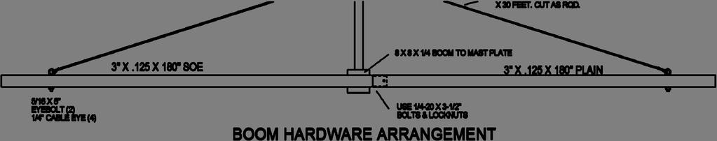
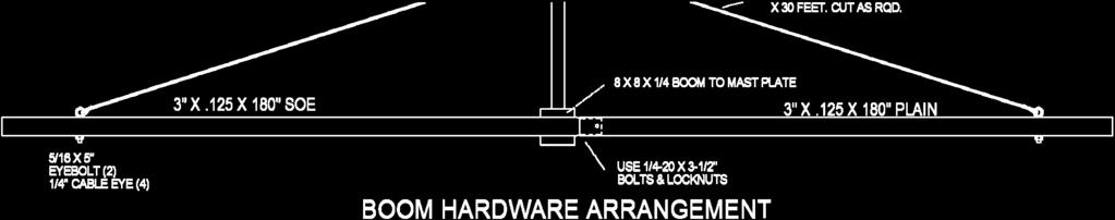
4 40M3L ASSEMBLY MANUAL D. Alight the rods and begin to tighten all the 8-32 x 7/8 screws and locknuts. Be sure the rods are parallel and have the same tension. Complete tightening the screws. Repeat for all the element halves. E. Place the element on a level surface with support post "up." F. Prepare the 1/4 HOOK AND EYE TURNBUCKLES by removing the hook end and running a 1/4-20 plain nut all the way to the hook. Now replace the hook end into the turnbuckle body and thread it in until just one thread shows inside the body of the turnbuckle. Now adjust the other end EYE of the turnbuckle until just one thread show inside the body. G. Install the 1/4" HOOK AND EYE TURNBUCKLES in the welded plates at the middle and at the top of the ELEMENT SUPPORTS. Install a CABLE EYE in the EYE of each turnbuckle and route the BLACK HPTG-1200 Philistran cable through the eye and back on itself. Review the element over head support detail drawings for proper routing of the BLACK PHILISTRAN CABLE (HPTG1200) to lock the cable to the clamp. Tension the element overhead support line and linear loading assembly and secure the cable with two cable clips on each line as shown. Repeat for remaining elements. H. Now adjust the turnbuckles, adjusting so the inner sections are level and tighten the turnbuckle jam nuts. Element tips should droop about 4" to 8". The element will be more stable in the wind if you allow some droop to remain in the element. Inspect each element for tight hardware and balanced tension on linear loading rods and element assembly supports. Minor tensioning adjustments can be accomplished using the turnbuckles. 7. BOOM ASSEMBLY Use the BOOM HARDWARE drawing as a guide to assemble the boom. At this point it will be helpful to perform the remaining assembly steps with the antenna elevated off the ground (about 3 feet). This can be accomplished by using sawhorses or something similar. Wipe off the swaged ends of each boom section and apply a small amount of Penetrox. Insert the swaged end of the boom sections into the straight piece. Align all of the holes, install the 1/4-20 x 3-1/2" bolts and locknuts, and tighten. A. Install the 5/16 EYEBOLTS to the outer ends of the boom, securing with stainless 5/16 nuts and lock washers. Align the eyes parallel with the boom and tighten. 8. Orient the boom with the eyebolts "up. Note the location of the REAR end of the antenna and parasitic elements as shown on the DIMENSION SHEET. Using a tape measure and a marking pen or masking tape, place a mark 1/2 in from the rear of the boom. This will be where you position the back edge of the clamp plate for the reflector element. Repeat the same procedure for the other three elements. 9. For ease of element installation, support the boom about 3 above ground, eyebolts "up." Place the reflector element on the boom. Loosely attach two BOTTOM CRADLES to the bottom of the clamp plates ON THE REFLECTOR AND DIRECTOR using the 1/4-20 x 2-3/4" bolts. (BE SURE TO USE ZINC PASTE ON THESE THREADS) Slide the back edge of the rear plate to your first mark. Level the reflector element and tighten all four bolts EVENLY and firmly. Repeat for the DIRECTOR on the other end of the boom.
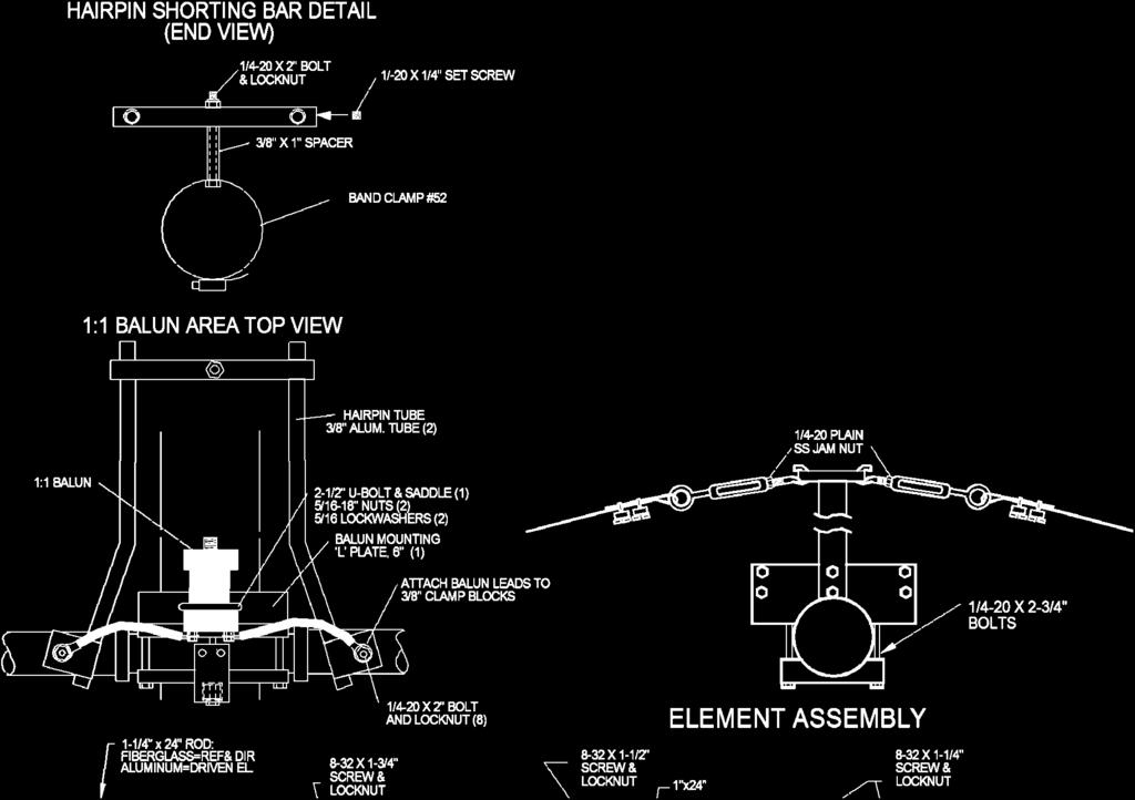
5 40M3L ASSEMBLY MANUAL 10. Mount the DRIVEN ELEMENT assembly in it s respective position, then attach the two bottom cradles and 1/4-20 hardware. After aligning with the reflector element, tighten the 1/4-20 bolts evenly and firmly. 11. Now take a step back for a moment to observe any misalignment (if any) and the droop in each element. Simply look down either the front or back of the boom to do this. If you have not already done so, adjust each turnbuckle until each element droops 6 to 10 inches at the tip. NOTE: The elements are the most stable in wind with a small amount of tip droop. ADJUST FOR LEVEL INNER SECTIONS. After the adjustments have been made, proceed with tightening the 1/4-20 JAMNUT on all the turnbuckles :1 HF BALUN INSTALLATION SEE ASSEMBLY DRAWINGS AND DIMENSION SHEET Mount the balun to the angle plate on the driven element using a 2-1/2 U-bolt and saddle. Be sure the balun vent hole is down. Do not over tighten as balun damage may occur. 13. INSTALLING THE HAIRPIN (MATCHING ASSEMBLY) A. Apply a little Penetrox to the balun terminal lugs. Remove the nuts holding the 3/8 clamp blocks and place the balun lead lugs over the studs. Replace the nuts loosely. Apply a little Penetrox to the shorter bent ends of the hairpin tubes. INSERT the tubes into the grooved channels of 3/8 clamp block assemblies on Driven element. Push the tubes through until at least 1/4" extends beyond clamp and then tighten the clamp bolt slightly to hold the tubes from slipping. Rotate the tubes so the bends are level and the long sections are parallel to the boom. B. Install the 1/4-20 x 1/4 set screws into the ends of the HAIRPIN SHORTING BAR. Insert a 1/4-20 x 2 bolt into the hole of the #52 stainless band clamp from the inside and add the 3/8 x 1 aluminum spacer. Add the shorting bar and the lock nut loosely to hold the assembly together. Open the clamp and set it over the boom about 60 inches from the driven element. Now slide the assembly to the ends of the hairpin tubes and insert the end into the shorting bar. ( lubricant like WD-40 or zinc paste will let the shorting bar slide easier on the tubes. Position the shorting bar 38 inches from the driven element. Align the assembly, and tighten the band clamp. Next tighten the nut securing the shorting bar and finally tighten the set screws onto the tube. NOTE: IF YOU CAN DO FINAL VSWR MEASURMENTS AND ADJUSTMENTS DURING THE FINAL INSTALLATION, DO NOT TIGHTEN THE SET SCREWS YET. SEE THE NOTE AT THE BOTTOM OF THE DIMENSION SHEET C. Now return the to balun end of the hairpin assembly and final tighten the bolts holding the tube ends and the balun leads. 14. Attach the BOOM TO MAST PLATE at the balance point, using the two large 3 U-bolts, 3/8-16 stainless lockwashers, and nuts. Align plate to vertical and tighten nuts. For they should be attached in a way to allow the boom to be balanced on your tower / mast. 15. OVERHEAD BOOM SUPPORT SYSTEM. A. Attach one end of the 5/16" Dacron cord to the rear eyebolt using two turns around the eyebolt and a series of three half hitches or equivalent knots. Finish with about 6 inches of cord after the knots. Without cutting the cord, do the same at the front eyebolt. Pull on the knots HARD to SET them. Seal ends with heat or flame to prevent fraying. Tape the excess 6 inches of cord back to main cord tightly with black vinyl electricians tape.
6 40M3L ASSEMBLY MANUAL B. TEMPORARILY insert a 2 inch U-bolt through the turnbuckle plate and add two nuts so about 1/2 inch of the threads stick out. Insert this assembly through the top set of 2 U-bolt holes in the boom to mast plate from the boom side and add two more nuts. Open the two turnbuckles up until just a thread or two from each end shows inside the body of the turnbuckle. Hook the turnbuckles into the holes at the edge of the turnbuckle plate. Equalize the Dacron cord over the plate and cut it. Take two wraps of the cord through the eye of the rear turnbuckle, PULL the cord as tight as possible and make the knots as before. Repeat for the front cord section and turnbuckle. Cut off any excess over one foot long and again seal and tape back to the main cord. C. Now DISASSEMBLE the U-bolt from the boom to mast plate. Before installation, if possible, install a short temporary mast, attach turnbuckle, and let the overhead guy system support the boom overnight. The Dacron cord DOES NOT STRETCH UNDER THIS LOAD but it's weave will take a SET and the boom may droop just a bit. If your boom droops again following final adjustments, check your knots. They may be may be slipping. D. After final installation of the antenna, the turnbuckle plate, installed loosely with a 2 U-bolt, is raised up the mast. When the boom is straight the U-bolt is tightened. This should place the turnbuckle plate 4 to 6 feet above the boom. Do the final boom straightening with the turnbuckles and safety wire to preserve adjustments. 16. Check ALL hardware for tightness. Check ALL element sections, especially tip sections, for correct placement. Make any final adjustments to linear loading tension. 17. Attach the feedline section to the balun. Route it towards the boom to mast plate. Secure at regular intervals with tape or nylon ties. 18. When mounting this antenna on a tower or mast with other antennas there may be interaction. In general VHF and/ or UHF antennas mounted for HORIZONTAL POLARITY should be AT LEAST 40 inches above or below the antenna. Use good quality 50 Ohm coaxial cable to feed the antenna and be sure your tower and rotator system can handle the wind loading and vertical weight of this antenna. THIS COMPLETES ANTENNA ASSEMBLY M 2 ANTENNA SYSTEMS, INC N. SELLAND AVE. FRESNO, CA (559) FAX (559) sales@m2inc.com

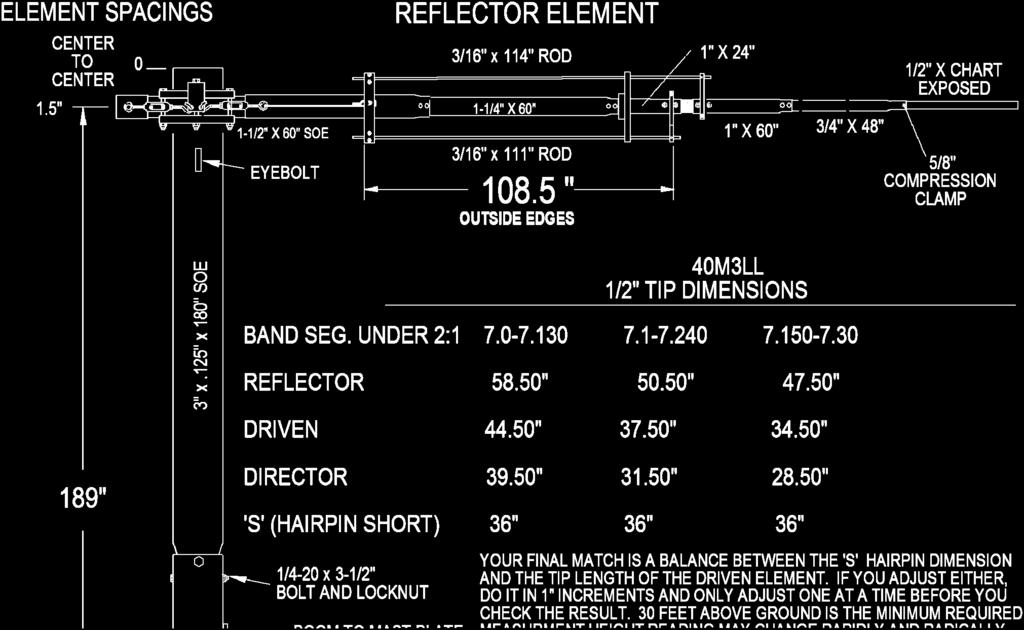
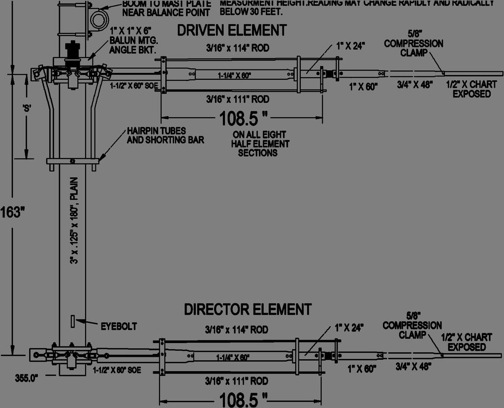
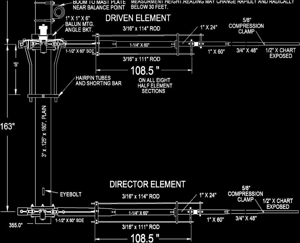
7 40M3L DIMENSION SHEET

8 2M4 ASSEMBLY MANUAL OVERHEAD SUPPORT UPGARDE DETAIL


9 ELEMENT OVERHEAD SUPPORT CLAMP 2M4 ASSEMBLY MANUAL LINEAR LOADING DETAIL
10 40M3L ASSEMBLY DETAIL

11 40M3L ASSEMBLY DETAIL

12 GENERIC COMPRESSION CLAMP DETAIL
13 40M3L PARTS & HARDWARE UNBAGED ITEMS DESCRIPTION... QTY Assembly manual... 1 Insulator, 1-1/4 x 24" fiberglass rod... 1 Coupling, center 1-1/4 x 24 alum. Rod Boom to mast plate, 1/4 x 8 x 8" alum Balun, 1:1, 3-30 MHz SO-239 conn Tension Line, Phyllistrand 1200 HTPG, Support post, 1 x 1 x 24 SQ. Tube (M2AVR0050)... 3 Element Overhead Support, HPTG1200 x Zinc Paste ( Penetrox, Noalox or equivalent) container... 1 Dacron cord, 5/16 x 30 feet... 1 ALUMINUM TUBING DESCRIPTION... QTY Boom section, 3 x.125 x 180" SOE (Drilled both ends)... 1 Boom section, 3 x.125 x 180" STR... 1 Sleeve, 1-3/8 x.058 x 23-13/16"... 6 Element butt section, 1-1/2 x.058 x 60" SOE... 6 Element section, 1-1/4 x.058 x 60 SOE... 6 Element section, 1.0 x.058 x 60 SOE... 6 Element section, 1.0 x.058 x 24 SOE... 6 Element section, 3/4 x.049 x 48" SOE... 6 Element tip section, 1/2 x.049 x Element tip section, 1/2 x.049 x Element tip section, 1/2 x.049 x Hair pin tube, 3/8 x ALUMINUM ROD DESCRIPTION... QTY Linear loading rod 3/16 x 114" alum Linear loading rod, 3/16 x 111" alum BAG #1 Linear loading arm, 3/8 x 1-1/4 x 3-3/4, alum. 1 hole Element Overhead Support Clamp, 3/8 x 3 3/ BAG #2 Insulator, stabilizer bar, 1/4 x 1 x 6 ABS Support arm, for stabilizer bar 3/8 x 1-1/4 x 2-7/8, alum. 1 hole... 6 BAG #3 Disc insulator, 3/8 x 2" polyethylene, 1-1/4" hole... 2 Clamp Block, hairpin, 1/4 x 1-1/4 x 1 alum., 3/8 groove... 4 Balun mounting angle bracket, 1 x 1 x 6 alum Band clamp, #52 with hole... 1 Turnbuckle plate 3/16 x 2 x 5, alum Turnbuckle, 1/4-20 x 6, hook and eye Turnbuckle, 5/16 hook and eye... 2 Eyebolt, 5/16 x 5 # Cable eye, 1/ Nylon ties, Spacer, 3/8 x 1 ( used in hairpin assembly)... 1
14 40M3L PARTS & HARDWARE BAG #4 Shorting bar, 1/4 x 3/4 x 6" Strain Relief, 1/2 x 1/2 blk delrin... 6 Shorting bar, hairpin, 1/2 x 1/2 x BAG #5 Saddle Clamp, 1/2 x 1.0 x 4" alum Element Clamp plate, 1/2 x 3 x 6", 5/8 radius, alum # BAG #6 Fiberglass rod, 7/8 x 9 with 4 holes... 6 BAG #7 U-bolt, 3"... 2 U-bolt, 2-1/2"... 1 U-bolt, 2", HEAVY DUTY... 4 U-bolt, 2 standard... 1 BAG #8 Nut, 3/8-16 stainless Lock washer, 3/8" split ring stainless Nut, 5/16-18, stainless... 6 Lock washer, 5/16" split ring, stainless... 4 Bolt, 1/4-20 x 3-1/2" stainless... 8 Bolt, 1/4-20 x 3-1/4 stainless... 6 Bolt, 1/4-20 x 2-3/4" stainless Bolt, 1/4-20 x 2-1/2" stainless Bolt, 1/4-20 x 2.0" stainless... 5 Set screws, 1/4-20 x 1/4,ss... 2 Nut, 1/4-20, stainless... 6 Nut, 1/4-20 locking, stainless Allen wrench, 1/ BAG #9 5/8 Compression clamp... 6 Screw, 8-32 x 1-3/4 panhead, stainless Screw, 8-32 x 1-1/2" panhead, stainless Screw, 8-32 x 1-1/4" panhead, stainless Screw, 8-32 x 1.0" panhead, stainless Screw, 8-32 x 1/2" panhead, stainless... 6 Set screw, 8-32 x 1/4 stainless Nut, 8-32, stainless... 6 Nut, 8-32 locking, stainless Shaft retainer, 3/16 stainless Push tube 3/8 x 3" alum Allen wrench 5/ Cable Clips, 1/ Small Cable Eyes, 1/ M 2 ANTENNA SYSTEMS, INC N. SELLAND AVE. FRESNO, CA (559) FAX (559) sales@m2inc.com
M2 Antenna Systems, Inc. Model No: 20M5LD
 M2 Antenna Systems, Inc. Model No: 20M5LD SPECIFICATIONS: Model... 20M5LD Frequency Range... 14.0 14.350 MHz *Gain (Full Band)... 10.2 dbi Typical Front to back... 23 db Typical Beamwidth... E=50 / H=66
M2 Antenna Systems, Inc. Model No: 40M2L
 M2 Antenna Systems, Inc. Model No: 40M2L SPECIFICATIONS: Model...40M2L Frequency Range...6.9-10 MHz X 150 khz Gain...5.5 dbi Front to back...13 15 db Beamwidth...E=74 Feed type...hair pin match Feed Impedance....50
M2 Antenna Systems, Inc. Model No: 20M6-125
 M2 Antenna Systems, Inc. Model No: 20M6-125 SPECIFICATIONS: Model... 20M6-125 Frequency Range... 14.0 14.350 MHz *Gain, (FS) / Over gnd... 11.19dBi / 16.6dBi @70 Front to back... 25 db Typical Beamwidth...
M2 Antenna Systems, Inc. Model No: 10-30LP8
 M2 Antenna Systems, Inc. Model No: 10-30LP8 SPECIFICATIONS: Model... 10-30LP8 Frequency Range... 10-30 MHz Continuous *Gain free space / 65... 5.2 dbi / 10.5 dbi 10-30 Front to back... 15 db 10-30 MHz
M2 Antenna Systems, Inc. Model No: 10-30LP8
 M2 Antenna Systems, Inc. Model No: 10-30LP8 VSWR 2:1 TYPICAL VSWR @ 70 FT. 2:1 1.5:1 1.5:1 1.2:1 1.2:1 10 14 MHz 11 12 13 17 15 16 18 19 20 21 22 23 24 25 26 27 28 29 30 SPECIFICATIONS: Model...10-30LP8
M2 Antenna Systems, Inc. Model No: 10-30LP8-125
 M2 Antenna Systems, Inc. Model No: 10-30LP8-125 VSWR 2:1 TYPICAL VSWR @ 70 FT. 2:1 1.5:1 1.5:1 1.2:1 1.2:1 10 14 MHz 11 12 13 17 15 16 18 19 20 21 22 23 24 25 26 27 28 29 30 SPECIFICATIONS: Model...10-30LP8-125
M2 Antenna Systems, Inc. Model No: 7&10-30LP8
 M2 Antenna Systems, Inc. Model No: 7&10-30LP8 2:1 100KHz BANDWIDTH@ 1.8:1 VSWR 1.5:1 6.9 7.0 7.1 10 FREQUENCY (MHZ) 20 SPECIFICATIONS: Model...7&10-30LP8 Skip log Frequency Range...10-30 MHz Continuous
M2 Antenna Systems, Inc. Model No: 2M5WL
 M2 Antenna Systems, Inc. Model No: 2M5WL SPECIFICATIONS: Model... 2M5WL Frequency Range... 144 To 148 MHz *Gain... 16.84 dbi Front to back... 22 db Typical Beamwidth... E=26 H=29 Feed type... T Match Feed
M2 Antenna Systems, Inc. Model No: 2M7
 M2 Antenna Systems, Inc. Model No: 2M7 SPECIFICATIONS: Model... 2M7 Frequency Range... 144 To 148 MHz *Gain... 12.3 dbi Front to back... 20 db Typical Beamwidth... E=43 H=50 Feed type... T Match Feed Impedance....
M2 Antenna Systems, Inc. Model No: 2M4
 M2 Antenna Systems, Inc. Model No: 2M4 SPECIFICATIONS: Model... 2M4 Frequency Range... 144 To 148 MHz *Gain... 9.6 dbi Front to back... 20 db Typical Beamwidth... E=54 H=74 Feed type... T Match Feed Impedance....
M2 Antenna Systems, Inc. Model No: 450CP34
 M2 Antenna Systems, Inc. Model No: 450CP34 SPECIFICATIONS: Model... 450CP34 Frequency Range... 435 To 455 mhz *Gain... 16.0 dbi Front to back... 22 db Typical Beamwidth... 28 Circular Feed type... T Match
M2 Antenna Systems, Inc. Model No: 2MCP22
 M2 Antenna Systems, Inc. Model No: 2MCP22 SPECIFICATIONS: Model... 2MCP22 Frequency Range... 144 To 148 MHz *Gain... 14.39 dbic Front to back... 25 db Typical Elipticity... >3db Beamwidth... 38 Feed type...
M2 Antenna Systems, Inc. Model No: YAGI ANTENNA
 M Antenna Systems, Inc. Model No: 4.5-7 YAGI ANTENNA SPECIFICATIONS: Model... 4.5-7 Frequency Range... 4.0 To 4.5 MHz *Gain... 0 To 7 dbi Front to back... 0 db over the rear 80 Beamwidth... E=44 H=50 typical
M2 Antenna Systems, Inc. Model No: 450CP26
 M2 Antenna Systems, Inc. Model No: 450CP26 SPECIFICATIONS: Model... 450CP26 Frequency Range... 445 To 455 mhz *Gain... 16.5 dbi Front to back... 21 db Typical Beamwidth... 30 Circular Feed type... T Match
M2 Antenna Systems, Inc. Model No: 436CP30
 M2 Antenna Systems, Inc. Model No: 436CP30 SPECIFICATIONS: Model... 436CP30 Frequency Range... 432 To 440 MHz *Gain... 15.50 dbic Front to back... 18 db Typical Elipticity... 1.5 db Typical Beamwidth...
M2 Antenna Systems, Inc. Model No: 456CP34
 M2 Antenna Systems, Inc. Model No: 456CP34 SPECIFICATIONS: Model... 456CP34 Frequency Range... 435 To 470 mhz *Gain... 16.0 dbi Front to back... 23 db Typical Beamwidth... 30 Circular Feed type... T Match
M2 Antenna Systems, Inc. Model No: KT31WARC
 M2 Antenna Systems, Inc. Model No: KT31WARC SPECIFICATIONS: Model... KT31WARC Frequency Range... 10.1-10.15 MHz **Selectable Frequency Range... 14.0-14.35 MHz **Selectable... (175 KHz / 2:1 VSWR Nominal)
M2 Antenna Systems, Inc. Model No: 6M8GJ
 M2 Antenna Systems, Inc. Model No: 6M8GJ SPECIFICATIONS: Model... 6M8GJ Frequency Range... 50.0 To 50.4 mhz *Gain, (FS) / Over gnd... 14.2 dbi / 19 dbi @ 20 Front to back... 20 db Typical Beamwidth...
THIS SHOULD TWEAK YOUR IMAGINATION
 10-27-05 THIS SHOULD TWEAK YOUR IMAGINATION SPECIFICATIONS FOR SINGLE ANTENNA MODEL NUMBER... 432EME-12 FREQUENCY... 430-436 MHz GAIN... 14.4 dbd FRONT TO BACK... 23 db VSWR... 1.2:1 TYPICAL BEAMWIDTH...
M2 Antenna Systems, Inc. Model No: 435XP50
 M2 Antenna Systems, Inc. Model No: 435XP50 SPECIFICATIONS: Model... 435XP50 Frequency Range... 430 To 436 MHz *Gain... 19.2 dbi Front to back... 22 db Typical Cross pol. isolation... >20 db Typical Beamwidth...
M2 Antenna Systems, Inc. Model No:
 M2 Antenna Systems, Inc. Model No: 400-600-10 SPECIFICATIONS: Model... 400-600-10 Frequency Range... 390 To 650 MHz *Gain... 12 To 13 dbic Front to back... 20 db Nominal Beamwidth... 46 Nominal Feed Impedance....
M2 Antenna Systems, Inc. Model No: HFTB2MXP X2-1K
 M2 Antenna Systems, Inc. Model No: HFTB2MXP28-32-2X2-1K FRONT OF SYSTEM REAR OF SYSTEM SPECIFICATIONS: Model... HFTB2MXP28-32-2X2-1K Band... 2M Antenna... 2MXP28-32 T-Brace... Y Cross Boom Dia... 3.0 Wind
M2 Antenna Systems, Inc. Model No: FGHFTB2MXP202X2
 M2 Antenna Systems, Inc. Model No: FGHFTB2MXP202X2 FRONT OF SYSTEM REAR OF SYSTEM SPECIFICATIONS: Model... HFTB2MXP20-2X2 Band... 2M Antenna... 2MXP20 T-Brace... Y Cross Boom Dia... 3.0 Wind Load w/o Ant.....
M2 Antenna Systems, Inc. Model No: HFTB2MXP X2-3K
 M2 Antenna Systems, Inc. Model No: HFTB2MXP28-32-2X2-3K FRONT OF SYSTEM REAR OF SYSTEM SPECIFICATIONS: Model... HFTB2MXP28-32-2X2-3K Band... 2M Antenna... 2MXP28-32 T-Brace... Y Cross Boom Dia... 3.0 Wind
M2 Antenna Systems, Inc. Model No: HFTB6MXP20-2X2
 M2 Antenna Systems, Inc. Model No: HFTB6MXP20-2X2 FRONT OF SYSTEM REAR OF SYSTEM SPECIFICATIONS: Model... HFTB6MXP20-2X2 Band... 6M Antenna... 6MXP20 T-Brace... Y Cross Boom Dia... 4.5 Wind Load w/o Ant.....
M2 Antenna Systems, Inc. Model No: KT34XA TO KT36XA UPGRADE KIT
 M2 Antenna Systems, Inc. Model No: KT34XA TO KT36XA UPGRADE KIT SPECIFICATIONS: SPECIFICATIONS for the KT34-6XA MODEL NUMBER...KT36XA FREQ. RANGE...14.0-14.35 MHz 21.0-21.45 MHz 28.0-29.0 MHz GAIN (Free
M2 Antenna Systems, Inc. Model No: 2M HO LOOP
 M2 Antenna Systems, Inc. Model No: 2M HO LOOP SPECIFICATIONS: Model... 2M HO LOOP Frequency Range... 144 To 144.5 MHz Gain, Typical @ 10 ft.... 4 dbd @ 10 deg. Gain, 2 STK @ 82 & 132... 8 dbd @ 9 deg.
Directive Systems & Engineering 2702 Rodgers Terrace Haymarket, VA
 Directive Systems & Engineering 2702 Rodgers Terrace Haymarket, VA 20169 1628 www.directivesystems.com 703 754 3876 K1JX DESIGNED 6 ELEMENT 50 MHZ YAGI, DSEJX6 50 INTRODUCTION The Directive Systems DSEJX6-50
K1FO 12 ELEMENT 144/147 MHz YAGI
 K1FO 12 ELEMENT 144/147 MHz YAGI WARNING: INSTALLATION OF THIS PRODUCT NEAR POWER LINES IS DANGEROUS. FOR YOUR SAFETY FOLLOW THE INSTALLATION DIRECTIONS. Ariane Arrays, Inc. Copyright 2006 201 Hopedale
Assembly Instructions: Bencher Skylark
 Assembly Instructions: Bencher Skylark Tools Required: Pop Rivet Tool Tape Measure Hex Wrenches Screwdriver Several Disposable Rags Two Saw Horses Several boxes or bowls to hold fasteners and small parts
INSTRUCTION MANUAL. Specifications Electrical. Front-To-Back Ratio VSWR at Resonance Less than 1.5:1 Nominal Impedance. Mechanical
 300 Industrial Park Road, Starkville, MS 39759 Ph: (662) 323-8538 FAX: (662) 323-6551 TH-3JRS Tri-band HF 3 Elements Beam Covers 10, 15 and 20 Meters INSTRUCTION MANUAL WARNING Installation of this product
Model VB-23FM 2-Meter 3-Element Beam
 308 Industrial Park Road Starkville, MS 39759 USA Ph: (662) 323-9538 FAX: (662) Model VB-23FM 2-Meter 3-Element Beam [ INSTRUCTION MANUAL Figure 1 Overall View and Boom Detail GENERAL DESCRIPTION This
INSTRUCTION MANUAL. Specifications Mechanical. 1 5/8 to 2 1/16 O.D. (41mm to 52mm)
") 308 Industrial Park Road Starkville, MS 39759 USA Ph: (662) 323-9538 FAX: (662) 323- General Description Model VB-25FM 2-Meter 5 Elements Beam INSTRUCTION MANUAL This antenna is a 5-element, 2-meter beam
308 Industrial Park Road Starkville, MS 39759 USA Ph: (662) 323-9538 FAX: (662) 323- General Description Model VB-25FM 2-Meter 5 Elements Beam INSTRUCTION MANUAL This antenna is a 5-element, 2-meter beam
MODEL DB-1015A 10- and 15-Meter Duo-Band Antenna Order No. 330
 MODEL DB-1015A 10- and 15-Meter Duo-Band Antenna Order No. 330 HY-GAIN ELECTRONICS CORPORATION 8601 Northeast Highway 6 Lincoln, Nebraska 68505 Telephone 464-9151 Area Code 402 TABLE OF CONTENTS page SECTION
TZ-RD-1740 Rotary Dipole Instruction Manual
 TZ-RD-1740 17/40m Rotary Dipole Instruction Manual The TZ-RD-1740 is a loaded dipole antenna for the 40m band and a full size rotary dipole for the 17m band. The antenna uses an aluminium radiating section
INSTRUCTION MANUAL. Model VB-215DX MECHANICAL DESIGN GENERAL DESCRIPTION ELECTRICAL DESIGN. 2 Meter 15 Element Yagi for SSB/CW
 Model VB-215DX 2 Meter 15 Element Yagi for SSB/CW INSTRUCTION MANUAL GENERAL DESCRIPTION The Hy-Gain Model 215DX is a high performance yagi antenna for SSB/CW DXing in the Amateur 2 meter band. It features
Cushcraft. Amateur Radio Antennas LFA-6M5EL. 6 Meter 5 Element Loop Feed Antenna INSTRUCTION MANUAL
 Cushcraft Amateur Radio Antennas LFA-6M5EL 6 Meter 5 Element Loop Feed Antenna INSTRUCTION MANUAL CAUTION: Read All Instructions Before Operating Equipment VERSION 1A Cushcraft Amateur Radio Antennas 308
INSTRUCTION MANUAL ORDER NO. V3R MODEL V3R. Collinear Gain Vertical for MHz
 ORDER NO. V3R MODEL V3R Collinear Gain Vertical for 216-225 MHz INSTRUCTION MANUAL General Description The new Hy-Gain V3R VHF antenna is a collinear 5/8-wave omnidirectional vertical antenna for the 216-225
JK-65 Five Element 6M Yagi
 JK-65 Five Element 6M Yagi PO Box 266, Croton Falls, NY 10519-0266 845.228.8700 (TEL) 845.279.5526 (FAX) info@jkantennas.com Page 1 of 8 JK Antennas Limited Warranty and Liability JK Antennas ( Manufacturer
INSTRUCTION MANUAL for MODEL TH6-DX "THUNDERBIRD" (389)
") INSTRUCTION MANUAL for MODEL TH6-DX "THUNDERBIRD" (389) HY-GAIN ELECTRONICS CORPORATION, N. E. Hwy #6 at Stevens Creek, Lincoln, Nebraska 65801 Telephone 434-6331 INTRODUCTION Ely-Gain's new Model TH6-DX
INSTRUCTION MANUAL for MODEL TH6-DX "THUNDERBIRD" (389) HY-GAIN ELECTRONICS CORPORATION, N. E. Hwy #6 at Stevens Creek, Lincoln, Nebraska 65801 Telephone 434-6331 INTRODUCTION Ely-Gain's new Model TH6-DX
INSTRUCTION MANUAL V-42R. Dual Band Collinear Gain Vertical for MHz and GENERAL DESCRIPTION
 308 Industrial Park Road, Starkville, MS 39759 USA Ph: (662) 323-9538 FAX: (662) 323-6551 V-42R Dual Band Collinear Gain Vertical for 144-148 MHz and 436-450 INSTRUCTION MANUAL GENERAL DESCRIPTION The
JK-404 GRANDE Four Element Full Size 40M Yagi
 JK-404 GRANDE Four Element Full Size 40M Yagi PO Box 266, Croton Falls, NY 10519-0266 845.228.8700 (TEL) 845.279.5526 (FAX) info@jkantennas.com JK Antennas Limited Warranty and Liability JK Antennas (
TELEX, liutiiilio"i TELEX COMMUNICATIONS, INC ALDRICH AVE. SO. MINNEAPOLIS. MN USA
 TELEX, liutiiilio"i TELEX COMMUNICATIONS, INC. 9600 ALDRICH AVE. SO. MINNEAPOLIS. MN 55420 USA INSTRUCTION MANUAL ORDER NO. 410 General This antenna is a five-element, Citizens Band beam with a forward
Directive Systems & Engineering 2702 Rodgers Terrace Haymarket, VA
 Directive Systems & Engineering 2702 Rodgers Terrace Haymarket, VA 20169-1628 www.directivesystems.com 703-754-3876 25 Element 7.4 wl. K1FO Designed Yagi, Model DSEFO432-25 ELECTRICAL SPECIFICATIONS Frequency
Cushcraft. Amateur Radio Antennas DB-46M8EL. Dual band 6 and 4 Meter, 8 Element Beam Antenna INSTRUCTION MANUAL
 Cushcraft Amateur Radio Antennas DB-46M8EL Dual band 6 and 4 Meter, 8 Element Beam Antenna INSTRUCTION MANUAL CAUTION: Read All Instructions Before Operating Equipment VERSION 1B Cushcraft Amateur Radio
400A 40113V, 401A 40120V, & 401AL 40120VL ALUMINUM VERTICAL 4000 LB LIFT INCLUDES SCREW LEG ASSEMBLY INSTRUCTIONS
 12/11/07 PAGE 1 OF 12 400A 40113V, 401A 40120V, & 401AL 40120VL ALUMINUM VERTICAL 4000 LB LIFT INCLUDES SCREW LEG ASSEMBLY INSTRUCTIONS Thank you for purchasing our product! *Please read these instructions
MI: (Secure this number someplace, for possible future need) SPECIFICATIONS:
 SPECIFICATIONS:") 6C ASSEMBLY INSTRUCTIONS ANTENNA MODEL T6 MI: 030927 (Secure this number someplace, for possible future need) SPECIFICATIONS: FORWARD GAIN 5.1 dbd F:B RATIO 15-25 db (Rises with frequency) FREQUENCY COVERAGE
6C ASSEMBLY INSTRUCTIONS ANTENNA MODEL T6 MI: 030927 (Secure this number someplace, for possible future need) SPECIFICATIONS: FORWARD GAIN 5.1 dbd F:B RATIO 15-25 db (Rises with frequency) FREQUENCY COVERAGE
LJ element beam for 10 or 12 meters INSTRUCTION MANUAL. CAUTION: Read All Instructions Before Operating Equipment
 LJ-113 3 element beam for 10 or 1 meters INSTRUCTION MANUAL CAUTION: Read All Instructions Before Operating Equipment 308 Industrial Park Road Starkville, MS 39759 USA Tel: 66-33-9538 Fax: 66-33-6551 VERSION
00108/00110 INSTRUCTION MANUAL
 00108/00110 INSTRUCTION MANUAL Removable and Adjustable Mudflap System IMPORTANT! Exhaust Systems Note: Any modifications to the factory installed exhaust system may void your manufacturer s warranty.
DB Duo-Monoband Beam 7 - Element, 12 and 17 Meter INSTRUCTION MANUAL. General Description
 308 Industrial Park Road Starkville, MS 39759 USA Ph: (662) 323-9538 FAX: (662) 323-6551 DB- 1217 Duo-Monoband Beam 7 - Element, 12 and 17 Meter INSTRUCTION MANUAL General Description The Hy-Gain DB-1217
JK BigTri. 3-Band Yagi (20M/15M/10M) 36Ft Boom
 36Ft Boom") JK BigTri 3-Band Yagi (20M/15M/10M) 36Ft Boom 72 Grays Bridge Road, Unit D, Brookfield, CT 06804 845.228.8700 (TEL) 845.279.5526 (FAX) info@jkantennas.com UPDATED : FEB 2017 JK Antennas Limited Warranty
JK BigTri 3-Band Yagi (20M/15M/10M) 36Ft Boom 72 Grays Bridge Road, Unit D, Brookfield, CT 06804 845.228.8700 (TEL) 845.279.5526 (FAX) info@jkantennas.com UPDATED : FEB 2017 JK Antennas Limited Warranty
JK NAVASSA-5. 5-Band Yagi (20M/17M/15M/12M/10M) Optional 6M Add-on Kit Available
 Optional 6M Add-on Kit Available") JK NAVASSA-5 5-Band Yagi (20M/17M/15M/12M/10M) Optional 6M Add-on Kit Available 72 Grays Bridge Road, Unit D, Brookfield, CT 06804 845.228.8700 (TEL) 845.279.5526 (FAX) info@jkantennas.com Last Updated:
JK NAVASSA-5 5-Band Yagi (20M/17M/15M/12M/10M) Optional 6M Add-on Kit Available 72 Grays Bridge Road, Unit D, Brookfield, CT 06804 845.228.8700 (TEL) 845.279.5526 (FAX) info@jkantennas.com Last Updated:
INSTRUCTION MANUAL VB-66DX. 6-Meter 6-Element Beam. Preparation For Assembly. General Description
 VB-66DX 308 Industrial Park Road Starkville, MS 39759 USA Ph: (662) 323-9538 FAX: (662) 323-6551 6-Meter 6-Element Beam INSTRUCTION MANUAL General Description The Hy-Gain Model 66DX is a full sized 6-
Hy-gain. Method 1 : Completely assemble the antenna on the ground then hoist it into position using a setup as shown in Figure 1.
 Hy-gain The Hy-Gain TH6-DXX "Super Thunderbird" is a 6-element beam designed to operate on 10, 25 and 20 meters. It has four active elements on 10-meters and three active elements on 15 and 20 meters.
JK M Hi-Q Coil Loaded Rotatable Dipole Version
 JK-401 40M Hi-Q Coil Loaded Rotatable Dipole 2018 Version 72 Grays Bridge Road, Unit D, Brookfield, CT 06804 845.228.8700 (TEL) 845.279.5526 (FAX) info@jkantennas.com LAST UPDATED: 02-01-2018 JK Antennas
HANDLING AND ASSEMBLY INSTRUCTIONS FOR TRUE FOCUS 3.0M, 3.8M AND 4.2M ANTENNAS WITH POLAR MOUNT
 HANDLING AND ASSEMBLY INSTRUCTIONS FOR TRUE FOCUS 3.0M, 3.8M AND 4.2M ANTENNAS WITH POLAR MOUNT Introduction SECTION 1 Thank you for purchasing one of our fine True Focus products. This manual covers the
REP Design LLC. 193 Winding Ridge Rd, Southington, CT INSTALLATION INSTRUCTIONS:
 REP Design LLC 193 Winding Ridge Rd, Southington, CT 06489 1-860.426.1894 n7emw@cox.net www.repdesign.us INSTALLATION INSTRUCTIONS: SHD-SO239 Super Heavy Duty SO-239Antenna Mounting System Thank you for
Kwik-Lock. Installation Instructions. Attention Dealers: Please give this owners manual to the customer when the product is delivered.
 Serving the Truck & Trailer Industry Since 1944 Installation Instructions Attention Dealers: Please give this owners manual to the customer when the product is delivered. Call 800-535-9545 www.aeroindustries.com
ASSEMBLING MANUAL LS 86. HF Log Periodic Antenna MHz
 ASSEMBLING MANUAL LS 86 HF Log Periodic Antenna 14 30 MHz ACOM LS86 HF Log-periodic Antenna ASSEMBLING MANUAL 1. GENERAL INFORMATION ACOM manufactures a range of antennas designed and produced to give
200A FLB VERTICAL 22113V LIFT W/CHAIN DRIVE WINCH
 PG. 1 OF 11 PORTA-DOCK, INC. 200A FLB VERTICAL 22113V LIFT W/CHAIN DRIVE WINCH STEP 1. Separate and group like parts and fasteners together. Locate the winch side member with the longer upright tube and
PAC-12 Kit Contents. Tools Needed Soldering iron Phillips screwdriver Wire stripper Wrenches, 7/16 and 1/2 Terminal crimp tool Pliers Solder
 PAC-2 Kit Contents Part Quantity Screws: 8/32 x 3/8 Screws: 8-32 x 5/6 Screw: 8-32 x /4 #8 internal tooth washers #8 solder lug ring terminals Bolt: Aluminum, /4-20 x.5 /4 internal tooth washer Nut: Aluminum
INSTRUCTION MANUAL. Model 18AVQII Five Band Vertical Antenna 10, 15, 20, 40, 80 Meter. General Description. Theory of Operation
 Model 18AVQII Five Band Vertical Antenna 10, 15, 20, 40, 80 Meter 308 Industrial Park Road Starkville, MS 39759 (662) 323-9538 Fax: (662) 323-5803 INSTRUCTION MANUAL General Description The Hy-Gain 18AVQII
HFp. User s Guide. Vertical. entenna. 7 MHz 30 MHz Amateur Radio Antenna Plus 6-Meters
 User s Guide HFp Vertical 7 MHz 30 MHz Amateur Radio Antenna Plus 6-Meters The Ventenna Co. LLC P.O. Box 2998, Citrus Heights, CA, 956 www.ventenna.com entenna Table of Contents The HFp Antenna -------------------------------------------------------------------
PowerLock. Installation Instructions. Attention Dealers: Please give this owners manual to the customer when the product is delivered.
 Serving the Truck & Trailer Industry Since 1944 FOR Attention Dealers: Please give this owners manual to the customer when the product is delivered. Call 800-535-9545 www.aeroindustries.com Indianapolis,
WARNING EXTREME CARE MUST BE USED FOR YOUR SAFETY
 WARNING EXTREME CARE MUST BE USED FOR YOUR SAFETY PLANNING Plan your installation carefully. If you use volunteer helpers be sure that they are qualified to assist you. Make certain that everyone involved
TELEX. iiilhiijiri INSTRUCTION MANUAL ORDER NO. 411 TELEX COMMUNICATIONS, INC ALDRICH AVE SO. MINNEAPOLIS. MN U.SA.
 TELEX. iiilhiijiri TELEX COMMUNICATIONS, INC. 9600 ALDRICH AVE SO. MINNEAPOLIS. MN 55420 U.SA. INSTRUCTION MANUAL ORDER NO. 411 Base Station, 5-Element Beam Antenna This antenna is a five element, Citizens
MFJ-1835K34 40,30 METER ADD ON KIT FOR THE MFJ-1835 COBWEB ANTENNA INSTRUCTION MANUAL. CAUTION: Read All Instructions Before Operating Equipment
 MFJ-1835K34 40,30 METER ADD ON KIT FOR THE MFJ-1835 COBWEB ANTENNA INSTRUCTION MANUAL CAUTION: Read All Instructions Before Operating Equipment 300 Industrial Park Road Starkville, MS 39759 USA Tel: 662-323-5869
MFJ-1846 Six-Band Hex-Beam Antenna
 MFJ-1846 Six-Band Hex-Beam Antenna Parts Inventory: As you unpack, please identify and check each part against the Master Parts List on the next page. This important step will familiarize you with the
RBP-1215B-RX DODGE RAM QUAD CAB RX3
 RBP-1215B-RX3 2002-2017 DODGE RAM 15-3500 QUAD CAB RX3 Passenger side RX-3 Side Step Drill Template Passenger side rear Modular Bracket (6) L Support Brackets Driver side rear Modular Bracket Driver side
Spiderbeam Balun Construction Guide
 BALUN CONSTRUCTION GUIDE Ver. 1.0 1 The components of the Balun Kit are in a plastic bag. Most of the components are inside the plastic case of the balun. The aluminum U-profile and the RG-142 Teflon Coax
Thank you for purchasing our product! *Please read these instructions and follow them step by step.*
 07/07/08.rev1 PAGE 1 OF 11 601AL VERTICAL 60120VL LIFT W/CHAIN DRIVE WINCH Thank you for purchasing our product! *Please read these instructions and follow them step by step.* Step 1. Separate and group
W6NL Moxon on Cushcraft XM240
 W6NL Moxon on Cushcraft XM240 0 db = 10.73 dbi 7.050 MHz 2.00 99.5% Efficiency High F/B 300+ khz VSWR BW SWR 1.50 1.00 7 7.1 7.2 7.3 MHz - 1 - Construction of W6NL Moxon on Cushcraft XM240 Dave Leeson,
Classic Roll Tarp. Installation Instructions. Attention Dealers: Please give this owners manual to the customer when the product is delivered.
 Serving the Truck & Trailer Industry Since 1944 Classic Roll Tarp Attention Dealers: Please give this owners manual to the customer when the product is delivered. Call 800-535-9545 www.aeroindustries.com
Baby Grande or Grande Crank Shade with Cables and Housing Installation Instructions
 Baby Grande or Grande Crank Shade with Cables and Housing Installation Instructions Tools Needed Drill 3/8 Metal Drill Bit Screwdriver (Flat & Phillips) Measuring Tape Pencil 4 Level Plumb Line ¼ Masonry
Installation and Assembly - Universal Articulating Swivel Double-Arm for 42" - 60" Plasma Screens
 Installation and Assembly - Universal Articulating Swivel Double-Arm for 42" - 60" Plasma Screens Models: PLAV 70-UNL, PLAV 70-UNL-S PLAV 70-UNLP, PLAV 70-UNLP-S R This product is UL Listed. It must be
Installation Instructions
 For Medium (15-18.5K) + Heavy duty (22-28.5K) Air Conditioner READ BEFORE INSTALLING UNIT To avoid risk of personal injury, property damage, or product damage due to the weight of this device and sharp
Classic Roll Tarp. Installation Instructions. Attention Dealers: Please give this owners manual to the customer when the product is delivered.
 Serving the Truck & Trailer Industry Since 1944 Classic Roll Tarp Attention Dealers: Please give this owners manual to the customer when the product is delivered. Call 800-535-9545 www.aeroindustries.com
9el 144MHZ LFA YAGI ASSEMBLY & INSTALLATION MANUAL
 1 9el 144MHZ LFA YAGI ASSEMBLY & INSTALLATION MANUAL 2 WARNING EXTREME CAUTION SHOULD BE TAKEN WHEN CONSTRUCTING AND ERECTING ANTENNA SYSTEMS NEAR POWER AND TELEPHONE LINES. SERIOUS INJURY OR DEATH CAN
Assembly Instructions
 InTandem Table System November 20 InTandem Table System - Worksurface #4 x/" 4 wood screw power beam Tools Provided T-0 Extended Torx Driver T-25 Torx Driver Additional Tools Required Soft protective
MFJ-1762 Instruction Manual
 MFJ-1762 Instruction Manual INTRODUCTION Thank you for purchasing the MFJ-1762 three-element six-meter Yagi. The MFJ-1762 is a light-weight directional antenna especially designed for installation with
MOTORIZED STANDARD SHADE WITH CABLES Installation Instructions
 Tools Needed Drill Measuring Tape Pencil 2 Level Plumb Line ¼ Masonry Drill Bit Hammer Linesmans Pliers Cable Cutters Phillips & Flat-Head Screw Driver 11/32 Socket or Open End Wrench 5/32 Allen Wrench
WOLF PUP LOOM TM & WOLF PUP LT LOOM TM
 WOLF PUP LOOM TM & WOLF PUP LT LOOM TM Assembly Instructions FL3000 FL3006 FL3009 WOLF PUP WOLF PUP LT Find out more at schachtspindle.com Schacht Spindle Company 6101 Ben Place Boulder, CO 80301 p. 303.442.3212
INSTALLATION INSTRUCTIONS GRILLE GUARD RAM 1500 PART # 5058/5058-2
 INSTALLATION INSTRUCTIONS GRILLE GUARD PART # 5058/5058-2 PARTS LIST: Qty Description Qty Description 1 Grille Guard 8 12-1.75mm x 35mm Hex Bolts 2 Upper Frame Mounting s (for trucks without tow hooks
American Morse Equipment
 American Morse Equipment Thank you for purchasing an American Morse Porta Paddle-II Kit. We redesigned the original Porta Paddle for ease of assembly & provide all parts finished and ready for assembly,
GlideRite Retractable Cover System For Hot Spot Spas (SE & SLX only)
") List of Contents Quantity Description 12 #10 x 1 ½ Flat Head Phillips Screw (see pg. 2) 2 #10 x ½ Pan Head Phillips Screw (see pg. 2) 8 ¼ x 2 ½ Lag Bolt (see pg. 2) 7 ¼ 20 x 5 / 8 Hex Head Bolt (see pg.
List of Contents Quantity Description 12 #10 x 1 ½ Flat Head Phillips Screw (see pg. 2) 2 #10 x ½ Pan Head Phillips Screw (see pg. 2) 8 ¼ x 2 ½ Lag Bolt (see pg. 2) 7 ¼ 20 x 5 / 8 Hex Head Bolt (see pg.
Side Mount INSTRUCTION BOOKLET #C122 BED STYLE: PARK CITY
 Side Mount BED STYLE: PARK CITY INSTRUCTION BOOKLET #C1 WARNING! ALL MURPHY/WALLBED SYSTEMS CONTAIN STORED ENERGY. FAILURE TO USE AND FOLLOW THESE INSTRUCTIONS DURING THE INSTALLATION PROCESS COULD RESULT
Standard Pole Mount Parabolic Antenna Mounting Instructions 3 ft. (90cm) & 4 ft. (120cm)
 & 4 ft. (120cm)") 495 R Billerica Ave. N. Billerica, MA 01862 USA Tel: (978) 459-8800 Fax: (978) 459-3310 / 8814 www.radiowavesinc.com email: sales@radiowavesinc.com Standard Pole Mount Parabolic Antenna Mounting Instructions
495 R Billerica Ave. N. Billerica, MA 01862 USA Tel: (978) 459-8800 Fax: (978) 459-3310 / 8814 www.radiowavesinc.com email: sales@radiowavesinc.com Standard Pole Mount Parabolic Antenna Mounting Instructions
Nancy s Knit Knacks LLC 4 Yard Option Upgrade Kit Assembly Instructions and User Manual
 Nancy s Knit Knacks LLC 4 Yard Option Upgrade Kit Assembly Instructions and User Manual Thank you for purchasing our 4 Yard Option (4YO) Upgrade Kit. To install this upgrade you are simply going to assemble
6BA-JK 2017 Edition. 6-Band Yagi (40M/20M/17M/15M/12M/10M) Optional 6M Add-on Kit Available
 Optional 6M Add-on Kit Available") 6BA-JK 2017 Edition 6-Band Yagi (40M/20M/17M/15M/12M/10M) Optional 6M Add-on Kit Available 72 Grays Bridge Road, Brookfield, CT 06804 845.228.8700 (TEL) 845.279.5526 (FAX) info@jkantennas.com Last Updated:
6BA-JK 2017 Edition 6-Band Yagi (40M/20M/17M/15M/12M/10M) Optional 6M Add-on Kit Available 72 Grays Bridge Road, Brookfield, CT 06804 845.228.8700 (TEL) 845.279.5526 (FAX) info@jkantennas.com Last Updated:
HOUSE PARTS PACKED IN HOUSE BOX PARTS IN PLASTIC BAG (HARDWARE) PARTS IN SMALL PLASTIC BAG (FLOOR CLIPS) PARTS PACKED IN BUNDLE
 PARTS IN SMALL PLASTIC BAG (FLOOR CLIPS) PARTS PACKED IN BUNDLE") Check parts against this list before starting assembly. Refer to illustrations on pages 6 and 7 to view house parts. If any shortages are found, refer to Packing Slip for claim instructions. Item 3 5 6
Check parts against this list before starting assembly. Refer to illustrations on pages 6 and 7 to view house parts. If any shortages are found, refer to Packing Slip for claim instructions. Item 3 5 6
BABY WOLF LOOM. Assembly Instructions for Knocked-Down Looms
 BABY WOLF LOOM Assembly Instructions for Knocked-Down Looms BEFORE YOU BEGIN Please read through the directions before beginning to assemble your loom. Unpack the loom parts carefully. Do not throw away
Side Winder R o u t e r L i f t.
 Woodpeckers PRECISION WOODWORKING TOOLS Side Winder R o u t e r L i f t. INSTALLATION INSTRUCTIONS The wrench handle must be pointing left in order to fully insert or remove it. Lift Wrench Once fully
Hardware and Components:
 Hardware and Components: (A) 4X 5/16 x 1 Carriage Bolt (B) 2X 5/16 x 2-1/4 Carriage Bolt (C) 2X 5/16 x 3-1/4 Hex Bolt (D) 2X 5/16 x 3/4 Hex Bolt (E) 2X 5/16 x 1-1/4 Hex Bolt (F) 5/16 x 2-1/4 Hex Bolt (G)
INSTRUCTION BOOKLET #34. For Wallbed models: KING SIZE SIERRA WITH STORAGE HEADBOARD
 For Wallbed models: KING SIZE SIERRA WITH STORAGE HEADBOARD INSTRUCTION BOOKLET #34 WARNING! ALL MURPHY/WALLBED SYSTEMS CONTAIN STORED ENERGY. FAILURE TO USE AND FOLLOW THESE INSTRUCTIONS DURING THE INSTALLATION
It is highly recommended that you use a thread lock compound such as Loctite brand on all threads to keep them from vibrating loose.
 Installation instructions for FC12 Forward Controls for Kawasaki Vulcan 750 It is highly recommended that you use a thread lock compound such as Loctite brand on all threads to keep them from vibrating
INSTRUCTION BOOKLET #C21. For Wallbed models: KING SIZE
 For Wallbed models: KING SIZE INSTRUCTION BOOKLET #C1 WARNING! ALL MURPHY/WALLBED SYSTEMS CONTAIN STORED ENERGY. FAILURE TO USE AND FOLLOW THESE INSTRUCTIONS DURING THE INSTALLATION PROCESS COULD RESULT
Installation Instructions
 edium + Heavy duty READ BEFORE INSTALLING UNIT Preliminary instructions: 1. Check window opening size: the mounting parts furnished with this air conditioner are made to install in a wooden sill double-hung
GlideRite Retractable Cover System For HotSpring & Tiger River Spas (except Classic & pre-2000 Landmark Spas)
") List of Contents Quantity Description 12 #10 x 1 ½ Flat Head Phillips Screw (see pg. 2) 2 #10 x ½ Pan Head Phillips Screw (see pg. 2) 8 ¼ x 2 ½ Lag Bolt (see pg. 2) 7 ¼ 20 x 5 / 8 Hex Head Bolt (see pg.
List of Contents Quantity Description 12 #10 x 1 ½ Flat Head Phillips Screw (see pg. 2) 2 #10 x ½ Pan Head Phillips Screw (see pg. 2) 8 ¼ x 2 ½ Lag Bolt (see pg. 2) 7 ¼ 20 x 5 / 8 Hex Head Bolt (see pg.
READ BEFORE INSTALLING UNIT INSTALLATION WARNINGS AND CAUTION
 edium + Heavy duty READ BEFORE INSTALLING UNIT INSTALLATION WARNINGS AND CAUTION Carefully read the installation manual before beginning. Pay attention to danger and safety notices. be exposed: Carefully
MM340 Installation Instructions IMPORTANT SAFETY INSTRUCTIONS - SAVE THESE INSTRUCTIONS
 MM30 Installation Instructions IMPORTANT SAFETY INSTRUCTIONS - SAVE THESE INSTRUCTIONS Please read this entire manual before you begin. Do not unpack any contents until you verify all requirements on PAGE.