Directive Systems & Engineering 2702 Rodgers Terrace Haymarket, VA
|
|
|
- Aileen Nelson
- 5 years ago
- Views:
Transcription
1 Directive Systems & Engineering 2702 Rodgers Terrace Haymarket, VA Element 7.4 wl. K1FO Designed Yagi, Model DSEFO ELECTRICAL SPECIFICATIONS Frequency range: MHz Gain: dbd Impedance: Ohms Connector type... Type N(F) UG-58/U Front -to- back ratio: db SWR: Typical at resonance :1 Beamwidth: degrees E- Plane H- Plane Sidelobe level: decibels E- Plane H- Plane Power rating, Continuous: Watts Stacking Distance: ft. (m) E- Plane (1.778m) H- Plane (1.676m) MECHANICAL SPECIFICATIONS Boom length: in. (m.) (5.26) Turning radius: in. (m.) (2.90) Weight Assembled: Lbs (kg.) (3.86) Max mast size: in. (cm.)... 2 (5.08) Wind surface area: Ft (m. ) (.13) Wind Survival: Mph (km/hr) (160) PARTS LIST Boom Element bundle 1 1/4" OD x 0.058" x 72" rear 1 25 elements 1 w/ coax/balun assy. attached 1 1/4" OD x 0.058" x 72" front 1 Hardware Bag #2 1 3/8" OD x 0.058" x 70" center 1 3/16" insulators 51 3/16" keepers 52 Hardware Bag #1 1 1/2" SS hose clamps 2 Boom to Mast plate x 1 3/4"SS panhead screws 2 5/16" x 2" SS U-bolts 2 #8 SS lock washers 2 1/4" x 1 1/2"SS U-bolts 2 #8 SS nuts 2 5/16" SS nuts 4 Brass T-arms 2 5/16" SS lock washers 4 Copper T-arm shorting straps 2 5/16" SS flat washers 4 1/4" SS nuts 4 Keeper tool 1 1/4" SS lock washers 4 Assembly instructions 1 1/4" SS flat washers 4
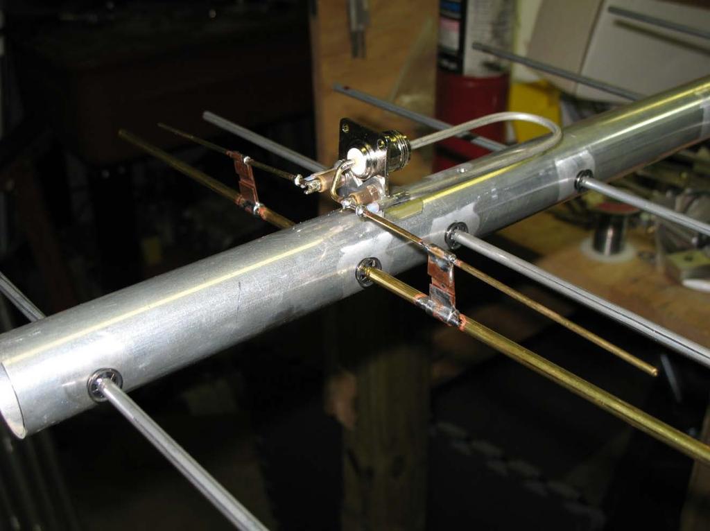
2 Page 2 CAUTION: While we strive to remove all burrs from all machined parts, there is always the possibility of sharp edges. We strongly suggest checking the edges and use a fine file, or 400 grit sandpaper, to remove any burrs that may have been left. Tools needed: #2 Phillips screwdriver ¼ flat blade screwdriver or 5/16 nut driver soldering gun or large iron rosin core solder large needle nosed pliers keeper installation tool (supplied with kit) ruler with metric millimeter markings marking pencil ASSEMBLY INSTRUCTIONS The antenna components should be removed carefully from the shipping container and the individual parts counted and checked for completeness. Be careful to check all tubing pieces for elements and hardware that may be packed inside. The boom consists of three pieces of tubing. The rear boom section has the driven element connector and balun already preassembled and attached; one end of the rear boom section is labeled #1 and mates with the center boom section also labeled #1. The other end of the center boom section is labeled #2 and mates with the front boom section also labeled #2. Slide the stainless steel hose clamp over the slotted portion of the center boom piece. Align the #8 hardware mounting holes and install an 8-32 X1 ¾ machine screw, lock washer and hex nut and tighten. Position the hose clamp ¼ from the end of the center boom section and tighten. The element bundle contains all of the elements needed for assembly. Take time to inventory each one and check off each dimension with Table 1. Some elements vary by 1 or 2mm in overall length, so extreme care in measuring is called for here. Arrange elements in order of descending size and mark each element with a scribe for proper location of the "keeper" (see Table 1 again and Figure 1). The reflector is the longest element, and each succeeding director is slightly shorter. DIR # 23 is the shortest. The keeper must be installed as shown in Figure 2; using the aluminum tubing tool supplied, slide the keeper to within a mm of the scribed line. Note that the keeper is a one way device only. If you go past the scribed line, you must continue to the element end and start the process over. Place the first keeper on all elements.
3 Page 3 FIGURE 1. FIGURE 2. You are now ready to install the elements on the boom. You must start at one end and work your way, in order, to the far end of the boom. Lay out the elements in ascending or descending order as appropriate. Insert insulators into element holes in each side of the boom at the starting end. Push element through insulator on one side about ½ to set locking tabs. Now insert the element from the other side through both insulators and install the second keeper on the opposite side of the boom from the first keeper. (See Figure 3) Check that the element is centered before you snug up both keepers. A positioning error of +/- 1mm. or 0.040" is acceptable. At this point, if you tighten the keepers and the element is not centered, you will have to cut one of the keepers to remove the element and start again. Some extra keepers are supplied, but care is definitely required here. Check your work as you go! Proceed with the next element in similar fashion. Note that the driven element is brass tube, but otherwise is installed the same as the other elements. Check off each element on Table 1 to monitor your progress. Double-check element lengths one last time before final installation on the boom. FIGURE 3. The driven element and T-Match assembly are built as shown in Figures 4 & 5 and the photographs below. Locate the two brass T-arms. Both are preformed- one is straight with a flattened end, while the other is bent and flattened on one end. Locate also the brass T-match bars, and position them on the brass driven element as shown in Figure 4.

4 Page 4 Photo 1 Photo 2

5 Page 5 Install the two T-match rods and T-match bars on the driven element as shown in the diagram (Figure 4). Note that the formed end of the bent T-match rod is inserted into the solder cup of the Type N connector and routed through the pre-assembled standoff insulator. Solder the brass tee arm to the connector center pin and the two standoffs. FIGURE 4. If you are installing multiple antennas, please be sure that you build each antenna with the same T-match wire orientation. In the above drawing, the center pin goes to the right hand side of the antenna as viewed from the back of the connector. Make sure both antennas do the same! Proper phase relationship is very important here! Align the T-match bars parallel with the edge of the connector bracket, and adjust their position as shown in Figures 4 and 5. You can slide the bars carefully into position. Be careful and do not apply excessive force to the standoff insulators. They are easily broken with rough handling. You may have to bend the connector bracket slightly to achieve the listed dimensions. FIGURE 5.
6 Page 6 Carefully form the pre-trimmed balun center leads around the T-Match rods as shown in Figure 4 and 5. Be careful to bend the stiff center conductor without deforming the rods. Use needle nose pliers. Solder the balun connection on each side. Trim the excess T-Match rods as shown in Figure mm is the proper dimension as measured from the midpoint of the connector to the extremity of the wire. The T-Match bars should be now set to the indicated position in Figure 4. If you wish to check your work, now is the time to apply power to the antenna. Any work around RF energy should be done carefully. We do not recommend standing next to an antenna with many watts of 432 MHz energy radiating around it. An MFJ 259 analyzer, Comet CAA-500 or VNA can also be used. The T-Match straps may be adjusted with power applied and the point of best match can be found quickly, easily and more accurately than that with an amateur transmitter and wattmeter connected. Generally, good watt meters can reliably indicate SWR down to about 1.2:1. The aperture of this antenna is large enough so that you must elevate the antenna a minimum of 7 feet or 2.1m above the ground. Point the antenna so that there are no "reflectors" or obstructions for 100 feet directly in front of the beam. A better method would be to point the antenna straight up toward the sky. Support the rear of the antenna on a wooden or metal pole or tube, and tie or guy the antenna boom with very light string or line. Now the driven element will be at arm level, and ground effects are removed. Most locations are pretty clear straight over head as well! Install a short length of coax (1/2 wave is ideal... the antenna impedance will repeat each half wave from the antenna regardless of coax imperfections) between the coax connector and your bridge or wattmeter. If you are using your transmitter for an RF source, apply power and observe the reflected power. Turn off the power and adjust the T-Match bars equally in small increments. 1/8" or 3mm is a good starting point. Apply power again and observe results. If it got better, keep going. If it degraded, change the direction of your T- Match movement program and recheck your SWR. At some point you will observe a null in reflected power. When you have found it, mark the point on the driven element, then solder the T-Match bars to the brass driven element and #12 wires. A large watt solder gun or iron is required here. Clean off excess flux. Brass, copper and tin lead solder will oxidize in the weather and over the years performance can degrade. It is a good idea to spray your handiwork with a good grade of clear paint sealant. As a general rule, the slower drying sprays tend to be more enduring. Rustoleum "Clear Seal" or Krylon clear sprays are recommended. A few light coats work better than one big one. Be sure to cover the connector before spraying. You are now ready to install your new antenna. Be careful when you dress the coax down the boom. Keep the coax away from any elements. Tape the cable tightly and securely to the boom. The Boom-to Mast plate has V shaped grooves to fit mast sizes up to 2" maximum. The small 1/4" U bolts are used to attach the boom to the mounting plate. Use the supplied lock washers. It is a good idea to apply a small amount of white lubricant grease to the stainless steel threads under the hex nuts to prevent galling of stainless steel. If you don't have it, don't worry about it.
7 Page 7 ELEMENT NUMBER ELEMENT TABLE ELEMENT LENGTH mm. KEEPER HALF LENGTH mm. REFLECTOR DRIVEN ELEMENT DIRECTOR # DIRECTOR # DIRECTOR # DIRECTOR # DIRECTOR # DIRECTOR # DIRECTOR # DIRECTOR # DIRECTOR # DIRECTOR # DIRECTOR # DIRECTOR # DIRECTOR # DIRECTOR # DIRECTOR # DIRECTOR # DIRECTOR # DIRECTOR # DIRECTOR # DIRECTOR # DIRECTOR # DIRECTOR # DIRECTOR # TABLE 1. All measurements are in Millimeters.
8 Page 8 Typical Return Loss plot using supplied dimensions. Just for reference, db Return Loss is approximately 1.05:1 VSWR!! Directive Systems Warranty Policy All Directive Systems antennas are built with the finest materials available. We take great pride in building a quality product that will give years of good service and performance. If there is a defect in materials or workmanship within 90 days of purchase, Directive Systems will repair or replace, free of charge, the defective part. DO NOT RETURN ANYTHING WITHOUT PRIOR AUTHORIZATION FROM DIRECTIVE SYSTEMS. Please contact us either by phone or describing the problem and we will work to resolve it. If, after examining a new antenna you received, you are not satisfied, contact us immediately for return authorization and refund. ANY ANTENNA THAT HAS BEEN MODIFIED WILL BE SUBJECT TO A RESTOCKING CHARGE. IF AN ANTENNA IS SO MODIFIED AS TO MAKE IT UNUSABLE, DIRECTIVE SYSTEMS RESERVES THE RIGHT TO REFUSE TO ACCEPT THE ANTENNA FOR RETURN.
Directive Systems & Engineering 2702 Rodgers Terrace Haymarket, VA
 Directive Systems & Engineering 2702 Rodgers Terrace Haymarket, VA 20169 1628 www.directivesystems.com 703 754 3876 K1JX DESIGNED 6 ELEMENT 50 MHZ YAGI, DSEJX6 50 INTRODUCTION The Directive Systems DSEJX6-50
K1FO 12 ELEMENT 144/147 MHz YAGI
 K1FO 12 ELEMENT 144/147 MHz YAGI WARNING: INSTALLATION OF THIS PRODUCT NEAR POWER LINES IS DANGEROUS. FOR YOUR SAFETY FOLLOW THE INSTALLATION DIRECTIONS. Ariane Arrays, Inc. Copyright 2006 201 Hopedale
INSTRUCTION MANUAL. Specifications Mechanical. 1 5/8 to 2 1/16 O.D. (41mm to 52mm)
") 308 Industrial Park Road Starkville, MS 39759 USA Ph: (662) 323-9538 FAX: (662) 323- General Description Model VB-25FM 2-Meter 5 Elements Beam INSTRUCTION MANUAL This antenna is a 5-element, 2-meter beam
308 Industrial Park Road Starkville, MS 39759 USA Ph: (662) 323-9538 FAX: (662) 323- General Description Model VB-25FM 2-Meter 5 Elements Beam INSTRUCTION MANUAL This antenna is a 5-element, 2-meter beam
Model VB-23FM 2-Meter 3-Element Beam
 308 Industrial Park Road Starkville, MS 39759 USA Ph: (662) 323-9538 FAX: (662) Model VB-23FM 2-Meter 3-Element Beam [ INSTRUCTION MANUAL Figure 1 Overall View and Boom Detail GENERAL DESCRIPTION This
M2 Antenna Systems, Inc. Model No: 2M4
 M2 Antenna Systems, Inc. Model No: 2M4 SPECIFICATIONS: Model... 2M4 Frequency Range... 144 To 148 MHz *Gain... 9.6 dbi Front to back... 20 db Typical Beamwidth... E=54 H=74 Feed type... T Match Feed Impedance....
M2 Antenna Systems, Inc. Model No: 2M7
 M2 Antenna Systems, Inc. Model No: 2M7 SPECIFICATIONS: Model... 2M7 Frequency Range... 144 To 148 MHz *Gain... 12.3 dbi Front to back... 20 db Typical Beamwidth... E=43 H=50 Feed type... T Match Feed Impedance....
THIS SHOULD TWEAK YOUR IMAGINATION
 10-27-05 THIS SHOULD TWEAK YOUR IMAGINATION SPECIFICATIONS FOR SINGLE ANTENNA MODEL NUMBER... 432EME-12 FREQUENCY... 430-436 MHz GAIN... 14.4 dbd FRONT TO BACK... 23 db VSWR... 1.2:1 TYPICAL BEAMWIDTH...
M2 Antenna Systems, Inc. Model No: YAGI ANTENNA
 M Antenna Systems, Inc. Model No: 4.5-7 YAGI ANTENNA SPECIFICATIONS: Model... 4.5-7 Frequency Range... 4.0 To 4.5 MHz *Gain... 0 To 7 dbi Front to back... 0 db over the rear 80 Beamwidth... E=44 H=50 typical
INSTRUCTION MANUAL. Specifications Electrical. Front-To-Back Ratio VSWR at Resonance Less than 1.5:1 Nominal Impedance. Mechanical
 300 Industrial Park Road, Starkville, MS 39759 Ph: (662) 323-8538 FAX: (662) 323-6551 TH-3JRS Tri-band HF 3 Elements Beam Covers 10, 15 and 20 Meters INSTRUCTION MANUAL WARNING Installation of this product
LJ element beam for 10 or 12 meters INSTRUCTION MANUAL. CAUTION: Read All Instructions Before Operating Equipment
 LJ-113 3 element beam for 10 or 1 meters INSTRUCTION MANUAL CAUTION: Read All Instructions Before Operating Equipment 308 Industrial Park Road Starkville, MS 39759 USA Tel: 66-33-9538 Fax: 66-33-6551 VERSION
M2 Antenna Systems, Inc. Model No: 2MCP22
 M2 Antenna Systems, Inc. Model No: 2MCP22 SPECIFICATIONS: Model... 2MCP22 Frequency Range... 144 To 148 MHz *Gain... 14.39 dbic Front to back... 25 db Typical Elipticity... >3db Beamwidth... 38 Feed type...
M2 Antenna Systems, Inc. Model No: 436CP30
 M2 Antenna Systems, Inc. Model No: 436CP30 SPECIFICATIONS: Model... 436CP30 Frequency Range... 432 To 440 MHz *Gain... 15.50 dbic Front to back... 18 db Typical Elipticity... 1.5 db Typical Beamwidth...
M2 Antenna Systems, Inc. Model No: 450CP26
 M2 Antenna Systems, Inc. Model No: 450CP26 SPECIFICATIONS: Model... 450CP26 Frequency Range... 445 To 455 mhz *Gain... 16.5 dbi Front to back... 21 db Typical Beamwidth... 30 Circular Feed type... T Match
M2 Antenna Systems, Inc. Model No: 450CP34
 M2 Antenna Systems, Inc. Model No: 450CP34 SPECIFICATIONS: Model... 450CP34 Frequency Range... 435 To 455 mhz *Gain... 16.0 dbi Front to back... 22 db Typical Beamwidth... 28 Circular Feed type... T Match
M2 Antenna Systems, Inc. Model No: 456CP34
 M2 Antenna Systems, Inc. Model No: 456CP34 SPECIFICATIONS: Model... 456CP34 Frequency Range... 435 To 470 mhz *Gain... 16.0 dbi Front to back... 23 db Typical Beamwidth... 30 Circular Feed type... T Match
Cushcraft. Amateur Radio Antennas LFA-6M5EL. 6 Meter 5 Element Loop Feed Antenna INSTRUCTION MANUAL
 Cushcraft Amateur Radio Antennas LFA-6M5EL 6 Meter 5 Element Loop Feed Antenna INSTRUCTION MANUAL CAUTION: Read All Instructions Before Operating Equipment VERSION 1A Cushcraft Amateur Radio Antennas 308
M2 Antenna Systems, Inc. Model No: 2M5WL
 M2 Antenna Systems, Inc. Model No: 2M5WL SPECIFICATIONS: Model... 2M5WL Frequency Range... 144 To 148 MHz *Gain... 16.84 dbi Front to back... 22 db Typical Beamwidth... E=26 H=29 Feed type... T Match Feed
Cushcraft. Amateur Radio Antennas DB-46M8EL. Dual band 6 and 4 Meter, 8 Element Beam Antenna INSTRUCTION MANUAL
 Cushcraft Amateur Radio Antennas DB-46M8EL Dual band 6 and 4 Meter, 8 Element Beam Antenna INSTRUCTION MANUAL CAUTION: Read All Instructions Before Operating Equipment VERSION 1B Cushcraft Amateur Radio
M2 Antenna Systems, Inc. Model No: 20M5LD
 M2 Antenna Systems, Inc. Model No: 20M5LD SPECIFICATIONS: Model... 20M5LD Frequency Range... 14.0 14.350 MHz *Gain (Full Band)... 10.2 dbi Typical Front to back... 23 db Typical Beamwidth... E=50 / H=66
INSTRUCTION MANUAL. Model 18AVQII Five Band Vertical Antenna 10, 15, 20, 40, 80 Meter. General Description. Theory of Operation
 Model 18AVQII Five Band Vertical Antenna 10, 15, 20, 40, 80 Meter 308 Industrial Park Road Starkville, MS 39759 (662) 323-9538 Fax: (662) 323-5803 INSTRUCTION MANUAL General Description The Hy-Gain 18AVQII
CP6A. 6 Band Trap Vertical 75-6m
 CP6A 6 Band Trap Vertical 75-6m Instruction Sheet The CP6A is a multi-band trap-vertical antenna for HF bands, covering the 75*, 40, 20, 15, 10m & 6m amateur bands. Made from heavy duty aluminum, the CP6A
M2 Antenna Systems, Inc. Model No: 20M6-125
 M2 Antenna Systems, Inc. Model No: 20M6-125 SPECIFICATIONS: Model... 20M6-125 Frequency Range... 14.0 14.350 MHz *Gain, (FS) / Over gnd... 11.19dBi / 16.6dBi @70 Front to back... 25 db Typical Beamwidth...
Model 6025 Single-Boom
 Log Periodic FM Broadcast Antenna Model 6025 Single-Boom Instruction Manual Installation, Operation, & Maintenance Congratulations! Thank you for purchasing one of the finest FM broadcast antennas on the
REP Design LLC. 193 Winding Ridge Rd, Southington, CT INSTALLATION INSTRUCTIONS:
 REP Design LLC 193 Winding Ridge Rd, Southington, CT 06489 1-860.426.1894 n7emw@cox.net www.repdesign.us INSTALLATION INSTRUCTIONS: SHD-SO239 Super Heavy Duty SO-239Antenna Mounting System Thank you for
INSTRUCTION MANUAL. Model VB-215DX MECHANICAL DESIGN GENERAL DESCRIPTION ELECTRICAL DESIGN. 2 Meter 15 Element Yagi for SSB/CW
 Model VB-215DX 2 Meter 15 Element Yagi for SSB/CW INSTRUCTION MANUAL GENERAL DESCRIPTION The Hy-Gain Model 215DX is a high performance yagi antenna for SSB/CW DXing in the Amateur 2 meter band. It features
Installation Instructions Hustler 6-BTV Trap Vertical
 Installation Instructions Hustler 6-BTV Trap Vertical ASSEMBLY 1. Check the package contents against the parts list on page 2. 2. WARNING. Installation of this product near power lines is dangerous. For
MI: (Secure this number someplace, for possible future need) SPECIFICATIONS:
 SPECIFICATIONS:") 6C ASSEMBLY INSTRUCTIONS ANTENNA MODEL T6 MI: 030927 (Secure this number someplace, for possible future need) SPECIFICATIONS: FORWARD GAIN 5.1 dbd F:B RATIO 15-25 db (Rises with frequency) FREQUENCY COVERAGE
6C ASSEMBLY INSTRUCTIONS ANTENNA MODEL T6 MI: 030927 (Secure this number someplace, for possible future need) SPECIFICATIONS: FORWARD GAIN 5.1 dbd F:B RATIO 15-25 db (Rises with frequency) FREQUENCY COVERAGE
Installation Instructions Hustler 6-BTV Trap Vertical
 Installation Instructions Hustler 6-BTV Trap Vertical ASSEMBLY 1. Check the package contents against the parts list on page 2. 2. WARNING. Installation of this product near power lines is dangerous. For
INSTRUCTION MANUAL for MODEL TH6-DX "THUNDERBIRD" (389)
") INSTRUCTION MANUAL for MODEL TH6-DX "THUNDERBIRD" (389) HY-GAIN ELECTRONICS CORPORATION, N. E. Hwy #6 at Stevens Creek, Lincoln, Nebraska 65801 Telephone 434-6331 INTRODUCTION Ely-Gain's new Model TH6-DX
INSTRUCTION MANUAL for MODEL TH6-DX "THUNDERBIRD" (389) HY-GAIN ELECTRONICS CORPORATION, N. E. Hwy #6 at Stevens Creek, Lincoln, Nebraska 65801 Telephone 434-6331 INTRODUCTION Ely-Gain's new Model TH6-DX
INSTRUCTION MANUAL V-42R. Dual Band Collinear Gain Vertical for MHz and GENERAL DESCRIPTION
 308 Industrial Park Road, Starkville, MS 39759 USA Ph: (662) 323-9538 FAX: (662) 323-6551 V-42R Dual Band Collinear Gain Vertical for 144-148 MHz and 436-450 INSTRUCTION MANUAL GENERAL DESCRIPTION The
JK-65 Five Element 6M Yagi
 JK-65 Five Element 6M Yagi PO Box 266, Croton Falls, NY 10519-0266 845.228.8700 (TEL) 845.279.5526 (FAX) info@jkantennas.com Page 1 of 8 JK Antennas Limited Warranty and Liability JK Antennas ( Manufacturer
PAC-12 Kit Contents. Tools Needed Soldering iron Phillips screwdriver Wire stripper Wrenches, 7/16 and 1/2 Terminal crimp tool Pliers Solder
 PAC-2 Kit Contents Part Quantity Screws: 8/32 x 3/8 Screws: 8-32 x 5/6 Screw: 8-32 x /4 #8 internal tooth washers #8 solder lug ring terminals Bolt: Aluminum, /4-20 x.5 /4 internal tooth washer Nut: Aluminum
MODEL DB-1015A 10- and 15-Meter Duo-Band Antenna Order No. 330
 MODEL DB-1015A 10- and 15-Meter Duo-Band Antenna Order No. 330 HY-GAIN ELECTRONICS CORPORATION 8601 Northeast Highway 6 Lincoln, Nebraska 68505 Telephone 464-9151 Area Code 402 TABLE OF CONTENTS page SECTION
Circularly Polarized FM Broadcast Antenna
 Circularly Polarized FM Broadcast Antenna Versa2une (SLV) 6 to 12-bay, full-wave-spaced Instruction Manual Installation, Operation, & Maintenance Congratulations! Thank you for purchasing one of the finest
Model CR 146/440. ArrowAntennas.com Simply the Best. Corner Reflector for 146 & 440 MHz. (307)
") 911 E. Fox Farm Rd. #2 Cheyenne, WY 82007 ArrowAntennas.com Simply the Best (307) 222-4712 info@arrowantennas.com Corner Reflector for 146 & 440 MHz Guarantee No hassle refund If you are not completely
911 E. Fox Farm Rd. #2 Cheyenne, WY 82007 ArrowAntennas.com Simply the Best (307) 222-4712 info@arrowantennas.com Corner Reflector for 146 & 440 MHz Guarantee No hassle refund If you are not completely
M2 Antenna Systems, Inc. Model No: KT31WARC
 M2 Antenna Systems, Inc. Model No: KT31WARC SPECIFICATIONS: Model... KT31WARC Frequency Range... 10.1-10.15 MHz **Selectable Frequency Range... 14.0-14.35 MHz **Selectable... (175 KHz / 2:1 VSWR Nominal)
DB Duo-Monoband Beam 7 - Element, 12 and 17 Meter INSTRUCTION MANUAL. General Description
 308 Industrial Park Road Starkville, MS 39759 USA Ph: (662) 323-9538 FAX: (662) 323-6551 DB- 1217 Duo-Monoband Beam 7 - Element, 12 and 17 Meter INSTRUCTION MANUAL General Description The Hy-Gain DB-1217
M2 Antenna Systems, Inc. Model No:
 M2 Antenna Systems, Inc. Model No: 400-600-10 SPECIFICATIONS: Model... 400-600-10 Frequency Range... 390 To 650 MHz *Gain... 12 To 13 dbic Front to back... 20 db Nominal Beamwidth... 46 Nominal Feed Impedance....
TELEX, liutiiilio"i TELEX COMMUNICATIONS, INC ALDRICH AVE. SO. MINNEAPOLIS. MN USA
 TELEX, liutiiilio"i TELEX COMMUNICATIONS, INC. 9600 ALDRICH AVE. SO. MINNEAPOLIS. MN 55420 USA INSTRUCTION MANUAL ORDER NO. 410 General This antenna is a five-element, Citizens Band beam with a forward
JK M Hi-Q Coil Loaded Rotatable Dipole Version
 JK-401 40M Hi-Q Coil Loaded Rotatable Dipole 2018 Version 72 Grays Bridge Road, Unit D, Brookfield, CT 06804 845.228.8700 (TEL) 845.279.5526 (FAX) info@jkantennas.com LAST UPDATED: 02-01-2018 JK Antennas
PACKING LIST MACO V-5000
 PACKING LIST MACO V-5000 PART QTY O.D. SIZE LENGTH DESCRIPTION CHECKLIST T47P 4 5/8.050 36 Aluminum Tubing _ T43P 1 7/8.050 48 Aluminum Tubing _ T18P 1 3/4.050 48 Aluminum Tubing _ T15P 1 5/8.050 48 Aluminum
M2 Antenna Systems, Inc. Model No: 435XP50
 M2 Antenna Systems, Inc. Model No: 435XP50 SPECIFICATIONS: Model... 435XP50 Frequency Range... 430 To 436 MHz *Gain... 19.2 dbi Front to back... 22 db Typical Cross pol. isolation... >20 db Typical Beamwidth...
A Folding 5-Element Yagi for 144 MHz
 A Folding 5-Element Yagi for 144 MHz Steve Kavanagh, VE3SMA, April 2017 1. Introduction I have found antennas which fold up quickly to take less space in the car to be useful in VHF/UHF portable operating.
CP6 6 Band Trap Vertical 80-6m
 CP6 6 Band Trap Vertical 80-6m Instruction Sheet The CP6 is a multi-band trap-vertical antenna for HF bands, covering the 80*, 40, 20, 15, 10m & 6m amateur bands. Made from heavy duty aluminum, the CP6
M2 Antenna Systems, Inc. Model No: 40M3L
 M2 Antenna Systems, Inc. Model No: 40M3L SPECIFICATIONS: Model... 40M3L Frequency Range... 7.0-7.3 MHz X 150 khz Gain... 6.6 dbi Front to back... 23 db Beamwidth... E=62 Feed type... Hair pin match Feed
ASSEMBLY AND INSTALLATION INSTRUCTIONS R , 12, 15, 17, 20, 30, 40 Meters (5/99) COMMUNICATIONS ANTENNAS
 COMMUNICATIONS ANTENNAS") ASSEMBLY AND INSTALLATION INSTRUCTIONS R7000 10, 12, 15, 17, 20, 30, 40 Meters COMMUNICATIONS ANTENNAS 951465 (5/99) WARNING THIS ANTENNA IS AN ELECTRICAL CONDUCTOR. CONTACT WITH POWER LINES CAN RESULT
ASSEMBLY AND INSTALLATION INSTRUCTIONS R7000 10, 12, 15, 17, 20, 30, 40 Meters COMMUNICATIONS ANTENNAS 951465 (5/99) WARNING THIS ANTENNA IS AN ELECTRICAL CONDUCTOR. CONTACT WITH POWER LINES CAN RESULT
INSTRUCTION MANUAL. Model 18AVQII Five Band Vertical Antenna 10, 15, 20, 40, 80 Meter
 Model 18AVQII Five Band Vertical Antenna 10, 15, 20, 40, 80 Meter 308 Industrial Park Road Starkville, MS 39759 (662) 323-9538 Fax: (662) 323-5803 INSTRUCTION MANUAL General Description The Hy-Gain 18AVQII
C O R P O R A T I O N
 ASSEMBLY AND INSTALLATION INSTRUCTIONS A4S 20 / 5 / 0 MeterBeam C O R P O R A T I O N 95279 (8/98) WARNING THIS ANNNA IS AN ELECTRICAL CONDUCTOR. CONTACT WITH POWER LINES CAN RESULT IN DEATH, OR SERIOUS
MFJ-1835K34 40,30 METER ADD ON KIT FOR THE MFJ-1835 COBWEB ANTENNA INSTRUCTION MANUAL. CAUTION: Read All Instructions Before Operating Equipment
 MFJ-1835K34 40,30 METER ADD ON KIT FOR THE MFJ-1835 COBWEB ANTENNA INSTRUCTION MANUAL CAUTION: Read All Instructions Before Operating Equipment 300 Industrial Park Road Starkville, MS 39759 USA Tel: 662-323-5869
MQ-24SR Miniature Four band Hybrid Quad Antenna
 MQ-24SR Miniature Four band Hybrid Quad Antenna Most antennas are large heavy structures requiring heavy duty structures, rotors and lots of extra muscle during installation and lots of extra dollars before
M2 Antenna Systems, Inc. Model No: 10-30LP8
 M2 Antenna Systems, Inc. Model No: 10-30LP8 SPECIFICATIONS: Model... 10-30LP8 Frequency Range... 10-30 MHz Continuous *Gain free space / 65... 5.2 dbi / 10.5 dbi 10-30 Front to back... 15 db 10-30 MHz
Model CR146. ArrowAntennas.com Simply the Best. Corner Reflector for 146 MHz. (307)
") 911 E. Fox Farm Rd. #2 Cheyenne, WY 82007 ArrowAntennas.com Simply the Best (307) 222-4712 info@arrowantennas.com Corner Reflector for 146 MHz Guarantee No hassle refund If you are not completely satisfied
911 E. Fox Farm Rd. #2 Cheyenne, WY 82007 ArrowAntennas.com Simply the Best (307) 222-4712 info@arrowantennas.com Corner Reflector for 146 MHz Guarantee No hassle refund If you are not completely satisfied
TZ-RD-1740 Rotary Dipole Instruction Manual
 TZ-RD-1740 17/40m Rotary Dipole Instruction Manual The TZ-RD-1740 is a loaded dipole antenna for the 40m band and a full size rotary dipole for the 17m band. The antenna uses an aluminium radiating section
INSTRUCTION MANUAL VB-66DX. 6-Meter 6-Element Beam. Preparation For Assembly. General Description
 VB-66DX 308 Industrial Park Road Starkville, MS 39759 USA Ph: (662) 323-9538 FAX: (662) 323-6551 6-Meter 6-Element Beam INSTRUCTION MANUAL General Description The Hy-Gain Model 66DX is a full sized 6-
TENNADYNE. Aluminum with a PhD. Tennadyne ASSEMBLY INSTRUCTIONS MODEL: T Log Periodic Antennas SPECIFICATIONS:
 TENNADYNE Aluminum with a PhD ASSEMBLY INSTRUCTIONS MODEL: T10-100224 SPECIFICATIONS: FREQUENCY COVERAGE 13-33 MHz FORWARD GAIN 6.1 dbd ½ POWER BEAMWIDTH 52 DEGREES F:B RATIO To 25 Db (Rises with frequency)
Assembly Instructions for the 10N6RDB Antenna
 Assembly Instructions for the 10N6RDB Antenna The 10N6RDB antenna comes from the factory almost completely assembled. All you have to do is install the 1/2 inch Aluminum tubing at both ends of the 10 Meter
Cisco Aironet 13.5-dBi Yagi Mast Mount Antenna (AIR-ANT1949)
") Cisco Aironet 13.5-dBi Yagi Mast Mount Antenna (AIR-ANT1949) Overview This document describes the 13.5-dBi Yagi mast mount antenna and provides instructions for mounting it. The antenna operates in the
Cisco Aironet 13.5-dBi Yagi Mast Mount Antenna (AIR-ANT1949) Overview This document describes the 13.5-dBi Yagi mast mount antenna and provides instructions for mounting it. The antenna operates in the
Giraud Tool Company, Inc.
 Motor Upgrade for Gracey Trimmer This package is intended to allow the user to upgrade their Gracey trimmer with a higher rpm motor and convenience features not found in the production offering. This upgrade
INSTALLATION INSTRUCTIONS CONTOURED LIGHT BAR APPLICATION: CHEVY EQUINOX/ GMC TERRAIN PART NUMBERS: ,
 INSTALLATION INSTRUCTIONS CONTOURED LIGHT BAR APPLICATION: 2010-2014 CHEVY EQUINOX/ GMC TERRAIN PART NUMBERS: 32-21020, 32-21025 ITEM QUANTITY DESCRIPTION TOOLS NEEDED 1 1 CONTOUR BAR TORQUE WRENCH 2 1
Pacific Antenna 20 and 40M Lightweight Dipole Kit
 Pacific Antenna 20 and 40M Lightweight Dipole Kit Diagram showing configuration and approximate lengths 8 3 16 9 16 9 8 3 Description The Pacific Antenna lightweight dual band, trap dipole kit provides
JK-404 GRANDE Four Element Full Size 40M Yagi
 JK-404 GRANDE Four Element Full Size 40M Yagi PO Box 266, Croton Falls, NY 10519-0266 845.228.8700 (TEL) 845.279.5526 (FAX) info@jkantennas.com JK Antennas Limited Warranty and Liability JK Antennas (
9 Element Yagi for 2304 MHz
 9 Element Yagi for 2304 MHz Steve Kavanagh, VE3SMA Design Dipole-based Yagi designs for 2304 MHz are rare, partly because they are a bit tricky to build and partly because the loop yagi has completely
Spiderbeam Balun Construction Guide
 BALUN CONSTRUCTION GUIDE Ver. 1.0 1 The components of the Balun Kit are in a plastic bag. Most of the components are inside the plastic case of the balun. The aluminum U-profile and the RG-142 Teflon Coax
M2 Antenna Systems, Inc. Model No: 10-30LP8
 M2 Antenna Systems, Inc. Model No: 10-30LP8 VSWR 2:1 TYPICAL VSWR @ 70 FT. 2:1 1.5:1 1.5:1 1.2:1 1.2:1 10 14 MHz 11 12 13 17 15 16 18 19 20 21 22 23 24 25 26 27 28 29 30 SPECIFICATIONS: Model...10-30LP8
Pacific Antenna 20 and 40M Lightweight Dipole Kit
 Pacific Antenna 20 and 40M Lightweight Dipole Kit Antenna diagram showing configuration and lengths when assembled 7 8 16 9 16 9 Description The Pacific Antenna lightweight dual band dipole kit provides
MFJ ENTERPRISES, INC.
 Model MFJ-2910 INSTRUCTION MANUAL CAUTION: Read All Instructions Before Operating Equipment MFJ ENTERPRISES, INC. 300 Industrial Park Road Starkville, MS 39759 USA Tel: 662-323-5869 Fax: 662-323-6551 VERSION
MFJ-1762 Instruction Manual
 MFJ-1762 Instruction Manual INTRODUCTION Thank you for purchasing the MFJ-1762 three-element six-meter Yagi. The MFJ-1762 is a light-weight directional antenna especially designed for installation with
Cisco Aironet 2.4-GHz/5-GHz 8-dBi Directional Antenna (AIR-ANT2588P3M-N)
") Cisco Aironet.4-GHz/5-GHz 8-dBi Directional Antenna (AIR-ANT588P3M-N) This document outlines the specifications for the Cisco Aironet AIR-ANT588P3M-N.4/5-GHz 8-dBi 3-Port Directional Antenna with N-connectors
Cisco Aironet.4-GHz/5-GHz 8-dBi Directional Antenna (AIR-ANT588P3M-N) This document outlines the specifications for the Cisco Aironet AIR-ANT588P3M-N.4/5-GHz 8-dBi 3-Port Directional Antenna with N-connectors
Hardware and Components:
 Hardware and Components: (A) 5/16 x 2 Hex Bolt (B) 5/16 x 2-1/4 Hex Bolt (C) 5/16 x 2-1/2 Hex Bolt (D) 4X 5/16 x 3/4 Hex Bolt (E) 4X 5/16 x 1-1/4 Hex Bolt (F) 11X 5/16 Flat Washer (G) 12X 5/16 Nylock Nut
M2 Antenna Systems, Inc. Model No: 2M HO LOOP
 M2 Antenna Systems, Inc. Model No: 2M HO LOOP SPECIFICATIONS: Model... 2M HO LOOP Frequency Range... 144 To 144.5 MHz Gain, Typical @ 10 ft.... 4 dbd @ 10 deg. Gain, 2 STK @ 82 & 132... 8 dbd @ 9 deg.
MOUNTING INSTRUCTIONS
 Standard Mounting Bracket Tilting Bracket* Mounting example Right side for upper tilt from 0 to 20 20 Spare parts: p/n SA197 Materials: extruded aluminum Hardware: stainless & zinc plated steel Dimensions
MFJ Instruction Manual Table of Contents
 Table of Contents MFJ-1768 Introduction...2 Choosing a Location for the Antenna...2 Tools and Time Requirements...3 MFJ-1768 Parts List...3 Safety Precautions...3 Assembly and Installation...4 Tuning...7
Assembly Instructions: Bencher Skylark
 Assembly Instructions: Bencher Skylark Tools Required: Pop Rivet Tool Tape Measure Hex Wrenches Screwdriver Several Disposable Rags Two Saw Horses Several boxes or bowls to hold fasteners and small parts
MA5B 20 / 17 / 15 / 12 / 10 Meter Beam Antenna
 ASSEMBLY AND INSTALLATION INSTRUCTIONS NE 20 / 17 / 15 / 12 / 10 Meter Beam Antenna 951485_GF_AB WARNING THIS ANTENNA IS AN ELECTRICAL CONDUCTOR. CONTACT WITH POWER LINES CAN RESULT IN DEATH, OR SERIOUS
WARNING EXTREME CARE MUST BE USED FOR YOUR SAFETY
 WARNING EXTREME CARE MUST BE USED FOR YOUR SAFETY PLANNING Plan your installation carefully. If you use volunteer helpers be sure that they are qualified to assist you. Make certain that everyone involved
Portable or Emergency VHF Antennas Paul R. Jorgenson KE7HR
 For emergency or public service events it is often necessary to have more antenna than the rubber duck on your handheld VHF radio. Nearly ANY external antenna will provide more coverage for your handheld
HP ProCurve 6.9/7.7dBi Dual Band Directional Antenna (J8999A) Guide
 Guide") HP ProCurve 6.9/7.7dBi Dual Band Directional Antenna (J8999A) Guide SAFETY The HP ProCurve J8999A and all associated equipment should be installed in accordance with applicable local and national electrical
HP ProCurve 6.9/7.7dBi Dual Band Directional Antenna (J8999A) Guide SAFETY The HP ProCurve J8999A and all associated equipment should be installed in accordance with applicable local and national electrical
INSTRUCTION MANUAL ORDER NO. V3R MODEL V3R. Collinear Gain Vertical for MHz
 ORDER NO. V3R MODEL V3R Collinear Gain Vertical for 216-225 MHz INSTRUCTION MANUAL General Description The new Hy-Gain V3R VHF antenna is a collinear 5/8-wave omnidirectional vertical antenna for the 216-225
TELEX. iiilhiijiri INSTRUCTION MANUAL ORDER NO. 411 TELEX COMMUNICATIONS, INC ALDRICH AVE SO. MINNEAPOLIS. MN U.SA.
 TELEX. iiilhiijiri TELEX COMMUNICATIONS, INC. 9600 ALDRICH AVE SO. MINNEAPOLIS. MN 55420 U.SA. INSTRUCTION MANUAL ORDER NO. 411 Base Station, 5-Element Beam Antenna This antenna is a five element, Citizens
MFJ-2100 INSTRUCTION MANUAL. CAUTION: Read All Instructions Before Operating Equipment
 MFJ-2100 INSTRUCTION MANUAL CAUTION: Read All Instructions Before Operating Equipment 300 Industrial Park Road Starkville, MS 39759 USA Tel: 662-323-5869 Fax: 662-323-6551 COPYRIGHT C 2015 MFJ Enterprises
MHz. ANT150D, D3, D6-9 DIPOLE AND DIPOLE ARRAY 1 TO 9 dbd
 138-174 MHz ANTD, D3, D6-9 DIPOLE AND DIPOLE ARRAY 1 TO 9 dbd The Telewave ANTD series consists of single, dual, and 4-element di pole array antennas with a precision phasing harness for optimum per formance.
MFJ-2982 Feather-Lite 80-6 Meter Vertical Antenna
 MFJ-2982 Feather-Lite 80-6 Meter Vertical Introduction: The MFJ-2982 is a lightweight 31-foot fiberglass antenna designed to mount on any convenient post, mast, or a suitable wide-stance tripod such as
LIGHT BEAM ANTENNA MaxRange Antenna Series Assembly Instructions MaxRange Plus Digital / High Definition Television Antennas
 LIGHT BEAM ANTENNA MaxRange Antenna Series Assembly Instructions MaxRange Plus Digital / High Definition Television Antennas Assembly Instructions 1 MaxRange Plus Antenna These instructions will lead you
M2 Antenna Systems, Inc. Model No: 7&10-30LP8
 M2 Antenna Systems, Inc. Model No: 7&10-30LP8 2:1 100KHz BANDWIDTH@ 1.8:1 VSWR 1.5:1 6.9 7.0 7.1 10 FREQUENCY (MHZ) 20 SPECIFICATIONS: Model...7&10-30LP8 Skip log Frequency Range...10-30 MHz Continuous
Nancy s Knit Knacks LLC 4 Yard Option Upgrade Kit Assembly Instructions and User Manual
 Nancy s Knit Knacks LLC 4 Yard Option Upgrade Kit Assembly Instructions and User Manual Thank you for purchasing our 4 Yard Option (4YO) Upgrade Kit. To install this upgrade you are simply going to assemble
Standard Pole Mount Parabolic Antenna Mounting Instructions 3 ft. (90cm) & 4 ft. (120cm)
 & 4 ft. (120cm)") 495 R Billerica Ave. N. Billerica, MA 01862 USA Tel: (978) 459-8800 Fax: (978) 459-3310 / 8814 www.radiowavesinc.com email: sales@radiowavesinc.com Standard Pole Mount Parabolic Antenna Mounting Instructions
495 R Billerica Ave. N. Billerica, MA 01862 USA Tel: (978) 459-8800 Fax: (978) 459-3310 / 8814 www.radiowavesinc.com email: sales@radiowavesinc.com Standard Pole Mount Parabolic Antenna Mounting Instructions
M2 Antenna Systems, Inc. Model No: 10-30LP8-125
 M2 Antenna Systems, Inc. Model No: 10-30LP8-125 VSWR 2:1 TYPICAL VSWR @ 70 FT. 2:1 1.5:1 1.5:1 1.2:1 1.2:1 10 14 MHz 11 12 13 17 15 16 18 19 20 21 22 23 24 25 26 27 28 29 30 SPECIFICATIONS: Model...10-30LP8-125
1. Turn off or disconnect power to unit (machine). 2. Push IN the release bar on the quick change base plate. Locking latch will pivot downward.
. 2. Push IN the release bar on the quick change base plate. Locking latch will pivot downward.") Figure 1 Miniature Quick Change Applicators, of the end feed type, are designed to crimp end feed strip terminals to prestripped wires. Each applicator is set up to accept the strip form of certain specific
Figure 1 Miniature Quick Change Applicators, of the end feed type, are designed to crimp end feed strip terminals to prestripped wires. Each applicator is set up to accept the strip form of certain specific
PREPARATION FOR ASSEMBLY
 GENERAL DESCRIPTION The Hy-Gain Model 216 SAT is a high-performance "OSCAR" (Orbiting Satellite Carrying Amateur Radio) satellite antenna for the 145.8-146.0 MHz frequency hand. It features polarization
JK NAVASSA-5. 5-Band Yagi (20M/17M/15M/12M/10M) Optional 6M Add-on Kit Available
 Optional 6M Add-on Kit Available") JK NAVASSA-5 5-Band Yagi (20M/17M/15M/12M/10M) Optional 6M Add-on Kit Available 72 Grays Bridge Road, Unit D, Brookfield, CT 06804 845.228.8700 (TEL) 845.279.5526 (FAX) info@jkantennas.com Last Updated:
JK NAVASSA-5 5-Band Yagi (20M/17M/15M/12M/10M) Optional 6M Add-on Kit Available 72 Grays Bridge Road, Unit D, Brookfield, CT 06804 845.228.8700 (TEL) 845.279.5526 (FAX) info@jkantennas.com Last Updated:
TELEX COMMUNICATIONS, INC ALDRICH LIVE SO. MINNEAPOLIS. MN U S A. /~g-~~~~r iu IORDER NO. 337s
 IkEfEX N TELEX COMMUNICATIONS, INC. 300 ALDRICH LIVE SO. MINNEAPOLIS. MN 55420 U S A /~g-~~~~r iu IORDER NO. 337s MAN A I MODEL V4S Collinear Gain Vertical for 420450 MHz PN801910 General Description The
Model S9v. 43 Multiband Vertical Antenna Installation Guide
 Model S9v 43 Multiband Vertical Antenna Installation Guide. WARNING: INSTALLATION OF THIS PRODUCT NEAR POWERLINES IS DANGEROUS. FOR YOUR SAFETY, FOLLOW THE INSTALLATION DIRECTIONS. INTRODUCTION Thank you
Pacific Antenna 20 and 40M Lightweight Dipole Kit
 Pacific Antenna 20 and 40M Lightweight Dipole Kit Diagram showing configuration and approximate lengths 8 6 16 9 16 9 8 6 Description The Pacific Antenna lightweight dual band, trap dipole kit provides
1.8 METER SERIES 1184 ANTENNA SYSTEM
 REVISION F January 10, 2002 ASSEMBLY MANUAL 1.8 METER SERIES 1184 ANTENNA SYSTEM PRODELIN CORPORATION 1500 Prodelin Drive Newton NC 28658 1.8 METER SERIES 1184 ANTENNA SYSTEM F Revised Address 1/10/02
THE W3FF HOMEBREW BUDDIPOLE
 THE W3FF HOMEBREW BUDDIPOLE A PORTABLE ANTENNA DESIGN FOR AMATEUR RADIO History of the Buddipole In January of 2000, I began experimenting with a walking portable ham station. Since then, thousands of
M2 Antenna Systems, Inc. Model No: 40M2L
 M2 Antenna Systems, Inc. Model No: 40M2L SPECIFICATIONS: Model...40M2L Frequency Range...6.9-10 MHz X 150 khz Gain...5.5 dbi Front to back...13 15 db Beamwidth...E=74 Feed type...hair pin match Feed Impedance....50
Retractable Screen Installation Instructions For Vinyl and Aluminum Clad and Wood In-Swing Hinged Doors (See separate instructions for sliding doors)
") Retractable Screen Installation Instructions For Vinyl and Aluminum Clad and Wood In-Swing Hinged Doors (See separate instructions for sliding doors) IMPORTANT: Please read before you begin. Table of Contents
Retractable Screen Installation Instructions For Vinyl and Aluminum Clad and Wood In-Swing Hinged Doors (See separate instructions for sliding doors) IMPORTANT: Please read before you begin. Table of Contents
RBP-1215B-RX DODGE RAM QUAD CAB RX3
 RBP-1215B-RX3 2002-2017 DODGE RAM 15-3500 QUAD CAB RX3 Passenger side RX-3 Side Step Drill Template Passenger side rear Modular Bracket (6) L Support Brackets Driver side rear Modular Bracket Driver side
M2 Antenna Systems, Inc. Model No: KT34XA TO KT36XA UPGRADE KIT
 M2 Antenna Systems, Inc. Model No: KT34XA TO KT36XA UPGRADE KIT SPECIFICATIONS: SPECIFICATIONS for the KT34-6XA MODEL NUMBER...KT36XA FREQ. RANGE...14.0-14.35 MHz 21.0-21.45 MHz 28.0-29.0 MHz GAIN (Free
6M HALO VERSON II + OPTIONAL 2M GROUND PLANE
 The halo is an omnidirectional, horizontally polarized antenna with about the same gain as a dipole but without the low elevation nulls off the ends (+5.5 to +3.5dBi variation for the Halo vs. +7.9 to