9 Element Yagi for 2304 MHz
|
|
|
- Melvyn Russell
- 6 years ago
- Views:
Transcription
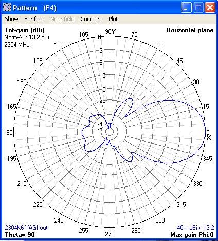
1 9 Element Yagi for 2304 MHz Steve Kavanagh, VE3SMA Design Dipole-based Yagi designs for 2304 MHz are rare, partly because they are a bit tricky to build and partly because the loop yagi has completely dominated this band in North America. There are a few 2320 MHz Yagi designs around from Europe. Wimo makes them commercially for the amateur market. An additional factor in popularity is the possible advantage loop yagis have in resistance to detuning from rain. I wanted to design a small antenna for contest rover operation, for working local stations without having to put up a big antenna which would overwhelm my small car. I optimized a design using the NEC2 based simulation software 4NEC2 by Arne Voors, which can be downloaded free from the internet. This incorporates some features which are unusual in Yagi designs for the lower microwave bands - The driven element is a centre-fed dipole (most designs use folded dipoles or loops). - It has a wood boom. - There is no explicit balun; the combination of the feed coax and the reflector element form a rudimentary balun to minimize current on the feedline behind the reflector. The 4NEC2 model shows very low SWR (less than 1.1) from MHz and a fairly flat gain with a peak of about 13.2 dbi a little above 2304 MHz (assuming perfectly conducting elements). When modelled using YA (from Brian Beezley, K6STI) the SWR is not as low but is around 1.3 or less from MHz. I decided this was good enough and proceeded to build the antenna. The following plots show the predicted performance (SWR, gain and patterns for horizontal polarization) from 4NEC2.
2

")
3 Construction The following photo shows the assembled (but not quite finished) antenna.
4 The boom is made from 1/8 inch plywood (cut to 1 x 12 inches) which I found at a craft supply store (Michael s). 1/16 diameter holes are drilled to take the elements (which have to be opened out a bit to take the parasitic elements, by pushing the drill bit against the sides of the holes). Three additional holes were drilled in the boom to reduce the loading effect of the wood on the feedline (forming part of the balun) between the driven element and the reflector. The boom is bolted at one end to a piece of thicker plywood which provides a location for the mast clamp and to mount the connector. The parasitic elements are made from #14 AWG (1.63 mm diameter) bare copper wire, with the ends filed flat to adjust the lengths within about 0.03 mm of the dimensions given below, using a dial or digital caliper the check the length. The wire tends to bend while filing so it is useful to have a couple of steel plates handy for rolling the wire straight again when this happens. The reflector is filed about halfway though at the centre using a small round file about the same diameter as the semi-rigid coax feedline. The element positions and lengths are given in the following table. These are the values used in the 4NEC2 model but with a length correction to account for the elements being solid rather than thin-wall tubing, which necessitates a reduction in length to take into account the capacitance of the ends of the elements. Probably there should be a boom correction for the reflector, but I did not take this additional step. Element Position (mm) Length (mm) Reflector (offset 1.8 mm upwards) Driven Element Director Director Director Director Director Director Director The driven element, reflector and feedline are assembled as a unit as follows. First the semi-rigid (RG-402/U or UT-141) feed coax is prepared. The piece I used had an SMA plug on one end, requiring the use of an adapter to get a rugged N-type interface. At the other end cut the shield off about 10 mm from the end (dimension is not critical). This can be done by deeply scoring around the shield with a knife and then breaking off the shield, or with a small saw. Also cut the insulation flush with the cut end of the shield. Now, file the shield off over one half of the circumference of the cable, for a length of about 2.5 mm. With a sharp knife slice off a piece of the insulation so the inner conductor can be bent over as shown in the following sketch.

5 The driven element is made up of two pieces of brass tubing (1/16 O.D., wall, made by K&L and available in good hobby shops) as shown in the sketch. One piece is slipped over the bent inner conductor and soldered in place while the other is soldered to the coax shield on the opposite side. I ended up needing to tune the driven element a bit to get the best match. The final version has pieces of #21 AWG (0.7 mm diameter) wire soldered into the outer ends of the tubing, protruding about 0.5 mm on each side. This is an odd wire size I used some clipped off component leads. #20 wire should fit and give about the same results. The reflector is soldered to the feedline (with the filed out indentation against the coax) 32.5 mm from the driven element (measured between the centres of the two elements). The following photo shows a close-up of the feed assembly. The feed assembly is positioned with the driven element half connected to the inner conductor pushed through the hole in the boom. This way the hole does not have to accommodate the large blob of solder on the other side of the coax. You will probably have to open out the reflector hole in the boom as the chances of getting the spacing of the holes and the spacing between the driven element and reflector exactly the same is pretty low. Once all the elements are inserted in their respective holes in the boom they are held in place with glue (I used 5 minute epoxy). I did not epoxy the coax side of the driven element. The directors are all offset a bit (compared to being centred on the boom) so that they are centred with respect to the feed coax. Some additional epoxy was used to hold the coax to the rear of the boom, enabling the coax to contribute significantly to the boom stiffness. The wood parts were given a couple of coats of varnish. Finally, the feedpoint and the holes in the boom were weatherproofed (hopefully!) by epoxying a piece cut from a blister pack over the driven element and reflector (with holes punched with a sharp point for those elements to pass through), and another small piece of flat plastic over the holes in the boom on the opposite side. The following photo shows the blister pack piece.

 indicate that the Yagi had about 5 db gain over a tomato puree can horn, which seems about right.")
6 Results I measured an SWR of about 1.3 at 2304 MHz (18 db return loss). Adding the small wire inserts at the ends of the driven element brought the SWR down just slightly. This SWR is as predicted by YA, but not as good as predicted by 4NEC2. Some very crude indoor range tests at MHz (in my living room!) indicate that the Yagi had about 5 db gain over a tomato puree can horn, which seems about right. The horizontal plane -3 db beamwidth was measured at 37 degrees, compared to 39 degrees from 4NEC2 and the beamwidth between the first pattern nulls was measured at 82 degrees, compared to 87 degrees from 4NEC2.
A Folding 11-Element Yagi for 432 MHz
 A Folding 11-Element Yagi for 432 MHz Steve Kavanagh, VE3SMA, October 2015 1. Introduction For portable VHF/UHF operation I have found it convenient at times to have some antennas which fold up quickly
A Folding 5-Element Yagi for 144 MHz
 A Folding 5-Element Yagi for 144 MHz Steve Kavanagh, VE3SMA, April 2017 1. Introduction I have found antennas which fold up quickly to take less space in the car to be useful in VHF/UHF portable operating.
Chapter 6 Antenna Basics. Dipoles, Ground-planes, and Wires Directional Antennas Feed Lines
 Chapter 6 Antenna Basics Dipoles, Ground-planes, and Wires Directional Antennas Feed Lines Some General Rules Bigger is better. (Most of the time) Higher is better. (Most of the time) Lower SWR is better.
6M HALO VERSON II + OPTIONAL 2M GROUND PLANE
 The halo is an omnidirectional, horizontally polarized antenna with about the same gain as a dipole but without the low elevation nulls off the ends (+5.5 to +3.5dBi variation for the Halo vs. +7.9 to
K1FO 12 ELEMENT 144/147 MHz YAGI
 K1FO 12 ELEMENT 144/147 MHz YAGI WARNING: INSTALLATION OF THIS PRODUCT NEAR POWER LINES IS DANGEROUS. FOR YOUR SAFETY FOLLOW THE INSTALLATION DIRECTIONS. Ariane Arrays, Inc. Copyright 2006 201 Hopedale
A short, off-center fed dipole for 40 m and 20 m by Daniel Marks, KW4TI
 A short, off-center fed dipole for 40 m and 20 m by Daniel Marks, KW4TI Version 2017-Nov-7 Abstract: This antenna is a 20 to 25 foot long (6.0 m to 7.6 m) off-center fed dipole antenna for the 20 m and
MFJ-219/219N 440 MHz UHF SWR Analyzer TABLE OF CONTENTS
 MFJ-219/219N 440 MHz UHF SWR Analyzer TABLE OF CONTENTS Introduction...2 Powering The MFJ-219/219N...3 Battery Installation...3 Operation Of The MFJ-219/219N...4 SWR and the MFJ-219/219N...4 Measuring
Construction manual for 50 MHz XL design yagi-kits
 Construction manual for 50 MHz XL design yagi-kits Source: http://www.nuxcom.de/pdf/nuxcom_construction-manual_6m-xl.pdf Please check if all parts listed in the invoice are delivered with the kit. In the
Cushcraft. Amateur Radio Antennas LFA-6M5EL. 6 Meter 5 Element Loop Feed Antenna INSTRUCTION MANUAL
 Cushcraft Amateur Radio Antennas LFA-6M5EL 6 Meter 5 Element Loop Feed Antenna INSTRUCTION MANUAL CAUTION: Read All Instructions Before Operating Equipment VERSION 1A Cushcraft Amateur Radio Antennas 308
Constructing VHF/UHF Antennas WB5CXC Larry Brown W5WF Charles Webb
 Constructing VHF/UHF Antennas WB5CXC Larry Brown W5WF Charles Webb We will be discussing construction of VHF/UHF antenna for portable and home use using common available materials. Our favorite supplies
INSTRUCTION MANUAL. Specifications Mechanical. 1 5/8 to 2 1/16 O.D. (41mm to 52mm)
") 308 Industrial Park Road Starkville, MS 39759 USA Ph: (662) 323-9538 FAX: (662) 323- General Description Model VB-25FM 2-Meter 5 Elements Beam INSTRUCTION MANUAL This antenna is a 5-element, 2-meter beam
308 Industrial Park Road Starkville, MS 39759 USA Ph: (662) 323-9538 FAX: (662) 323- General Description Model VB-25FM 2-Meter 5 Elements Beam INSTRUCTION MANUAL This antenna is a 5-element, 2-meter beam
INSTRUCTION MANUAL for MODEL TH6-DX "THUNDERBIRD" (389)
") INSTRUCTION MANUAL for MODEL TH6-DX "THUNDERBIRD" (389) HY-GAIN ELECTRONICS CORPORATION, N. E. Hwy #6 at Stevens Creek, Lincoln, Nebraska 65801 Telephone 434-6331 INTRODUCTION Ely-Gain's new Model TH6-DX
INSTRUCTION MANUAL for MODEL TH6-DX "THUNDERBIRD" (389) HY-GAIN ELECTRONICS CORPORATION, N. E. Hwy #6 at Stevens Creek, Lincoln, Nebraska 65801 Telephone 434-6331 INTRODUCTION Ely-Gain's new Model TH6-DX
Directive Systems & Engineering 2702 Rodgers Terrace Haymarket, VA
 Directive Systems & Engineering 2702 Rodgers Terrace Haymarket, VA 20169 1628 www.directivesystems.com 703 754 3876 K1JX DESIGNED 6 ELEMENT 50 MHZ YAGI, DSEJX6 50 INTRODUCTION The Directive Systems DSEJX6-50
A IVE-BAND, TWO-ELEMENT H QUAD
 A IVE-BAND, TWO-ELEMENT H QUAD Two quad designs are described in this article, both nearly identical. One was constructed by KC6T from scratch, and the other was built by Al Doig, W6NBH, using modified
Weekend Antennas No. 5 The "Compact Quad" Multiband Antenna
 Weekend Antennas No. 5 The "Compact Quad" Multiband Antenna When I relocated to Johannesburg I needed a new multiband HF antenna. Since I was staying in a rented house a tower was out of the question,
4 Antennas as an essential part of any radio station
 4 Antennas as an essential part of any radio station 4.1 Choosing an antenna Communicators quickly learn two antenna truths: Any antenna is better than no antenna. Time, effort and money invested in the
Improved Ionospheric Propagation With Polarization Diversity, Using A Dual Feedpoint Cubical Quad Loop
 Improved Ionospheric Propagation With Polarization Diversity, Using A Dual Feedpoint Cubical Quad Loop by George Pritchard - AB2KC ab2kc@optonline.net Introduction This Quad antenna project covers a practical
Performance Predicted by YAGI-CAD
 1 of 7 11/16/2010 2:02 PM Joe Leggio WB2HOL Description This antenna evolved during my search for a beam with a really great front-to-back ratio to use in hidden transmitter hunts. This design exhibits
M2 Antenna Systems, Inc. Model No: 2M7
 M2 Antenna Systems, Inc. Model No: 2M7 SPECIFICATIONS: Model... 2M7 Frequency Range... 144 To 148 MHz *Gain... 12.3 dbi Front to back... 20 db Typical Beamwidth... E=43 H=50 Feed type... T Match Feed Impedance....
Model VB-23FM 2-Meter 3-Element Beam
 308 Industrial Park Road Starkville, MS 39759 USA Ph: (662) 323-9538 FAX: (662) Model VB-23FM 2-Meter 3-Element Beam [ INSTRUCTION MANUAL Figure 1 Overall View and Boom Detail GENERAL DESCRIPTION This
Directive Systems & Engineering 2702 Rodgers Terrace Haymarket, VA
 Directive Systems & Engineering 2702 Rodgers Terrace Haymarket, VA 20169-1628 www.directivesystems.com 703-754-3876 25 Element 7.4 wl. K1FO Designed Yagi, Model DSEFO432-25 ELECTRICAL SPECIFICATIONS Frequency
Construction Guide: Spiderbeam 40m Add-On Dipole
 6. Spiderbeam 40m Dipole Required Material for Both Versions: Pos QTY Description 1 1210cm Wireman CQ-532 Copperweld Wire 2 986cm Wireman CQ-534 Copperweld Wire 3 210cm Enamel-Insulated Copper Wire 1.5mm
2.3GHz Dish Feed Antenna
 I have not been convinced my very old 2.3GHz 44 element Loop Yagi has been working as well as it should do, particularly as the elements have become severely corroded over the years. I decided to see if
MOUNTING INSTRUCTIONS
 Standard Mounting Bracket Tilting Bracket* Mounting example Right side for upper tilt from 0 to 20 20 Spare parts: p/n SA197 Materials: extruded aluminum Hardware: stainless & zinc plated steel Dimensions
Cushcraft. Amateur Radio Antennas DB-46M8EL. Dual band 6 and 4 Meter, 8 Element Beam Antenna INSTRUCTION MANUAL
 Cushcraft Amateur Radio Antennas DB-46M8EL Dual band 6 and 4 Meter, 8 Element Beam Antenna INSTRUCTION MANUAL CAUTION: Read All Instructions Before Operating Equipment VERSION 1B Cushcraft Amateur Radio
INSTRUCTION MANUAL VB-66DX. 6-Meter 6-Element Beam. Preparation For Assembly. General Description
 VB-66DX 308 Industrial Park Road Starkville, MS 39759 USA Ph: (662) 323-9538 FAX: (662) 323-6551 6-Meter 6-Element Beam INSTRUCTION MANUAL General Description The Hy-Gain Model 66DX is a full sized 6-
INSTRUCTION MANUAL. Model VB-215DX MECHANICAL DESIGN GENERAL DESCRIPTION ELECTRICAL DESIGN. 2 Meter 15 Element Yagi for SSB/CW
 Model VB-215DX 2 Meter 15 Element Yagi for SSB/CW INSTRUCTION MANUAL GENERAL DESCRIPTION The Hy-Gain Model 215DX is a high performance yagi antenna for SSB/CW DXing in the Amateur 2 meter band. It features
M2 Antenna Systems, Inc. Model No: 20M6-125
 M2 Antenna Systems, Inc. Model No: 20M6-125 SPECIFICATIONS: Model... 20M6-125 Frequency Range... 14.0 14.350 MHz *Gain, (FS) / Over gnd... 11.19dBi / 16.6dBi @70 Front to back... 25 db Typical Beamwidth...
By Paul Melbourne G8GML and Ian Waters G3KKD.
 23cm Panel Antennas By Paul Melbourne G8GML and Ian Waters G3KKD. This article describes a range of panel antennas developed by G8GML. It is a sequel to an article by John Stockley, G8MMY, published in
Antennas Demystified Antennas in Emergency Communications. Scott Honaker N7SS
 Antennas Demystified Antennas in Emergency Communications Scott Honaker N7SS Importance of Antennas Antennas are more important than the radio A $5000 TV with rabbit ears will have a lousy picture Antennas
4/29/2012. General Class Element 3 Course Presentation. Ant Antennas as. Subelement G9. 4 Exam Questions, 4 Groups
 General Class Element 3 Course Presentation ti ELEMENT 3 SUB ELEMENTS General Licensing Class Subelement G9 Antennas and Feedlines 4 Exam Questions, 4 Groups G1 Commission s Rules G2 Operating Procedures
L. B. Cebik, W4RNL. Basic Transmission Line Properties
 L. B. Cebik, W4RNL In the course of developing this collection of notes, I have had occasion to use and to refer to both series and parallel coaxial cable assemblies. Perhaps a few notes specifically devoted
o 7 WA c i e~ma50: Oll"\l m. J VA'! OIP'Q:9b<e~m..~e Il<lUllTZWe~n<eln1DAtriJiterra~~ln1 complrter-desigjned I computer-optimiert
 VA'! OIP'Q:9b
INSTRUCTION MANUAL. Specifications Electrical. Front-To-Back Ratio VSWR at Resonance Less than 1.5:1 Nominal Impedance. Mechanical
 300 Industrial Park Road, Starkville, MS 39759 Ph: (662) 323-8538 FAX: (662) 323-6551 TH-3JRS Tri-band HF 3 Elements Beam Covers 10, 15 and 20 Meters INSTRUCTION MANUAL WARNING Installation of this product
LJ element beam for 10 or 12 meters INSTRUCTION MANUAL. CAUTION: Read All Instructions Before Operating Equipment
 LJ-113 3 element beam for 10 or 1 meters INSTRUCTION MANUAL CAUTION: Read All Instructions Before Operating Equipment 308 Industrial Park Road Starkville, MS 39759 USA Tel: 66-33-9538 Fax: 66-33-6551 VERSION
Portable or Emergency VHF Antennas Paul R. Jorgenson KE7HR
 For emergency or public service events it is often necessary to have more antenna than the rubber duck on your handheld VHF radio. Nearly ANY external antenna will provide more coverage for your handheld
M2 Antenna Systems, Inc. Model No: 2M4
 M2 Antenna Systems, Inc. Model No: 2M4 SPECIFICATIONS: Model... 2M4 Frequency Range... 144 To 148 MHz *Gain... 9.6 dbi Front to back... 20 db Typical Beamwidth... E=54 H=74 Feed type... T Match Feed Impedance....
Coming next: Wireless antennas for beginners
 Coming next: Wireless antennas for beginners In other rooms: Logbook of the World (Sussex Suite) SO2R contest operation (Stable Suite) Wires for your wireless: Simple wire antennas for beginners dominic
TELEX, liutiiilio"i TELEX COMMUNICATIONS, INC ALDRICH AVE. SO. MINNEAPOLIS. MN USA
 TELEX, liutiiilio"i TELEX COMMUNICATIONS, INC. 9600 ALDRICH AVE. SO. MINNEAPOLIS. MN 55420 USA INSTRUCTION MANUAL ORDER NO. 410 General This antenna is a five-element, Citizens Band beam with a forward
BUILD A HIGH PERFORMANCE TWO ELEMENT TRI-BAND CUBICAL QUAD. By Bob Rosier K4OCE INTRODUCTION THEORY AND GENERAL INFORMATION
 BUILD A HIGH PERFORMANCE TWO ELEMENT TRI-BAND CUBICAL QUAD INTRODUCTION By Bob Rosier K4OCE Lots of DX can be worked with a dipole at the QRP level, however, a beam will obviously give you additional gain
New Polarization Switching Method Switching Four Polarizations on a 70 cm Crossed Yagi (Part 2) by Domenico Marini, i8cvs,
 by Domenico Marini, i8cvs,") New Polarization Switching Method Switching Four Polarizations on a 70 cm Crossed Yagi (Part 2) by Domenico Marini, i8cs, domenico.i8cvs@tin.it Construction This polarization switcher was described theoretically
New Polarization Switching Method Switching Four Polarizations on a 70 cm Crossed Yagi (Part 2) by Domenico Marini, i8cs, domenico.i8cvs@tin.it Construction This polarization switcher was described theoretically
General License Class Chapter 6 - Antennas. Bob KA9BHD Eric K9VIC
 General License Class Chapter 6 - Antennas Bob KA9BHD Eric K9VIC Learning Objectives Teach you enough to get all the antenna questions right during the VE Session Learn a few things from you about antennas
THE OZIPOLE Mk II A Portable Multiband Dipole Bob VK5AFZ
 THE OZIPOLE Mk II A Portable Multiband Dipole Bob VKAFZ Many amateurs might be familiar with the Ozipole, a small portable loaded dipole for the m to m bands. It was designed by Peter VKEVB and supplied
Beams and Directional Antennas
 Beams and Directional Antennas The Horizontal Dipole Our discussion in this chapter is about the more conventional horizontal dipole and the simplified theory behind dipole based designs. For clarity,
Inexpensive Lightweight High-Performance Small Yagi Antennas for VHF-UHF Portable Operation
 Inexpensive Lightweight High-Performance Small Yagi Antennas for VHF-UHF Portable Operation Rick Campbell KK7B Pacific Northwest VHF Conference Bend, Oregon October 8 2016 But why? We already have: Inexpensive
A NEW TECHNIQUE FOR CONSTRUCTION OF 23CM SEPTUM FEED June 18, 2010 (Revised November 15, 2017)
") INTRODUCTION 1296 MHz EME popularity is growing this band seems to be the big attraction these days. Just acquire an old TVRO dish and you are on your way. This article will hopefully at least make the
INTRODUCTION 1296 MHz EME popularity is growing this band seems to be the big attraction these days. Just acquire an old TVRO dish and you are on your way. This article will hopefully at least make the
Amateur Radio License. Propagation and Antennas
 Amateur Radio License Propagation and Antennas Todays Topics Propagation Antennas Propagation Modes Ground wave Low HF and below, ground acts as waveguide Line-of-Sight (LOS) VHF and above, radio waves
Experimental Investigation of Quadrifilar Helix Antennas for 2400 MHz
 ANTENNAS Experimental Investigation of Quadrifilar Helix Antennas for 2400 MHz by Domenico Marini, I8CVS This article first appeared in the AMSAT-DL Journal. Translated by Reinhard Richter, DJ1KM. Translated
Cu 0.37 Brass Cu 0.37 Brass
 To: From: EDGES MEMO #148 MASSACHUSETTS INSTITUTE OF TECHNOLOGY HAYSTACK OBSERVATORY WESTFORD, MASSACHUSETTS 01886 October 7, 2014 Telephone: 781-981-5400 Fax: 781-981-0590 EDGES Group Alan E.E. Rogers
Assembly Instructions: Bencher Skylark
 Assembly Instructions: Bencher Skylark Tools Required: Pop Rivet Tool Tape Measure Hex Wrenches Screwdriver Several Disposable Rags Two Saw Horses Several boxes or bowls to hold fasteners and small parts
Some hints/tips on how to assemble nice COAX TRAPS!
 Some hints/tips on how to assemble nice COAX TRAPS! Before we start to assemble our traps, here some general info as introduction : Coax traps are cheap, easy to assemble in a reproducible manner, very
Antennas 101 Don t Be a 0.97 db Weakling! Ward Silver NØAX
 Antennas 101 Don t Be a 0.97 db Weakling! Ward Silver NØAX Overview Antennas 101 2 Overview Basic Antennas: Ground Plane / Dipole How Gain and Nulls are Formed How Phased Arrays Work How Yagis Work (simplified)
M2 Antenna Systems, Inc. Model No: YAGI ANTENNA
 M Antenna Systems, Inc. Model No: 4.5-7 YAGI ANTENNA SPECIFICATIONS: Model... 4.5-7 Frequency Range... 4.0 To 4.5 MHz *Gain... 0 To 7 dbi Front to back... 0 db over the rear 80 Beamwidth... E=44 H=50 typical
N5PUV s 4 Band Fan Dipole Experiment. Using the New SRI (Stanford Research Institute) Method
 Method") N5PUV s 4 Band Fan Dipole Experiment Using the New SRI (Stanford Research Institute) Method Goals of Experiment Develop a Multi-band Antenna that does NOT require a tuner Build using the new, easier tuning
N5PUV s 4 Band Fan Dipole Experiment Using the New SRI (Stanford Research Institute) Method Goals of Experiment Develop a Multi-band Antenna that does NOT require a tuner Build using the new, easier tuning
Half-Wave Dipole. Radiation Resistance. Antenna Efficiency
 Antennas Simple Antennas Isotropic radiator is the simplest antenna mathematically Radiates all the power supplied to it, equally in all directions Theoretical only, can t be built Useful as a reference:
MAGNETIC LOOP SYSTEMS SIMPLIFIED
 MAGNETIC LOOP SYSTEMS SIMPLIFIED By Lez Morrison VK2SON Many articles have been published and made available on websites recently. Unfortunately they have tended to make construction sound complicated
DP-100 half wave Dipole Antenna Manual
 DP-100 half wave Dipole Antenna Manual 1. Introduction: A dipole antenna is a radio antenna that can be made of aluminum, copper, and bronze tube with a center-fed driven element. It consists of two metal
M2 Antenna Systems, Inc. Model No: 450CP34
 M2 Antenna Systems, Inc. Model No: 450CP34 SPECIFICATIONS: Model... 450CP34 Frequency Range... 435 To 455 mhz *Gain... 16.0 dbi Front to back... 22 db Typical Beamwidth... 28 Circular Feed type... T Match
THE W3FF HOMEBREW BUDDIPOLE
 THE W3FF HOMEBREW BUDDIPOLE A PORTABLE ANTENNA DESIGN FOR AMATEUR RADIO History of the Buddipole In January of 2000, I began experimenting with a walking portable ham station. Since then, thousands of
THIS SHOULD TWEAK YOUR IMAGINATION
 10-27-05 THIS SHOULD TWEAK YOUR IMAGINATION SPECIFICATIONS FOR SINGLE ANTENNA MODEL NUMBER... 432EME-12 FREQUENCY... 430-436 MHz GAIN... 14.4 dbd FRONT TO BACK... 23 db VSWR... 1.2:1 TYPICAL BEAMWIDTH...
Intermediate Course (5) Antennas and Feeders
 Antennas and Feeders") Intermediate Course (5) Antennas and Feeders 1 System Transmitter 50 Ohms Output Standing Wave Ratio Meter Antenna Matching Unit Feeder Antenna Receiver 2 Feeders Feeder types: Coaxial, Twin Conductors
Intermediate Course (5) Antennas and Feeders 1 System Transmitter 50 Ohms Output Standing Wave Ratio Meter Antenna Matching Unit Feeder Antenna Receiver 2 Feeders Feeder types: Coaxial, Twin Conductors
Lesson 11: Antennas. Copyright Winters Version 1.0. Preparation for Amateur Radio Technician Class Exam
 Lesson 11: Antennas Preparation for Amateur Radio Technician Class Exam Topics Antenna ½ wave Dipole antenna ¼ wave Vertical antenna Antenna polarization Antenna location Beam antennas Test Equipment Exam
A 6-Meter Quad-Turnstile
 By L. B. Cebik, W4RNL A 6-Meter Quad-Turnstile Looking for improved omnidirectional, horizontally polarized performance? This 6-meter turnstile uses the quad loop as a foundation. Turnstile Principles
Pacific Antenna RF Probe assembly
 Pacific Antenna RF Probe assembly Parts In the Kit: 1 1/2 x 3 Blue PEX tube 2 5/8 O.D. vinyl caps 2 3/32 dia x 2 brass tube sections 2 Pogo spring contacts 1 4-40 x 7/16 pan head screw 1 4-40 x 1/4 pan
Technician License. Course
 Technician License Course Technician License Course Chapter 4 Lesson Plan Module - 10 Practical Antennas The Dipole Most basic antenna The Dipole Most basic antenna The Dipole Total length is ½ wavelength
M2 Antenna Systems, Inc. Model No: KT31WARC
 M2 Antenna Systems, Inc. Model No: KT31WARC SPECIFICATIONS: Model... KT31WARC Frequency Range... 10.1-10.15 MHz **Selectable Frequency Range... 14.0-14.35 MHz **Selectable... (175 KHz / 2:1 VSWR Nominal)
Spiderbeam Balun Construction Guide
 BALUN CONSTRUCTION GUIDE Ver. 1.0 1 The components of the Balun Kit are in a plastic bag. Most of the components are inside the plastic case of the balun. The aluminum U-profile and the RG-142 Teflon Coax
PAC-12 Kit Contents. Tools Needed Soldering iron Phillips screwdriver Wire stripper Wrenches, 7/16 and 1/2 Terminal crimp tool Pliers Solder
 PAC-2 Kit Contents Part Quantity Screws: 8/32 x 3/8 Screws: 8-32 x 5/6 Screw: 8-32 x /4 #8 internal tooth washers #8 solder lug ring terminals Bolt: Aluminum, /4-20 x.5 /4 internal tooth washer Nut: Aluminum
Altoids Tin Filters. Paul Wade W1GHZ 2014
 Altoids Tin Filters Paul Wade W1GHZ 2014 w1ghz@arrl.net Several years ago, I described a series of "Multiband Microwave Transverters for the Rover - Simple and Cheap " (www.w1ghz.org), with several later
Multiband Vertical Antenna Project 2004 by Harold Melton, KV5R
 2004 by Harold Melton, KV5R Page 1 of 5 Printed 1/14/2004 05:02:00 PM Multiband Vertical Antenna Project 2004 by Harold Melton, KV5R Purpose If you could only have two antennas, what would they be? It
Homebrew your Omnidirectional INMARSAT-C Antenna
 Homebrew your Omnidirectional INMARSAT-C Antenna In this short article we are going to look into the construction details of an old commercial INMARSAT-C Antenna. The purpose of this document is to serve
Portable Magnetic Loop Antenna Version Two
 Portable Magnetic Loop Antenna Version Two The entire antenna assembled and hung up. Note the tuning head at the top matching unit at the bottom, with the spreader supported by the old felt tip pen lids
Nick Garner N3WG and George Zafiropoulos KJ6VU
 Nick Garner N3WG and George Zafiropoulos KJ6VU Introduction Over the last few years, there has been a significant increase in the number of radio amateurs interested in portable operating. This is due
General Product Brochure
 General Product Brochure SteppIR Antennas 2112 116th Ave NE #1-5 Bellevue, WA 98004 Tel: 425.453.1910 sales@steppir.com www.steppir.com SteppIR - Why Compromise? The SteppIR antenna was conceived to solve
Miniature Magnetic Loops By David Posthuma, WD8PUO
 Miniature Magnetic Loops By David Posthuma, WD8PUO Application Notes and Articles A General Overview After several years of curiosity and several months of research, I recently built two magnetic loops.
High-Power Directional Couplers with Excellent Performance That You Can Build
 High-Power Directional Couplers with Excellent Performance That You Can Build Paul Wade W1GHZ 2010 w1ghz@arrl.net A directional coupler is used to sample the RF energy travelling in a transmission line
Antennas and Propagation Chapters T4, G7, G8 Antenna Fundamentals, More Antenna Types, Feed lines and Measurements, Propagation
 Antennas and Propagation Chapters T4, G7, G8 Antenna Fundamentals, More Antenna Types, Feed lines and Measurements, Propagation =============================================================== Antenna Fundamentals
M2 Antenna Systems, Inc. Model No: 2MCP22
 M2 Antenna Systems, Inc. Model No: 2MCP22 SPECIFICATIONS: Model... 2MCP22 Frequency Range... 144 To 148 MHz *Gain... 14.39 dbic Front to back... 25 db Typical Elipticity... >3db Beamwidth... 38 Feed type...
M2 Antenna Systems, Inc. Model No: 436CP30
 M2 Antenna Systems, Inc. Model No: 436CP30 SPECIFICATIONS: Model... 436CP30 Frequency Range... 432 To 440 MHz *Gain... 15.50 dbic Front to back... 18 db Typical Elipticity... 1.5 db Typical Beamwidth...
TWO METER HOMEMADE SLIM JIM ANTENNA
 Gordon Gibby July 15, 2016 TWO METER HOMEMADE SLIM JIM ANTENNA WIRE: Start with a piece of solid #14 AWG household wire approximately 3 yards and 9 inches long (117 ) (It is easier to be a couple inches
M2 Antenna Systems, Inc. Model No: 20M5LD
 M2 Antenna Systems, Inc. Model No: 20M5LD SPECIFICATIONS: Model... 20M5LD Frequency Range... 14.0 14.350 MHz *Gain (Full Band)... 10.2 dbi Typical Front to back... 23 db Typical Beamwidth... E=50 / H=66
Development of a noval Switched Beam Antenna for Communications
 Master Thesis Presentation Development of a noval Switched Beam Antenna for Communications By Ashraf Abuelhaija Supervised by Prof. Dr.-Ing. Klaus Solbach Institute of Microwave and RF Technology Department
TELEX. iiilhiijiri INSTRUCTION MANUAL ORDER NO. 411 TELEX COMMUNICATIONS, INC ALDRICH AVE SO. MINNEAPOLIS. MN U.SA.
 TELEX. iiilhiijiri TELEX COMMUNICATIONS, INC. 9600 ALDRICH AVE SO. MINNEAPOLIS. MN 55420 U.SA. INSTRUCTION MANUAL ORDER NO. 411 Base Station, 5-Element Beam Antenna This antenna is a five element, Citizens
M2 Antenna Systems, Inc. Model No: 435XP50
 M2 Antenna Systems, Inc. Model No: 435XP50 SPECIFICATIONS: Model... 435XP50 Frequency Range... 430 To 436 MHz *Gain... 19.2 dbi Front to back... 22 db Typical Cross pol. isolation... >20 db Typical Beamwidth...
M2 Antenna Systems, Inc. Model No: 450CP26
 M2 Antenna Systems, Inc. Model No: 450CP26 SPECIFICATIONS: Model... 450CP26 Frequency Range... 445 To 455 mhz *Gain... 16.5 dbi Front to back... 21 db Typical Beamwidth... 30 Circular Feed type... T Match
The Three L-Antennas Wide Equal - Tall
 Wide Equal - Tall Dick Reid, KK4OBI A space saving antenna in the form of an upright L has been around the amateur radio world for a long time. References are found back to a QST article in the 60 s (Reference
ANTENNAS Wires, Verticals and Arrays
 ANTENNAS Wires, Verticals and Arrays Presented by Pete Rimmel N8PR 2 1 Tonight we are going to talk about antennas. Anything that will conduct electricity can be made to radiate RF can be called an antenna.
VHF and UHF Antennas for QRP Portable Operation. Prepared for the QRP forum at Pacificon2011 by KK6MC James Duffey October 15, 2011
 VHF and UHF Antennas for QRP Portable Operation Prepared for the QRP forum at Pacificon2011 by KK6MC James Duffey October 15, 2011 Overview Get on the air from portable locations with simple and effective
CHAPTER 8 ANTENNAS 1
 CHAPTER 8 ANTENNAS 1 2 Antennas A good antenna works A bad antenna is a waste of time & money Antenna systems can be very inexpensive and simple They can also be very expensive 3 Antenna Considerations
Working Bouvet with the Innovative and Cheap N6MW, Bill Wortman
 Working Bouvet with the Innovative and Cheap N6MW, Bill Wortman Trying to work the upcoming early 2018 Bouvet Dxpedition for an all time new one (ATNO as we say) is a serious challenge for those with only
A HIGH PERFORMANCE AIRBAND ANTENNA FOR YOUR ULTRALIGHT / LIGHTSPORT AIRCRAFT by Dean A. Scott (revised March, 2018)
") A HIGH PERFORMANCE AIRBAND ANTENNA FOR YOUR ULTRALIGHT / LIGHTSPORT AIRCRAFT by Dean A. Scott (revised March, 2018) In this article I present a simple, easy to construct, and easy to mount Inverted V halfwave
A HIGH PERFORMANCE AIRBAND ANTENNA FOR YOUR ULTRALIGHT / LIGHTSPORT AIRCRAFT by Dean A. Scott (revised March, 2018) In this article I present a simple, easy to construct, and easy to mount Inverted V halfwave
MODEL DB-1015A 10- and 15-Meter Duo-Band Antenna Order No. 330
 MODEL DB-1015A 10- and 15-Meter Duo-Band Antenna Order No. 330 HY-GAIN ELECTRONICS CORPORATION 8601 Northeast Highway 6 Lincoln, Nebraska 68505 Telephone 464-9151 Area Code 402 TABLE OF CONTENTS page SECTION
The terms folding or braking are used when it is a question of bending a sheet of metal to a given angle and along a straight line.
 Extracted from the plans by Michel Columban for the Cri-Cri/Cricket, found on the web. Used WITHOUT permission. My notes, including English dimension, are THUS - RRY. 7. Metal Folding 7.1 Definition The
The W3FF Portable Dipole
 The W3FF Portable Dipole This is the antenna I designed for my 'walking portable' station. It is a dipole constructed out of the plastic plumbing pipe CPVC. There are telescoping whips at the ends of each
9el 144MHZ LFA YAGI ASSEMBLY & INSTALLATION MANUAL
 1 9el 144MHZ LFA YAGI ASSEMBLY & INSTALLATION MANUAL 2 WARNING EXTREME CAUTION SHOULD BE TAKEN WHEN CONSTRUCTING AND ERECTING ANTENNA SYSTEMS NEAR POWER AND TELEPHONE LINES. SERIOUS INJURY OR DEATH CAN
Basic Wire Antennas. Part II: Loops and Verticals
 Basic Wire Antennas Part II: Loops and Verticals A loop antenna is composed of a single loop of wire, greater than a half wavelength long. The loop does not have to be any particular shape. RF power can
SPORTCRAFT ANTENNAS. INSTALLATION INSTRUCTIONS for FLUSH WINGTIP COM ANTENNAS
 01A SPORTCRAFT ANTENNAS INSTALLATION INSTRUCTIONS for FLUSH WINGTIP COM ANTENNAS 1.0 INTRODUCTION. 1.1 GENERAL. These antennas have been designed by Bob Archer of Torrance, California utilizing concepts
RF Connectors Technical Data Sheet. Gold over Nickel Plated Beryllium Copper Contact. Size in [11.81 mm] . Weight lbs [3.18 g].
![RF Connectors Technical Data Sheet. Gold over Nickel Plated Beryllium Copper Contact. Size in [11.81 mm] . Weight lbs [3.18 g].](/thumbs/90/101629325.jpg "RF Connectors Technical Data Sheet. Gold over Nickel Plated Beryllium Copper Contact. Size in [11.81 mm] . Weight lbs [3.18 g].") RP SMA Male Connector Solder Attachment for PE-SR402AL, PE-SR402FL, PE-SR402FLJ, PE- SR402TN, RG402, Gold Plated Brass Body RF Connectors Technical Data Sheet PE44724 Configuration SMA Male Reverse Polarity
RP SMA Male Connector Solder Attachment for PE-SR402AL, PE-SR402FL, PE-SR402FLJ, PE- SR402TN, RG402, Gold Plated Brass Body RF Connectors Technical Data Sheet PE44724 Configuration SMA Male Reverse Polarity
Array Solutions OCF Series Dipoles
 OCF Series Dipoles Fig 1 Thank you and congratulations on your purchase of the, Off- Center Fed HF Dipole Antenna System. This antenna was built with the same quality workmanship and attention to detail
Practical Antennas and. Tuesday, March 4, 14
 Practical Antennas and Transmission Lines Goals Antennas are the interface between guided waves (from a cable) and unguided waves (in space). To understand the various properties of antennas, so as to