Hy-gain. Method 1 : Completely assemble the antenna on the ground then hoist it into position using a setup as shown in Figure 1.
|
|
|
- Buddy Wiggins
- 5 years ago
- Views:
Transcription
1 Hy-gain The Hy-Gain TH6-DXX "Super Thunderbird" is a 6-element beam designed to operate on 10, 25 and 20 meters. It has four active elements on 10-meters and three active elements on 15 and 20 meters. The "Super Thunderbird" has optimum spaced elements on a 24 foot boom giving you the best gain while maintaining a high front-to- There are two methods for raising this antenna. Decide which method you will use before you begin; it will determine how you put the antenna together. Method 1 : Completely assemble the antenna on the ground then hoist it into position using a setup as shown in Figure 1. Method 2: Assemble the antenna on the ground in halves. then hoist each half up the tower and assemble in the boom-to-mast bracket on the tower- as shown in Figure 2. s W A R N I N G When Installing your system, take extreme care to avoid accidental contact with power lines and other overhead obstructions by any ladder or other Installation equipment. Failure to exercise this care could result In serious Injury. Complete Antenna Hoisted On Tower By Cable or Rope Figure 1 Antenna Section Being Erected On Tower Figure All slotted tubing supplied with the TH6-DXX telescopes together. It is held in place with compression clamps. Make all measurements as accurate as possible using the given dimensions for optimum results from your antenna.
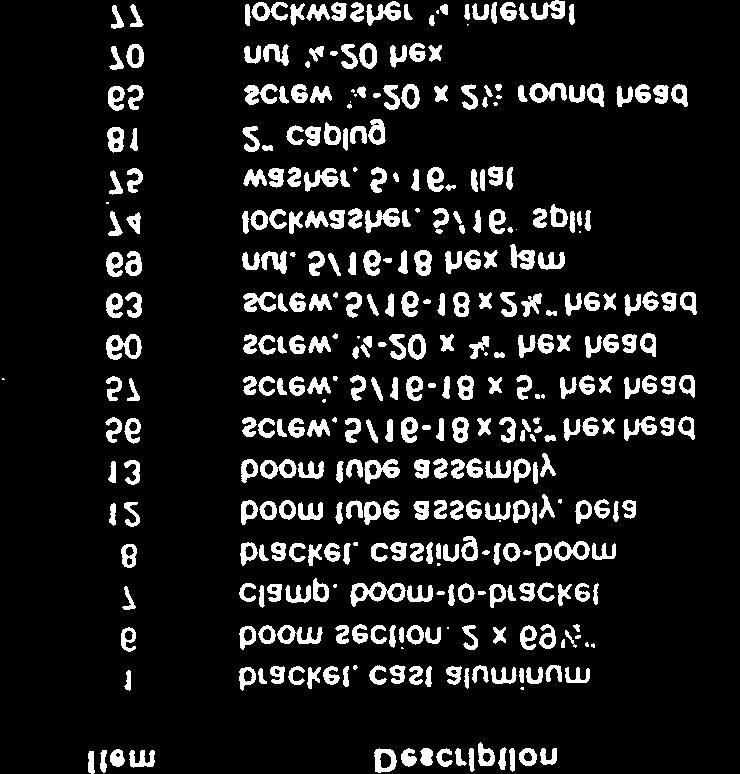
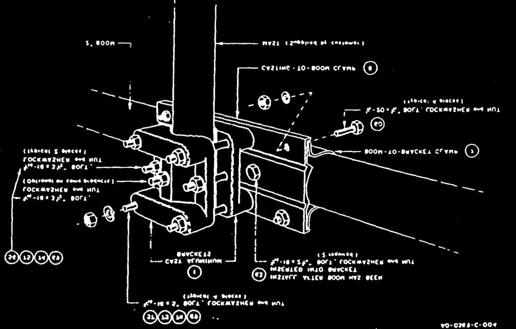
2 Compression Clamps Take care when measuring the tubing lengths for your mode of transmission Place the., clamp near the end of the tube with the joint even with the slot in the tube. Tighten the clamp until the inner tube cannot be turned in the outer tube. The compression clamps and their associated hardware are shown in Figure 7. Do not tighten the compression clamps until Instructed to do so. NOTE: To save time, loosely assemble all of the compression clamps and their appropriate hardware before beginning further installation of the antenna. Assembly Of The Boom Select the two halves of the boom brackets (items 7 & 8) and the two cast aluminum mast clamps (item 1) and loosely assemble as shown in Figure 4. Select the four boom sections (items 6, 12 & 13) 2" diameter tubing. Slip the unswaged end of the long boom section (items 12 & 13) into the boom-to-mast bracket (items 7 & 8) and line up the holes. Secure the boom sections to the bracket using the two 5/16"- 18 x 2 3/4" bolts (item 63), nuts (item 69) and lockwashers (item 74) provided. Do not tighten at this time. The bracket must be loose to facilitate mounting the antenna on NOTE: The reflector end of the boom (item 12) has a small hole drilled 71 1/8" from the unswaged end. This hole must be positioned so it is facing up (skyward) when the boom is assembled. The hole will be used for attaching the beta match in a later step. Refer to Figure 4. Slip the remaining boom section (item 6) over the swaged end of the assembled boom section (items 12 & 13) and secure using the ¼ -20 x 2 ½ bolt (item 65), nut (item 70) and lockwasher (item 77) as shown in Figure 4. NOTE: The boom-to-mast brackets have a hole through their center to allow securing to the mast with the 5/16"-18 x 3 1/2" bolt. It is recommended that the mast be removed and a 11 /32" hole be drilled at the desired mast clamp position, the reinstall the mast. If this is not possible, the clamp will hold its position on the mast in all but
3 AO-0226-C-004 Figure
4 Pre-assembling The. : Element-to-Boom center of Brackets On The. Select a. large sized set of element-t.-boom brackets.(item 4) marked. with a number. Pre-assemble the brackets on the reflector end of the boom about 18 1/2" from the the boom-to-mast clamps. The reflector end of the boom can be identified by the Select a small sized element-to-boom bracket (item 2) marked with a number 4 and loosely assemble, on the reflector end of the boom 75" from the driven element brackets that you assembled earlier. Refer to Figure 5B. These brackets will be the 10-meter reflector brackets. DO NOT TIGHTEN. Select a set of medium sized element-to-boom brackets (item 3 marked with a number 13 and loosely assemble on the reflector end of the boom as shown in Figure 5B. Assemble the bracket 3 inches from the end of the boom to the center of the bracket. This pair of brackets will be for the meter reflector. Assembly of boom Meter Reflector NOTE: The following steps will be in singular form. Do them first for one side of the then for the other side. Select the "15-20 Ref" tubing bundle (item 36). Insert the thick-walled end of the R1 ( t 1/4" x 95 1/2") into the element-to-boom bracket (item 3) assembled on the boom. Tighten the screws to hold the element securely but do not tighten the anchor screws Check to see that the meter reflector element will lie in a plane parallel to the earth when the antenna is mounted on the mast. This can be done by observing the position of the reflector element with respect to the boom-to-mast bracket and then adjusting the reflector element accordingly. Recheck the 3" measurement from the end of the boom to the center of the bracket then tighten the anchor screws
5 Select a 1'/4 compression clamp (item 48) and its' associated screw (item 80) and nut (item 68) and assemble as shown in Figure 7. NOTE: Figure 7 shows all the compression clamps with their associated hardware. The drawing is full size to aid you in identifying the parts. Lay the part over the proper drawing for easy identification. Slip the assembled compression clamp over the end of the R1 section (item 39). Select the R2 section (1 1/8 x 38") and slip the unswaged end into the R1 section. At this time, you must decide which mode of transmission you will use either Lo Phone. Hi Phone or CW. Measure the dimension of R2 for your mode of transmission as shown in Figure 6. The measurement is made from the end of R1 to the end of R2. CAUTION When you have selected your mode of transmission (Lo Phone. Hi Phone or CW). you must use the same mode for remaining measurements. Do not attempt to use averages or various combinations of setting measurements on the same element, or serious deterioration in antenna performance will result. the VSWR charts shown in Figure 3 should help you to decide which mode to select. Assemble a 1" compression clamp (item 49) as shown in Figure 7. Slip the assembled clamp over the end of R2. Select the 15-meter parasite trap and slip the unswaged end into the R2 section with drain hole down. CAUTION - There are two style 15- and 10-meter traps. Observe the part number marking closely, as shown in Figure 6. The Driven Element traps are different internally than the parasitic element traps. Measure 1" from the end of the R2 section to the edge of the plastic trap cap as shown in Figure 6. Now. tighten the compression clamp SLIGHTLY. Assemble a '/z" compression clamp (item 45) as shown in Figure 7. Slip the assembled clamp over the end of the 15-meter trap. Select the R3 section (item 37, 7 /16" x 37") and slip it into the 15-meter trap. Measure dimension of R3 for your mode of transmission as shown in Figure 6. Tighten compression clamp SECURELY. Carefully recheck all your measurements then tighten the compression clamps SECURELY. Select the "10 Ref" tubing bundle (item 32) and slip the unswaged end of the R2-1 section (item 35. %" x 55") into the bracket (item 2) assembled on the boom. Tighten the screws to hold the element securely but do not tighten the anchor screws at this Check to see that the 10-meter reflector will lie in the same plane as the meter reflector and carefully recheck the 48" measurement from the center of the one reflector bracket to the center of the other reflector bracket. Now tighten the anchor screws SECURELY. Assemble the remainder of the 10-meter reflector in the same manner as you did the 1520 meter reflector. Refer to Figures 5, 6 and 7 for illustrations.
6 ( ) Select the DE1 section(31) (1 ¼ x 48") from the Driven Element tubing bundle (26) Slip a Driven Element insulator (85) on the unslotted end of the DE1 section. Then slip the insulated end of DE I into the bracket assembled on the boom. Tighten the screws to hold the element securely but do not tighten the anchor screws at this time. ( ) Check to see that the Driven Element will lie in the same plane as the Reflector elements already installed. Carefully re-check the 75" measurement from the center of the 10-meter Reflector bracket to the center of the Driven Element bracket then tighten the anchor screws SECURELY. ( ) Assemble a 1 1/4" compression clamp (48) as shown in Figure 7. Slip the assembled clamp over the Dc t section Select the DE2 section (29) (1 ¼ x 42") and slip the unswaged end into the DE1 section. Measure the DE2 dimension for your mode of transmission as shown in Figure 6 then tighten the compression clamp ( ) Assemble a 1" compression clamp (49) as shown in Figure 7. Slip the assembled clamp over the end of the DE2. ( ) Select the 10-meter Driven Element trap (44). If you look closely at the trap. you will notice that the part number is marked near one end. This is the SHORTED end of the trap. Slip the SHORTED end of the trap into the DE2 section (29) and measure 1 " from the end of DE2 to the plastic trap cap as shown in Figure 6. Now tighten the compression clamp SLIGHTLY. ( ) Assemble two t" compression clamps (49) and slip them on each end of the DE3 section (30) (1 x 5") positioning them near each end. Slip the DE3 section ever the 10- meter trap (44) then slip the unswaged end of the 15-meter Driven Element trap (42) into the DE3 sections. Keeping the DE3 section approximately equidistant from the two traps. measure the DE3 dimension for your mode of transmission as shown in Figure 6. Now tighten the compression clamps SLIGHTLY. ( ) Assemble a 1/2" compression clamp (45) as shown in Figure 7 and slip it over the swaged end of the 15-meter trap. Select the DE4 section (27) (7/16 x 28") and slip it into the 15-meter trap. Measure DE4 dimension for your mode of transmission as shown in Figure 6. then tighten compression clamp SLIGHTLY. ( ) Carefully re-check all dimensions then tighten the compression clamps SECURELY ( ) Select the Beta Match tubes (28) (36 x 38 3/4"). Beta shorting wire (5) (1/8" formed wire) and the beta supporting insulator (83) and clamps (84) as shown in Figure 8. Attach the shorting wire to the beta tubes using the two x' h" screws (61) square nuts (68) and lockwashers (78). Assemble the beta tubes on the boom as shown in Figure 8. using four x 2" screws (79). nuts (68) and lockwashers (78) but do not tighten the screws at this time. ( ) Select the beta shorting clip and secure to the end of the beta shorting wire using a x 1/2" screw (61) nut (65) and lockwasher (78). Attach the shorting clip to the boom using a No. 10 sheet metal screw and lockwasher (66) & (78). Now tighten all screws SECURELY.
7 Select a set of small element-to-boom brackets (item 2), marked with a number 4. and LOOSELY assemble them on the boom 73"from the center of the driven element bracket to the center of the 10-meter director bracket as shown in Figure 5 and 6. Select the "No. 10 Dir" tubing bundle (item 23) and assemble it on the boom in the same manner as you did the previous elements. Refer to Figures 5.6 and 7. Make certain the 10meter Director lies in the same plane as the other elements and carefully recheck the 73" dimension before tightening the bracket anchor screws securely.
INSTRUCTION MANUAL for MODEL TH6-DX "THUNDERBIRD" (389)
") INSTRUCTION MANUAL for MODEL TH6-DX "THUNDERBIRD" (389) HY-GAIN ELECTRONICS CORPORATION, N. E. Hwy #6 at Stevens Creek, Lincoln, Nebraska 65801 Telephone 434-6331 INTRODUCTION Ely-Gain's new Model TH6-DX
INSTRUCTION MANUAL for MODEL TH6-DX "THUNDERBIRD" (389) HY-GAIN ELECTRONICS CORPORATION, N. E. Hwy #6 at Stevens Creek, Lincoln, Nebraska 65801 Telephone 434-6331 INTRODUCTION Ely-Gain's new Model TH6-DX
MODEL DB-1015A 10- and 15-Meter Duo-Band Antenna Order No. 330
 MODEL DB-1015A 10- and 15-Meter Duo-Band Antenna Order No. 330 HY-GAIN ELECTRONICS CORPORATION 8601 Northeast Highway 6 Lincoln, Nebraska 68505 Telephone 464-9151 Area Code 402 TABLE OF CONTENTS page SECTION
TELEX. iiilhiijiri INSTRUCTION MANUAL ORDER NO. 411 TELEX COMMUNICATIONS, INC ALDRICH AVE SO. MINNEAPOLIS. MN U.SA.
 TELEX. iiilhiijiri TELEX COMMUNICATIONS, INC. 9600 ALDRICH AVE SO. MINNEAPOLIS. MN 55420 U.SA. INSTRUCTION MANUAL ORDER NO. 411 Base Station, 5-Element Beam Antenna This antenna is a five element, Citizens
LJ element beam for 10 or 12 meters INSTRUCTION MANUAL. CAUTION: Read All Instructions Before Operating Equipment
 LJ-113 3 element beam for 10 or 1 meters INSTRUCTION MANUAL CAUTION: Read All Instructions Before Operating Equipment 308 Industrial Park Road Starkville, MS 39759 USA Tel: 66-33-9538 Fax: 66-33-6551 VERSION
INSTRUCTION MANUAL VB-66DX. 6-Meter 6-Element Beam. Preparation For Assembly. General Description
 VB-66DX 308 Industrial Park Road Starkville, MS 39759 USA Ph: (662) 323-9538 FAX: (662) 323-6551 6-Meter 6-Element Beam INSTRUCTION MANUAL General Description The Hy-Gain Model 66DX is a full sized 6-
INSTRUCTION MANUAL. Specifications Electrical. Front-To-Back Ratio VSWR at Resonance Less than 1.5:1 Nominal Impedance. Mechanical
 300 Industrial Park Road, Starkville, MS 39759 Ph: (662) 323-8538 FAX: (662) 323-6551 TH-3JRS Tri-band HF 3 Elements Beam Covers 10, 15 and 20 Meters INSTRUCTION MANUAL WARNING Installation of this product
TELEX, liutiiilio"i TELEX COMMUNICATIONS, INC ALDRICH AVE. SO. MINNEAPOLIS. MN USA
 TELEX, liutiiilio"i TELEX COMMUNICATIONS, INC. 9600 ALDRICH AVE. SO. MINNEAPOLIS. MN 55420 USA INSTRUCTION MANUAL ORDER NO. 410 General This antenna is a five-element, Citizens Band beam with a forward
DB Duo-Monoband Beam 7 - Element, 12 and 17 Meter INSTRUCTION MANUAL. General Description
 308 Industrial Park Road Starkville, MS 39759 USA Ph: (662) 323-9538 FAX: (662) 323-6551 DB- 1217 Duo-Monoband Beam 7 - Element, 12 and 17 Meter INSTRUCTION MANUAL General Description The Hy-Gain DB-1217
Cushcraft. Amateur Radio Antennas LFA-6M5EL. 6 Meter 5 Element Loop Feed Antenna INSTRUCTION MANUAL
 Cushcraft Amateur Radio Antennas LFA-6M5EL 6 Meter 5 Element Loop Feed Antenna INSTRUCTION MANUAL CAUTION: Read All Instructions Before Operating Equipment VERSION 1A Cushcraft Amateur Radio Antennas 308
INSTRUCTION MANUAL. Model 18AVQII Five Band Vertical Antenna 10, 15, 20, 40, 80 Meter. General Description. Theory of Operation
 Model 18AVQII Five Band Vertical Antenna 10, 15, 20, 40, 80 Meter 308 Industrial Park Road Starkville, MS 39759 (662) 323-9538 Fax: (662) 323-5803 INSTRUCTION MANUAL General Description The Hy-Gain 18AVQII
INSTRUCTION MANUAL. Specifications Mechanical. 1 5/8 to 2 1/16 O.D. (41mm to 52mm)
") 308 Industrial Park Road Starkville, MS 39759 USA Ph: (662) 323-9538 FAX: (662) 323- General Description Model VB-25FM 2-Meter 5 Elements Beam INSTRUCTION MANUAL This antenna is a 5-element, 2-meter beam
308 Industrial Park Road Starkville, MS 39759 USA Ph: (662) 323-9538 FAX: (662) 323- General Description Model VB-25FM 2-Meter 5 Elements Beam INSTRUCTION MANUAL This antenna is a 5-element, 2-meter beam
Cushcraft. Amateur Radio Antennas DB-46M8EL. Dual band 6 and 4 Meter, 8 Element Beam Antenna INSTRUCTION MANUAL
 Cushcraft Amateur Radio Antennas DB-46M8EL Dual band 6 and 4 Meter, 8 Element Beam Antenna INSTRUCTION MANUAL CAUTION: Read All Instructions Before Operating Equipment VERSION 1B Cushcraft Amateur Radio
Model VB-23FM 2-Meter 3-Element Beam
 308 Industrial Park Road Starkville, MS 39759 USA Ph: (662) 323-9538 FAX: (662) Model VB-23FM 2-Meter 3-Element Beam [ INSTRUCTION MANUAL Figure 1 Overall View and Boom Detail GENERAL DESCRIPTION This
DIR-73K. Discoverer 73 Director 40-Meter Kit for DIS-72. Instruction Manual
 DIR-73K Discoverer 73 Director 40-Meter Kit for DIS-72 Instruction Manual 308 Industrial Park Road Starkville, MS 39759 USA PH: 662-323-9538 FAX: 662-323-6551 TABLE OF CONTENTS Page General Description......1-1
INSTRUCTION MANUAL ORDER NO. V3R MODEL V3R. Collinear Gain Vertical for MHz
 ORDER NO. V3R MODEL V3R Collinear Gain Vertical for 216-225 MHz INSTRUCTION MANUAL General Description The new Hy-Gain V3R VHF antenna is a collinear 5/8-wave omnidirectional vertical antenna for the 216-225
M2 Antenna Systems, Inc. Model No: 20M5LD
 M2 Antenna Systems, Inc. Model No: 20M5LD SPECIFICATIONS: Model... 20M5LD Frequency Range... 14.0 14.350 MHz *Gain (Full Band)... 10.2 dbi Typical Front to back... 23 db Typical Beamwidth... E=50 / H=66
MOSLEY DIPOLE CONVERSION KIT MODEL TA-40-KR
 MOSLEY DIPOLE CONVERSION KIT MODEL TA-40-KR TO CONVERT MODELS TA-31, TA-32, TA-33 AND TA-36 FOR OPERATION ON 40 METERS The high performance of your MOSLEY Antenna can only be achieved if the antenna is
INSTRUCTION MANUAL. Model VB-215DX MECHANICAL DESIGN GENERAL DESCRIPTION ELECTRICAL DESIGN. 2 Meter 15 Element Yagi for SSB/CW
 Model VB-215DX 2 Meter 15 Element Yagi for SSB/CW INSTRUCTION MANUAL GENERAL DESCRIPTION The Hy-Gain Model 215DX is a high performance yagi antenna for SSB/CW DXing in the Amateur 2 meter band. It features
TELEX COMMUNICATIONS, INC ALDRICH LIVE SO. MINNEAPOLIS. MN U S A. /~g-~~~~r iu IORDER NO. 337s
 IkEfEX N TELEX COMMUNICATIONS, INC. 300 ALDRICH LIVE SO. MINNEAPOLIS. MN 55420 U S A /~g-~~~~r iu IORDER NO. 337s MAN A I MODEL V4S Collinear Gain Vertical for 420450 MHz PN801910 General Description The
INSTRUCTION MANUAL. Model 18AVQII Five Band Vertical Antenna 10, 15, 20, 40, 80 Meter
 Model 18AVQII Five Band Vertical Antenna 10, 15, 20, 40, 80 Meter 308 Industrial Park Road Starkville, MS 39759 (662) 323-9538 Fax: (662) 323-5803 INSTRUCTION MANUAL General Description The Hy-Gain 18AVQII
Directive Systems & Engineering 2702 Rodgers Terrace Haymarket, VA
 Directive Systems & Engineering 2702 Rodgers Terrace Haymarket, VA 20169 1628 www.directivesystems.com 703 754 3876 K1JX DESIGNED 6 ELEMENT 50 MHZ YAGI, DSEJX6 50 INTRODUCTION The Directive Systems DSEJX6-50
M2 Antenna Systems, Inc. Model No: 20M6-125
 M2 Antenna Systems, Inc. Model No: 20M6-125 SPECIFICATIONS: Model... 20M6-125 Frequency Range... 14.0 14.350 MHz *Gain, (FS) / Over gnd... 11.19dBi / 16.6dBi @70 Front to back... 25 db Typical Beamwidth...
Assembly Instructions: Bencher Skylark
 Assembly Instructions: Bencher Skylark Tools Required: Pop Rivet Tool Tape Measure Hex Wrenches Screwdriver Several Disposable Rags Two Saw Horses Several boxes or bowls to hold fasteners and small parts
INSTRUCTION MANUAL V-42R. Dual Band Collinear Gain Vertical for MHz and GENERAL DESCRIPTION
 308 Industrial Park Road, Starkville, MS 39759 USA Ph: (662) 323-9538 FAX: (662) 323-6551 V-42R Dual Band Collinear Gain Vertical for 144-148 MHz and 436-450 INSTRUCTION MANUAL GENERAL DESCRIPTION The
TZ-RD-1740 Rotary Dipole Instruction Manual
 TZ-RD-1740 17/40m Rotary Dipole Instruction Manual The TZ-RD-1740 is a loaded dipole antenna for the 40m band and a full size rotary dipole for the 17m band. The antenna uses an aluminium radiating section
MA5B 20 / 17 / 15 / 12 / 10 Meter Beam Antenna
 ASSEMBLY AND INSTALLATION INSTRUCTIONS NE 20 / 17 / 15 / 12 / 10 Meter Beam Antenna 951485_GF_AB WARNING THIS ANTENNA IS AN ELECTRICAL CONDUCTOR. CONTACT WITH POWER LINES CAN RESULT IN DEATH, OR SERIOUS
K1FO 12 ELEMENT 144/147 MHz YAGI
 K1FO 12 ELEMENT 144/147 MHz YAGI WARNING: INSTALLATION OF THIS PRODUCT NEAR POWER LINES IS DANGEROUS. FOR YOUR SAFETY FOLLOW THE INSTALLATION DIRECTIONS. Ariane Arrays, Inc. Copyright 2006 201 Hopedale
INSTALLATION INSTRUCTIONS
 INSTALLATION INSTRUCTIONS Trans4mer Grille Guard/Winch Mount Kit 645 For Chevrolet Silverado 500HD & 3500 This WARN Trans4mer system can be customized to give your Chevy Silverado a wide variety of looks,
M2 Antenna Systems, Inc. Model No: 40M3L
 M2 Antenna Systems, Inc. Model No: 40M3L SPECIFICATIONS: Model... 40M3L Frequency Range... 7.0-7.3 MHz X 150 khz Gain... 6.6 dbi Front to back... 23 db Beamwidth... E=62 Feed type... Hair pin match Feed
Easy Step by Step Manual
 Easy Step by Step Manual Teletower Mini XL Wall-Floor installation The tower packages #1-#2-#3 Open Base Package #1 for the main tower parts. Here you see the three tower tubes (H-Head, M-Middle, F-Feed)
PAC-12 Kit Contents. Tools Needed Soldering iron Phillips screwdriver Wire stripper Wrenches, 7/16 and 1/2 Terminal crimp tool Pliers Solder
 PAC-2 Kit Contents Part Quantity Screws: 8/32 x 3/8 Screws: 8-32 x 5/6 Screw: 8-32 x /4 #8 internal tooth washers #8 solder lug ring terminals Bolt: Aluminum, /4-20 x.5 /4 internal tooth washer Nut: Aluminum
MFJ-2982 Feather-Lite 80-6 Meter Vertical Antenna
 MFJ-2982 Feather-Lite 80-6 Meter Vertical Introduction: The MFJ-2982 is a lightweight 31-foot fiberglass antenna designed to mount on any convenient post, mast, or a suitable wide-stance tripod such as
AV-12AVQ Triband HF Vertical 10, 15, 20-Meter INSTRUCTION MANUAL
 308 Industrial Park Starkville, MS 39759 USA Ph: (662) 323-9538 FAX: (662) 323-6551 AV-12AVQ Triband HF Vertical 10, 15, 20-Meter INSTRUCTION MANUAL General Description This vertical antenna is designed
Cushcraft. Amateur Radio Antennas BOLP Element 5 Band Optimized Log Periodic Antenna INSTRUCTION MANUAL
 Cushcraft Amateur Radio Antennas BOLP-1013 13 Element 5 Band Optimized Log Periodic Antenna INSTRUCTION MANUAL CAUTION: Read All Instructions Before Operating Equipment VERSION 1A Cushcraft Amateur Radio
M2 Antenna Systems, Inc. Model No: KT34XA TO KT36XA UPGRADE KIT
 M2 Antenna Systems, Inc. Model No: KT34XA TO KT36XA UPGRADE KIT SPECIFICATIONS: SPECIFICATIONS for the KT34-6XA MODEL NUMBER...KT36XA FREQ. RANGE...14.0-14.35 MHz 21.0-21.45 MHz 28.0-29.0 MHz GAIN (Free
Projector Ceiling Mount
 INSTALLATION MANUAL Projector Ceiling Mount PID:3010 PID:5466 20kg (44lbs) RATED CAUTION: DO NOT EXCEED RATED LISTED WEIGHT. SERIOUS INJURY OR PROPERTY DAMAGE MAY OCCUR! ISSUED: FEB. 2013 NOTE: Read the
A Folding 5-Element Yagi for 144 MHz
 A Folding 5-Element Yagi for 144 MHz Steve Kavanagh, VE3SMA, April 2017 1. Introduction I have found antennas which fold up quickly to take less space in the car to be useful in VHF/UHF portable operating.
Assembly Aid. One of the packages contains the required bolts, washers and nuts for final assembly
 Assembly Aid Open the box and arrange the pieces similar to what you see here. Assembly instructions as well as the list of tools required for assembly are also in the box. One of the packages contains
Side-of-Pole Mount for 4 Modules (SPM4) For Module Type B ASSEMBLY INSTRUCTIONS. step-by-step assembly and installation
 For Module Type B ASSEMBLY INSTRUCTIONS. step-by-step assembly and installation") Side-of-Pole Mount for 4 Modules (SPM4) For Module Type B ASSEMBLY INSTRUCTIONS step-by-step assembly and installation Version 1, Rev A SP3358-2 PCN 060712-5 Side-of-Pole Mount for 4 Modules (SPM4) For
Side-of-Pole Mount for 4 Modules (SPM4) For Module Type B ASSEMBLY INSTRUCTIONS step-by-step assembly and installation Version 1, Rev A SP3358-2 PCN 060712-5 Side-of-Pole Mount for 4 Modules (SPM4) For
ULTRA SPACE SAVER SQUARED Installation Instructions
 Installation Instructions The Ultra Space Saver Squared has several steps for installation. Note that the single and double sided setups and parts are different. Make sure you follow the instructions according
SS1062, SS10621 & SS10621E Free Standing PWC & Fishing Boat Hoist SS1062 SS10621 SS10621E
 SS1062, SS10621 & SS10621E Free Standing PWC & Fishing Boat Hoist SS1062 SS10621 SS10621E Midwest Industries, Inc. Page 1 Ida Grove, IA 51445 800.859.3028 www.shorestation.com 0003231 REV A 1/25/05 Bundles
LIGHT BEAM ANTENNA MaxRange Antenna Series Assembly Instructions MaxRange Plus Digital / High Definition Television Antennas
 LIGHT BEAM ANTENNA MaxRange Antenna Series Assembly Instructions MaxRange Plus Digital / High Definition Television Antennas Assembly Instructions 1 MaxRange Plus Antenna These instructions will lead you
M2 Antenna Systems, Inc. Model No: YAGI ANTENNA
 M Antenna Systems, Inc. Model No: 4.5-7 YAGI ANTENNA SPECIFICATIONS: Model... 4.5-7 Frequency Range... 4.0 To 4.5 MHz *Gain... 0 To 7 dbi Front to back... 0 db over the rear 80 Beamwidth... E=44 H=50 typical
M2 Antenna Systems, Inc. Model No: 2M7
 M2 Antenna Systems, Inc. Model No: 2M7 SPECIFICATIONS: Model... 2M7 Frequency Range... 144 To 148 MHz *Gain... 12.3 dbi Front to back... 20 db Typical Beamwidth... E=43 H=50 Feed type... T Match Feed Impedance....
W6NL Moxon on Cushcraft XM240
 W6NL Moxon on Cushcraft XM240 0 db = 10.73 dbi 7.050 MHz 2.00 99.5% Efficiency High F/B 300+ khz VSWR BW SWR 1.50 1.00 7 7.1 7.2 7.3 MHz - 1 - Construction of W6NL Moxon on Cushcraft XM240 Dave Leeson,
M2 Antenna Systems, Inc. Model No: 40M2L
 M2 Antenna Systems, Inc. Model No: 40M2L SPECIFICATIONS: Model...40M2L Frequency Range...6.9-10 MHz X 150 khz Gain...5.5 dbi Front to back...13 15 db Beamwidth...E=74 Feed type...hair pin match Feed Impedance....50
SAFETY THIS PRODUCT IS FOR OFFROAD USE ONLY. ALL LIABILITY FOR INSTALLATION AND USE RESTS WITH THE OWNER.
 SAFETY Your safety and the safety of others is very important. In order to help you make informed decisions about safety, we have provided installation instructions and other information. These instructions
C O R P O R A T I O N
 ASSEMBLY AND INSTALLATION INSTRUCTIONS A4S 20 / 5 / 0 MeterBeam C O R P O R A T I O N 95279 (8/98) WARNING THIS ANNNA IS AN ELECTRICAL CONDUCTOR. CONTACT WITH POWER LINES CAN RESULT IN DEATH, OR SERIOUS
Side-of-Pole Mount for 4 Modules (SPM4) For Module Type D
 For Module Type D") Side-of-Pole Mount for 4 Modules (SPM4) For Module Type D ASSEMBLY INSTRUCTIONS step-by-step assembly and installation Version 1, Rev A PCN 060712-7 Side-of-Pole Mount for 4 Modules (SPM4) For Module Type
Side-of-Pole Mount for 4 Modules (SPM4) For Module Type D ASSEMBLY INSTRUCTIONS step-by-step assembly and installation Version 1, Rev A PCN 060712-7 Side-of-Pole Mount for 4 Modules (SPM4) For Module Type
Installation Job Aid (English) for Avaya WLAN 8100 series- WLAN AP 8120 with External Antenna
 for Avaya WLAN 8100 series- WLAN AP 8120 with External Antenna") Release 3.0 NN47251-311 Issue 02.01 June 2014 Installation Job Aid (English) for Avaya WLAN 8100 series- WLAN AP 8120 with External Antenna How to get help To access the complete range of services and
Release 3.0 NN47251-311 Issue 02.01 June 2014 Installation Job Aid (English) for Avaya WLAN 8100 series- WLAN AP 8120 with External Antenna How to get help To access the complete range of services and
INSTALLATION INSTRUCTIONS
 STRIP DOORS AIR DOORS INSTALLATION INSTRUCTIONS BULK PVC FILM STRIP SHEET PANEL SCREENS, CURTAINS and ENCLOSURES MEGA-PRO SWINGING DOORS DOCK ACCESSORIES IMPORTANT Carefully examine the carton(s) for damage.
Cisco Aironet Dual-Band MIMO Wall-Mounted Omnidirectional Antenna (AIR-ANT2544V4M-R)
") Cisco Aironet Dual-Band MIMO Wall-Mounted Omnidirectional Antenna (AIR-ANT2544V4M-R) This document outlines the specifications for the Cisco Aironet 2.4-GHz/5-GHz Dual-Band MIMO Wall-Mounted Omnidirectional
Cisco Aironet Dual-Band MIMO Wall-Mounted Omnidirectional Antenna (AIR-ANT2544V4M-R) This document outlines the specifications for the Cisco Aironet 2.4-GHz/5-GHz Dual-Band MIMO Wall-Mounted Omnidirectional
Assembly Instructions for model: VMPR1
 Assembly Instructions for model: VMPR1 Congratulations on your purchase! The VMPR1 ceiling mount provides a unique, simplified method of ceiling mounting inverted LCD/DLP projectors. Its low profile design
For additional assistance call
 The following pages will help guide you through the process of assembling your new 48 custom prize wheel. Choose an assembly area with plenty of room to lay your pieces on the floor and also a bench or
M2 Antenna Systems, Inc. Model No: 2M5WL
 M2 Antenna Systems, Inc. Model No: 2M5WL SPECIFICATIONS: Model... 2M5WL Frequency Range... 144 To 148 MHz *Gain... 16.84 dbi Front to back... 22 db Typical Beamwidth... E=26 H=29 Feed type... T Match Feed
Hiniker Company th St. P.O. Box 3407 Mankato, MN VEHICLE INSTALLATION INSTRUCTIONS FOR: CHEV/GMC 4x4: K1500 SILVERADO/SIERRA
 VEHICLE INSTALLATION INSTRUCTIONS FOR: CHEV/GMC x: 007 03 K500 SILVERADO/SIERRA Page of 5 Hiniker Company 58766 0th St. P.O. Box 307 Mankato, MN 5600 INSTRUCTION SHEET NO: 505 Rev. A August 0, 03 IMPORTANT:
JK-65 Five Element 6M Yagi
 JK-65 Five Element 6M Yagi PO Box 266, Croton Falls, NY 10519-0266 845.228.8700 (TEL) 845.279.5526 (FAX) info@jkantennas.com Page 1 of 8 JK Antennas Limited Warranty and Liability JK Antennas ( Manufacturer
Gared Pro-S Portable Backstop
 Models: 9616 & 9618 Installation, Operation and Maintenance Instructions Please read all instructions before attempting installation or operation of these units SAVE THESE INSTRUCTIONS FOR FUTURE USE PUBLICATION
LIGHT BEAM ANTENNA MaxRange Antenna Series Assembly Instructions MaxRange Ultra Digital / High Definition Television Antennas
 LIGHT BEAM ANTENNA MaxRange Antenna Series Assembly Instructions MaxRange Ultra Digital / High Definition Television Antennas Assembly Instructions 1 MaxRange Ultra Antenna These instructions will lead
MFJ Instruction Manual Table of Contents
 Table of Contents MFJ-1768 Introduction...2 Choosing a Location for the Antenna...2 Tools and Time Requirements...3 MFJ-1768 Parts List...3 Safety Precautions...3 Assembly and Installation...4 Tuning...7
INSTALLATION INSTRUCTIONS
 INSTALLATION INSTRUCTIONS Trans4mer Grille Guard/Winch Mount For Chevrolet Silverado 1500HD & 2500 Kit 68162 This WARN Trans4mer system can be customized to give your Chevy Silverado a wide variety of
Range height adjustable assembly
 Table of contents Digital handset operation 3 Height adjustable bench kit 4-5 Cable carrier 6 Ganging tray and ganging rail 7 Height adjustable return frame kit 8 Cable entry pole 9 24 and 30 d worksurfaces
TOYOTA TUNDRA CARGO DIVIDER Preparation. Part Number: PT
 Preparation Part Number: PT767-34070 Kit Contents 1 1 Divider Screen 2 1 LH Bracket with Warning Label 3 1 RH Bracket without Warning Label NOTE: Part number of this accessory may not be the same as the
THIS SHOULD TWEAK YOUR IMAGINATION
 10-27-05 THIS SHOULD TWEAK YOUR IMAGINATION SPECIFICATIONS FOR SINGLE ANTENNA MODEL NUMBER... 432EME-12 FREQUENCY... 430-436 MHz GAIN... 14.4 dbd FRONT TO BACK... 23 db VSWR... 1.2:1 TYPICAL BEAMWIDTH...
In the box: Figure 1: Instructions, 1-channel, 2 retainers, 2 adjustable tubes, 1 chrome ring, and hardware. Channel
 1 P a g e Thunder Mounts Garage Systems The Overhead Garage Mount Solution The World s Leader of Multi-fit Overhead Garage Mount Safety and Technology. Overhead Garage Door Opener Mounting Instructions.
ULTRA SPACE SAVER Installation Instructions
 Installation Instructions The Ultra Space Saver has several steps for installation. Note that the single and double sided setups and parts are different. Make sure you follow the instructions according
HAPPY TRAILS PRODUCTS
 Thank you for purchasing Happy Trails products. Our products are proudly hand made in Boise Idaho, USA. If you have any questions or concerns about the installation of this product, please contact us directly
Build a 12/17 Meter Trap Dipole Phil Salas AD5X
 Build a 12/17 Meter Trap Dipole Phil Salas AD5X Introduction Why a 12/17 meter rotatable dipole? Well, many folks have verticals for the lower bands, and multi-band dipoles or beams for 20-, 15-, and 10
CSS Central Mount System
 CSS-20 Installation Manual CSS-20 Safety Notifications Below are the installation instructions for the CSS-20-2 Long Span Beam Mounting System. Please read these safety notifications prior to beginning
Instructions and Parts List DR-12N Martin House
 Form 36-99 Instructions and Parts List DR-N Martin House Note: It is necessary to install a post before house is put up, but the house can be assembled at any time. House parts Check parts against this
CEILING-MOUNTED MONORAIL ANCHOR TRACK SYSTEM Assembly and Operation Instruction Manual
 CEILING-MOUNTED MONORAIL ANCHOR TRACK SYSTEM Assembly and Operation Instruction Manual This manual is for various mounting types and plain and trussed track profiles. ISO 9001:2008 Registered Manual 103-0075
C-3S, C-3S/D, C-3S/H, C3S/HH
 Strike Force Classic 3-Band C-3S, C-3S/D, C-3S/H, C3S/HH 20, 15 and 10 Meter (plus 17 & 12) Multi-monoband Yagi Antenna FREQUENCY COVERAGE: 13.950-14.400; 21.000-21.450; 1.1 MHz of 10 Meters (VSWR
User Guide. For. Alpha Antenna ProMaster
 User Guide For Alpha Antenna ProMaster Manufactured by: Alpha Antenna 1.888.482.3249 Website: http://alphaantenna.com User Guide Version 2.5 October 2, 2016 Page 1 Introduction Thank you for your support
INSIDE PANEL NOT SHOWN TO DETAIL ANCHORING SYSTEM
 SIX INCH ALPHA MODULE INSTALLATION KEWAUNEE SCIENTIFIC CORPORATION SIX INCH ALPHA MODULE ANCHORING SYSTEM After Alpha module has been set in desired location. Adjust the four adjustment bolts until the
INSTALLATION INSTRUCTIONS
 INSTALLATION INSTRUCTIONS Trans4mer Grille Guard/Winch Mount Kit 37133 (Black) for Ford Ranger As you read these instructions, you will see NOTES, CAUTIONS and WARNINGS. Each message has a specific purpose.
DP-100 half wave Dipole Antenna Manual
 DP-100 half wave Dipole Antenna Manual 1. Introduction: A dipole antenna is a radio antenna that can be made of aluminum, copper, and bronze tube with a center-fed driven element. It consists of two metal
Mast and Antennas for Field Day & Emergencies
 Mast and Antennas for Field Day & Emergencies John A. Allocca, WB2LUA, July 2005 This is a 27 feet 1.5 diameter portable guyed mast with a 28 feet diameter footprint. It breaks down into four 6 feet sections
hy-gain INSTRUCTION MANUAL AV-18HT Hy-Tower Vertical Antenna 10,15,20,40, and 80 Meters Specifications Mechanical
 hy-gain 308 Industrial Park Road Starkville, MS 39759 USA Ph: (662) 323-9538 FAX: (662) 323655 1 INSTRUCTION MANUAL AV-18HT Hy-Tower Vertical Antenna 10,15,20,40, and 80 Meters General Description The
ASSEMBLY AND INSTALLATION INSTRUCTIONS R , 12, 15, 17, 20, 30, 40 Meters (5/99) COMMUNICATIONS ANTENNAS
 COMMUNICATIONS ANTENNAS") ASSEMBLY AND INSTALLATION INSTRUCTIONS R7000 10, 12, 15, 17, 20, 30, 40 Meters COMMUNICATIONS ANTENNAS 951465 (5/99) WARNING THIS ANTENNA IS AN ELECTRICAL CONDUCTOR. CONTACT WITH POWER LINES CAN RESULT
ASSEMBLY AND INSTALLATION INSTRUCTIONS R7000 10, 12, 15, 17, 20, 30, 40 Meters COMMUNICATIONS ANTENNAS 951465 (5/99) WARNING THIS ANTENNA IS AN ELECTRICAL CONDUCTOR. CONTACT WITH POWER LINES CAN RESULT
Sales & Service. JFK - Just For Kids. sasportonline.com. 135 Forestview Road 7879 Will Rogers Blvd.
 Sales & Service sasportonline.com SA Sport (Canada) SA Sport (U.S.A.) 135 Forestview Road 7879 Will Rogers Blvd. P.O. Box 40 Fort Worth, Texas Orillia, Ontario USA 76140 Canada L3V 6H9 Telephone: (705)
LPR System Installation instructions
 Toll LPR System Installation instructions 1 General Information The following installation instructions should be used as a guide for installing Folding Guard LPR System. Good common sense and appropriate
SAFETY THIS PRODUCT IS FOR OFFROAD USE ONLY. ALL LIABILITY FOR INSTALLATION AND USE RESTS WITH THE OWNER.
 SAFETY Your safety and the safety of others is very important. In order to help you make informed decisions about safety, we have provided installation instructions and other information. These instructions
Directive Systems & Engineering 2702 Rodgers Terrace Haymarket, VA
 Directive Systems & Engineering 2702 Rodgers Terrace Haymarket, VA 20169-1628 www.directivesystems.com 703-754-3876 25 Element 7.4 wl. K1FO Designed Yagi, Model DSEFO432-25 ELECTRICAL SPECIFICATIONS Frequency
JK NAVASSA-5. 5-Band Yagi (20M/17M/15M/12M/10M) Optional 6M Add-on Kit Available
 Optional 6M Add-on Kit Available") JK NAVASSA-5 5-Band Yagi (20M/17M/15M/12M/10M) Optional 6M Add-on Kit Available 72 Grays Bridge Road, Unit D, Brookfield, CT 06804 845.228.8700 (TEL) 845.279.5526 (FAX) info@jkantennas.com Last Updated:
JK NAVASSA-5 5-Band Yagi (20M/17M/15M/12M/10M) Optional 6M Add-on Kit Available 72 Grays Bridge Road, Unit D, Brookfield, CT 06804 845.228.8700 (TEL) 845.279.5526 (FAX) info@jkantennas.com Last Updated:
M2 Antenna Systems, Inc. Model No: 2MCP22
 M2 Antenna Systems, Inc. Model No: 2MCP22 SPECIFICATIONS: Model... 2MCP22 Frequency Range... 144 To 148 MHz *Gain... 14.39 dbic Front to back... 25 db Typical Elipticity... >3db Beamwidth... 38 Feed type...
M2 Antenna Systems, Inc. Model No: KT31WARC
 M2 Antenna Systems, Inc. Model No: KT31WARC SPECIFICATIONS: Model... KT31WARC Frequency Range... 10.1-10.15 MHz **Selectable Frequency Range... 14.0-14.35 MHz **Selectable... (175 KHz / 2:1 VSWR Nominal)
M2 Antenna Systems, Inc. Model No: 10-30LP8
 M2 Antenna Systems, Inc. Model No: 10-30LP8 VSWR 2:1 TYPICAL VSWR @ 70 FT. 2:1 1.5:1 1.5:1 1.2:1 1.2:1 10 14 MHz 11 12 13 17 15 16 18 19 20 21 22 23 24 25 26 27 28 29 30 SPECIFICATIONS: Model...10-30LP8
INSTRUCTION SHEET. PIECE INVENTORY - MOBILE BASES Refer to the diagram for part identification.
 INSTRUCTION SHEET D2260 HEAVY-DUTY MINI-MOBILE BASE D2057 HEAVY-DUTY MOBILE BASE D2058 SUPER HEAVY-DUTY MOBILE BASE D2259 EXTENSION KIT FOR D2260/D2057 D2246 EXTENSION RAIL KIT FOR D2058 This Shop Fox
**MOUNTING YOUR MONITOR
 FPP72V200 72 FREE STANDING DISPLAY CART Assembly Instructions Hardware List Ref. Qty. Part No. Description AA 4 030-1128 1/4-20 UNC, 1 3/4 Socket Hd Screws BB 1 030-1129 5/8-11 UNC 1 3/4 Socket Hd Screw
Strata. urniture. Mission Rim Instructions. Parts in the Arm Box: Parts in the Body Box:
 1A Watch our assembly videos at www.strataf.com/videos.html Parts in the Arm Box: Arm - Outside View Arm - Inside View Corbels x 4 1B Parts in the Body Box: Back Deck x 1 Seat Deck x 1 with the Feet attached
INSTALLATION INSTRUCTIONS FOR HAND OPERATED MODELS: 170, 171-R, 171-N, 172, 260
 INSTALLATION INSTRUCTIONS FOR HAND OPERATED MODELS: 170, 171-R, 171-N, 172, 260 I. SUSPENDED INSTALLATIONS NOTE: MODEL 260 FENSTEEL TRACK IS ASSEMBLED IN THE SAME MANNER AS DESCRIBED BELOW WITH THE EXCEPTION
ALUMINUM FOOTBALL GOALS INSTRUCTIONS WARNING WARNING Upright. Upright. Flag. Flag. Offset Pole.
 ALUMINUM FOOTBALL GOALS INSTRUCTIONS 800-67-090 Flag Flag Ground Sleeve Anchor Kit WARNING Football goals are shipped unassembled. Read all instructions thoroughly before attempting to assemble this equipment.
METAL BENDER OPERATING & MAINTENANCE INSTRUCTIONS Model Nos: CCB1 & CCB2 Part Nos: & CCB2 CCB1
 METAL BENDER Model Nos: CCB1 & CCB2 Part Nos: 7630073 & 7630074 CCB2 CCB1 OPERATING & MAINTENANCE INSTRUCTIONS 1206 1 The Compact Bender allows you to economically make a variety of bends in flat, square,
Topo Freestanding Applications - Private Office
 4 3 2 Topo Freestanding Applications - Private Office Combo Wrench If you have a problem, question, or request, call your local dealer, or Coalesse at 1.800.627.6770 Or visit our website: www.coalesse.com
Gared Pro Portable Backstop
 Models: 5016, 5017, & 5018 Installation, Operation and Maintenance Instructions Please read all instructions before attempting installation or operation of these units PUBLICATION NO. 551754436 SAVE THESE
Strata. urniture. Adriana Instructions. Parts in the Arm Box: Parts in the Body Box: Watch our assembly videos at
 1A Watch our assembly videos at www.strataf.com/videos Parts in the Arm Box: Arm - Outside View Arm - Inside View 1B Parts in the Body Box: Back Deck x 1 Seat Deck x 1 with the Feet attached Back Panel
Please read BOTH these Installation Instructions and the General Instructions before attempting to install or operate this equipment.
 Please read BOTH these and the General Instructions before attempting to install or operate this equipment. 1. Blue Ox towing products and accessories are intended to be installed by Blue Ox Dealers who
User Guide. For. Alpha Antenna ProMaster Sr. Civilian Military Systems
 User Guide For Alpha Antenna ProMaster Sr Civilian Military Systems Manufactured by: Alpha Antenna 1.888.482.3249 Website: http://alphaantenna.com User Guide Version 2.5 March 17, 2017 Page 1 Introduction
CTTR Tire Rack Required tools
 CTTR Tire Rack Required tools Torque wrench, ratchet, 9/16 socket, tape measure, and square edge. ASSEMBLY REQUIREMENTS *Torque all T-bolt nuts to 35-40 foot pounds. Failure to follow the assembly instructions
User Instructions Multiline Otter Scoreboard Caddy Assembly
 List of parts: User Instructions Multiline Otter Scoreboard Caddy Assembly Single Caddy Double Caddy 1 1 Base assembly with attached wheels 2 4 1 1 2 4 4 8 10 20 12 Uprights (60 or 74 aluminum extrusion)