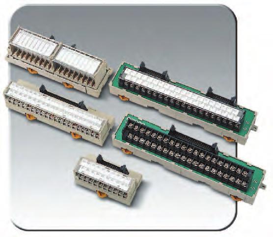
BA 商品多樣化 商品多樣性的介紹 可以和感應器和指示燈等各種元件連接的端子台模組 有 點型 ( 輸入 ) 點型 ( 輸入 輸出 ) 0 點型 ( 輸入 輸出 ) 等種類 可以不經由繼電器轉接而可以和空氣閥和電磁閥等直接連接的 00mA 開關型式 配備可簡單進行動作確認的 LED 指示燈 DIN 軌
|
|
|
- Marcus Leonard
- 5 years ago
- Views:
Transcription


1 e.enproteko.com BA 型連接端子系列 用一對纜線傳送多數個信號的省配線 模組備有多樣化系列產品 依各類需求 可自由自在做應用組合 益 成 h 自 H ttp ://s 動控 ale 制.en 材 pro 料 tek 行 o.c om 特 長 一對纜線連接 輸入 / 輸出機器最遠可達 00m B A 型 連 接 端 子 系 列 Q 使用前 配線作業及維修之效率化 防止配線錯誤 削減成本 縮短工時 Q 使用後 應 用 實 例 機器內模組相互連接 省配線 和 PLC 操作部間的省 配線 加工 Robrot 等移動的 省配線 個橾作盤分離較遠時 的省配線 懸吊式 Pendant 操作部 與本體間的省配線
")
 0 點型 ( 輸入 輸出 ) 等種類 點型 W0 D0 H.")
 可節省空間之薄長型的 hybrid IC 型式 有 點型 ( 輸入 輸出 ) 輸入型 W D H0mm 輸出型 W D H0mm 傳送遲延時間有標準型 (TYP.l.")
 利用 ONE TOUCH 連接方式可接續到 OMRON SYSMACPLC 及三菱電機製 PLC 的 PLC 連結器 SYSMACPLC 用有 點型 ( 輸入 輸出 ) 點型")
, 可對應感應器等的高速應答 符合 IP 的耐環境性及節省工數之感應器 I/O 連結器型式 對應 0 點的輸入信號 可在有水氣處使用, 符合 IP 規格的防浸形 對應光電開關")

2 BA 商品多樣化 商品多樣性的介紹 可以和感應器和指示燈等各種元件連接的端子台模組 有 點型 ( 輸入 ) 點型 ( 輸入 輸出 ) 0 點型 ( 輸入 輸出 ) 等種類 可以不經由繼電器轉接而可以和空氣閥和電磁閥等直接連接的 00mA 開關型式 配備可簡單進行動作確認的 LED 指示燈 DIN 軌道 螺絲裝設共用型式 將配備 點繼電器型式 ( 輸出 ) 新增至系列內 輸出入一體成型的輸出入混合型式 輸入 點 / 輸出 點及輸入 點 / 輸出 點等種類 輸入可對應有接點 無接點 配備可簡單進行動作確認的 LED 指示燈 DIN 軌道 螺絲裝設共用型式 可安裝在 PCB 基板, 且不必選擇裝設場所的模組型 有 點型 ( 輸入 輸出 ) 0 點型 ( 輸入 輸出 ) 等種類 點型 W0 D0 H.mm 0 點型 W D0 Hmm 的迷你尺寸 傳送遲延時間有標準型 (TYP..ms) 高速型 (TYP. ms) 可節省空間之薄長型的 hybrid IC 型式 有 點型 ( 輸入 輸出 ) 輸入型 W D H0mm 輸出型 W D H0mm 傳送遲延時間有標準型 (TYP.l.ms) 高速型 (TYP. ms) 利用 ONE TOUCH 連接方式可接續到 OMRON SYSMACPLC 及三菱電機製 PLC 的 PLC 連結器 SYSMACPLC 用有 點型 ( 輸入 輸出 ) 點型 ( 輸入 輸出 ) 三菱電機製 PLC 用有 點型 ( 輸入 輸出 ) 提昇和 PLC 連接時之作業的效率化 防止配線錯誤 降低成本 傳送遲延時間有標準型 (TYP..ms) 高速型 (TYP. ms), 可對應感應器等的高速應答 符合 IP 的耐環境性及節省工數之感應器 I/O 連結器型式 對應 0 點的輸入信號 可在有水氣處使用, 符合 IP 規格的防浸形 對應光電開關 近接開關 極限開關之感應器 I/O 連結器連接 配備可簡單進行動作確認的 LED 指示燈 DIN 軌道 螺絲裝設共用型式 e. 實現 點單位之分散控制的 B A bit chain 型式 將分散配置之輸出入機器的信號整體傳送至 BA 型 bit chain 的傳送路可以很簡單地以專用壓接連結器來進行配線 位址自動分配, 不需要手動設定 BA 型及 BA 型間的最長傳送距離為 00m,BA 型及 BT 子局間的最長傳送距離為 00m,BT 子局間的最長傳送距離為 0m 可節省控制盤內空間及節省工數的 PLC 模組 把 BA 機能模組化成為 CQM C00H/C00HS 之模組 可使配線作業更有效率, 也可節省盤內的空間 H B A 商品多樣化
 由開關設定 NPN 對應輸入 +- 交互 BAS-TBS 型 I/O 區別配線 type 形狀傳送遲延時間輸入形態 +- 端子構成型式 鎖螺絲端子 標準 (TYP.")
 NPN 對應輸入 - BA-TA 型 * +- 交互 BA-TB 型 * NPN 對應輸入 +- 交互 BA-TC 型 NPN 對應輸入 - BA-TA 型 * +- 交互")
 高速 (TYP.")
3 BA 型一覽表 種類 點型 I/O 區別配線 type 形狀傳送遲延時間輸入形態 +- 端子構成型式 輸入 ( 送信 ) 點型 鎖螺絲端子 標準 (TYP..ms)/ 高速 (TYP.ms) 由開關設定 NPN 對應輸入 +- 交互 BAS-TBS 型 I/O 區別配線 type 形狀傳送遲延時間輸入形態 +- 端子構成型式 鎖螺絲端子 標準 (TYP..ms) 高速 (TYP.ms) NPN 對應輸入 - BA-TA 型 * +- 交互 BA-TB 型 * NPN 對應輸入 +- 交互 BA-TC 型 NPN 對應輸入 - BA-TA 型 * +- 交互 BA-TB 型 * NPN 對應輸入 +- 交互 BA-TC 型 H B A 一覽表型 輸入 ( 送信 ) 模組式 小型模組 標準 (TYP..ms) 高速 (TYP.ms) 標準 (TYP..ms) 高速 (TYP.ms) 高速 (TYP.ms) NPN 對應 +- 交互 TTL 入力 BAS-TB 型 BAS-TB 型 BA-TD 型 BA-TD 型 NPN 入力 BA-TD-D 型 hybrid IC 標準 (TYP..ms) 高速 (TYP.ms) e. CMOS 入力 BAH-TD 型 BAH-TD 型
 ) NPN 集極開路 00mA/ 點 NPN 集極開路 00mA/ 點 * PNP 集極開路 00mA/ 點 PNP 集極開路 00mA/ 點 * NPN 集極開路 00mA/ 點 NPN 集極開路 00mA/ 點 * PNP 集極開路 00mA/ 點 PNP 集極開路 00mA/ 點 * 標準 TYP. (.ms) NPN 集極開路高速 00mA/ 點 TYP.")
 HOLD LOAD OFF HOLD LOAD OFF HOLD LOAD OFF HOLD LOAD OFF HOLD LOAD OFF HOLD LOAD OFF HOLD LOAD OFF HOLD LOAD OFF HOLD LOAD OFF HOLD LOAD OFF HOLD LOAD OFF * + - + - +- 交互 BA-RB BA-RB BA-RC BA-RC")
4 BA 一覽表型 I/O 區別配線型式形狀傳送遲延時間輸出形態錯誤時輸出處理正負端子構成型式 輸出 ( 送信 ) 鎖螺絲端子 模組式 標準 TYP. (.ms 高速 TYP. ( ms ) ) NPN 集極開路 00mA/ 點 NPN 集極開路 00mA/ 點 * PNP 集極開路 00mA/ 點 PNP 集極開路 00mA/ 點 * NPN 集極開路 00mA/ 點 NPN 集極開路 00mA/ 點 * PNP 集極開路 00mA/ 點 PNP 集極開路 00mA/ 點 * 標準 TYP. (.ms) NPN 集極開路高速 00mA/ 點 TYP. ( ms) 標準 TYP. (.ms) NPN 集極開路高速 0mA/ 點 TYP. ( ms) HOLD LOAD OFF HOLD LOAD OFF HOLD LOAD OFF HOLD LOAD OFF HOLD LOAD OFF HOLD LOAD OFF HOLD LOAD OFF HOLD LOAD OFF HOLD LOAD OFF HOLD LOAD OFF HOLD LOAD OFF * 交互 BA-RB BA-RB BA-RC BA-RC BA-RF BA-RF BA-R BA-R BA-RB BA-RB BA-RC BA-RC BA-RF BA-RF BA-R BA-R BAS-RB BAS-RB BAS-RB BAS-RB BA-RA BA-RA H 小型模組 高速 (TYP.ms) NPN 集極開路 0mA/ 點 HOLD LOAD OFF * BA-RA-D e. B A 一覽表型 hybrid IC 標準 TYP. (.ms) CMOS 輸出高速 ma/ 點 TYP. ( ms) HOLD LOAD OFF * BAH-RD BAH-RD. HOLD : 錯誤時, 保持錯誤發生前之輸出狀態 LOAD OFF: 錯誤時, 輸出全部 OFF( 遮斷 ). HOLD/LOAD OFF 由 H/L 端子的結線, 為選擇方式. N channel MOS-FET open drain 輸出. P channel MOS-FET open drain 輸出 I/O 區別 Relay 區別形狀額定電壓傳送遲延時問錯誤時輸出處理型式 輸出 ( 受信 ) Relay 輸出 Power-MOS FET Relay 輸出 DC (a ) 標準 (TYP..ms) HOLD LOAD OFF HOLD LOAD OFF 0D-RR-BA 0D-RR-BA 0D-RM-BA 0D-RM-BA
 高速 (TYP.")
 NPN 對應輸入 NPN 對應輸入 NPN 對應輸入 BA-TE BA-TE BA-TE BA-TE BA-E-M BA-E-M H")
 高速 (TYP.")

 標準 (TYP.")
 由開關設定 NPN 對應輸入 NPN 集極開路 00mA/ 點 HOLD/ LOAD OFF 由 Switch 設定 BAM-BS")
 NPN 對應輸入 NPN 集極開路 00mA/ 點 NPN 對應輸入 NPN 集極開路 00mA/ 點 HOLD LOAD OFF")
 NPN 對應輸入 NPN 集極開路 00mA/ 點 HOLD LOAD OFF BAM-B BAM-B 感應器 I/O 連接器型式")
5 BA 型一覽表 連接器型式 I/O 區別配線型式形狀傳送遲延時間輸入形態型式 輸出 ( 受信 ) PLC Connector 點 type PLC Connector 點 type 標準 (TYP..ms) 高速 (TYP.ms) 標準 (TYP..ms) 高速 (TYP.ms) 標準 (TYP..ms) 高速 (TYP.ms) NPN 對應輸入 NPN 對應輸入 NPN 對應輸入 BA-TE BA-TE BA-TE BA-TE BA-E-M BA-E-M H B A 一覽表型 I/O 區別配線型式形狀傳送遲延時間輸出形態錯誤時輸出處理型式 輸入 ( 送信 ) PLC Connector 點 type PLC Connector 點 type 輸入 / 輸出混合型 標準 (TYP..ms) 高速 (TYP.ms) 標準 (TYP..ms) 高速 (TYP.ms) 標準 (TYP..ms) 高速 (TYP.ms) NPN 集極開路 0mA/ 點 NPN 集極開路 0mA/ 點 NPN 集極開路 0mA/ 點 HOLD LOAD OFF HOLD LOAD OFF HOLD LOAD OFF HOLD LOAD OFF HOLD LOAD OFF HOLD LOAD OFF BA-RA BA-RA BA-RA BA-RA BA-RA BA-RA BA-RA BA-RA BA-RA-M BA-RA-M BA-RA-M BA-RA-M 配線型式形狀傳送遲延時間輸入 / 輸出形態錯誤時處理型式 鎖螺絲端子 ( 輸入 點 / 輸出 點 ) 標準 (TYP..ms) 高速 (TYP.ms) 由開關設定 NPN 對應輸入 NPN 集極開路 00mA/ 點 HOLD/ LOAD OFF 由 Switch 設定 BAM-BS e. 鎖螺絲端子 ( 輸入 點 / 輸出 點 ) 標準 (TYP..ms) NPN 對應輸入 NPN 集極開路 00mA/ 點 NPN 對應輸入 NPN 集極開路 00mA/ 點 HOLD LOAD OFF BAM-B BAM-B BAM-F 高速 (TYP.ms) NPN 對應輸入 NPN 集極開路 00mA/ 點 HOLD LOAD OFF BAM-B BAM-B 感應器 I/O 連接器型式 (0 點 ) 配線型式形狀傳送遲延時間輸入形態 Connector 配列型式 感應器 I/O 連接器型式 (M) TYP..ms TYP..ms TYP.ms 可切換 TYP..ms TYP.ms 可切換 NPN 對應輸入 NPN 對應輸入 A 型式 BAC-T0A 型 BAC-T0A-A 型 BAC-T0A-B 型
 NPN 對應輸入 ( 線式感應器接續不可 ) - BA-T0S * +- 交互 BA-T0S * 模組式 標準 (TYP..ms) TTL 輸入 BA-T0M * I/O 區別配線型式形狀傳送遲延時間輸入形態錯誤時輸出處理 +- 端子構成型式.")
 NPN 集極開路 00mA/ 點 NPN 集極開路 0mA/ 點 HOLD - BA-R0SC0 HOLD BA-R0MC I/O 區別配線型式形狀傳送遲延時間錯誤時輸出處理型式 輸入 / 輸出 ( 送信 ) e.")
6 BA 一覽表型 0 點型式 I/O 區別配線型式形狀傳送遲延時間輸入形態 +- 端子構成型式 輸入 ( 送信 ) 鎖螺絲端子 標準 (TYP..ms) NPN 對應輸入 ( 線式感應器接續不可 ) - BA-T0S * +- 交互 BA-T0S * 模組式 標準 (TYP..ms) TTL 輸入 BA-T0M * I/O 區別配線型式形狀傳送遲延時間輸入形態錯誤時輸出處理 +- 端子構成型式. 0 點型式 BA-T0S 型和 BA-T0S 型端子構成不同 輸出 ( 送信 ) 鎖螺絲端子 模組式 bit chan terminal 標準 (TYP..ms) 標準 (TYP..ms) NPN 集極開路 00mA/ 點 NPN 集極開路 0mA/ 點 HOLD - BA-R0SC0 HOLD BA-R0MC I/O 區別配線型式形狀傳送遲延時間錯誤時輸出處理型式 輸入 / 輸出 ( 送信 ) e. BT 子局 台 標準 (TYP..ms)/ 高速 (TYP.ms)* LOAD BA 型 H B A 一覽表型.輸入 / 輸出可以切換. 標準 (TYP..ms) 和 高速 (TYP. ms) 可以切換
 點 標準 (TYP..ms)/ 高速 (TYP.")
 * HOLD/ LOAD OFF ( 輸入 only) * HOLD/ LOAD OFF * HOLD/ LOAD OFF * 輸入 CH 輸出 CH ( 合計 CH) 輸入 CH 輸入 CH")
 輸出 點 ( 點 埠 ) 輸入 點輸出 點 點 ( 點 埠 ) 標準")
 * HOLD/ LOAD OFF ( 輸入 only) * HOLD/ LOAD OFF ( 輸入 only) * HOLD/ LOAD OFF * 輸入 CH 輸出 CH 合計 CH (group")
 HOLD 輸入 CH ( 基本輸入輸出模組 ) C00H-BAI 型 輸出 點 ( 點 埠 ) e. 標準 ms) * 輸出 CH (group ) C00H-BA0 型 輸出 點標準 (TYP.")
7 BA 型一覽表 PLC 模組型式 CQM 型用 I/O 區別配線型式形狀傳送遲延時間錯誤時輸出處理 I/Q 占有 CH 型式 輸入 / 輸出 輸入 輸入 輸出 輸出 輸入 點輸出 點 點 ( 點 埠 ) 點 點 ( 點 埠 ) 點 標準 (TYP..ms)/ 高速 (TYP.ms) * 標準 (TYP..ms)/ 高速 (TYP.ms) * 標準 (TYP..ms)/ 高速 (TYP.ms) * 標準 (TYP..ms)/ 高速 (TYP.ms) * 標準 (TYP..ms)/ 高速 (TYP.ms) * HOLD/ LOAD OFF ( 輸入 only) * HOLD/ LOAD OFF * HOLD/ LOAD OFF * 輸入 CH 輸出 CH ( 合計 CH) 輸入 CH 輸入 CH CQM-BA 型 CQM-BA 型 CQM-BA 型 輸入 CH CQM-BA0 型 輸入 CH CQM-BA0 型 H B A 一覽表型 PLC 模組型式 C00HS/H 型用 * I/O 區別配線型式形狀傳送遲延時間錯誤時輸出處理 I/Q 占有 CH 型式 輸入 / 輸出 輸入 / 輸出 輸入 輸入 點 ( 點 埠 ) 輸出 點 ( 點 埠 ) 輸入 點輸出 點 點 ( 點 埠 ) 標準 (TYP..ms)/ 高速 (TYP.ms) * 標準 (TYP..ms)/ 高速 (TYP.ms) * 標準 (TYP..ms)/ 高速 (TYP.ms) * HOLD/ LOAD OFF ( 輸入 only) * HOLD/ LOAD OFF ( 輸入 only) * HOLD/ LOAD OFF * 輸入 CH 輸出 CH 合計 CH (group ) 輸入 CH 輸出 CH 合計 CH (group ) 輸入 CH (group ) C00H-BA 型 C00H-BA 型 C00H-BA 型 輸入 點標準 (TYP..ms) HOLD 輸入 CH ( 基本輸入輸出模組 ) C00H-BAI 型 輸出 點 ( 點 埠 ) e. 標準 (TYP..ms)/ 高速 (TYP.ms) * 輸出 CH (group ) C00H-BA0 型 輸出 點標準 (TYP..ms) 輸出 CH ( 基本輸入輸出模組 ) C00H-BA0 型. 標準 (TYP..ms) 和 高速 (TYP. ms) 可以切換. HOLD 和 LOAD OFF 可以切換. C00H-CPU0/0/0/ 不能使用 00

8 Cat. No. X0-E-0 Connector-terminal Conversion Unit roup Catalog e.
9 TABLE OF CONTENTS XWD/XWC/XWB/XWE Connector-Terminal Block Conversion Units (with Special Connecting Cables) XWD Slim Connector-Terminal Block Conversion Units XWC Connector-Terminal Block Conversion Units with Two-tiered I/O Terminal Block with Common XWC Connector-Terminal Block Conversion Units with Common XWE Connector-Terminal Block Conversion Units with Three-tiered Terminal Block with Common 0 XWB Through-type Connector-Terminal Block Conversion Units XWZ Connecting Cables for Connector-Terminal Block Conversion Units XWB Servo Relay Units XWB Terminal Blocks for Motion Control Units XWZ Host Link Cables (RS-C Cables for Programmable Controllers) XWF Connector-Terminal Block Conversion Units with -point Terminal Block with Common and Screwless Terminals XWN Connector-Terminal Block Conversion Units with -input e-con Terminal Block with Common e.

10 Connector-Terminal Block Conversion Units (with Special Connecting Cables) XWD/XWC/ XWB/XWE Connector-Terminal Block Conversion Units use a Cable to connect all PLC inputs and outputs at once. Wiring and installation time are cut and maintenance is simpler. e. Features Slim Connector-Terminal Block Conversion Units contribute to downsizing control panels and automatic equipment. XWD Mounting area reduced by % (in comparison with 0-pole XWB Units.) Fallout prevention for terminal screws. Terminal screws arranged by color to simplify counting terminal numbers and ensure more efficient wiring. Refer to pages to. An extensive series with Connector-Terminal Block Conversion Units for a wide range of applications. XWB Series includes both Through-type Connector-Terminal Block Conversion Units, as well as Special Servo Relay Units and Terminal Blocks for Motion Controls Units. Refer to pages to. Common terminal and LED operation indicators provided on terminal block. XWC Common terminal for device power supply on Units with twotiered terminal block. For inputs only. Refer to pages to. Three-tiered terminal block equipped with power supply common for easy input device connection. XWE Power supply common provided for input devices. Three-tiered terminal block simplifies wiring. Refer to pages 0 to.
11 Connector-Terminal Block Conversion Unit Connection Examples Note: Refer to page for Position Control Unit and Servo Driver connections. Controller Connections XWD Series (See page.) Programmable Controller I/O Units with Terminal Blocks, Board Computers, Etc. EZD Multiple-point Temperature Controller Series ES00 Temperature Controllers (for Expansion I/O) Cable with Discrete-wire Crimp Terminals XWZ-00 XWZ-00C e. XWD-0 SYSMAC CM/C-series Motion Control Unit Connections XWB Motion Control Unit Terminal Block (See page.) XWD-0 XWD- SYSMAC CM/C-series Motion Control Unit C00-MC (two axes) C00-MC (four axes) XWB-0J- XWZ-00J-F (Two-/four-axis Connecting Cable) XWZ-00J-F (Two-/four-axis Connecting Cable) XWB-0J- Programmable Controller and Host Link Connection XWZ Host Link Cable (See page.) SYSMAC PLC CQM C Series C Series CM XWZ-@@@P/R/S/T Host Link Cable Host Personal computer Factory Intelligent Terminal Programmable Terminal Connector-Terminal Block Conversion Units XWD/XWC/XWB/XWE
 to contribute to downsizing control panels and automatic equipment. Fallout prevention for terminal screws.")
12 Slim Connector-Terminal Block Conversion Units XWD New Slim Connector-Terminal Block Conversion Units. Mounting area reduced by % (in comparison with 0- pole XWB Units) to contribute to downsizing control panels and automatic equipment. Fallout prevention for terminal screws. Round or forked crimp terminals can be used. Mount to DIN Track or via screws. Unique DIN Track lock can maintain open status during DIN track attachment and removal. Terminal cover can be locked open. Screw terminals are arranged by color in groups of five to simplify counting terminal numbers. Ratings and Characteristics e. Rated current A Rated voltage AC, DC Insulation resistance 00 MΩ min. (at 00 DC) Dielectric strength 00 AC for min (leakage current: ma max.) Operating temperature 0 to C Ordering Information Mounted Connector No. of poles Model Dimension A Dimension B Mounted Connector model Cable Connector model XA 0 XWD-0 XA-0 XM-00-T MIL Connectors XWD- 00 XA- XM-0-T 0 XWD-0 0 XA-0 XM-00-T XWD-0-RF 0 XA-0 XM-00-T (See note.) XWD-0-RM 0 XA-0 XM-00-T (See note.) 0 XWD-0 XA-0 XM-00-T XC 0 XWD-0C XC-0 XM-00-U MIL Connectors XWD-C 00 XC- XM-0-U 0 XWD-0C 0 XC-0 XM-00-U 0 XWD-0C XC-0 XM-00-U MR Sockets 0 XWD-0X MR-0RFD MR-0M XWD-X 00 MR-RFD MR-M 0 XWD-0X MR-0RFD MR-0M MR Plugs 0 XWD-0Y MR-0RMD MR-0F XWD-Y 00 MR-RMD MR-F 0 XWD-0Y MR-0RMD MR-0F Note:. Has built-in bleeder resistance and is used for the CJW-ID/-ID.. Has built-in bleeder resistance and is used for the CJW-ID.. The MR Connector is made by Honda Tsushin Kogyo.
13 Dimensions Mounted Connector: XA MIL Connector A B XA MIL Connector Two,. dia. (.). Wiring Diagram (Example for Terminal Block with 0 Poles) Mounted Connector 0 0 (.) DIN Track lock.. M A A A A A A Connector pin No Connector pin No. B B B B B B Terminal Block Note: For all models, the odd-numbered pins on the Connector correspond to row A on the terminal block and the even-numbered pins Note: There is only one DIN Track lock located in the center of the terminal on the Connector correspond to row B on the block for a 0-pole Unit. terminal block. XWD-0-RF XWD-0-RM Connector (XA-0) Connector (XA-0) Terminal No. A A A A A A A A A A0 A A A A A A A A A A0 Terminal No. A A A A A A A A A A0 A A A A A A A A A A0 B B B B B B B B B B0 B B B B B B B B B B0 B B B B B B B B B B0 B B B B B B B B B B0 Terminal Block Terminal Block Note: The dimensions shown here are the same as the XWD-0.Note: The dimensions shown here are the same as the XWD-0. XWD-@@C Mounted Connector: XC MIL Connector XC MIL Connector A Two,. dia. B (.). Mounted Connector 0 0 e. Wiring Diagram (Example for Terminal Block with 0 Poles) DIN Track lock (.).. M A A A B B B A A A B B B Note: There is only one DIN Track lock located in the center of the terminal block for a 0-pole Unit. Terminal Block Note: For all models, the odd-numbered pins on the Connector correspond to row A on the terminal block and the even-numbered pins on the Connector correspond to row B on the terminal block. Slim Connector-Terminal Block Conversion Units XWD
14 Mounted Connector: MR Socket A B Two,. dia. (.). Wiring Diagram (Example for Terminal Block with 0 Poles) Mounted Connector DIN track lock (.).. M Note: There is only one DIN Track lock located in the center of the Connector for a 0-pole Unit. A B Two,. dia. (.). 0 0 Terminal Block Note: Connector pin numbers correspond -to- to terminal block numbers on all models. Wiring Diagram (Example for Terminal Block with 0 Poles) Mounted Connector DIN Track lock (.).. M e. XWD-@@Y Mounted Connector: MR Plug Note: There is only one DIN Track lock located in the center of the terminal block for a 0-pole Unit. Terminal Block Note: Connector pin numbers correspond -to- to terminal block numbers on all models. 0 0 Options (Sold Separately) Connecting Cables for Connector-Terminal Block Conversion Units Refer to pages to. Slim Connector-Terminal Block Conversion Units XWD

15 Connector-Terminal Block Conversion Units with Two-tiered I/O Terminal Block with Common XWC Common terminal provided. Use for either PLC Input Unit or Output Unit merely by changing short bar. Ordering Information No. of inputs No. of poles Model Mounted Connector model Cable Connector model 0 XWC-0-IO XA-0 XM-00-T Note: The Connecting Cable is the XWZ-@@@A described on page. Ratings and Characteristics Rated current Rated voltage Insulation resistance Dielectric strength Dimensions XWSC-0-IO A AC, DC Operating temperature 0 to C 00 MΩ min. (at 00 DC) 00 AC for min (leakage current: ma max.) 0 0 Wiring Diagram 0 Two,. dia. (.). Row B Row A Mounted Connector DIN Track lock (.) e A B A0 B0.. M + External power supply Terminal Block A + B A0 + B0 Either a PLC Input or Output Unit can be connected by shorting terminals A/B and A0/B0 to the + or terminals. Options (Sold Separately) Connecting Cables for Connector-Terminal Block Conversion Units Refer to pages to.
16 Precautions Correct Use XWD/XWC-0-IO Wiring Always turn OFF the power supply before wiring. Otherwise, cables or other conductors can short the terminals and cause the Unit to fail. Do not connect or disconnect Connectors with the power turned ON. Otherwise, it may cause malfunctions. Wiring Terminal Blocks Using Crimp Terminals (With a Terminal Block with M Screws) Round crimp terminals. mm dia. Forked crimp terminals Mounting Units to and Removing Units from DIN Track XW@ Connector-Terminal Block Conversion Units can be mounted side-to-side on DIN Track. Secure both ends of the XW@ with End Plates. When removing the Unit from a DIN Track, insert a flat-head screwdriver into the slider and pull the lock out.. mm max.. mm. mm max. e. Applicable crimp terminals Round crimp terminals.- Forked crimp terminals.y- Terminal Screw Tightening Torque Applicable wires AW to AW (0.0 to. mm ) AW to AW (0.0 to. mm ) Use a tightening torque of 0. N m when connecting wires or crimp terminals to the terminal block. Handling M Screw and Round Terminals Raise the M screw with a Phillips screwdriver as shown in diagram () and slide the screw toward you to keep the space open. Follow the steps in diagrams () and () below when using round crimp terminals. () () Connector-Terminal Block Conversion Units XWD/XWC
.")
17 Connector-Terminal Block Conversion Units with Common XWC Features like a common terminal and LED operation indicators reduce control panel wiring for input devices. Power supply common provided for input devices. LEDs indicate at a glance whether input signals are ON or OFF. Mounts to DIN Track or via screws. Connecting Cable available (sold separately). Ordering Information e. No. of inputs Input type Model NPN-compatible input (+ common) XWC-0-IN Ratings and Characteristics Rated current A/common Rated voltage to DC No. of circuits Input indicator LED (orange) Power supply voltage to DC±% range LED current DC: 0 ma/point max. Insulation resistance 0 MΩ min. (at 00 DC) Dielectric strength 00 AC for min Operating temperature 0 to C Dimensions XWSC-0-IN Two,. dia. Flat Cable Connector (MIL Plug) Terminal Block DIN Track lock... ().0. M. 0
18 Circuit and Terminal Arrangement Diagram Wiring Diagram Flat Cable Connector XA-0 (mating side) 0 0 Triangular mark External power supply Terminal Block SOURCE SOURCE Brown Blue (red) (black) Black (white) Brown Blue (white) (black) Note: Photoelectric and Proximity Sensor lead wire colors have changed in line with revisions to JIS standards. Former colors are given in parentheses ( ). + to DC e. Options (Sold Separately) Connecting Cables for Connector-Terminal Block Conversion Units Refer to pages to. Note: Do not use the -@C (TC Connector with Cable) because it is wired differently. Precautions Correct Use Photoelectric Sensor Proximity Sensor (-wire NPN output sensor with built-in amplifier) DC -wire Proximity Sensors Limit switches, etc. Wiring Always turn OFF the power supply before wiring. Otherwise, cables or other conductors can short the terminals and cause the Unit to fail. Do not connect or disconnect Connectors with the power turned ON. Otherwise, it may cause malfunctions. Wiring Terminal Blocks The following crimp terminals are applicable for terminal blocks with M. screws. -. (round) Y-. (forked) DIN Track Mounting Secure both ends of the XWC with End Plates. Terminal Screw Tightening Torque Use a tightening torque of 0. N m when connecting crimp terminals to the terminal block. Connector-Terminal Block Conversion Units (with Common) XWC

19 Connector-Terminal Block Conversion Units with Three-tiered Terminal Block with Common XWE A common terminal is provided for device power supply and the threetiered structure means easier wiring. For inputs only. The three-tiered terminal block simplifies wiring because the power supply terminal block is wired with just one crimp terminal. e. Ordering Information No. of inputs No. of poles Model Mounted Connector model Cable Connector model 0 XWE-0-IN XA-0 XM-00-T Ratings and Characteristics Rated current Rated voltage Insulation resistance Dielectric strength A to DC Operating temperature 0 to C 00 MΩ min. (at 00 DC) 00 AC for min (leakage current: ma max.) 0
20 0/ / /0 / / / / / 0/ / /0 / / / / / Dimensions XWE-0-IN XA-0 Two,.-dia. (mounting holes) Wiring Diagram... (terminal pitch) Mounted Connector External power supply Terminal Block Note: This is not a row of terminals. See note. e. Options (Sold Separately) Connecting Cables for Connector-Terminal Block Conversion Units Refer to pages to. Connector-Terminal Block Conversion Units with Three-tiered Terminal Block with Common XWE

21 Through-type Connector-Terminal Block Conversion Units XWB Simplifies Connector and terminal block replacement, and requires less in-panel wiring. Mount to DIN Track or via screws. MIL Flat Cable Connectors and Multi-pole, Square Connectors are standard. Terminal blocks available with either M or M. screws. Connecting Cables for Programmable Controllers available (sold separately). Connectors Type Model Connector Terminal Block Appearance Page Flat Cable XWB-@@ Flat Cable Connectors Terminal block with M screws SWB-@@ Terminal block with M. screws Twin-connector XWB-0-T Flat Cable Connectors Terminal block with M. screws Daisy Chain XWB-0-D Multi-pole, Squareconnector XWB-@@Y XWB-@@Y Multi-pole, Square Connector Plugs (See note.) Terminal block with M screws Terminal block with M. screws XWB-@@X Multi-pole, Square Connector Sockets (See note.) 0 Board I/O XWB-0F-P Board I/O Connectors (See note.) Terminal block with M. screws e. Note:. These Plugs and Sockets are made by Honda Tsushin Kogyo.. These Plugs are made by Fujitsu. Ratings and Characteristics Item Rated current Rated voltage Insulation resistance Dielectric strength A AC Operating temperature 0 to C XWB-@@@ Flat Cable Units 00 MΩ min. (at 00 DC) 00 AC for min (leakage current: ma max.) XWB-@@Y@ Multi-pole, Square-connector Units XWB-0F-P Board I/O Unit
22 OMRON's popular Connector-Terminal Block Conversion Unit line has two new additions that connect to -point I/O Units for Programmable Controllers. The new models offer reduced in-panel wiring and greater space savings. Twin-connector Units Refer to page. SYSMAC I/O Units Just one XWB-0-T Twinconnector Connector-Terminal Block Conversion Unit can be connect to a -point I/O Unit for a Programmable Controller. SYSMAC I/O Units e. XWB-0 XWB-0 XWB-0-T Daisy Chain Units Refer to page. SYSMAC I/O Units XWB-0-D Daisy Chain Units can distribute output signals from -point I/O Units for Programmable Controllers. XWB-0-D XWB-0-D Connector-Terminal Block Conversion Units (Through Type) XWB
23 Flat Cable Units with a Terminal Block with M Screws Dimensions XWB-@@. A Flat Cable Connector (MIL Plug)... Two,. dia. Wiring Diagram Flat Cable Connector (mating side) N N- N- N- Triangular mark Terminal Block (terminal side) Ordering Information Applicable Connectors N- N- No. of poles Model 0 XWB-0 XWB- 0 XWB-0 0 XWB-0 0 XWB-0 N N- Dimensions Note:. Either the XM-@@-N or the XM-@@-N may be used.. Each Connector requires two Semi-covers..0 Terminal Block e. Special Connecting Cables Refer to pages to. 0.. (.) Model No. of poles Dimension A (mm) Applicable Connector models (See note.) XWB-0 0. XA-0 XWB-. XA- XWB XA-0 XWB-0 0. XA-0 XWB XA-0 Note:. Flat Cable Connectors have one polarity slot.. Terminal block pitch is.0 mm. Use a wire size between 0. and. mm (AW to AW). The wire insertion holes are.. (H W) mm. Model Applicable Connectors (sold separately) Flat Cable Connectors, MIL Discrete-wire IDC Connectors, Double-row Sockets Sockets with Strain Reliefs Connectors (See note.) Semi-covers (See note.) XWB-0 XM-00-T XM-0-N XS-00 XM-0-N XWB- XM-0-T XM--N XS-0 XM--N XWB-0 XM-00-T XM-0-N XS-00 XM-0-N XWB-0 XM-00-T XM-0-N XS-0 XM-0-N XWB-0 XM-00-T XM-0-N XM-0-N XS-00 Connector-Terminal Block Conversion Units (Through Type) XWB
24 Flat Cable Units with a Terminal Block with M. Screws Dimensions XWB-@@. Flat Cable Connector (MIL Plug)... Two,. dia. Wiring Diagram Flat Cable Connector (mating side) N N- N- N- Triangular mark Terminal Block (terminal side) N- N- N N- Dimensions. Model No. of poles Dimension A (mm) XWB-0 0. XA-0 XWB- 0.0 XA- XWB XA-0 XWB-0 0. XA-0 XWB-0 0. XA-0 Note:. Flat Cable Connectors have one polarity slot.. Terminal block pitch is. mm.. Terminal Block 0. Applicable Connector models (See note.). (.) Ordering Information No. of poles Model 0 XWB-0 XWB- 0 XWB-0 0 XWB-0 0 XWB-0 Applicable Connectors Special Connecting Cables Refer to pages to. e. Model Flat Cable Connectors, MIL Sockets with Strain Reliefs XWB-0 XM-00-T XM-0-N XM-0-N XWB- XM-0-T XM--N XM--N XWB-0 XM-00-T XM-0-N XM-0-N XWB-0 XM-00-T XM-0-N XM-0-N XWB-0 XM-00-T XM-0-N XM-0-N Applicable Connectors (sold separately) Note:. Either the XM-@@-N or the XM-@@-N may be used.. Each Connector requires two Semi-covers. Discrete-wire IDC Connectors, Double-row Sockets Connectors (See note.) Semi-covers (See note.) XS-00 XS-0 XS-00 XS-0 XS-00 Connector-Terminal Block Conversion Units (Through Type) XWB
25 Twin-connector Units with a Terminal Block with M. Screws Dimensions XWB-0-T.. 0. Flat Cable Connector (MIL Plug: XA-0 ).. Two,. dia. Wiring Diagram.. Terminal Block Flat Cable Connector (mating side) Terminal Block (terminal side) 0.. (.) 0 0 DIN Track lock Triangular mark 0 0 Triangular mark Ordering Information Model Note:. The number of poles indicated here is the number of poles on the terminal block.. Flat Cable Connectors have one polarity slot.. Terminal block pitch is. mm. Applicable Connectors Note:. Either the XM-@@-N or the XM-@@-N may be used.. Each Connector requires two Semi-covers. Special Connecting Cables Refer to pages to. No. of poles (See note.) XWB-0-T 0 XA-0 Model e. Flat Cable Connectors, MIL Sockets with Strain Reliefs Applicable Connector models (See note.) XWB-0-T XM-00-T XM-0-N XM-0-N Applicable Connectors (sold separately) Discrete-wire IDC Connectors, Double-row Sockets Connectors (See note.) Semi-covers (See note.) XS-00 Connector-Terminal Block Conversion Units (Through Type) XWB
26 Daisy Chain Units with a Terminal Block with M. Screws Dimensions XWB-0-D.. Flat Cable Connector (MIL Plug: XA-0 ).. Two,. dia. Wiring Diagram Flat Cable Connector (mating side) 0 Terminal Block (terminal side).. Terminal Block DIN Track lock. (.) 0. Triangular mark 0 0 e. Triangular mark Ordering Information Model Note:. The number of poles indicated here is the number of poles on the terminal block.. Flat Cable Connectors have one polarity slot.. Terminal block pitch is. mm. Applicable Connectors Note:. Either the XM-@@-N or the XM-@@-N may be used.. Each Connector requires two Semi-covers. Special Connecting Cables Refer to pages to. No. of poles (See note.) XWB-0-D 0 XA-0 Model Flat Cable Connectors, MIL Sockets with Strain Reliefs Applicable Connector models (See note.) XWB-0-D XM-00-T XM-0-N XM-0-N Applicable Connectors (sold separately) Discrete-wire IDC Connectors, Double-row Sockets Connectors (See note.) Semi-covers (See note.) XS-00 Connector-Terminal Block Conversion Units (Through Type) XWB
27 Multi-pole, Square-connector Plug Units with a Terminal Block with M Screws Dimensions XWB-@@Y. A Multi-contact Connector (Plug)... Two,. dia. Wiring Diagram (Example for Terminal Block with 0 Poles) Multi-contact, Square Connector Terminal Block (mating side) (terminal side) 0 Note: All pins on the Multi-pole, Square Connector correspond -to- to the terminal of the same number on the terminal block as shown above. Ordering Information No. of poles Model 0 XWB-0Y XWB-Y 0 XWB-0Y Applicable Connectors 0 Dimensions Model Applicable Connectors (See note.) Hood (See note.) XWB-0Y MR-0F (soldered) MR-0L MRP-0F0 (crimped) (See note.) MR-0FW (wrapped) XWB-Y MR-F (soldered) MR-L MRP-F0 (crimped) (See note.) MR-FW (wrapped) XWB-0Y MR-0F (soldered) MRP-0F0 (crimped) (See note.) MR-0FW (wrapped) MR-0L Note:. All applicable Connector Hoods are made by Honda Tsushin Kogyo.. Use MRP-F or MRP-F0 crimp terminals made by Honda Tsushin Kogyo..0 Terminal Block e. DIN Track lock 0.. Model No. of poles Dimension A (mm) Applicable Connector models (See note.) XWB-0Y 0. MR-0RMD XWB-Y. MR-RMD XWB-0Y 0. MR-0RMD Note:. These Connectors are made by Honda Tsushin Kogyo.. Terminal block pitch is.0 mm. Use a wire size between 0. and. mm (AW to AW). The wire insertion holes are.. (H W) mm. Connector-Terminal Block Conversion Units (Through Type) XWB
28 Multi-pole, Square-connector Plug Units with a Terminal Block with M. Screws Dimensions XWB-@@Y.. Multi-contact, Square Connector (Plug) A.. Two,. dia. Wiring Diagram (Example for Terminal Block with 0 Poles) Multi-contact, Square Connector (mating side) Terminal Block (terminal side) Terminal Block e. Dimensions Model No. of poles Dimension A (mm) XWB-0Y 0. MR-0RMD XWB-Y 0.0 MR-RMD XWB-0Y 0. MR-0RMD Note:. These Connectors are made by Honda Tsushin Kogyo.. Terminal block pitch is. mm. DIN Track lock Applicable Connector models (See note.) Note: All pins on the Multi-pole, Square Connector correspond -to- to the terminal of the same number on the terminal block as shown above. Ordering Information No. of poles Model 0 XWB-0Y XWB-Y 0 XWB-0Y Applicable Connectors Model Applicable Connectors (See note.) Hood (See note.) XWB-0Y MR-0F (soldered) MR-0L MRP-0F0 (crimped) (See note.) MR-0FW (wrapped) XWB-Y MR-F (soldered) MR-L MRP-F0 (crimped) (See note.) MR-FW (wrapped) XWB-0Y MR-0F (soldered) MRP-0F0 (crimped) (See note.) MR-0FW (wrapped) MR-0L Note:. All applicable Connector Hoods are made by Honda Tsushin Kogyo.. Use MRP-F or MRP-F0 crimp terminals made by Honda Tsushin Kogyo. Connector-Terminal Block Conversion Units (Through Type) XWB
29 Multi-pole, Square Connector Socket Units with a Terminal Block with M. Screws Dimensions XWB-@@X Multi-contact, Square Connector (Socket). A... Two,. dia. Wiring Diagram (Example for Terminal Block with 0 Poles).. Terminal Block Multi-contact, Square Connector (mating side) Terminal Block (terminal side) Note: All pins on the Multi-pole, Square Connector correspond -to- to the terminal of the same number on the terminal block as shown above. 0 Dimensions Model No. of poles Dimension A (mm) XWB-0X 0. MR-0RFD XWB-X 0.0 MR-RFD XWB-0X 0. MR-0RFD Note:. These Connectors are made by Honda Tsushin Kogyo.. Terminal block pitch is. mm. DIN Track lock Applicable Connector models (See note.) e. Ordering Information No. of poles Model 0 XWB-0X XWB-X 0 XWB-0X Applicable Connectors Model Applicable Connectors (See note.) Hood (See note.) XWB-0X MR-0M (soldered) MR-0L MRP-0M0 (crimped) (See note.) MR-0MW (wrapped) XWB-X MR-M (soldered) MR-L MRP-M0 (crimped) (See note.) MR-FM (wrapped) XWB-0X MR-0M (soldered) MRP-0M0 (crimped) (See note.) MR-0MW (wrapped) MR-0L Note:. All applicable Connector Hoods are made by Honda Tsushin Kogyo.. Use MRP-F or MRP-F0 crimp terminals made by Honda Tsushin Kogyo. 0 Connector-Terminal Block Conversion Units (Through Type) XWB
30 Board I/O Units with a Terminal Block with M. Screws Dimensions XWB-0F-P. M. 0. I/O Board Connectors (0-pin Plug)... Two,. dia... Wiring Diagram Terminal Block 0.. FCN-P00-AU Plug (mating side) Terminal Block (terminal side) Dimensions DIN Track lock e. Model No. of poles Applicable Connectors and Circuits (See note.) XWB-0F-P 0 FCN-P0-AU (Connector) FCN-0A (Anchor) Note:. These Connectors and circuits are made by Fujitsu.. Terminal block pitch is.0 mm. B A Ordering Information No. of poles Applicable Connectors Note:. All applicable Connectors and Covers are made by Fujitsu.. Refer to the OMNUC U Series user's manual for details on the Connecting Cable used between the XWB-0F-P and the U-series AC Servo Driver. Options (Sold Separately) Connecting Cables for Connector-Terminal Block Conversion Units Refer to pages to. Model 0 XWB-0F-P Model Applicable Connectors (See note.) Hood (See note.) XWB-0F-P FCNJ00-AU (soldered) FCNJ00-AAU (crimped) FCN0C00-B Contact your OMRON representative for information on the Connecting Cable used between XWB Daisy Chain-type Connectors. Connector-Terminal Block Conversion Units (Through Type) XWB
31 Precautions Correct Use Wiring Always turn OFF the power supply before wiring. Otherwise, cables or other conductors can short the terminals and cause the Unit to fail. Do not connect or disconnect Connectors with the power turned ON. Otherwise, it may cause malfunctions. Wiring Terminal Blocks Direct Wire Connections with a Terminal Block with M Screws. Use a wire size between 0. and. mm (AW to AW).. Prepare the end of each wire as shown in the following diagram. Terminal Screw Tightening Torque Select a tightening torque from the following table when connecting wires or crimp terminals to the terminal block. Terminal Block Tightening torque N m With M screws 0.0 With M. screws 0. Mounting Units to and Removing Units from DIN Track For terminal blocks with M screws, use a flat-heat screwdriver like the one shown in the following diagram. mm. The wire insertion holes are.. (H W) mm on the terminal block with M screws..- to.-mm blade Direct Wire Connections with a Terminal Block with M. Screws Round. mm dia.. mm max. Applicable crimp terminals Applicable wires Round.-. AW to AW (0.0 to. mm ) -. AW to AW (. to.0 mm ) Forked.Y-. AW to AW (0.0 to. mm ) Y-. Forked. mm. mm max. AW to AW (. to.0 mm ) e. Screw slot width: 0. XWB Connector-Terminal Block Conversion Units can be mounted side-to-side on DIN Track. The flanges for mounting screws are located on each side at the bottom of the XWB. Secure both ends of the XWB with End Plates. When removing the Unit from a DIN Track, insert a flat-head screwdriver into the slider and pull the lock out. (With a Terminal Block with M Screws) Round rod Dia. Blade W t = 0. Rod Blade Applicable crimp terminals TC-0 Dia. = TC-.S Dia. =. BT.-- BT.-0- W =. Applicable wires AW to AW (0.0 to 0. mm ) AW to AW (0.0 to. mm ) AW to AW (0.0 to. mm ) Round rod and blade crimp terminals are made by Nichifu. Connector-Terminal Block Conversion Units (Through Type) XWB
32 Connecting Cables for Connector-Terminal Block Conversion Units XWZ Connect Connector-Terminal Block Conversion Units to I/O Units for Programmable Controllers with one touch. Ratings and Characteristics Rated current A Rated voltage AC Contact resistance 0 mω max. (at 0 m, 00 ma max.) (See note.) Insulation resistance 00 MΩ min. (at 00 DC) Dielectric strength 00 AC for min (leakage current: ma max.) (See note.) Operating temperature to 0 C Note:. Contact resistance for the Connector.. Dielectric strength for the Connector. e. Materials and Finish Item Part name Materials and Finish Connectors XM-00 Housing Fiber-glass reinforced PBT resin (UL-0)/black XM-00 Cover Contacts Mating end Phosphor bronze/nickel base, 0.-µm gold plating Press-fit end Phosphor bronze/nickel base,.0-µm tin plating XT-00/00 Strain Relief Fiber-glass reinforced PBT resin (UL-0)/black FCN-J0-AU/F Housing PBT resin (UL-0)/black FCN-J00-AU/F Contacts Mating end Phosphor bronze/gold plated Press-fit end Phosphor bronze/tin plated Connecting screw Steel/nickel plated Cable UL Interface Cable AW or the equivalent Crimp terminal Forked crimp terminal. Y AS. or the equivalent
33 For -point, Connector-type I/O Units for Programmable Controllers (For -0-D/XWC-0-IN/XWE-0-) Ordering Information Cable length L (mm) Model (See note.) 00 XWZ-00A,000 XWZ-00A,00 XWZ-0A,000 XWZ-00A,000 XWZ-00A,000 XWZ-00A Note: Cable length L (mm) Wiring Diagram FCNJ0-AU/F (mating side) 0 0 XM-00-T (mating side) B A 0 Triangular mark e. L XWZ-@@@AU (for XWD-0C) Wiring Diagram Ordering Information Cable length L (mm) (See note.) Note: Cable length L (mm) Model 00 XWZ-00AU,000 XWZ-00AU,00 XWZ-0AU,000 XWZ-00AU,000 XWZ-00AU,000 XWZ-00AU FCNJ0-AU/F (mating side) 0 0 B A XM-00-U (mating side) Triangular mark 0 L Connecting Cables for Connector-Terminal Block Conversion Units XWZ
34 For -point, Connector-type I/O Units (roup ) for Programmable Controllers For -point, Connector-type I/O Units for Programmable Controllers XWZ-@@@B (For XWD-0/XWB-0@) Ordering Information Type Cable length L (mm) Model (See note.) Normal 00 XWZ-00B wiring,000 XWZ-00B,00 XWZ-0B,000 XWZ-00B,000 XWZ-00B,000 XWZ-00B Reverse 00 XWZ-00B-R wiring,000 XWZ-00B-R,00 XWZ-0B-R,000 XWZ-00B-R,000 XWZ-00B-R,000 XWZ-00B-R Note: Cable length L (mm) Wiring Diagram Normal wiring Reverse wiring FCNJ00-AU/F (mating side) B A XM-00-T (mating side) Triangular mark e. FCNJ00-AU/F (mating side) 0 0 XM-00-T (mating side) Triangular mark 0 L 0 XWZ-@@@BU (for XWD-0C) Wiring Diagram A B Ordering Information Type Cable length L (mm) (See note.) Model Normal wiring 00 XWZ-00BU,000 XWZ-00BU,00 XWZ-0BU,000 XWZ-00BU,000 XWZ-00BU,000 XWZ-00BU Note: Cable length L (mm) FCNJ00-AU/F (mating side) B A XM-00-U (mating side) Triangular mark 0 0 L Connecting Cables for Connector-Terminal Block Conversion Units XWZ
35 -point, Connector-type Input Units (roup ) for Programmable Controllers For -point, Connector-type Input Units for Programmable Controllers XWZ-@@@D Note: Do not use the -I@C-@ (TC cable with Connector) with the XWC because it is wired differently. Ordering Information Applicable Terminal Block Conversion Units XWC-0-IO (See note.) XWC-0-IN XWB-0 XWB-0 XWB-0-T XWD-0 XWE-0-IN Cable length L (mm) (See note.) Model Applicable Programmable A B Controller Input Units,000 0 XWZ-00D CQM-ID,00,0 XWZ-0D CQM-ID C00H-ID,000,0 XWZ-00D C00H-ID,000,0 XWZ-00D C00H-ID,000,0 XWZ-00D C00-ID C00-ID Note:. Only the inputs of the XWC-0-IO are connected.. Cable length L (mm) A0 B0 B (0) Yellow CN Connector CN (black side) is for row A on CN and Connector CN (yellow side) is for row B on CN. A Row A B Row B A Black (00) CN Wiring Diagram FCNJ00-AU/F CN (mating side) B A e. XM-00-T CN (mating side) 0 Triangular mark XM-00-T CN (mating side) Triangular mark 0 FCNJJ00-AU/F CN B0 B B B B B B B B B B0 B B B B B B B B B A0 A A A A A A A A A A0 A A A A A A A A A XM-00-T CN 0 0 XM-00-T CN 0 0 Connecting Cables for Connector-Terminal Block Conversion Units XWZ
36 0-pole Cable with Discrete-wire Press-fit Terminals Ordering Information Applicable Terminal Block Conversion Units XWB-0 XWB-0 XWB-0-T XWC-0-IO XWC-0-IN XWD-0 XWE-0-IN Note: Cable length L (mm) Cable length L (mm) (See note.) Model Applicable OMRON Programmable Controller Input Units,000 XWZ-00F Programmable Controller Input Units,00 XWZ-0F with terminal blocks, board computers, etc.,000 XWZ-00F,000 XWZ-00F,000 XWZ-00F Connector Pin No. Table XM-00-T Wiring Diagram Triangular mark L XM-00-T (mating side) 0 Forked terminals (M.) 00 Devices Forked terminals (M.) 0 e. Forked terminal No. of cores Insulation color Dot marks Dot color Red Black Red Black Red Black Red Black Red 0 Black 0 Red Black Red Black Red Black Red Black 0 Red 0 Black 0 Connector pin No. Connecting Cables for Connector-Terminal Block Conversion Units XWZ
37 -point, Connector-type Output Units (roup ) for Programmable Controllers For -point, Connector-type Output Units for Programmable Controllers XWZ-@@@L Ordering Information Applicable Terminal Block Conversion Units XWC-0-IO (See note.) XWB-0 XWB-0 Note:. Only the outputs of the XWC-0-IO are connected.. Cable length L (mm) A0 B0 B Cable length L (mm) (See note.) Model Applicable Programmable A B Controller Input Units e.,000 0 XWZ-00L CQM-OD,00,0 XWZ-0L C00H-OD C00H-OD,000,0 XWZ-00L C00-OD,000,0 XWZ-00L,000,0 XWZ-00L (0) reen CN Connector CN (white side) is for row A on CN and Connector CN (green side) is for row B on CN. A B Row A Row B Wiring Diagram A White (00) CN FCNJ00-AU/F CN ray black dots B0 Orange black dots B reen black dots B Pink Blue ray black dots B black dots B black dots B Orange black dots B reen black dots B Pink Blue ray black dots B black dots B black dots B0 Orange black dots reen black dots B B Pink Blue ray black dots black dots black dot B B B Orange black dot B reen Pink Blue black dot black dot black dot B B B ray Orange reen Pink Blue ray Orange reen Pink Blue ray Orange reen Pink Blue ray Orange reen Pink Blue red dots red dots red dots red dots red dots red dots red dots red dots red dots red dots red dots red dots red dots red dots red dots red dot red dot red dot red dot red dot A0 A A A A A A A A A A0 A A A A A A A A A XM-00 B-CN 0 ray ray black dots black dots Orange black dots Orange black dots 0 reen reen Pink Pink Blue Blue ray ray black dots black dots black dots black dots black dots black dots black dots black dot Orange black dots Orange reen reen Pink Pink Blue Blue black dot black dots black dot black dots black dot black dots black dot XM-00 A-CN 0 0 ray ray Orange Orange reen reen Pink Pink Blue Blue ray ray Orange Orange reen reen Pink Pink Blue Blue red dots red dots red dots red dots red dots red dots red dots red dots red dots red dots red dots red dot red dots red dot red dots red dot red dots red dot red dots red dot Connecting Cables for Connector-Terminal Block Conversion Units XWZ
38 For -point, Connector-type I/O Units for Programmable Controllers (For CS-series I/O Unit Connection) Ordering Information Note: Cable length L (mm) Applicable PLC Units Special Connecting Cables (See note.) Applicable Connector-Terminal Block Cable length l (m) Model Conversion Units (See note.) CSW-ID ( inputs) 0. XWZ-00H- XWB-0 or XWB-0 CSW-OD ( outputs) XWZ-00H- CSW-OD ( outputs) CSW-MD ( inputs/ outputs). XWZ-0H- CSW-MD ( inputs/ outputs) XWZ-00H- XWZ-00H- XWZ-00H- XWZ-00H- 0 XWZ-00H- XWZ-00H-. XWZ-0H- XWZ-00H- XWZ-00H- XWZ-00H- Note:. Up to two cables required for each Programmable Controller I/O Unit.. One Conversion Unit is required for each cable.. CS signal names connected to the XWB/D are different for the XWZ-@@@H-@ and the XWZ-@@@H-@. Refer to the I/O Signal Tables on page 0. XWZ-@@@H- Note: Cable length L (mm) e. (m) A CN Black CN CN Yellow B Linear lengths (not including bends) Applicable PLC Units Special Connecting Cables (See note.) Applicable Connector-Terminal Block Cable length l (m) Model Conversion Units (See note.) A B CSW-ID ( inputs) 0. XWZ-00H- XWD-0, XWB-0, or XWB- CSW-OD ( outputs).. XWZ-0H- 0 CSW-OD ( outputs) CSW-MD ( inputs/ outputs). XWZ-00H- XWD-0, XWB-0, or XWB- 0 CSW-MD ( inputs/ outputs). XWZ-00H-. XWZ-00H- 0. XWZ-00H- 0. XWZ-00H-.. XWZ-0H-. XWZ-00H-. XWZ-00H-. XWZ-00H- Note:. Up to two cables required for each Programmable Controller I/O Unit.. Use one XW@-0@ and XW@-0@ for each cable.. CS signal names connected to the XWB/D are different for the XWZ-@@@H-@ and the XWZ-@@@H-@. Refer to the I/O Signal Tables on page 0. Connecting Cables for Connector-Terminal Block Conversion Units XWZ
39 Note: Cable length L (mm) A CN B Black CN Yellow CN CN Note:. Up to two cables required for each Programmable Controller I/O Unit.. Three XW@-0@ Conversion Units are required for each cable. I/O Signal Tables (Example Using CN on CSW-OD) Linear lengths (not including bends) Applicable PLC Units Special Connecting Cables (See note.) Applicable Connector-Terminal Block Cable length l (m) Model Conversion Units (See note.) CSW-ID ( inputs) CSW-OD ( outputs) CSW-OD ( outputs) CSW-MD ( inputs/ outputs) CSW-MD ( inputs/ outputs) XWZ-@@@H- XWZ-@@@H- XWZ-@@@H- XWZ-@@@H- e. XWZ-@@@H-@ Connecting Cables XWZ-@@@H- XW@-0@ Word N (CN) Word N+ (CN) Word N+ (CN) 0 COM 0 COM 0 COM XW@-0@ Note: The XWZ-@@@H-@ I/O signal arrangement is oriented the same as the Connector Cable for the I/O Relay Terminal. C ray Word N (CN) Word N+ (CN) Word N+ (CN) 0 COM 0 COM 0 COM XW@-0@ XWB-0@ Word N (CN) Word N+ (CN) Word N+ (CN) 0 COM 0 COM 0 COM A B C 0. XWZ-00H- XWD-0, XWB-0, or XWB-... XWZ-0H- 0. XWZ-00H-. XWZ-00H-. XWZ-00H XWZ-00H XWZ-@@@H-@/-@@@C-@@@-@@@ Connecting Cables -@@@C- Word N (CN) Word N+ (CN) Word N+ (CN) COM 0 XW@-0@ 0 0 COM COM 0 Word N (CN) Word N+ (CN) Word N+ (CN) COM 0 COM 0 XWB-0@ XW@-0@ 0 0 COM 0 Word N (CN) Word N+ (CN) Word N+ (CN) COM 0 COM 0 COM 0 0 Connecting Cables for Connector-Terminal Block Conversion Units XWZ
40 For -point, MIL Connector-type I/O Units for Programmable Controllers Ordering Information Wiring Diagram XM-00-T (mating side) 0 XM-00-T (mating side) Triangular mark 0 0 Applicable PLC Units CJW-ID CJW-OD (MIL Connector Unit) Special Connecting Cables Cable length L (m) Model.0 XWZ-00A XWB-0. XWZ-0A XWB-0 XWD-0.0 XWZ-00A XWD-0-RM.0 XWZ-00A (See note.).0 XWZ-00A 0 Triangular mark Note: Connector pins are connected -to- so that pin numbers correspond. Note: Only use the CJW-ID terminal block with bleeder resistor. XWZ-@@@N Ordering Information Wiring Diagram A XM-00-T (mating side) 0 XM-00-T CN (mating side) Triangular mark e. (0) B Linear lengths (not including bends) Applicable PLC Units CJW-ID CJW-OD (MIL Connector Unit) Special Connecting Cables Cable length (m) A.0. XWZ-00N Note: Only use the CJW-ID. B Model Applicable Connector- Terminal Block Applicable Connector- Terminal Block.0 0. XWZ-00N XWC-0-IN.. XWZ-0N (See note.) XWC-0-IO.0. XWZ-00N.0. XWZ-00N 0 Triangular mark 0 0 XM-00-T CN (mating side) Triangular mark Connecting Cables for Connector-Terminal Block Conversion Units XWZ

41 Servo Relay Units XWB Connectors and terminal block in a single unit reduces wiring between Servo Drivers and Position Control Units. Simplifies control signal wiring between Servo Drivers and Position Control Units. With no soldering connections, a screwdriver is all you need. Special cables available for between Units. Only a -DC power supply is required for control signals. Space-saving terminals blocks with M screws. Mount to DIN Track or via screws. e. Ordering Information Servo Relay Units Name Applicable Units Model One-axis Servo Relay Unit CJW-@ XWB-0J-B CSW-@ C00HW- C00H- FM-DRT Two-axis Servo Relay Unit CJW-@/@ XWB-0J-B CSW-@/@ C00HW-/ C00H- CQM Relay Unit (for one-/two-axis CQM-CPU- XWB-0J-B Servos) CQMH-PLB CSWS-HCP Two-axis Servo Relay Unit (with communications CSW-@/@ XWB-0J-A support) CJW-@/@ Servo Relay Unit CJM-CPU XWB-0J-A for the CJM-CPU Unit (for axis) CJM-CPU Servo Relay Unit for the CJM-CPU Unit (for axes) CJM-CPU CJM-CPU XWB-0J-A Servo Driver Connecting Cables Name Applicable Servo Driver Model 0- to 0-W U-series RD-UP m XWZ-00J-B Connecting Cables m XWZ-00J-B M-series Connecting Cables RD-MT m XWZ-00J-B m XWZ-00J-B H-series Connecting Cables RD-H m XWZ-00J-B m XWZ-00J-B -kw min. W- and U-series RD-WT m XWZ-00J-B Connecting Cables RD-UT m XWZ-00J-B SMARTSTEP/UE-series RD-AP m XWZ-00J-B Connecting Cables RD-UEP m XWZ-00J-B SMARTSTEP Cable with RD-AP m XWZ-00J-B Communications Support m XWZ-00J-B Connecting Cables for Serial Communications Units and Boards Name Applicable Serial Communications Units and Boards Model SMARTSTEP Connecting Cables CJW-SCU CSW-SCB m XWZ-00J-C m XWZ-00J-C
42 Position Control Unit Connecting Cables Name Applicable Units Model One-axis W-, U-, H-, and M-series C00H- 0. m XWZ-00J-A Connecting Cables m XWZ-00J-A Two-axis W-, U-, H-, and M-series C00H- 0. m XWZ-00J-A Connecting Cables m XWZ-00J-A One-axis W-, U-, H-, M-, SMART- CQM-CPU- 0. m XWZ-00J-A STEP, and UE-series Connecting CQMH-PLB Cables m XWZ-00J-A One-axis SMARTSTEP and UEseries C00H- 0. m XWZ-00J-A Connecting Cables m XWZ-00J-A Two-axis SMARTSTEP and UEseries C00H- 0. m XWZ-00J-A Connecting Cables m XWZ-00J-A One-axis W-, U-, H-, and M-series CSW- 0. m XWZ-00J-A Connecting Cables C00HW- m XWZ-00J-A Two-axis W-, U-, H-, and M-series CSW-/ 0. m XWZ-00J-A Connecting Cables C00HW-/ m XWZ-00J-A One-axis SMARTSTEP and UEseries CSW- 0. m XWZ-00J-A Connecting Cables C00HW- m XWZ-00J-A Two-axis SMARTSTEP and UEseries CSW-/ 0. m XWZ-00J-A Connecting Cables C00HW-/ m XWZ-00J-A One-axis W-, U-, H-, and M-series CSW- 0. m XWZ-00J-A0 Connecting Cables m XWZ-00J-A0 Two-axis W-, U-, H-, and M-series CSW-/ 0. m XWZ-00J-A Connecting Cables m XWZ-00J-A One-axis SMARTSTEP and UEseries CSW- 0. m XWZ-00J-A Connecting Cables m XWZ-00J-A Two-axis SMARTSTEP and UEseries CSW-/ 0. m XWZ-00J-A Connecting Cables m XWZ-00J-A One-axis W-, U-, H-, and M-series CJW- 0. m XWZ-00J-A Connecting Cables m XWZ-00J-A Two-axis W-, U-, H-, and M-series CJW-/ 0. m XWZ-00J-A Connecting Cables m XWZ-00J-A One-axis SMARTSTEP and UEseries CJW- 0. m XWZ-00J-A Connecting Cables m XWZ-00J-A Two-axis SMARTSTEP and UEseries CJW-/ 0. m XWZ-00J-A Connecting Cables m XWZ-00J-A One-axis W-, U-, H-, and M-series CJW- 0. m XWZ-00J-A Connecting Cables m XWZ-00J-A Two-axis W-, U-, H-, and M-series CJW-/ 0. m XWZ-00J-A Connecting Cables m XWZ-00J-A One-axis SMARTSTEP and UEseries CJW- 0. m XWZ-00J-A0 Connecting Cables m XWZ-00J-A0 Two-axis SMARTSTEP and UEseries CJW-/ 0. m XWZ-00J-A Connecting Cables m XWZ-00J-A One-axis W-, U-, H-, M-, SMART- CSW-HCP (for axis) 0. m XWZ-00J-A STEP, and UE-series Connecting m XWZ-00J-A Cables CSW-HCP (for axes) 0. m XWZ-00J-A m XWZ-00J-A One-axis W-, U-, H-, and M-series FM-DRT 0. m XWZ-00J-A Connecting Cables m XWZ-00J-A One-axis SMARTSTEP and UEseries 0. m XWZ-00J-A Connecting Cables m XWZ-00J-A Two-axis SMARTSTEP Connecting CJM-CPU m XWZ-00J-A Cables CJM-CPU Two-axis SMARTSTEP Connecting Cables m XWZ-00J-A e. Servo Relay Units XWB
43 Servo Relay Unit Specifications Ratings and Characteristics Item Rated current A (temperature rise plus 0 C max.) Rated voltage DC Insulation resistance MΩ min. (at 00 DC) Dielectric strength 00 AC for min (leakage current: ma max.) Degree of protection IP00 IEC standard Electrical protection Class 0 class Operating temperature 0 to C Materials and Finish Item Part name Materials and finish Units Main Unit/Expansion PBT resin (UL-0)/gray Unit DIN Track lock POM resin (ULHB)/yellow Flat Cable Housing PBT resin (UL-0)/black Connectors Contacts Brass/gold plated Terminal Main Unit PBT resin (UL-0)/black Block Connecting screw Steel/nickel plated Cover PC resin (UL-0)/transparent Position Control Unit and Servo Driver Connecting Cable Specifications Ratings and Characteristics Item Rated current Rated voltage Contact resistance Insulation resistance Dielectric strength Degree of protection Electrical protection class Operating temperature Note:. Contact resistance of the Connector.. Dielectric strength of the Connector. Materials and Finish Specifications A (temperature rise plus 0 C max.) DC 0 mω max. (at 0 m, 00 ma max.) (See note.) MΩ min. (at 00 DC) 00 AC for min (leakage current: ma max.) (See note.) IP00 IEC standard Class 0 0 to C PCB --- FCL-E lass-epoxy Board e. Item Part name Materials and Finish Connectors XM-0 Housing Fiber-glass reinforced PBT resin (UL-0)/black XM-00 Cover XM-0 Contacts Mating end Phosphor bronze/nickel base, 0.-µm gold plating Press-fit end Phosphor bronze/nickel base,.0-µm tin plating XT-0/00/0 Strain Relief Fiber-glass reinforced PBT resin (UL-0)/black XMA-0 Housing Polyamide resin (UL-0)/milky white XMD-0 Contact terminals Mating end Brass/nickel base, 0.-µm gold plating Press-fit end Shell Steel/nickel plated XMS-/ Housing ABS resin/nickel plated FCN-J00-AU/F Housing PBT resin (UL-0)/black Contacts Mating end Phosphor bronze/gold plated Press-fit end Phosphor bronze/tin plated Connecting screw Steel/nickel plated MR-LF Housing Fiber-glass reinforced PBT resin (UL-0)/black MR-0LF Contacts Mating end Brass/nickel base, silver plated Cover ABS resin (UL-HB) 0-000E Housing Fiber-glass reinforced PBT resin (UL-0)/black E Contacts Copper alloy/nickel base, 0.-µm gold plating 0-A A0-00 Housing Fiber-glass reinforced PBT resin (UL-0)/black Cable UL Interface Cable AW or the equivalent Servo Relay Units XWB
44 Servo Relay Unit, Servo Driver and Position Control Unit Combinations Model Position Control Unit Connecting Cable Servo Relay Unit Servo Driver Connecting Cable Servo Driver See notes and. C00H- C00HW- CSW- CSW- CJW- CJW- FM-DRT (for the RD-UEP/RD-AP) (for the RD-UEP/RD-AP) (for the RD-UEP/RD-AP) (for the RD-UEP/RD-AP) (for the RD-UEP/RD-AP) (for the RD-UEP/RD-AP) XWB-0J-B (See note.) SMARTSTEP A-series Connecting Cable with no communications support (for the See notes and. SMARTSTEP A-series Servo Driver C00H- C00HW-/ CSW-/ CSW-/ CJW-/ CJW-/ (for the RD-UEP/RD-AP) (for the RD-UEP/RD-AP) (for the RD-UEP/RD-AP) (for the RD-UEP/RD-AP) (for the RD-UEP/RD-AP) OMNUC W-series Connecting Cable See notes and. OMNUC W-series Servo Driver e. XWB-0J-B (See note.) OMNUC U-series Connecting Cable See notes and. OMNUC M-series Connecting Cable See notes and. OMNUC U-series Servo Driver (See note.) OMNUC M-series Servo Driver See note. See note. CQM-CPU- CQMH-PLB CSW-HCP (for axis) CSW-HCP (for axes) XWB-0J-B (See note.) OMNUC H-series Connecting Cable OMNUC H-series Servo Driver See note. See notes and. CSW-// CSW-// CJW-// CJW-// Serial Communications Units and Boards Connecting Cables for Serial Communications Units and Boards XWB-0J-A SMARTSTEP A-series Connecting Cable with communications support (for the XWB-0J-A) SMARTSTEP A-series Servo Driver See note. Note: CSW-SCB CJW-SCU Same functions as conventional models, such as the XWB-0J-, XWB-0J-, and XWB-0J-, and connects to the RD- Two Servo Driver Connecting Cables are required per Relay Unit when using the C00H-, C00HW-/, or CSW- ///.. Two Relay Units, two Position Control Connecting Cables, and two Servo Driver Connecting Cables are required when using the CQM-CPU- for -axis control.. Use the Connecting Cable for the C00H-, the Connecting Cable for the C00HW- and CSW-, the Connecting Cable for the C00H-, and the Connecting Cable for the C00HW-/ and CSW-.. Do not connect a signal lines to the Y-axis terminals on the XWB-0J-A when connected to a Position Control Unit used for oneaxis control.. Use this cable between XWB-0J-A communications connectors to control two or more axes. Servo Relay Units XWB
45 e. Model Position Control Unit Connecting Cable Servo Relay Unit Servo Driver Connecting Cable Servo Driver For single-axis control CJM-CPU CJM-CPU XWZ-00J-A (for the XWZ-00J-A (for the XWB-0J-A See note. SMARTSTEP A-series Connecting Cable SMARTSTEP A-series Servo Driver For two-axis control See note. OMNUC W-series Connecting Cable OMNUC W-series Servo Driver Note: XWB-0J-A For -axis control, two Servo Driver Connecting Cables are required for each Relay Unit. Servo Relay Units XWB
46 XWB Servo Relay Units For the C00H-, C00HW-, CSW-/, CJW-/, FM-DRT (with a Terminal Block with M Screws) Dimensions XWB-0J-B Position Control Unit Servo Two,. dia. Wiring Terminal Blocks Signal names for the terminal block depend on the Servo Driver that is connected. Refer to the user's manual provided with the Servo Driver for details. (Terminal nameplates are provided and the correct one must be inserted into the terminal covers according to the type of Servo Driver that is connected.) C00H-, C00HW-, CSW-@, CJW-@, FM-DRT: SMARTSTEP and OMNUC W, U, and UE Series Use mode for origin searches. CW limit CCW limit (See note.) RUN MIN ALM BKIR Note: Terminal block pitch is. mm. C00H-, C00HW-, CSW-@, CJW-@, FM-DRT: OMNUC M Series Use mode for origin searches. RUN PLOCK CLIM READY ALM External 0 0 Common Common Common interrupt Common Common RESET ALMCOM F 0 0 Common Common Common External interrupt Common Common RESETECRST F X X XB X X X DC e. CW limit CCW limit Origin proximity Emergency 0 + stop Origin proximity (See note.) X DC DC C00H-, C00HW-, CSW-@, CJW-@, FM-DRT: OMNUC H Series Use mode for origin searches. 0 0 CW limit CCW limit Emergency 0 + stop Origin proximity Emergency 0 + stop RUN EM MIN CLIM ALM External Common Common Common interrupt Common Common RESETECRST F DC DC X X DC Note:. The XB contact is used to turn ON/OFF the electromagnetic brake.. The MIN input is disabled for SMARTSTEP.. Signal names depend on the Servo Driver that is connected.. Refer to the user's manual provided with the Servo Driver for signal name details.. Do not connect unused terminals.. The 0 terminal is internally connected to the common terminals.. The following crimp terminal is applicable: R.- (round or forked). Three terminal nameplates are provided with the terminal block and the correct one must be inserted into the terminal covers according to the type of Servo Driver that is connected. Type Nameplate color SMARTSTEP and OMNUC W, U, and UE Series Black OMNUC M Series Red OMNUC H Series reen Servo Relay Units XWB
47 XWB Servo Relay Units For the C00H-, C00HW-/, CSW-///, CJW-/// (with Terminal Block with M Screws) Dimensions XWB-0J-B Position Control Unit X-axis Servo Y-axis Servo Two,. dia. Note: Terminal block pitch is. mm. Wiring Terminal Blocks Signal names for the terminal block depend on the Servo Driver that is connected. Refer to the user's manual provided with the Servo Driver for details. (Terminal nameplates are provided and the correct one must be inserted into the terminal covers according to the type of Servo Driver that is connected.) X- and Y- axis + emergency stop 0 0 DC DC X- and Y- axis emergency stop X- and Y- axis + emergency stop 0 C00H-, C00HW-/, CSW-@/@, CJW-@/@: SMARTSTEP and OMNUC W, U, and UE Series Use mode for origin searches. X-axis CW limit X-axis CCW limit Common Common Common X-axis CW limit X-axis CCW limit Common Common Common X-axis CW limit X-axis CCW limit Common Common Common X-axis origin X-axis X-axis X-axis X-axis proximity RUN MIN ALM BKIR X-axis origin proximity X-axis external interrupt X Common (See note.) (See note.) DC Y-axis RUN Y-axis Y-axis Y-axis MIN ALM BKIR X-axis Common X-axis Y-axis Y-axis Y-axis Common Common external Common Common RESET ALMCOM interrupt RESET ALMCOM X XB X-axis X-axis X-axis X-axis X-axis RUN PLOCK CLIM READY ALM X-axis external interrupt X X Common X-axis X-axis Common RESETECRST X X-axis origin X-axis X-axis X-axis X-axis X-axis proximity RUN EM MIN CLIM ALM X-axis external interrupt Common X DC Y-axis CW limit Y-axis CW limit Y-axis CW limit Y-axis CCW limit Y-axis CCW limit Y-axis origin proximity Common Common Y-axis CCW limit Y (See note.) C00H-, C00HW-/, CSW-@/@, CJW-@/@: OMNUC M Series Use mode for origin searches. Y DC YB Y-axis Y-axis Y-axis Y-axis Y-axis Y-axis origin proximity RUN PLOCK CLIM READY ALM Y-axis origin proximity Y-axis external interrupt Common Y Y Y-axis Y-axis Common RESETECRST C00H-, C00HW-/, CSW-@/@, CJW-@/@: OMNUC H Series Use mode for origin searches. Y F (See note.) Y DC Y-axis Y-axis Y-axis Y-axis Y-axis RUN EM MIN CLIM ALM X-axis Common X-axis Y-axis Y-axis Y-axis Common Common external Common Common RESETECRST interrupt RESETECRST F F Note:. The YB/XB contact is used to turn ON/OFF the electromagnetic brake.. The MIN input is disabled for SMARTSTEP.. Signal names depend on the Servo Driver that is connected.. Refer to the user's manual provided with the Servo Driver for details.. Connect the CW and CCW limit signals of the unused axis to a common terminal when controlling one axis.. Do not connect unused terminals.. The 0 terminal is internally connected to the common terminals.. The following crimp terminal is applicable: R.- (round or forked). Connect the CW and CCW limit signals of the unused axis to a common terminal when using the XWB-0J- (B) (terminal block for two-axis control) for one-axis control. 0.Three terminal nameplates are provided with the terminal block and the correct one must be inserted into the terminal covers according to the type of Servo Driver that is connected. X e. Type SMARTSTEP and OMNUC W, Black U, and UE Series OMNUC M Series OMNUC H Series Nameplate color Red reen X Y Y DC DC DC Servo Relay Units XWB
48 XWB Servo Relay Unit For the (with Terminal Block with M Screws) Dimensions XWB-0J-A Position Control Unit X-axis Driver Y-axis Driver..... Two,. dia. 0 0 ntlp ntlp ntlp ntlp TERM OFF ON PORT () Note: Terminal block pitch is. mm. e. CSW-@/@/@, CJW-@/@/@: SMARTSTEP Series Wiring Terminal Blocks Signal names for the terminal block depend on the Servo Driver that is connected. Refer to the user's manual provided with the Servo Driver for details. (Terminal nameplates are provided and the correct one must be inserted into the terminal covers according to the type of Servo Driver that is connected.) X- and Y- axis emergency stop X-axis CW limit X-axis CCW limit Common Common Common X-axis origin X-axis X-axis X-axis proximity RUN ALM BKIR X-axis external interrupt X Common (See note.) DC Y-axis origin Y-axis proximity RUN Y-axis Y-axis ALM BKIR X-axis Common X-axis Y-axis Y-axis Y-axis Common Common external Common Common RESET ALMCOM interrupt RESET ALMCOM X XB Y-axis CW limit Y-axis CCW limit Y Y YB F (See note.) DC Note:. The YB/XB contact is used to turn ON/OFF the electromagnetic brake.. Do not connect unused terminals.. The 0 terminal is internally connected to the common terminals.. The following crimp terminal is applicable: R.- (round or forked) DC Note: Do not connect signal lines to the Y-axis terminals when connected to a Position Control Unit used for one-axis control. Servo Relay Units XWB
49 XWB Servo Relay Unit For the CSW-HCP, CMQ-CPU, CQMH-PLB (with Terminal Block with M Screws) Dimensions XWB-0J-B.. Position Control Unit. Servo. Two,. dia.... M Terminal Block (0P). with rotating cover 0... () Note: Terminal block pitch is. mm. Wiring Terminal Blocks Signal names for the terminal block depend on the Servo Driver that is connected. Refer to the user's manual provided with the Servo Driver for details. (Terminal nameplates are provided and the correct one must be inserted into the terminal covers according to the type of Servo Driver that is connected.) CQM-CSW-HCP: SMARTSTEP and OMNUC W, U, and UE Series (See note.) CQM: OMNUC M Series + CW CCW RUN INP MIN ALM BKIR 0 + CW CCW RUN PLOCK HRET INP CLIM READY ALM CW CCW Common Common ECRST Z RESET ALMCOM F 0 0 CW CCW Common Common RESETECRST F e. (See (See note.) note.) X CQM Input Unit X DC XB (See note.) (See (See note.) note.) X X CQM Input Unit X DC X (See note.) (See note.) DC CQM: OMNUC H Series + CW CCW RUN EM HRET INP MIN CLIM ALM 0 0 DC 0 CW CCW Common Common (See (See note.) note.) X CQM Input Unit (See RESET ECRST X F DC DC Note:. Inputting these signals will return the CQM output pulses and input the to the high-speed counter.. Input this output signal to a CQM Input Unit.. The XB contact is used to turn ON/OFF the electromagnetic brake.. The MIN input is disabled for SMARTSTEP.. An open-collector output is used for the phase Z.. Do not connect unused terminals.. The 0 terminal is internally connected to the common terminals.. The following crimp terminal is applicable: R.- (round or forked) note.) Type Nameplate color SMARTSTEP and OMNUC W, Black U, and UE Series OMNUC M Series Red OMNUC H Series reen 0 Servo Relay Units XWB
50 XWB Servo Relay Unit For the CJM-CPU/ (with Terminal Block with M Screws) (For One-axis Control) Dimensions XWB-0J-A CJM-CPU/ Servo Two,. dia. Note: Terminal block pitch is. mm. Wiring Terminal Blocks Signal names for the terminal block depend on the Servo Driver that is connected. Refer to the user's manual provided with the Servomotor and Servo Driver for signal name details. CJM-CPU/: SMARTSTEP and OMNUC W Series Use mode for origin searches. 0 + (See note.) Origin IN IN IN proximity RUN MIN ALM BKIR 0 0 Common Common Common IN Common Common RESET ALMCOM F Note:. CW and CCW input signals may be used after inputting them to an Input Unit. The signals that function as CW/CCW limit inputs in the CJM are A0.0/A0.0 (CW/CCW) for pulse output 0 and A.0/A.0 (CW/CCW) for pulse output. Output the bit shown on the left to one of these bits using the ladder program as the actual CW/CCW limit input. Example DC CW limit (See note.) (CIO 0.0) CCW limit (See note.) (CIO 0.0) X X DC XB (See note.) e. 0.0 A0.0. The XB contact is used to turn ON/OFF the electromagnetic brake.. The MIN input is disabled for SMARTSTEP.. Signal names depend on the Servo Driver that is connected.. Refer to the user's manual provided with the Servomotor and Servo Driver for signal name details.. Do not connect unused terminals.. The 0 terminal is internally connected to the common terminals.. The following crimp terminal is applicable: R.- (round or forked) Servo Relay Units XWB
51 XWB Servo Relay Unit For the CJM-CPU/ (with Terminal Block with M Screws) (For Two-axis Control) Dimensions XWB-0J-A CJM-CPU/ X-axis Servo Y-axis Servo Two,. dia. Note: Terminal block pitch is. mm. Wiring Terminal Blocks Signal names for the terminal block depend on the Servo Driver that is connected. Refer to the user's manual provided with the Servomotor and Servo Driver for signal name details. CJM-CPU/: SMARTSTEP and OMNUC W Series Use mode for origin searches. X-axis Y-axis X-axis X-axis X-axis X-axis Y-axia Y-axia Y-axia Y-axia + IN IN origin RUN MIN ALM BKIR IN IN origin proximity proximity RUN MIN ALM BKIR 0 X-axis 0 Common Common Common Common Common Common X-axis Y-axia Y-axia Common Common Common Common Common RESET ALMCOM RESET ALMCOM 0 DC e. X-axis X-axis CW limit CCW (See note limit (See.) (CIO note.) 0.0) (CIO 0.0) X (See note.) (See note.) X DC XB (See note.) Y-axis Y-axis CW limit CCW (See note limit (See.) (CIO note.) 0.0) (CIO 0.0) Y Y DC YB F (See note.) Note:. CW and CCW input signals may be used after inputting them to an Input Unit. The signals that function as CW/CCW limit inputs in the CJM are A0.0/A0.0 (CW/CCW) for pulse output 0 and A.0/A.0 (CW/CCW) for pulse output. Output the bit shown on the left to one of these bits using the ladder program as the actual CW/CCW limit input. Example 0.0 A0.0. The YB/XB contact is used to turn ON/OFF the electromagnetic brake.. The MIN input is disabled for SMARTSTEP.. Signal names depend on the Servo Driver that is connected.. Refer to the user's manual provided with the Servomotor and Servo Driver for signal name details.. Do not connect unused terminals.. The 0 terminal is internally connected to the common terminals.. The following crimp terminal is applicable: R.- (round or forked) Servo Relay Units XWB
52 XWZ Servo Relay Unit Connecting Cable Position Control Unit and Servo Relay Unit Connections For the CJW- For the CJW-/ 0J-B 0J-B CJW- CJW-/ (for the RD-WT/U/H/M) Position Control Unit A A A A A A A A0 A A A A A A F XWB-0J-B 0 0 Position Control Unit A A Position Control Unit Connecting Cable XWZ-@@@J-A (for the RD-AP and RD-UEP@@@) A A A A0 A A A A A A A A F XWB-0J-B 0 0 XWZ-@@@J-A (for the RD-WT/U/H/M) Position Control Unit A/B A/B A A A A A A0/B0 A A A A A A B B B B B B B B B B B F XWB-0J-B Position Control Unit A/B A/B Position Control Unit Connecting Cable XWZ-@@@J-A (for the RD-AP and RD-UEP@@@) A A A A A0/B0 A A A A A A/B B B B B B B B B B A/B F XWB-0J-B 0 0 e. Cable length (cm) Model Applicable Position Control Units Applicable Servo Relay Units 0 XWZ-00J-A CJW- XWB-0J-B 00 XWZ-00J-A 0 XWZ-00J-A 00 XWZ-00J-A Cable length (cm) Model Note: For SMARTSTEP only. Applicable Position Control Units 0 XWZ-00J-A CJW-/ 00 XWZ-00J-A 0 XWZ-00J-A 00 XWZ-00J-A Applicable Servo Relay Units XWB-0J-B XMB-0J-A (See note.) Servo Relay Units XWB
53 Position Control Unit and Servo Relay Unit Connections For the CJW- For the CJW-/ 0J-B 0J-B CJW- CJW-/ (for the RD-WT/U/H/M) (for the RD-AP and (for the RD-WT/U/H/M) (for the RD-AP and Position Control Unit A A A A A A A A A A A A0 A A A A A A F XWB-0J-B AW0, Black AW0, Red 0 0 Position Control Unit A A A A A A A A A A0 A A A A A A A A F XWB-0J-B AW0, Black AW0, Red 0 0 Position Control Unit A/B A/B A/B A/B A A A A A A A A0/B0 A A A A A A B B B B B B B B B B B B B XWB-0J-B AW0, Black AW0, Red Position Control Unit A/B A/B A/B A/B A A A A A A A0/B0 A A A A A A B B B B B B B B B B B A/B B F XWB-0J-B AW0, Black AW0, Red e. 0 0 Position Control Unit Connecting Cable Cable length (cm) Model Applicable Position Control Units Applicable Servo Relay Units 0 XWZ-00J-A CJW- XWB-0J-B 00 XWZ-00J-A 0 XWZ-00J-A0 00 XWZ-00J-A0 F Position Control Unit Connecting Cable Cable length (cm) Model Note: For SMARTSTEP only. Applicable Position Control Units 0 XWZ-00J-A CJW-/ 00 XWZ-00J-A 0 XWZ-00J-A 00 XWZ-00J-A Applicable Servo Relay Units XWB-0J-B XMB-0J-A (See note.) Servo Relay Units XWB
54 Position Control Unit and Servo Relay Unit Connections For the CSW-, C00HW- For the CSW-/, C00HW-/ (for the RD-WT/U/H/M) Position Control Unit A A A A A0 A A A A A A A A A0 F XWB-0J-B 0 0 XWZ-@@@J-A (for the RD-AP and RD-UEP@@@) Position Control Unit A A A A A0 A A A A A A A0 A A F XWB-0J-B 0 0 XWZ-@@@J-A (for the RD-WT/U/H/M) Position Control Unit A/B A/B A A A0 A A A/B A A A A A A0 B B B0 B B B B B B B B0 XWB-0J-B Position Control Unit A/B A/B A A A0 A A/B A A A A A A0 B B B0 B B B B B B A/B B0 XWZ-@@@J-A (for the RD-AP and RD-UEP@@@) XWB-0J-B F F Position Control Unit Connecting Cable Position Control Unit Connecting Cable Cable length (cm) Model Applicable Position Control Units 00 XWZ-00J-A Applicable Servo Relay Units XWB-0J-B e. Cable length (cm) Model Applicable Position Control Units 0 XWZ-00J-A CSW- 00 XWZ-00J-A C00HW- 0 XWZ-00J-A 0 XWZ-00J-A CSW-/ 00 XWZ-00J-A C00HW- 0 XWZ-00J-A / 00 XWZ-00J-A Applicable Servo Relay Units XWB-0J-B XMB-0J-A (See note.) Note: For SMARTSTEP only. Servo Relay Units XWB
55 Position Control Unit and Servo Relay Unit Connections For the CSW- For the CSW-/ (for the RD-WT/U/H/M) Black Red Position Control Unit A A A A A A A0 A A A A A A A A A0 A A A F Position XWB-0J-B Control Unit A A A A A A A0 0 A A A A A A 0 A A0 A A Black A Red A Position Control Unit Connecting Cable XWZ-@@@J-A (for the RD-AP and RD-UEP@@@) F XWB-0J-B 0 0 Black Red XWZ-@@@J-A (for the RD-WT/U/H/M) Position Control Unit A/B A/B A A A A A0 A A A/B A A A A A A0 B B B B B0 B B B B B B B B0 A/B A/B F Position XWB-0J-B Control Unit A/B A/B A A A A A0 0 A A A/B A A A A A A0 B 0 B B B B0 B B B B 0 B B B A/B B0 Black A/B Red A/B Position Control Unit Connecting Cable XWZ-@@@J-A (for the RD-AP and RD-UEP@@@) F XWB-0J-B e. Cable length (cm) Model Applicable Position Control Units Applicable Servo Relay Units 0 XWZ-00J-A0 CSW- XWB-0J-B 00 XWZ-00J-A0 0 XWZ-00J-A 00 XWZ-00J-A Cable length (cm) Model Note: For SMARTSTEP only. Applicable Position Control Units 0 XWZ-00J-A CSW-/ 00 XWZ-00J-A 0 XWZ-00J-A 00 XWZ-00J-A Applicable Servo Relay Units XWB-0J-B XMB-0J-A (See note.) Servo Relay Units XWB
56 Position Control Unit and Servo Relay Unit Connections For the C00H- For the C00H- (for the RD-WT/U/H/M) Position Control Unit A A A A A A A B A B A0 B0 A B A B A B A0 B0 XWB-0J-B 0 0 Position Control Unit A A Position Control Unit Connecting Cable XWZ-@@@J-A (for the RD-AP and RD-UEP@@@) A A A A A B A B A0 B0 A B A B A B A0 B0 A B XWB-0J-B 0 0 XWZ-@@@J-A (for the RD-WT/U/H/M) Position Control Unit 0 0 XWB-0J-B XWZ-@@@J-A (for the RD-AP and RD-UEP@@@) Position Control Unit XWB-0J-B e. Cable length (cm) Model Applicable Position Control Units 0 XWZ-00J-A For the C00H- 00 XWZ-00J-A (one-axis) 0 XWZ-00J-A 00 XWZ-00J-A 0 XWZ-00J-A For the C00H- 00 XWZ-00J-A (two-axis) 0 XWZ-00J-A 00 XWZ-00J-A Applicable Servo Relay Units XWB-0J-B XWB-0J-B Servo Relay Units XWB
57 Position Control Unit and Servo Relay Unit Connections CSW-HCP (for axis) CSW-HCP (for axes) For the FM-DRT 0J-B 0J-B 0J-B CSW-HCP CSW-HCP 0J-B (for the RD-WT/U/H/M) CSW-HCP (0-pin FCN Connector) A A0 A A B A B A A A F XWB-0J-B 0 CSW-HCP (0-pin FCN Connector) A A0 A A B A B A A A B B0 B B B A B0 A B B XWB-0J-B 0 XWB-0J-B 0 FM-DRT (-pin FCN Connector) A B B B A A A0 B0 A B A B0 A/B A0 B A B B B F XWB-0J-B 0 0 e. F Servo Driver Connecting Cable Cable length (cm) Model Applicable Position Control Units F Applicable Servo Relay Units 0 XWZ-00J-A CSW-HCP XWB-0J-B 00 XWZ-00J-A 0 XWZ-00J-A 00 XWZ-00J-A 0 XWZ-00J-A FM- 00 XWZ-00J-A DRT 0 XWZ-00J-A 00 XWZ-00J-A XWB-0J-B XWZ-@@@J-A (for the RD-AP and RD-UEP@@@) FM-DRT (-pin FCN Connector) A B B B A A A0 B0 A B0 A/B A0 B A B B A B B F XWB-0J-B 0 0 F Servo Relay Units XWB
58 CJM Pulse Output Function and Servo Relay Unit Connections For the CJM-CPU/ CJM-CPU/ 0J-A/0J-A XWZ-00J-A (for the RD-WT) XWZ-00J-A (for the RD-AP) CJM-CPU/ XWB-0J-A/ XWB-0J-A Connector CJM-CPU/ XWB-0J-A/ XWB-0J-A Connector e. F Position Control Unit Connecting Cable F Cable length (cm) Model Applicable Units 00 XWZ-00J-A CJM-CPU/ XWZ-00J-A Applicable Servo Relay Units XWB-0J-A XWB-0J-A Servo Relay Units XWB
59 Servo Driver and Servo Relay Unit Connections SMARTSTEP/W and U M Series Series H Series XWZ-@@@J-B XWZ-@@@J-B XWZ-@@@J-B (-pin RD-UP@@@ Half-pitch Connector) 0 XWZ-@@@J-B XWB-@@J-@ (XM-00) 0 0 (0-pin RD-MT@@@ Multi-contact, Square Connector) XWB-@@J-@ (XM-00) 0 0 RD-H@@@@ (XMA-0) 0 0 Hood Cover XWB-@@J-@ (XM-00) 0 0 (0-pin RD-WT@@H@ and RD-UT@@H Half-pitch Connectors) XWZ-@@@J-B (-pin RD-AP@@@ and RD-UEP@@@ Half-pitch Connectors) 0 XWB-@@J-@ (XM-00) 0 0 XWB-@@J-@ (XM-00) 0 e. Servo Driver Connecting Cable Cable length (cm) Model Applicable Servo Driver Applicable Servo Relay Units 00 XWZ-00J-B RD-UP@@@ XWB-0J-B 00 XWZ-00J-B XWB-0J-B (See note.) XWB-0J-B 00 XWZ-00J-B RD-MT@@@ XWB-0J-A (See notes and.) 00 XWZ-00J-B XWB-0J-A (See note.) 00 XWZ-00J-B RD-H@@@ XWB-0J-A (See notes and.) 00 XWZ-00J-B 00 XWZ-00J-B RD-WT@@H@ 00 XWZ-00J-B RD-UT@@H 00 XWZ-00J-B RD-AP@@@ 00 XWZ-00J-B RD-UEP@@@ Note:. Two Servo Driver Connecting Cables are required with the Two-axis XWB-0J- B.. For SMARTSTEP only.. For SMARTSTEP and the W Series only. 0 Servo Relay Units XWB
60 Precautions Wiring Precautions Do not connect unused terminals. The 0 terminal is internally connected to the common terminals. Always turn OFF the power supply before wiring. Otherwise, cables or other conductors can short the terminals and cause the Unit to fail. Do not connect or disconnect Connectors with the power turned ON. Otherwise, it may cause malfunctions. Wiring Terminal Blocks Direct Wire Connections. Use a wire size between 0. and. mm (AW to AW).. Prepare the end of each wire as shown in the following diagram. DIN Track Mounting XWB Servo Relay Units can be mounted side-to-side on DIN Track. The flanges for mounting screws are located on each side at the bottom of the XWB. Secure both ends of the XWB with End Plates. Terminal Screw Tightening Torque Use a tightening torque of 0. to 0. N m when connecting wires or crimp terminals to the terminal block. mm e. Using Crimp Terminals. The following crimp terminal is applicable: R.- (round or forked) Servo Relay Units XWB

61 Terminal Blocks for Motion Control Units XWB Significantly reduces wiring manhours for Motion Control Units from the SYSMAC CM/C Series. A special cable connects all the Motion Control I/O Connector and terminal block contacts at once. Terminal labeling shows wiring status at a glance. Space-saving terminal blocks with M screws. Mount to DIN Track or via screws. Combinations Applicable Motion Control Units Special Terminal Block Special Connecting Cable C00-MC (Two Axes) C00-MC (Four Axes) XWB-0J- XWZ-00J-F (For two/four axes) XWB-0J- e. Ratings and Characteristics Item Rated current Rated voltage Insulation resistance Dielectric strength Operating temperature A DC XWB-@@J-@ MΩ min. (at 00 DC) 00 AC for min (leakage current: ma max.) 0 to C
62 For the Two-axis C00-MC (with Terminal Block with M Screws) Dimensions XWB-0J-. XA- Flat Cable Connector... Two,. dia.. M. 0.. () Terminal Block Labeling and Arrangement Example DIN Track locks () Circuit and Terminal Arrangement Diagram DC + XCWL XCCWL XOR XSTOP OUT YCWL YCCWL YOR OUT 0 0 Common Common Common IN Common Common Common YSTOP IN 0 L L Motion Control Unit (Two Axes) Terminal Table Terminal No. e. MC (Two Axes) XA- Flat Cable Connector (mating side) 0 0 Triangular mark XWB C00-MC Label Symbol Name Pin No. 0 0 DC ND - input ground Common DC ND - input ground Common DC ND - input ground Common DC ND - input ground IN IN eneral-purpose input Common DC ND - input ground Common DC ND - input ground Common DC ND - input ground YSTOP YSTOP Y-axis emergency stop input IN IN eneral-purpose input input XCWL XCWL X-axis CW limit input XCCWL XCCWL X-axis CCW limit input XOR XOR X-axis origin proximity input 0 XSTOP XSTOP X-axis emergency stop input OUT OUT eneral-purpose output YCWL YCWL Y-axis CW limit input YCCWL YCCWL Y-axis CCW limit input YOR YOR Y-axis origin proximity input OUT OUT eneral-purpose output µf 0 Ordering Information XWB-0J- 0 Model Terminal Block (0P) Applicable Units C00-MC (Two Axes) Terminal Blocks for Motion Control Units XWB
63 For the Four-axis C00-MC (with a Terminal Block with M Screws) Dimensions XWB-0J-. 0 XA- Flat Cable Connector... Two,. dia.. M. 0.. () Terminal Block Labeling and Arrangement Example DIN Track locks () DC + XCWL XCCWL XOR XSTOP OUT YCWL YCCWL YOR OUT ZCWL ZCCWL ZOR ZSTOP OUT UCWL UCCWL UOR OUT Common Common Common IN Common Common Common YSTOP IN Common Common Common IN Common Common Common USTOP IN 0 0 MC (Four Axes) L L L L Motion Control Unit (Four Axes) Terminal Table Terminal No. e. XWB C00-MC Label Symbol Name Pin No. 0 0 DC ND - input ground Common DC ND - input ground Common DC ND - input ground Common DC ND - input ground IN IN eneral-purpose input Common DC ND - input ground Common DC ND - input ground Common DC ND - input ground YSTOP YSTOP Y-axis emergency stop input IN IN eneral-purpose input 0 (See note.) Common DC ND - input ground Common DC ND - input ground Common DC ND - input ground IN IN eneral-purpose input Common DC ND - input ground Common DC ND - input ground Common DC ND - input ground USTOP USTOP U-axis emergency stop input 0 IN IN eneral-purpose input Terminal No. XWB C00-MC Label Symbol Name Pin No input XCWL XCWL X-axis CW limit input XCCWL XCCWL X-axis CCW limit input XOR XOR X-axis origin proximity input 0 XSTOP XSTOP X-axis emergency stop input OUT OUT eneral-purpose output YCWL YCWL Y-axis CW limit input YCCWL YCCWL Y-axis CCW limit input YOR YOR Y-axis origin proximity input OUT OUT eneral-purpose output 0 (See note.) ZCWL ZCWL Z-axis CW limit input ZCCWL ZCCWL Z-axis CCW limit input ZOR ZOR Z-axis origin proximity input ZSTOP ZSTOP Z-axis emergency stop input OUT OUT eneral-purpose output UCWL UCWL U-axis CW limit input UCCWL UCCWL U-axis CCW limit input UOR UOR U-axis origin proximity input OUT OUT eneral-purpose output Note: Unused terminals. Terminal Blocks for Motion Control Units XWB
64 Circuit and Terminal Arrangement Diagram XA- Flat Cable Connector (mating side) 0 0 Triangular mark µf e Terminal Block (0P) Ordering Information Model XWB-0J- Applicable Units C00-MC (Four Axes) Terminal Blocks for Motion Control Units XWB
65 XWZ Terminal Block Connecting Cables for Two-/four-axis Motion Control Units Motion Control Unit and Terminal Block Connections For the C00-MC/MC XWZ-00J-F Applicable Connector Motion Control Unit (I/O Connector) 0-000EL (Connector) (Hood) (Made by Sumitomo M) L Terminal Block XM-0-T Wiring Diagram C00-MC/-MC Connector Hood 0 0 XWB-0J-/-0J- Connector e. 0 0 Ratings and Characteristics Rated current Rated voltage Contact resistance Insulation resistance Dielectric strength Operating temperature 0. A DC 0 mω max. (at 0 m, 00 ma max.) mω max. (at 0 ma,. ma max.) MΩ min. (at 00 DC) 00 AC for min (leakage current: ma max.) 0 to C Note:. Contact resistance of the terminal block Connector.. Contact resistance of the Motion Control Unit Connector.. Dielectric strength of the terminal block and Motion Control Unit Connectors. Materials and Finish Item Part name Materials and finish XA-0-T Connector Housing Fiber-glass reinforced PBT resin (UL-0)/black Strain Relief Contacts 0-000EL Connector, Housing -pin, press-fit Plug (made by Sumitomo M) Hood (Made by Sumitomo M) Contacts Straight plastic shell Fiber-glass reinforced PBT resin (UL-0)/black Copper alloy/nickel base, 0.-µm gold plating (mating end) Fiber-glass reinforced polyester resin (UL-0)/ black Copper alloy/nickel base, 0.-µm gold plating (mating end) ABS resin (UL-0)/beige Cable UL0, BCP-SB, AW (/ 0.) or the equivalent Ordering Information Cable length L (mm) Model Applicable Units Applicable terminal block,000 XWZ-00J-F C00-MC (Two Axes) C00-MC (Four Axes) XWB-0J- XWB-0J- Terminal Blocks for Motion Control Units XWB
66 e. Precautions Correct Use Wiring Do not connect unused terminals. The 0 terminal is internally connected to the common terminals. Always turn OFF the power supply before wiring. Otherwise, cables or other conductors can short the terminals and cause the Unit to fail. Do not connect or disconnect Connectors with the power turned ON. Otherwise, it may cause malfunctions. Wiring Terminal Blocks DIN Track Mounting XWB Motion Control Unit terminal blocks can be mounted side-toside on DIN Track. The flanges for mounting screws are located on each side at the bottom of the XWB. Secure both ends of the XWB with End Plates. Terminal Screw Tightening Torque Use a tightening torque of 0. to 0. N m when connecting wires or crimp terminals to the terminal block. Using Crimp Terminals The following crimp terminal is applicable: R.- (round and forked) Terminal Blocks for Motion Control Units XWB
67 Host Link Cables (RS-C Cables for Programmable Controllers) XWZ Ideal cables for connecting Programmable Controllers to personal computers and other host devices. Connection Example SYSMAC PLC CQM C Series C Series CM Host Personal computer Factory Intelligent Terminal Programmable Terminal Ordering Information SYSMAC PLC Units SYSMAC Host Link Cable (RS-C Cable for Programmable Controllers) Host C0-LK0- C00-LK0 C00-LK0- C0-LK0- C00H-LK0 C00-LK0 (Port, full-duplex mode) D-sub, -pin Plug PLC Connector Hood F F SD RD RS CS S DR ER 0 XWZ Host Link Cable e. Wiring patterns Shield D-sub, -pin Plug Host Connector Hood F F SD RD RS CS S DR 0 ER Cable length L (See note.) Model m XWZ-00P Programmable Terminal m XWZ-00P (PT) NT0M/ NT00M NT0C/ NT0 C00HS-CPU/// CQM-CPU//// (Units that use RS-C cable) C0H (Internal Host Link) CH (Internal Host Link) C0H (Internal Host Link) C0H (Internal Host Link) D-sub, -pin Plug PLC Connector Hood F F SD RD RS CS S S Shield D-sub, -pin Plug Host Connector Hood F F SD RD RS CS S DR 0 ER m XWZ-00R m XWZ-00R C00HS-CPU/// CQM-CPU//// (Units that use RS-C cable) C00/000/000 (Internal Host Link) CM (Internal Host Link) C00-LK0 (Port, full-duplex mode) C00HE-CPU C00H-CPU/ C00HX-CPU/ C00HW-COM0/0/0/0 CPM-CIF0 C0-LK0- C00-LK0 C00-LK0- C0-LK0- C00H-LK0 C00-LK0 (Port, full-duplex mode) D-sub, -pin Plug PLC Connector Hood F --- SD RD RS CS S Shield D-sub, -pin Plug Host Connector Hood F F SD RD RS CS S DR 0 ER D-sub, -pin Plug D-sub, -pin Socket PLC Shield Host Connector Hood F Connector Hood F F --- SD RD RD RS CS DR SD ER S DR S RS to to CS ER m XWZ-00S m XWZ-00S m XWZ-00P- Personal m XWZ-00P- computer: IBM PC/AT or compatible
68 SYSMAC PLC Units SYSMAC Host Link Cable (RS-C Cable for Programmable Controllers) Host Wiring patterns Cable length L (See note.) Model D-sub, -pin Plug D-sub, -pin Socket m XWZ-00S- Personal PLC Host m XWZ-00S- computer: Shield Connector Hood F Connector Hood F IBM PC/AT or compatible C00HS-CPU/// CQM-CPU//// C00/000/000 CM C00-LK0 (Communications port ) C00HE-CPU C00H-CPU/ C00HX-CPU/ C00HW-COM0/0/0/0 CPM-CIF0 SD RD RS CS --- SYSMAC PLC Programmable Terminal (PT): NT0S cable Host Wiring patterns Cable length Model L (See note.) CQM-CPU//// D-sub, -pin Plug D-sub, -pin Plug m XWZ-00T Programmable Terminal (Units that use RS-C cable) PLC Host m XWZ-00T Connector Hood F Shield Connector Hood F C00HS-CPU/// (PT) C00-000/000-CPU0 NT0S SD SD CM-CPU0/ RD RD NT00S/ C00-LK0 RS RS NT0S CS CS (Communications port ) NT0C S S C00HE-CPU NT0/NT0C C00H-CPU/ C00HX-CPU/ C00HW-COM0/0/0/0 CPM-CIF0 RD SD ER S DR --- RS --- CS S --- Note: Cable length L e. Ratings and Characteristics Note: L Item Rated current Rated voltage Contact resistance Insulation resistance Dielectric strength Degree of protection Electrical protection class Operating temperature A AC. Contact resistance of the Connector.. Dielectric strength of the Connector. Materials and Finish XWZ-@P/R/S/T mω max. (at 0 m, 00 ma max.) (See note.) 00 MΩ min. (at 00 DC) 00 AC for min (leakage current: ma max.) (See note.) IP00 Class 0 to 0 C Item Part name Materials and finish Connectors XMA-00 XMA-0 Housing Polyamide resin (UL-0)/milky white Contacts Mating ends Brass/nickel base, 0.-µm gold plating Shell Terminals Steel/nickel plated XMS-0/ Housing ABS resin/nickel plated Cable UL Interface Cable AW or the equivalent Host Link Cables (RS-C Cables for Programmable Controllers) XWZ
69 Connector-Terminal Block Conversion Units with -point Terminal Block with Common and Screwless Terminals XWF Accelerates Reductions in Factory Wiring and Labor with Screwless Terminals. Clamp terminals eliminate the need to tighten screws. Just insert pole terminals to complete one-touch wiring. Ordering Information Number of input/outputs Number of contacts I/O Model Mounted Connector model Cable Connector model 0 Inputs XWF-0-IN XA-0 XM-00-T Outputs XWF-0-OUT Ratings and Characteristics Rated current A/point, A/common Rated voltage DC Insulation resistance 00 MΩ min. (at 00 DC) Dielectric strength 00 AC for min Operating temperature 0 to C Applicable wires Applicable wire sizes AW to AW (core cross-sectional area: 0. to. mm ) Outer diameter of insulation must be. mm max. Stripped length to mm Dimensions (Unit: mm) XWF-0-IN Two,. dia. Flat cable connector (MIL Plug: XA-0). See note. XA Row A Row B 0 0 Row C + External power supply XA-0 e..0. Input Circuit Diagram (.). (0) Note: XWF-0-OUT is printed on the output side. Input Terminal Block (XWF-0-IN (Orange)) Row A 0 0 Row B Row C Output Terminal Block (XWF-0-OUT (Yellow)) Row A 0 0 Row B Row C External power supply Output Circuit Diagram 0
. Compatible with e-con connectors from other companies.")
70 Connector-Terminal Block Conversion Units with -input e-con Terminal Block with Common XWN Conversion Unit with Industrial Standard e-con Terminal Block Connectors I/O connectors for easier wiring. Easy connections via connectors (no special tools required). Compatible with e-con connectors from other companies. Ordering Information Number of inputs Ratings and Characteristics Note: Stripped length. to 0. mm These are the applicable sizes for the terminal block. Refer to information on the applicable connector for input connector wire sizes. Dimensions (Unit: mm) XWN-0-IN Number of contacts I/O Model Mounted Connector model 0 Inputs XWN-0-IN XA-0 (PLC side) XND- (input side) Rated current Rated voltage DC Insulation resistance Dielectric strength 0. A/input, A/common 00 MΩ min. (at 00 DC) 00 AC for min Operating temperature 0 to C Applicable wires Applicable wire sizes AW to AW (core cross-sectional area: 0. to. mm ); Cable Connector Model XM-00-T (PLC side) XNA-0 (input side) Flat cable connector (MIL Plug: XA-0) Two,. dia.. XA External External power power supply supply e. e-con sockets (Socket: XND-) 0 0 XND- XND- XND- XND- (.) (.) (0) (.). Note: The XNA- Input Connector is sold separately. Please order it separately.
71 Connector Cables I/O Device Connectors (For the XWN-0-IN) Model Appearance Applicable wire size XNA-0 AW to AW0 (0.0 to 0. mm ), outer diameter of wire insulation:. mm max. Connection Procedure Preparing Wires Strip to mm of the wire insulation using the STRIP AUE on the Connector as a guide, and twist the wire strands together several times. Connecting Wires. Insert a flat-bladed screw driver and press the operation lever inside the operation opening until it locks open.. Insert the wire all the way to the back of the wire insertion opening. Confirm that the wire insulation has entered the wire insertion opening and that the end of the core has passed through the contact section. Contact section Wire insulation to mm Wire insertion opening Special PLC Connecting Cables Flat-blade screwdriver Operation opening. Insert the screwdriver in the release opening and gently press the lever until it clicks back to its original position.. Confirm the following items. The operation level has returned to its original position. That the wire and wire insulation are in the proper positions, as described in step. (Pull on the wire lightly to be sure it is connected.) Removing Wires Operation lever (white) e.. Insert a flat-bladed screw driver and press the operation lever inside the operation opening until it locks open and then pull out the wire.. Always return the operation lever to its original position after removing a wire. If another wire is to be connected, however, it can be connected immediately without returning the operation lever first. Model Description XWZ-@@@A For points, PLC connector ( poles) to MIL connector (0 poles) XWZ-@@@D (See note.) For inputs, PLC connector (0 poles) to MIL connector (0 poles) x XWZ-@@@L (See note.) For outputs, PLC connector (0 poles) to MIL connector (0 poles) x Note:. The boxes are replaced by the cable length code as follows: 00: m, 0:. m, 00: m, 00: m, 00: m.. These Cables branch into two -point cables. Two XWF or XWN Connector-Terminal Block Conversion Units are thus required. Release opening Precautions Precautions for Correct Use XWF-0-IN, XWF-0-OUT, and XWF- 0-IN Wiring Precautions Do not perform wiring work, remove connectors, or connect connectors while power is being supplied. Electric shock or damage to the device may result. Double-check all wiring before turning ON the power supply. After wiring, confirm that the cable is connected. After wiring, route the cable so that force is not applied directly to the connections. Insert only one wire in each wire insertion opening. It may not be possible to remove the wires if more than one wire is inserted. Do not apply a current higher than the rated value. Be sure to check the rated current, which depends on the model of the cable. Wires for Terminal Blocks Do not damage the cores when stripping the insulation from them. Always twist stranded wires together before connecting them. Do not presolder wires. It may not be possible to connect them or remove them. Connector-Terminal Block Conversion Units with -input e-con Terminal Block with Common XWN

 on the DIN Track by mounting End Plates on either end. The following products are Screwdriver sold separately.")
72 Mounting to and Removing from DIN Track When mounting the Unit to a DIN Track, release the lock on the slider, mount the Unit to DIN Track, and then lock the slider back in place. After locking the slider, confirm that the Unit is actually locked on the DIN Track. When removing the Unit from a DIN Track, insert a screwdriver into the slider, release the lock, and remove the Unit from the DIN Track. Always secure the Unit(s) on the DIN Track by mounting End Plates on either end. The following products are Screwdriver sold separately. DIN Track End Plates PFP-0N PNP-00N PFP-M Slider Applicable Post Terminals Use post terminals of the lengths and thicknesses specified below. If other lengths or thicknesses are used, connection may not be possible or it may not be possible to insert or remove the posts. Post Terminal Ranges (for XWF-0-IN/0UT and XWF- 0-IN power supply terminals) Square post B Round post Recommended Post Terminals and Crimp Tools Type of terminal Square post terminal Size Post terminal model Manufacturer Recommended crimp tool Phoenix AW AI0.-YE UD Contact AW AI0.-TQ ZA AW0 AI0.-0WH AI0.-WH AW AI0.-0Y AI0.-Y AW AI.-0BK (See note.) Nihon AW H0./ PZ roto Wieldermuller AW H0./ AW0 H0./ H0./ AW H0./ H0./ AW H./ (See note.) Nichifu AW T TC-.-T NH AW0 TN TC-.-T NH NH AW AW Round post terminal Square posts Round posts Square posts Round posts A XWF-0-IN or XWF-0-OUT Dimension A.0 to. The cross-sectional area Dimension B 0. to. after crimping must be. mm or less Dimension C 0. to. dia. XWF-0-IN (power supply terminals) Dimension A.0 to.0 Dimension B 0. to. Dimension C 0. to. dia. Dia. C e. Note: The AW post terminals from Phoenix Contact and Nihon Wieldermuller cannot be used for the power supply terminals on the XWN-0-IN. Wiring Terminal Blocks Insert wires as follows: Stranded wires: Press in on the lever with a flat-blade screwdriver (). Insert the wire (). Solid wires or post terminals: Insert the wire/post to the back of the wire insertion opening. (The lever does not need to be used.) Remove wires as follows: Press in on the lever with a flat-blade screwdriver (). Remove the wire (). XWF-0-IN XWF-0-OUT ()() () Lever Wire insertion hole XWN-0-IN () () () Wire insertion hole Lever To operate the lever, use a flat-blade screwdriver with a fixed thickness from the tip to the base of the screwdriver, as specified below. Side Front Dimension D 0. to 0. Dimension E. to. D E OMRON provides the following flat-blade screwdrivers for use in operating the lever. Recommended Flat-blade Screwdrivers XWZ-00B XWZ-00C Model Connector-Terminal Block Conversion Units with -input e-con Terminal Block with Common XWN
MULTILAYER HIGH CURRENT/HIGH FREQUENCY FERRITE CHIP BEAD
 INTRODUCTION 產品介紹 Multilayer high current chip beads are SMD components that possess a low DC resistance. Their impedance mainly comprises resistive part. Therefore, when this component is inserted in
國立交通大學 電子研究所 碩士論文 多電荷幫浦系統及可切換級數負電壓產生器之設計及生醫晶片應用
 國立交通大學 電子研究所 碩士論文 多電荷幫浦系統及可切換級數負電壓產生器之設計及生醫晶片應用 Design of Multiple-Charge-Pump System and Stage-Selective Negative Voltage Generator for Biomedical Applications 研究生 : 林曉平 (Shiau-Pin Lin) 指導教授 : 柯明道教授 (Prof.
NT-8540 / NT-8560 / NT-8580 Laser Distance Measurer
 NT-8540 / NT-8560 / NT-8580 Laser Distance Measurer User s Manual 1 st Edition, 2015 2015 Prokit s Industries Co., Ltd Overview Please carefully read this product Quick Start to ensure the safe and efficient
C200H-NC112 C200HW-NC113 C200H-NC211 C200HW-NC213 C200HW-NC413 CQM1H-PLB21
 Terminal Block Simplify Wiring between Motor Controls and Omron s PLC Modules H Relays control signals between a servo driver and the PLC position control module or CQM1H PLC with pulse I/O capability
書報討論報告 應用雙感測觸覺感測器於手術系統 之接觸力感測
 書報討論報告 應用雙感測觸覺感測器於手術系統 之接觸力感測 報告者 : 洪瑩儒 授課老師 : 劉雲輝教授 指導老師 : 莊承鑫 盧登茂教授 Department of Mechanical Engineering & Institute of Nanotechnology, Southern Taiwan University of Science and Technology, Tainan, TAIWAN
SECTION 機械標示 MECHANICAL IDENTIFICATION
 1 SECTION 15075 機械標示 MECHANICAL IDENTIFICATION PART 1 GENERAL 1.1 SUMMARY 摘要 A. Section includes nameplates, tags, stencils and pipe markers. 此單元包括名牌 標籤 模板 / 透板與管標識 B. Related Sections: 相關單元 1. Section
凱思隆科技股份有限公司 公司與產品簡介. KeithLink Technology Co., Ltd. TEL: FAX:
 凱思隆科技股份有限公司 公司與產品簡介 KeithLink Technology Co., Ltd. TEL: 02-29786535 FAX: 02-29782726 service@keithlink.com 公司簡介 手動探針台 / 探針座 提供各式量測應用之探針台 / 探針座, 適用於 : 晶圓 ( 直流電性 或高頻 ) 量測 ; 液晶面板量測 ; 觸控面板 ITO 薄膜 導電高分子薄膜 矽晶片
Multimeter 3 1/2經濟款數位電錶 MT User s Manual 2nd Edition, Copyright by Prokit s Industries Co., Ltd.
 MT-1210 Multimeter 3 1/2經濟款數位電錶 User s Manual 2nd Edition, 2017 2017 Copyright by Prokit s Industries Co., Ltd. SAFETY INFORMATION This multimeter has been designed according to IEC 1010 concerning electronic
ORDER FORM 3A - Booth Packages Rental 訂購表格 3A - 攤位裝修設計租用
 ORDER FORM 3A - Booth Packages Rental 訂購表格 3A - 攤位裝修設計租用 Post or fax to 請郵寄或傳真往 : Tel 電話 : (852) 3605 9551/ 3605 9615 Fax 傳真 : (852) 3605 9480 Optional 隨意交回 DEADLINE : January 8, 2016 截止日期 :2016 年 1 月
Unit 6: Movies. Film Genre ( 可加 film 或 movie) Adjectives. Vocabulary. animation. action. drama. comedy. crime. romance. horror
 Adjectives. Vocabulary. animation. action. drama. comedy. crime. romance. horror") Unit 6: Movies Vocabulary Film Genre ( 可加 film 或 movie) action comedy romance horror thriller adventure animation drama crime science fiction (sci-fi) musical war Adjectives exciting fascinating terrifying
Unit 6: Movies Vocabulary Film Genre ( 可加 film 或 movie) action comedy romance horror thriller adventure animation drama crime science fiction (sci-fi) musical war Adjectives exciting fascinating terrifying
Publication Lists (2001~2005) 1. Journal Papers:
 1. Journal Papers:") Liaw, Chang-Ming ( 廖聰明 ) Professor Ph.D., National Tsing Hua University, 1988 Power Electronics, Motor Drive, Electric Machine Control E-mail: cmliaw@ee.nthu.edu.tw Fax: 886-3-5715971 Dr. Liaw was born
Liaw, Chang-Ming ( 廖聰明 ) Professor Ph.D., National Tsing Hua University, 1988 Power Electronics, Motor Drive, Electric Machine Control E-mail: cmliaw@ee.nthu.edu.tw Fax: 886-3-5715971 Dr. Liaw was born
電機驅動方案產品介紹 廣閎科技 2016 May. 25 inergy 大比特研讨会资料区 :
 電機驅動方案產品介紹 廣閎科技 2016 May. 25 Copyright 2016 technology incorporation. All rights reserved. 廣閎科技簡介 廣閎科技是專注於節能方案應用之 IC 設計公司, 提供了由方案角度延伸的各類 IC 產品, 包含了照明 電源及電機驅動領域 廣閎科技不僅提供高品質的 IC 產品, 也協助客戶完成系統的設計及生產, 近幾年來更結合了許多上下游產業提供客戶更完整的服務
微奈米光電製程 管傑雄 國立台灣大學電機系
 微奈米光電製程 管傑雄 國立台灣大學電機系 1 Outlines 1. 基本概念 2. Optical Lithography 3. E-Beam Lithography 4. Etching Techniques 5. Applications 6. Summary 2 基本概念 (I) Scattering Length 載子傳導並遭遇散射 1. 影響散射機制 : 雜質 ( 低溫 ) 及聲子振動
Wireless Communications
 Wireless Communications Chapter 2 Modern Wireless Communication Systems [1] The widespread adoption of wireless communications was accelerated in the mid 1990s, when governments throughout the world provided
Goodsky Technical Data. Contact Details
 Goodsky Technical Data The following page(s) are extracted from multi-page Goodsky product catalogues or CDROMs and any page number shown is relevant to the original document. The PDF sheets here may have
Power Challenges for IoT devices
 Power Challenges for IoT devices Wireless signaling test/ DC Power consumption Solution Architect/ Keysight General Electronic Measurement Soluiton R&D Brian Chi 祁子年 Agenda IOT Signaling Test Solution
24GHz BSD Radar. 24 GHz Radar Blind Spot Detection. Installation Guide
 P/N : VS-91A001 Page :1 of 8 24 GHz Radar Blind Spot Detection Installation Guide P/N : VS-91A001 Page :2 of 8 CONTENT 1. SYSTEM ARCHITECTURE TURE 1.1 Layout... 3 1.2 Components.....4 2. Installation 2.1
Goodsky Technical Data. Contact Details
 Goodsky Technical Data The following page(s) are extracted from multi-page Goodsky product catalogues or CDROMs and any page number shown is relevant to the original document. The PDF sheets here may have
可程式計數陣列 (PCA) 功能使用方法. 可程式計數陣列功能使用方法 Application Note 1 適用產品 :SM59D04G2,SM59D03G2
 功能使用方法. 可程式計數陣列功能使用方法 Application Note 1 適用產品 :SM59D04G2,SM59D03G2") 可程式計數陣列 (PCA) 功能使用方法 1 適用產品 :SM59D04G2,SM59D03G2 2 應用說明 : PCA 共有五組, 每組皆可工作於以下七種模式 : 捕獲模式 - 正緣捕獲模式 (Positive edge capture mode) 捕獲模式 - 負緣捕獲模式 (Negative edge capture mode) 捕獲模式 - 正緣及負緣捕獲模式 (Both positive
可程式計數陣列 (PCA) 功能使用方法 1 適用產品 :SM59D04G2,SM59D03G2 2 應用說明 : PCA 共有五組, 每組皆可工作於以下七種模式 : 捕獲模式 - 正緣捕獲模式 (Positive edge capture mode) 捕獲模式 - 負緣捕獲模式 (Negative edge capture mode) 捕獲模式 - 正緣及負緣捕獲模式 (Both positive
OEM Installation Guidance Document For BRCM WLAN + Bluetooth Module, BCM94313HMGB FCC ID: QDS-BRCM1051; IC: 4324A-BRCM1051
 Conditions on using BRCM regulatory approvals: A. Customer must ensure that its product (the CUSTOMER Product ) is electrically identical to Broadcom s reference designs. Customer acknowledges that any
DBUB-P705 Bluetooth Adapter User s Manual
 DBUB-P705 Bluetooth Adapter User s Manual This document provides safety instructions and describes the specifications. Read this document carefully before installing to ensure your safety and product performance.
Goodsky Technical Data. Contact Details
 Goodsky Technical Data The following page(s) are extracted from multi-page Goodsky product catalogues or CDROMs and any page number shown is relevant to the original document. The PDF sheets here may have
高速數位電路與無線通訊系統之電磁相容技術發展與應用
 高速數位電路與無線通訊系統之電磁相容技術發展與應用 林漢年 / 主任 逢甲大學通訊工程系 /IC-EMC 研究發展中心 1 2016 ANSYS, Inc. August 31, 2016 ANSYS UGM 2016 2 Outline Introduction to EMI and RFI for High-Speed Systems Trend of Wireless Communications
User Manual bgn WLAN MODULE MODEL DWM-W042
 User Manual 802.11bgn WLAN MODULE MODEL DWM-W042 The purpose of this manual is to explain correct way how to integrate module DWM-W042 to the end product. It includes procedures that shall assist you to
ACT353 5V 450mA~650mA
 Very Low Cost Cell Phone Charger Using ActivePSR TM ACT353 FEATURES Patented primary switching regulator technology (No OPTO, secondary CV/CC circuit) Lowest total cost solution for cell phone charger
課程名稱 : 電子學 (2) 授課教師 : 楊武智 期 :96 學年度第 2 學期
 授課教師 : 楊武智 期 :96 學年度第 2 學期") 課程名稱 : 電子學 (2) 授課教師 : 楊武智 學 期 :96 學年度第 2 學期 1 近代 電子學電子學 主要探討課題為 微電子電路設計原理電子電路設計原理 本教材分三部份 : 基礎 設計原理及應用 基礎部份 ( 電子學 (1) 電子學 (2)): 簡介 理想運算放大器 二極体 場效應電晶体 場效應電晶体 (MOSFET) 及雙極接面電晶体 (BJT) 原理部份 ( 電子學 (3) 電子學 (4)):
課程名稱 : 電子學 (2) 授課教師 : 楊武智 學 期 :96 學年度第 2 學期 1 近代 電子學電子學 主要探討課題為 微電子電路設計原理電子電路設計原理 本教材分三部份 : 基礎 設計原理及應用 基礎部份 ( 電子學 (1) 電子學 (2)): 簡介 理想運算放大器 二極体 場效應電晶体 場效應電晶体 (MOSFET) 及雙極接面電晶体 (BJT) 原理部份 ( 電子學 (3) 電子學 (4)):
Bluetooth Module : MB8811C1 SPECIFICATION. Tx Power Rx Sensitivity < -70dBm (BER 0.1%)
") Bluetooth Module : MB8811C1 [top] [bottom] This MB8811C1 Module is compatible with Bluetooth specification version 4.0. MB8811C1 is a fully integrated RF, baseband controller etc. SPECIFICATION Main Chips
Bluetooth Module : MB8811C1 [top] [bottom] This MB8811C1 Module is compatible with Bluetooth specification version 4.0. MB8811C1 is a fully integrated RF, baseband controller etc. SPECIFICATION Main Chips
User s Manual. Wi-Fi Smart Plug HS100 Wi-Fi Smart Plug with Energy Monitoring HS REV 2.0.0
 Wi-Fi Smart Plug HS100 Wi-Fi Smart Plug with Energy Monitoring HS110 1910012024 REV 2.0.0 Copyright & Trademarks Specifications are subject to change without notice. TP-Link is a registered trademark of
#5802 使用者研究 Design and Research on User Experience
 本週課程大綱 #5802 使用者研究 Design and Research on User Experience Week 02 交大應用藝術研究所 / 工業技術研究院資通所 Dr. 莊雅量 複習 : 使用者研究的趨勢與重要性 Chap 1. Experience in Products 相關調查方法概論 Chap 2. Inquiring about Pepole s Affective Product
Class-AB Rail-to-Rail CMOS Buffer Amplifier for TFT-LCD Source Drivers 應用於薄膜電晶體液晶顯示器資料驅動電路的 AB 類軌對軌互補式金屬氧化物半導體場效電晶體緩衝放大器
 興大工程學刊第二十一卷第三期 ( 二 一 年十一月 ) Journal of Engineering, National Chung Hsing University, Vol. 21, No. 3, pp. 1-12 (2010) 1 Class-AB Rail-to-Rail CMOS Buffer Amplifier for TFT-LCD Source Drivers Yen-Ting Chen
Model RM Wireless Link Module External Interface Specification
 Model 420128RM Wireless Link Module External Interface Specification 2016/6/13 Introduction Model 420128RM Wireless Link Module is for the low latency wireless link between console and bass box or rear
一個可以創造奇蹟的行業 儒鴻企業股份有限公司 成衣事業部陳總經理坤鎕
 一個可以創造奇蹟的行業 儒鴻企業股份有限公司 成衣事業部陳總經理坤鎕 1 1 Comfortable Life Enterprise Ever-Lasting COMFORTABLE LASTING ELASTIC & EVERGREEN E.C.L.A.T ADVANCED Advanced Technology Fabrics & Garments TECHNOLOGY Constantly Technical
3GPP 標準推廣說明會 Spectrum Sharing Aspects in 3GPP
 3GPP 標準推廣說明會 Spectrum Sharing Aspects in 3GPP 簡均哲 資訊工業策進會 智慧網通所 / 先進通訊中心 1 3 Usage Scenarios and 8 Key Capabilities in ITU-R Vision 2 Spectrum requirement in 2020 Source: ITU-R Report M.2290, The full
行政院國家科學委員會專題研究計畫成果報告
 行政院國家科學委員會專題研究計畫成果報告 W-CDMA 基地台接收系統之初始擷取與多用戶偵測子系統之研究與實作 Study and Implementation of the Acquisition and Multiuser Detection Subsystem for W-CDMA systems 計畫編號 :NSC 90-229-E-009-0 執行期限 : 90 年 月 日至 9 年 7
5G Technology Development in ITRI
 5G Technology Development in ITRI Pang-An Ting Division for Emerging Wireless Application Technology ICL/ITRI 2017/01/22 Copyright 2017 ITRI 工業技術研究院 Our Views on 5G R&D Copyright 2017 ITRI 工業技術研究院 3 Our
計畫編號 : NSC E 執行時程 : 93 年 8 月 1 日至 94 年 7 月 31 日 計畫主持人 : 連豊力 國立台灣大學電機系助理教授 共同主持人 : 呂良鴻 國立台灣大學電子所助理教授 計畫參與人員 : 許瑋豪 方文杰 林雍倫 馮天俊 魏嘉樑 麥肇元
 微型仿生生物體之研發 (2/3) 子計畫二 : 生物群體協調行為之探討與無線通訊機制之整合 (2/3) Study of Group Behaviors of Biological Systems and Integration of Wireless Communication Protocol Design 計畫編號 : NSC 93-2213-E-002-049- 執行時程 : 93 年 8
HONG JI PRECISION MACHINERY LTD.
 Professional Manufacturer of Deep Hole Drilling Machine STANDARD ACCESSORIES OPTIONAL ACCESSORIES Paper filter Magnetic separator Chip and oil separator system High-pressure oil pump Auto lubrication system
第壹部分 : 選擇題 (60 分 ) 一 綜合測驗 ( 第 1-15 題, 每題 2 分, 共 30 分 )
 一 綜合測驗 ( 第 1-15 題, 每題 2 分, 共 30 分 )") 第壹部分 : 選擇題 (60 分 ) 一 綜合測驗 ( 第 1-15 題, 每題 2 分, 共 30 分 ) 說明 : 下列三篇短文共有 15 個空格, 請依短文文意, 選出一個最適合該空格的答案, 並將代號標示在答案卡上 1-5 題為題組 There is majesty about the sea, which covers over 70 percent of the Earth s surface.
第壹部分 : 選擇題 (60 分 ) 一 綜合測驗 ( 第 1-15 題, 每題 2 分, 共 30 分 ) 說明 : 下列三篇短文共有 15 個空格, 請依短文文意, 選出一個最適合該空格的答案, 並將代號標示在答案卡上 1-5 題為題組 There is majesty about the sea, which covers over 70 percent of the Earth s surface.
Effective Utilization of Patent Information in Japanese global companies
 Effective Utilization of Patent Information in Japanese global companies ATIS (Association of Technical Information Services) Member: IHI Corporation Intellectual property Dept. IP STRATEGY G. ATSUSHI
Using the Keyboard (VGP-WKB11)
") n 32 (VGP-WKB11) A wireless keyboard is supplied with your computer. The wireless keyboard uses a standard key arrangement with additional keys that perform specific functions. Using the Wireless Keyboard
n 32 (VGP-WKB11) A wireless keyboard is supplied with your computer. The wireless keyboard uses a standard key arrangement with additional keys that perform specific functions. Using the Wireless Keyboard
Design of an Op-Amp Gain Compensator for Switched-Capacitor Integrators
 國立交通大學 電機與控制工程學系 碩士論文 交換電容式積分器 之運算放大器增益補償的設計 Design of an Op-mp Gain Compensator for Switched-Capacitor Integrators 研究生 : 許皓淵指導教授 : 鄭木火博士 中華民國九十七年七月 交換電容式積分器 之運算放大器增益補償的設計 Design of an Op-mp Gain Compensator
PART III: BOOTH CONSTRUCTION FORMS 第三部分..攤位裝修表格
 PART III: BOOTH CONSTRUCTION FORMS 第三部分..攤位裝修表格 FORM 表格 DESCRIPTION 表格名稱 SUBMISSION 表格遞交 DEADLINE 遞交期限 RETURN TO 交回 2.1 Raw Space Exhibitors Declaration 展覽空地參展商申報 Compulsory for Raw Space Exhibitors 空地參展商必須交回
震波醫療機之設計與開發 Design and Development of Shock Wave Therapy
 震波醫療機之設計與開發 Design and Development of Shock Wave Therapy 梁勝明遠東科技大學電腦應用工程系教授 馬亞尼義守大學生物醫學工程學系副教授 1 萬龍瑞 國立成功大學航空太空學系研究生 摘 要 本研究設計與開發了一套具電子式高壓放電系統之電水式體外震波醫療機以提供在震波碎石術 骨疾治療 消脂及其他醫療技術所需之震波產生源 本文所設計與開發之震波醫療機是由五個子系統所組成,
to possess 2. Description of type or types of irradiating apparatus for which licence is required : dental X-ray machine
 RADIATION ORDINANCE (Chapter 303) APPLICATION FOR IRRADIATING APPARATUS LICENCE I ABC Company Limited (Name of full) of Information (Address in full) hereby make application for a licence (a) to possess
R-GAGE Q240RA-IL (-UL) Sensor
 Sensor") R-GAGE QRA-IL (-UL) Sensor Datasheet Radar-Based Dual-Zone Narrow-Beam Sensors for Detection of Moving and Stationary Targets FMCW (true-presence) radar detects moving and stationary objects Narrow beam
R-GAGE QRA-IL (-UL) Sensor Datasheet Radar-Based Dual-Zone Narrow-Beam Sensors for Detection of Moving and Stationary Targets FMCW (true-presence) radar detects moving and stationary objects Narrow beam
D80 を使用したオペレーション GSL システム周波数特性 アンプコントローラー設定. Arc 及びLine 設定ラインアレイスピーカーを2 から7 までの傾斜角度に湾曲したアレイセクションで使用する場合 Arcモードを用います Lineモード
 D8 を使用したオペレーション GSL システム周波数特性 アンプコントローラー設定 Arc 及びLine 設定ラインアレイスピーカーを2 から7 までの傾斜角度に湾曲したアレイセクションで使用する場合 Arcモードを用います Lineモード アンプ1 台あたりの最大スピーカー数 SL-SUB SL-GSUB - - - - は 3つ以上の連続した から1 までの傾斜設定のロングスローアレイセクションで使用する場合に用います
WML- 43 User Manual. Content. 1. General. Page 1 of 6 WML-C43_User_Manual Jun
 Page 1 of 6 WML- 43 User Manual The purpose of this manual is to explain correct way how to integrate module WML- 43 to the end product. It includes procedures that shall assist you to avoid unforeseen
SPECIFICATION FOR APPROVAL
 SPECIFICATION FOR APPROVAL CUSTOMER: DESCRIPTION: MODEL NO: PART NO: DESIGNED NO: 170408-0613 JUL.31th.2017 DATE: CUSTOMER APPROVED SIGNATURES VENDOR APPROVED SIGNATURES 經理 課長 繪圖員 田青松 歐陽建瓊 羅珍珍 CUSTOMER
Musical Genre Classification
 1 Musical Genre Classification Wei-Ta Chu 2014/11/19 G. Tzanetakis and P. Cook, Musical genre classification of audio signals, IEEE Trans. on Speech and Audio Processing, vol. 10, no. 5, 2002, pp. 293-302.
Brazil. Canada. European Union (EU) Japan. PRSE User Manual - Certifications
 Japan. PRSE User Manual - Certifications") Country/Region Brazil Certification Information Canada Este equipamento opera em caráter secundário, isto é, não tem direito a proteção contra interferência prejudicial, mesmo de estações do mesmo tipo,
Country/Region Brazil Certification Information Canada Este equipamento opera em caráter secundário, isto é, não tem direito a proteção contra interferência prejudicial, mesmo de estações do mesmo tipo,
Virtual Reality 虛擬實境
 Virtual Reality 0. Course Introduction NCU IPVR Lab. 1 Virtual Reality 虛擬實境 Prof. Din-Chang Tseng Dept. of CSIE, National Central Univ. 曾定章教授中央大學資訊工程系 E-mail: tsengdc@ip.csie.ncu.edu.tw Feb. ~ Jun. 2019
US SEALED SERIES. Structure. Features 特点. Connector M Connector F
 US SEALED SERIES Structure Connector M Connector F Features 特点 Housing Housing TPA TPA Terminal Terminal Wire Seal Wire Seal US sealed series comply with SAE/USCAR-2. This series consits of 0.64mm, 1.5mm,
SPECIFICATION FOR APPROVAL
 SPECIFICATION FOR APPROVAL CUSTOMER: DESCRIPTION: MODEL NO: HK-AB-060A300-D56PART NO: DESIGNED NO: 160873-0820 DATE: AUG.20th.2016 CUSTOMER APPROVED SIGNATURES VENDOR APPROVED SIGNATURES 經理 田青松 工程師 歐陽建瓊
RTL8188CE b/g/n RTL8188CE minicard User s Manual. Rev Dec Realtek Semiconductor Corp.
 802.11b/g/n RTL8188CE minicard Rev. 1.0 03 Dec 2009 Realtek Semiconductor Corp. No. 2, Innovation Road II, Hsinchu Science Park, Hsinchu 300, Taiwan Tel.: +886-3-578-0211. Fax: +886-3-577-6047 www.realtek.com.tw
SPECIFICATION FOR APPROVAL
 SPECIFICATION FOR APPROVAL CUSTOMER: DESCRIPTION: MODEL NO: PART NO: DESIGNED NO: 161212-1217 MAR.25th.2017 DATE: CUSTOMER APPROVED SIGNATURES VENDOR APPROVED SIGNATURES 經理 課長 田青松 歐陽建瓊 繪圖員 羅珍珍 SPECIFICATION
TDK Lambda A /9
 A265 58 0 /9 INDEX PAGE. 静電気放電イミュニティ試験 3 Electrostatic Discharge Immunity Test (IEC6000 4 2) 2. 放射性無線周波数電磁界イミュニティ試験 4 Radiated Radio Frequency Electromagnetic Field Immunity Test (IEC6000 4 3) 3. 電気的ファーストトランジェントバーストイミュニティ試験
Design of A Fast Lock-in All-Digital Phase-Locked Loop in 40-nm CMOS Technology
 國立中正大學 資訊工程研究所碩士論文 40 奈米製程下開發與設計快速鎖定之 全數位鎖相迴路 Design of A Fast Lock-in All-Digital Phase-Locked Loop in 40-nm CMOS Technology 研究生 : 指導教授 : 羅啟光 鍾菁哲博士 中華民國一零四年七月 - I - - I - - II - - III - 摘要 近年來, 系統晶片 (SoC)
數位示波器原理準確量測與除錯技巧. 浩網科技股份有限公司應用工程暨高速數位測試中心 - 處長賴德謙 (Ted Lai ) 2014 INFINET TECHNOLOGY
 2014 INFINET TECHNOLOGY") 數位示波器原理準確量測與除錯技巧 浩網科技股份有限公司應用工程暨高速數位測試中心 - 處長賴德謙 (Ted Lai ) 1 2014 INFINET TECHNOLOGY Agenda 異常波型範例, Ghostly Waveform Examples 示波器當為抓鬼特攻隊的重要特性 : 頻寬 & 採樣率 記憶體儲存深度 波形更新率 示波器實際量測操作技巧 進階的參數觸發設定條件 針對不常出現的事件執行觸發
數位示波器原理準確量測與除錯技巧 浩網科技股份有限公司應用工程暨高速數位測試中心 - 處長賴德謙 (Ted Lai ) 1 2014 INFINET TECHNOLOGY Agenda 異常波型範例, Ghostly Waveform Examples 示波器當為抓鬼特攻隊的重要特性 : 頻寬 & 採樣率 記憶體儲存深度 波形更新率 示波器實際量測操作技巧 進階的參數觸發設定條件 針對不常出現的事件執行觸發
igs01 Specification BLE( Bluetooth Smart) to WiFi Gateway Features Applications Block Diagram Specification Ver.1b
 to WiFi Gateway Features Applications Block Diagram Specification Ver.1b") Specification Ver.1b igs01 Specification BLE( Bluetooth Smart) to WiFi Gateway igs01 is a BLE to WiFi gateway and bridge. The gateway reads ibeacon and Eddystone like beacon or customized Tag( w/ sensor)
Specification Ver.1b igs01 Specification BLE( Bluetooth Smart) to WiFi Gateway igs01 is a BLE to WiFi gateway and bridge. The gateway reads ibeacon and Eddystone like beacon or customized Tag( w/ sensor)
Academic Year
 Academic Year 2018-19 2018 Autumn Term: Chinese Language Computing/Electronic & Computer Engineering GEN B167CF Investment Fundamentals 基礎投資知識 GEN A205CF Discovering Cultures in China 中國文化探索 GEN E142CF
Package Contents. If any of the above items are missing, please contact your reseller. System Requirements
 Package Contents DWL-8600AP 802.11ac Power over Ethernet (PoE) Access Point Ethernet Cable Console Cable Mounting Plate CD-ROM Note: No PSU supplied. To power the units use an D-Link PoE switch or the
Low Cost PC Power/Clone PC market Replace Passive PFC with Active PFC Single Range (230Vac only) Power (70% market)
 Power (70% market)") CM6805A/B Low Cost PC Power/Clone PC market Replace Passive PFC with Active PFC Single Range (230Vac only) Power (70% market) Passive to Active PFC cm6805a/b PFC Single Switch Forward,Dual Switch Forward
CM6805A/B Low Cost PC Power/Clone PC market Replace Passive PFC with Active PFC Single Range (230Vac only) Power (70% market) Passive to Active PFC cm6805a/b PFC Single Switch Forward,Dual Switch Forward
TRANSPORTATION DESIGN AUTO DESIGN MOTOR DESIGN
 INDUSTRIALDESIGN INDUSTRIAL DESIGN TRANSPORTATION DESIGN AUTO DESIGN MOTOR DESIGN CASE STUDIES OF AULUXE Dew Mini Hi-Fi AM2021 樂豐華 Dew 迷你音響系統 AM2021 音質與造型的臻美結合 Premium combination Auluxe 的 DEW 為 2.1 聲道之
Signal Integrity for PCB Design
 Signal Integrity for PCB Design Sep 17, 2014 Lin, Ming Chih Agenda Customizable in Footer Page 2 What does PCB matters for Signal Integrity? Impedance, Loss and Delay of Transmission Line TDR, TDT and
Radio Frequency Data For Class B
 For 4409209 September 2013, Rev.2, 8/17 2013-2017 Fluke Corporation. All rights reserved. All product names are trademarks of their respective companies. Introduction Information about radio frequency
工程圖學 (1) Engineering Drawing (I)
 Engineering Drawing (I)") 工程圖學 (1) Engineering Drawing (I) 09510PME 101302 Instructor: Lin, Chih-Wei ( 林志偉 ) 2006/09/13 Course Information Instructor: Lin, Chih-Wei ( 林志偉 ) d937708@oz.nthu.edu.tw Office: Room 534, Engineering Building
工程圖學 (1) Engineering Drawing (I) 09510PME 101302 Instructor: Lin, Chih-Wei ( 林志偉 ) 2006/09/13 Course Information Instructor: Lin, Chih-Wei ( 林志偉 ) d937708@oz.nthu.edu.tw Office: Room 534, Engineering Building
Large Signal Behavior of Micro-speakers. by Wolfgang Klippel, KLIPPEL GmbH ISEAT 2013
 Large Signal Behavior of Micro-speakers by Wolfgang Klippel, KLIPPEL GmbH Institute of Acoustics and Speech Communication Dresden University of Technology ISEAT 2013 Klippel, Modeling of Micro-speakers,
測試報告 TestReport 號碼 (No.) : CE/2017/B1020 日期 (Date) : 2017/11/13 明輝化工實業有限公司 MIN FEI CHEMICALS INDUSTRIES CO., LTD. 新北市土城區大安路 138 巷 32 號 NO. 32, LANE 13
 : CE/2017/B1020 日期 (Date) : 2017/11/13 明輝化工實業有限公司 MIN FEI CHEMICALS INDUSTRIES CO., LTD. 新北市土城區大安路 138 巷 32 號 NO. 32, LANE 13") 頁數 (Page) 1 of 5 以下測試樣品係由申請廠商所提供及確認 (The following sample(s) was/were submitted and identified by/on behalf of the applicant as) 送樣廠商 (Sample Submitted By) 樣品名稱 (Sample Description) 樣品型號 (Style/Item No.)
頁數 (Page) 1 of 5 以下測試樣品係由申請廠商所提供及確認 (The following sample(s) was/were submitted and identified by/on behalf of the applicant as) 送樣廠商 (Sample Submitted By) 樣品名稱 (Sample Description) 樣品型號 (Style/Item No.)
MARQUE : REFERENCE : CODIC :
 MARQUE : REFERENCE : CODIC : TP-LINK HS 110 4378695 NOTICE Wi-Fi Smart Plug HS100 Wi-Fi Smart Plug with Energy Monitoring HS110 1910012261 REV 2.0.1 Copyright & Trademarks Specifications are subject to
P Z N V S T I. センサ信号入力仕様 Input signal type. 1 ~ 5 V 4 ~ 20 ma 1 ~ 5 V 4 ~ 20 ma 1 ~ 5 V 4 ~ 20 ma 1 ~ 5 V 4 ~ 20 ma
 自由な位置設置を可能に! 分離型器 表示倍率 種類 kinds of display multiplier 見やすい 3 桁 表示 Full 3-digit red marking patible with EMC directive 3 mm 角小型フェイス Small 3 mm square face 電流出力は除く Except for Current output type 分離型なのでを自由にセット
Installation Manual WIND TRANSDUCER
 Installation Manual WIND TRANSDUCER Model FI-5001/FI-5001L This manual provides the instructions for how to install the Wind Transducer FI-5001/FI- 5001L. For connection to the instrument, see the operator
User guide Air USB. For other languages visit:
 User guide Air USB For other languages visit: /support Air USB 2 Congratulations on your new Profoto product! Air USB Regardless if you chose a new flash or a new light-shaping tool, know that almost half
Quick Installation Guide
 Quick Installation Guide This document will guide you through the basic installation process for your new D-Link Access Point. DWL-8710AP Documentation is also available on the CD and the D-Link website
國立交通大學 電子工程學系電子研究所 碩士論文. An Effective Heart Rate Variability Processor Design for. Portable 3-Lead ECG Monitoring System-on-Chip 研究生 : 曾少彥
 國立交通大學 電子工程學系電子研究所 碩士論文 適用於可攜式三通道 ECG 遠端照護系統晶片之有 效的心跳變異率處理器設計 An Effective Heart Rate Variability Processor Design for Portable 3-Lead ECG Monitoring System-on-Chip 研究生 : 曾少彥 指導教授 : 方偉騏教授 中華民國九十九年十二月 適用於可攜式三通道
RTL8723DE. PCI-Express NGFF1630-S2-E User s Manual. RTL8723DE User s Manual. Realtek Semiconductor Corp.
 RTL8723DE PCI-Express NGFF1630-S2-E User s Manual Realtek Semiconductor Corp. No. 2, Innovation Road II, Hsinchu Science Park, Hsinchu 300, Taiwan Tel.: +886-3-578-0211. Fax: +886-3-577-6047 www.realtek.com.tw
teachers guide
 HONG KONG SCIENCE MUSEUM. SPECIAL EXHIBITION 15.06-17.10.2018 teachers guide Presented by Jointly organised by 簡介 超越天空 專題展覽由波音贊助, 展示在航空航天發展歷程上前所未見的互動體驗, 介紹人類首次動力飛行, 以至在地球上和太空中的最新創科成果 展覽採用了模擬飛行器 互動體驗劇場
ZWS50B EVALUATION DATA 型式データ
 EALUATION DATA 型式データ TDK-Lambda A243-53-01A INDEX 1. 測定方法 Evaluation Method PAGE 1.1 測定回路 Circuit used for determination 測定回路 1 Circuit 1 used for determination... T-1 静特性 Steady state data 過電流保護特性 Over
Chapter 11 Satellite Systems
 Chapter 11 Satellite Systems Adapted from class notes by Prof. Leszek T. Lilien, CS, Western Michigan University and Prof. Dharma P. Agrawal & Qing-An Zeng, University of Cincinnati Most slides based on
行政院國家科學委員會專題研究計畫成果報告
 行政院國家科學委員會專題研究計畫成果報告 具無損耗緩震電路之自激返馳型非接觸式電源供應器研究成果報告 ( 精簡版 ) 計畫類別 : 個別型計畫編號 :NSC 99--E-6-3- 執行期間 :99 年 8 月 日至 年 7 月 3 日執行單位 : 國立成功大學電機工程學系 ( 所 ) 計畫主持人 : 林瑞禮 計畫參與人員 : 碩士班研究生 - 兼任助理人員 : 許世和碩士班研究生 - 兼任助理人員
OUTLINE FEATURES SPECIFICATIONS MATERIAL/FINISH
 OUTLINE IP Push-On CM1 series with -D has black trivalent chromium treatment and is a connector which is in compliance with RoHS directive. D type is a small sized waterproof circular connector with push
聽力內容與圖片不符, 因此選 (B) 例題 Amy: Who s that man? Mike: 答案是 (C) (A) He s a cook. (B) Yes, he s my classmate. (C) He s our coach.
 例題 Amy: Who s that man? Mike: 答案是 (C) (A) He s a cook. (B) Yes, he s my classmate. (C) He s our coach.") 新北市立江翠國民中學 103 學年度第一學期第一次定期考查七年級英語科試卷 P.1 測驗說明 : ( 一 ) 範圍 : 翰林版第一冊 Starter Unit 至 Review 1 ( 二 ) 本試卷含答案卷共 4 頁 ( 雙面印製 ) ( 三 ) 全部試題共 50 題, 第 1-35 題為單一選擇題, 請以 2B 鉛筆將正確答案的代碼劃在答案卡上, 第 36-50 題請用黑色或藍色原子筆寫在第 4
新北市立江翠國民中學 103 學年度第一學期第一次定期考查七年級英語科試卷 P.1 測驗說明 : ( 一 ) 範圍 : 翰林版第一冊 Starter Unit 至 Review 1 ( 二 ) 本試卷含答案卷共 4 頁 ( 雙面印製 ) ( 三 ) 全部試題共 50 題, 第 1-35 題為單一選擇題, 請以 2B 鉛筆將正確答案的代碼劃在答案卡上, 第 36-50 題請用黑色或藍色原子筆寫在第 4
Land Use Change Detection Using Satellite Imagery
 Land Use Change Detection Using Satellite Imagery Chi-Farn Chen Center for Space and Remote Sensing Research National Central University TAIWAN Tel : 886-3-4227151-57624 Fax : 886-3-4254908 e-mail : cfchen@csrsr.ncu.edu.tw
英文考科 考試順利 考試時間 :80 分鐘 作答方式 : 選擇題用 2B 鉛筆在 答案卡 作答, 修正時應以橡皮擦拭, 切勿使用修正液 非選擇題用黑色或藍色筆, 在 答案卷 作答
 大 入 考試 心 ㈨㈩㆔ 年度指定科目考試試題 英文考科 - 作答注意事項 - 考試時間 :80 分鐘 作答方式 : 選擇題用 2B 鉛筆在 答案卡 作答, 修正時應以橡皮擦拭, 切勿使用修正液 非選擇題用黑色或藍色筆, 在 答案卷 作答 考試順利 第 1 頁共 7 頁 93 年指考英文考科 第壹部份 : 單㆒選擇題 ㆒ 詞彙與慣用語 (15%) 說明..第 1 15 題, 每題選出最適當的㆒個選項,
RF4C050AP. V DSS -20V R DS(on) (Max.) 26mΩ I D ±10A P D 2W. Pch -20V -10A Middle Power MOSFET Datasheet
 (Max.) 26mΩ I D ±10A P D 2W. Pch -20V -10A Middle Power MOSFET Datasheet") RF4C050AP Pch -20V -10A Middle Power MOSFET Datasheet V DSS -20V R DS(on) (Max.) 26mΩ I D ±10A l 外形図 HUML2020L8 P D 2W DFN2020-8S l 特長 1) 低オン抵抗 2) 小型ハイパワーパッケージ (HUML2020L8) 3) 鉛フリー対応済み RoHS 準拠 4) ハロゲンフリー
RF4C050AP Pch -20V -10A Middle Power MOSFET Datasheet V DSS -20V R DS(on) (Max.) 26mΩ I D ±10A l 外形図 HUML2020L8 P D 2W DFN2020-8S l 特長 1) 低オン抵抗 2) 小型ハイパワーパッケージ (HUML2020L8) 3) 鉛フリー対応済み RoHS 準拠 4) ハロゲンフリー
2018 Hong Kong Awards for Industries: Equipment and Machinery Design List of Winning Products
 20 1 8 2018香港工商業獎 設備及機器設計 得獎產品名單 Equipment and Machinery Design List of Winning Products 設備及機器設計大獎 Equipment and Machinery Design Grand Award 得獎公司 Winning Company 得獎產品 Winning Product 路邦動力有限公司 Roborn Dynamics
FPGA-based Stepping Motor Drive System Design
 基於 FPGA 的步進馬達驅動器設計 FPGA-based Stepping Motor Drive System Design 賴秋庚廖家宏戴勝淵林宏軒蔡守亮 Chiu-Keng Lai Chia-Hung Liao Sheng-Yuan Dai Hung-Hsuan Lin Chou-Liang ai 國立勤益科技大學電機工程系 Department of Electrical Engineering
TDK-Lambda A C 1/27
 RWS 50B-600B Series A262-53-01C 1/27 INDEX PAGE 1. Evaluation Method 1-1. 測定回路 Circuit used for determination 4 測定回路 1 Circuit 1 used for determination 静特性 Steady state data 通電ドリフト特性 Warm up voltage drift
程序表 Agenda. Remarks by Mr. Thomas HUANG Executive Director of Exhibition Department Taiwan External Trade Development Council (TAITRA) 14:00
 14:00") 14:00 14:05 2019 年台北國際工具機展覽會記者會 The Press Conference of TIMTOS 2019 日期 / 時間 :2019 年 3 月 4 日 ( 星期一 ) 下午 2 時 Date:14:00, Monday, March 4, 2019 地點 : 南港展覽一館 403 會議室 Venue:Room 403, Nangang Exhibition Hall
14:00 14:05 2019 年台北國際工具機展覽會記者會 The Press Conference of TIMTOS 2019 日期 / 時間 :2019 年 3 月 4 日 ( 星期一 ) 下午 2 時 Date:14:00, Monday, March 4, 2019 地點 : 南港展覽一館 403 會議室 Venue:Room 403, Nangang Exhibition Hall
Stars Snub Twilight Premiere 明星怠慢 暮光之城 首映式
 Stars Snub Twilight Premiere 明星怠慢 暮光之城 首映式 1 Stars Snub Twilight Premiere 明星怠慢 暮光之城 首映式 Dedicated Fans Left Disappointed 忠实的粉丝们大失所望 Read the text below and do the activity that follows. 阅读下面的短文, 然后完成练习
英文考科 大學入學考試中心 100 學年度指定科目考試試題 - 作答注意事項 - 祝考試順利 考試時間 :80 分鐘 作答方式 : 選擇題用 2B 鉛筆在 答案卡 上作答, 修正時應以橡皮擦拭, 切勿使用修正液 ( 帶 )
") 大學入學考試中心 100 學年度指定科目考試試題 英文考科 - 作答注意事項 - 考試時間 :80 分鐘 作答方式 : 選擇題用 2B 鉛筆在 答案卡 上作答, 修正時應以橡皮擦拭, 切勿使用修正液 ( 帶 ) 非選擇題請在 答案卷 上作答, 務必使用筆尖較粗之黑色墨水的筆書寫, 且不得使用鉛筆 更正時, 可以使用修正液 ( 帶 ) 祝考試順利 第 1 頁共 7 頁 100 年指考英文考科 第壹部分
大學入學考試中心 100 學年度指定科目考試試題 英文考科 - 作答注意事項 - 考試時間 :80 分鐘 作答方式 : 選擇題用 2B 鉛筆在 答案卡 上作答, 修正時應以橡皮擦拭, 切勿使用修正液 ( 帶 ) 非選擇題請在 答案卷 上作答, 務必使用筆尖較粗之黑色墨水的筆書寫, 且不得使用鉛筆 更正時, 可以使用修正液 ( 帶 ) 祝考試順利 第 1 頁共 7 頁 100 年指考英文考科 第壹部分
DRILL GRINDER & END MILL RE-SHARPENER
 DRILL GRINDER & END MILL RE-SHARPENER EASY FAST PRECISION DRILL GRINDER END MILL RE-SHARPENER EDG-213N (φ2mm-φ13mm) SG DRILL GRINDER EMG-413 (φ4mm-φ13mm) DRILL GRINDER EDSG-313 (φ3mm-φ13mm) END MILL RE-SHARPENER
Field Network SRT Series
 Authorised Distributors:- Intech Systems Chennai Pvt. Ltd, Chennai-600 032 Ph: +91 44 4353 8888 Fax: 044 4353 7888 E-mail: info@intechchennai.com Website: www.intechchennai.com Field Network SRT Series
Visible Light Communications
 Mobile and Vehicular Network Lab Visible Light Communications Hsin- Mu (Michael) Tsai ( 蔡欣穆 ) Computer Science and Information Engineering National Taiwan University 前瞻資訊科技 2013/3/29 Borrowing the slides
YDS Presentation. KRL series for Inverter Air-con 横浜電子精工株式会社
 YDS Presentation KRL series for Inverter Air-con 2014 横浜電子精工株式会社 CORPORATE PROFILE Company Name Co.,Ltd Date of Establishment Nov. 1940 YDS ( 横浜電子精工株式会社 ) Business Focus Thin Film Resistor Head Office
國立交通大學 電信工程研究所 博士論文 新穎交錯耦合濾波器之開發設計與寬頻高階馬迅平衡非平衡轉換器合成設計
 國立交通大學 電信工程研究所 博士論文 新穎交錯耦合濾波器之開發設計與寬頻高階馬迅平衡非平衡轉換器合成設計 Development and Design of Novel Cross-Coupled Filters and Exact Synthesis of New High-Order Wideband Marchand Balun 研究生 : 呂哲慶 指導教授 : 張志揚 (Jhe-Ching
User Guide. AC1300 Whole Home Wi-Fi System Deco M5 Router
 User Guide AC1300 Whole Home Wi-Fi System Deco M5 Router REV1.0.0 1910012013 Contents About This Guide..................................................... 1 Chapter 1. Get to Know Your Deco...................................
FIG.D FIG.C FIG.E 2 FIG.F 13 FIG.G
 CS1500 3 9 FIG.A FIG.B FIG.C FIG.D FIG.E 2 1 3 8 7 9 4 10 6 11 5 FIG.F 13 FIG.G 4 12 FIG.H FIG.I 15 11 4 8 9 14 10 FIG.J FIG.K 5 15 11 8 10 20 16 FIG.L FIG.M 19 19 17 18 8 CS1500 1500W Circular Saw TECHNICAL
JSPS Science Dialog Program Kofu Higashi High School
 JSPS Science Dialog Program Kofu Higashi High School July 27th, 2011 Quang-Cuong Pham JSPS postdoctoral fellow Nakamura-Takano Laboratory Department of Mechano-Informatics University of Tokyo With the
9 th TRIZ symposium Meltex, Inc. Tajima. QFD and TRIZ Case Study in Surface Treatment Chemical
 9 th TRIZ symposium Meltex, Inc. Tajima QFD and TRIZ Case Study in Surface Treatment Chemical 2 3 4 5 6 Application experience To do the product development process more effective and efficiently, QFD
GENERAL RULES & REGULATIONS FOR THE 23 rd DA DUN FINE ARTS EXHIBITION OF TAICHUNG CITY
 GENERAL RULES & REGULATIONS FOR THE 23 rd DA DUN FINE ARTS EXHIBITION OF TAICHUNG CITY 1. Purpose: To enhance international cultural exchanges and raise standards for artistic creation. 2. Organizers: