行政院國家科學委員會專題研究計畫成果報告
|
|
|
- Asher Barrett
- 5 years ago
- Views:
Transcription
1 行政院國家科學委員會專題研究計畫成果報告 具無損耗緩震電路之自激返馳型非接觸式電源供應器研究成果報告 ( 精簡版 ) 計畫類別 : 個別型計畫編號 :NSC 99--E-6-3- 執行期間 :99 年 8 月 日至 年 7 月 3 日執行單位 : 國立成功大學電機工程學系 ( 所 ) 計畫主持人 : 林瑞禮 計畫參與人員 : 碩士班研究生 - 兼任助理人員 : 許世和碩士班研究生 - 兼任助理人員 : 郭鎮源碩士班研究生 - 兼任助理人員 : 陳偉儒碩士班研究生 - 兼任助理人員 : 邱正揚 報告附件 : 出席國際會議研究心得報告及發表論文 公開資訊 : 本計畫涉及專利或其他智慧財產權, 年後可公開查詢 中華民國 年 月 日
2 中文摘要 : 本計劃完成研製一具無損耗緩震電路, 與輸出電壓偵測機制之自激返馳型非接觸式電源供應器 傳統自激返馳型轉換器因具有電路架構簡單及成本低廉等優點, 故被廣泛地應用在非接觸式電源供應器中 然而, 儲存於變壓器漏感中的能量會於開關截止瞬間產生高壓突波, 導致轉換效率降低 因此, 於自激返馳型轉換器加入無損耗緩震電路以解決高壓突波問題 此外, 在非接觸式電源供應器之變壓器結構中, 一次側繞組與二次側繞組為分離型式 因此, 須採用隔離型式之輸出電壓偵測機制以達到負載調節之目的 茲將無損耗緩震電路與輸出電壓偵測機制結合以簡化電路 並將此結合電路加入自激返馳型轉換器中, 以降低開關元件應力 提升轉換效率及具有負載調節之性能 中文關鍵詞 : 非接觸式電源供應器, 無損耗緩震電路, 輸出電壓偵測電路, 自激返馳型轉換器 英文摘要 : In this project, the proposed self-oscillating flyback converter with the voltage-sensing snubber network has been completed. The conventional selfoscillating flyback converter has been wieldy used in low-power applications for contactless power supplies. However, the energy stored in the leakage inductor causes high voltage spike on the switch, and then leads to low conversion efficiency. Therefore, the concept of the lossless snubber is adopted in order to overcome this drawback. Furthermore, in the contactless power supplies, the secondary side of the transformer is isolated from the primary side. Thus, the isolated voltage-feedback scheme is required. Considering further simplification, the lossless snubber inductor and the output-voltage sensing winding can be combined together as a single winding. In order to reduce the voltage stress on the switch, improve the conversion efficiency, and regulate the output voltage, the self-oscillating flyback converter with the voltage-sensing snubber network has been implemented. 英文關鍵詞 : contactless power supply, lossless snubber,outputvoltage sensing circuit, self-oscillating flyback converter
3 行政院國家科學委員會補助專題研究計畫 成果報告 期中進度報告 具無損耗緩震電路之自激返馳型非接觸式電源轉換器 計畫類別 : 個別型計畫 整合型計畫計畫編號 :NSC-99--E-6-3 執行期間 :99 年 8 月 日至 年 7 月 3 日 執行機構及系所 : 國立成功大學電機所 計畫主持人 : 林瑞禮 計畫參與人員 : 黃植昱 許世和 郭鎮源 陳偉儒 邱正揚 成果報告類型 ( 依經費核定清單規定繳交 ): 精簡報告 完整報告 本計畫除繳交成果報告外, 另須繳交以下出國心得報告 : 赴國外出差或研習心得報告 赴大陸地區出差或研習心得報告 出席國際學術會議心得報告 國際合作研究計畫國外研究報告 處理方式 : 除列管計畫及下列情形者外, 得立即公開查詢 及專利或其他智慧財產權, 一年 二年後可公開查詢 中華民國 年 7 月 3 日
4 行政院國家科學委員會補助專題研究計劃 具無損耗緩震電路之自激返馳型非接觸式電源轉換器計劃編號 :NSC-99--E-6-3 執行單位 : 國立成功大學電機工程學系執行人員 : 林瑞禮 黃植昱 許世和 郭鎮源 陳偉儒 邱正揚執行期限 :99 年 8 月 日至 年 7 月 3 日 摘要本計劃完成研製一具無損耗緩震電路, 與輸出電壓偵測機制之自激返馳型非接觸式電源供應器 傳統自激返馳型轉換器因具有電路架構簡單及成本低廉等優點, 故被廣泛地應用在非接觸式電源供應器中 然而, 儲存於變壓器漏感中的能量會於開關截止瞬間產生高壓突波, 導致轉換效率降低 因此, 於自激返馳型轉換器加入無損耗緩震電路以解決高壓突波問題 此外, 在非接觸式電源供應器之變壓器結構中, 一次側繞組與二次側繞組為分離型式 因此, 須採用隔離型式之輸出電壓偵測機制以達到負載調節之目的 茲將無損耗緩震電路與輸出電壓偵測機制結合以簡化電路 並將此結合電路加入自激返馳型轉換器中, 以降低開關元件應力 提升轉換效率及具有負載調節之性能 關鍵字 : 非接觸式電源供應器, 無損耗緩震電路, 輸出電壓偵測電路, 自激返馳型轉換器 Abstract In this project, the proposed self-oscillating flyback converter with the voltage-sensing snubber network has been completed. The conventional self-oscillating flyback converter has been wieldy used in low-power applications for contactless power supplies. However, the energy stored in the leakage inductor causes high voltage spike on the switch, and then leads to low conversion efficiency. Therefore, the concept of the lossless snubber is adopted in order to overcome this drawback. Furthermore, in the contactless power supplies, the secondary side of the transformer is isolated from the primary side. Thus, the isolated voltage-feedback scheme is required. Considering further simplification, the lossless snubber inductor and the output-voltage sensing winding can be combined together as a single winding. In order to reduce the voltage stress on the switch, improve the conversion efficiency, and regulate the output voltage, the self-oscillating flyback converter with the voltage-sensing snubber network has been implemented. I. 前言接觸式能量轉換系統廣泛地應用於工業界, 然而此方法易產生火花和電擊, 因此不適用在潮濕或易燃的環境 [-] 為了克服火花和電擊的問題, 而研發出非接觸式能量轉換系統 非接觸式電源供應器的應用, 由於初級與次級繞組分離, 在返馳式變壓器內的漏感不能被忽視 傳統自激返馳型轉換器在截止時, 因能量儲存在變壓器漏感, 故有以下之缺點 : () 高電壓突波造成開關損毀, 和 () 閘斷切換損失導致轉換效率低 因此, 採用無損耗緩震電路以降低電壓突波與改善轉換效率 再者, 為了調節輸出電壓, 將無損耗緩震電路與輸出電壓偵測機制加入自激返馳型轉換器中, 故一具無損耗緩震電路與輸出電偵測機制之自激返馳型非接觸式電源供應器在本計劃被開發和研製 II. 本計劃提出之自激返馳型轉換器傳統自激返馳型轉換器, 為了減少在開關上之電壓應力, 以提高轉換效率, 並調節輸出電壓, 故加入無損耗緩震電路和輸出電壓偵測電路, 如圖 所示 圖 本計劃提出之自激返馳型轉換器電路 緩震繞組 N snb 與輸出電壓偵測繞組 N sen 有相同的極性且皆連接到共同接地點 假設原來緩震繞組 N snb 和輸出電壓偵測繞組 N sen 的匝數相同, 則可以簡化為單一繞組, 如圖 所示 Key words: contactless power supply, lossless snubber, output-voltage sensing circuit, self-oscillating flyback converter.
5 圖 原緩震繞組 N snb 與輸出電壓偵測繞組 N sen 匝數相同之電路圖 3 為自激返馳型轉換器與電壓偵測緩震電路, 其無損耗緩震電感和輸出電壓偵測繞組共用變壓器輔助繞組 N a (a) 圖 3 自激返馳型轉換器與電壓偵測緩震電路 III. 自激返馳型轉換器之操作模式與設計本計劃所提出之自激返馳型轉換器具有兩種操作模式 : 啟動模式和穩態模式 啟動模式 : 交流電源 V ac 通過全橋整流與啟動電阻 R st 對閘 - 源極電容 C gs 充電以驅動開關 S, 如圖 4 所示 閘 - 源極電容 C gs 電壓 V gs 被齊納二極體 D z 箝制, 以避免超出開關 S 的閘 - 源極最高額定電壓 Llk Np Ns Do (b) 圖 5 (a) 提出之自激返馳型轉換器之電路,(b) 主要波形 模式一 :[t ~ t ] 在 t = t, 齊納二極體 D z 崩潰且開關 S 導通 在此模式, 齊納電流 I z 流經電阻 R b 和 R sn, 如圖 6 所示 在此同時汲 - 源極電流 I ds 線性增加且流經電阻 R sn 在 t = t 時, 此模式結束, 電阻 R b 和 R sn 兩端的電壓達到電晶體 Q 基 - 射極接面的臨界電壓值 D Lm Co Ro Vo Csnb _ Rst D R Vac Cdc NaD3 C3 R S Dz Rzcd Cgs Vgs_ Dz Czcd Q Rb Ns Rsn 圖 4 提出之自激返馳型轉換器的啟動模式 穩態模式 : 提出之自激返馳型轉換器電路圖與主要的波形分別如圖 5(a) 和 5(b) 所示 穩態模式在一個開關週期包括七個模式 這些模式的操作原理如下所述 圖 6 提出之自激返馳型轉換器操作模式一 模式二 :[t ~ t ] 在 t = t, 電晶體 Q 導通 電容 C gs 經電晶體 Q 放電 因此電容器 C gs 兩端的電壓開始下降, 開關 S 開始截止, 如圖 7(a) 所示 對於汲 - 源極電流 I ds, 電阻 R b R sn 和電晶體 Q 組成一電流限制電路 如圖 7(b) 中, 在 t = t,
6 磁化電感 L m 兩端的電壓下降到零 此時由初級繞組 N p 反映的電壓 V Ns 下降到零, 開關 S 完全截止 Np V, 此模式結束 o Ns (a) 圖 9 提出之自激返馳型轉換器操作模式三 圖 (a) 為操作模式三之等效電路, 由此可得緩震電容器 C snb 的電壓和電流方程式 分別如 () 和 (3) 式所示 Vcs(min) ics _ stage3( t) ids( t) cos( o _ stage3 t) sin( o _ stage3 t) Zo _ stage3 () (b) 圖 7 (a) 提出之自激返馳型轉換器操作模式二,(b) 提出之自激返馳型轉換器在 t = t 時 圖 8 為操作模式一與模式二之等效電路 基於此等效電路, 可以推導汲 - 源極電流 i ds_stage, (t), 如 () 式所示 vcs _ stage3( t) Vcs(min) cos( o _ stage3 t) ids ( t) Zo _ stage3 sin( o _ stage3 t) 其中 ω Z o _ stage3 (3) (4) (L L ) C L m L lk _ ps m lk _ ps o _ stage3 (5) Csnb 圖 (b) 為理論與模擬之波形, 由此可證明理論與模擬的波形一致 其理論波形根據方程式 () 和 (3) 式可得 L lk_ps snb i ds _ stage, (t) dc () L m V t L lk _ ps 其中 L lk_ps 是二次側 N s 和輔助繞組 N s 短路, 輔助繞組 N a 開路, 由一次側 N p 所量測到的漏感 I cs C snb i cs_stage3 (t) - v cs_stage3 (t) (a) 模擬波形理論波形 L m V cs 圖 8 提出之自激返馳型轉換器操作模式一和模式二之等電路模式三 : [t ~ t 3 ] 在開關 S 截止後, 磁化電感 L m 和漏感 L lk_ps 經二極體釋能至緩震電容 C snb, 因此緩震電容 C snb 兩端的電壓增加, 如圖 9 所示 當磁化電感 L m 兩端的電壓達到 (b) 圖 (a) 提出之自激返馳型轉換器操作模式三之等效電路,(b) 提出之自激返馳型轉換器操作模式三之主要波形 模式四 : [t 3 ~ t 4 ] 在模式四, 儲存在磁化電感 L m 的能量傳送至輸出
7 端 此外, 儲存在漏感 L lk_ps 的能量仍傳送到緩震電容 C snb 直到電流 I cs 下降到零, 如圖 所示 開關 S 的汲 - 源極電壓 V ds 被箝制在 V dc V cs_max I cs 模擬波形理論波形 V cs 圖 提出之自激返馳型轉換器操作模式四 圖 (a) 為操作模式四之等效電路, 由此可得緩震電容器 C snb 的電壓和電流方程式, 分別如 (6) 和 (7) 式所示 i cs _ stage4 n s V o Z ( t) i v cs _ stage3 o _ stage4 cs _ stage3 ( t 3 ( t 3 ) cos( ) sin( o _ stage4 o _ stage4 t) t) (6) (b) 圖 (a) 提出之自激返馳型轉換器操作模式四之等效電路,(b) 提出之自激返馳型轉換器操作模式四主要波形 模式五 : [t 4 ~ t 5 ] 在此模式開關 S 的汲 - 源極電壓 V ds 被箝制在 V dc V cs_max, 電流 I cs 等於零 此外儲存在磁化電感 L m 的能量仍傳送至輸出端, 如圖 3 所示 在二次側電流 I s 下降至零, 本模式結束 v cs _ stage 4 (t) n s i cs Z V [n o _ stage3 o _ stage 4 s V v o (t 3 ) sin(ω cs _ stage3 o _ stage 4 (t )] cos(ω 3 t), o _ stage 4 t) (7) 其中 ω o _ stage4 (8) L C lk _ ps snb snb Llk _ ps Zo _ stage4 (9) C N p n s () N s 圖 (b) 為理論與模擬之波形, 由此可證明理論與模擬的波形一致 其理論波形根據方程式 (6) 和 (7) 式可得 圖 3 提出之自激返馳型轉換器操作模式五圖 4 為操作模式五之等效電路, 由此可得緩震電容器 C snb 的電壓和電流方程式, 分別如 () 和 () 式所示 ics _ stage5(t) () v (t) v () cs _ stage5 cs _ max n s V o 圖 4 提出之自激返馳型轉換器操作模式五之等效電路 (a)
8 模式六 : [t 5 ~ t 6 ] 在此模式, 汲 - 源極電容 C ds 放電至激磁電感 L m 漏感 L lk_ps 和直流電容 C dc 同時從初級繞組 N p 所映射的電壓 V Ns 為正, 對開關 S 的閘極 - 源極電容 C gs 充電 在閘 - 源極電容 C gs 兩端的電壓達到開關 S 的臨界電壓後, 開關導通, 如圖 5 所示 圖 7 提出之自激返馳型轉換器操作模式七 圖 5 提出之自激返馳型轉換器電路操作模式六 圖 6 為操作模式六之等效電路, 由此可推導出下列方程式 ns Vo (t) sin(ω t) (3) ids _ stage6 o _ stage4 Zo _ stage6 v ds _ stage6( dc s o o _ stage4 t) V n V cos( t) (4) 其中 o _ stage6 ( L L ) C (5) Z o _ stage6 m ds lk _ ps ds Lm Llk _ ps (6) C 圖 6 提出之自激返馳型轉換器操作模式六之等效電路 圖 8(a) 為操作模式七之等效電路, 其緩震電容 C snb 之電壓與電流方程式分別如公式 (7) 和 (8) 所示 vcs _ stage6 (t 6 ) Vth _ stage7 ics _ stage7 (t) sin(ωo _ stage7 t) (7) Z v cs _ stage7 ( Vth _ 其中 stage7 ( t) V th _ stage7 ) cos( o _ stage7 ( v o _ stage7 th _ stage7 cs _ stage6 t) snb ( t 6 ) (8) o _ stage7 (9) L C L th _ stage7 Zo _ stage7 () C L V th _ stage7 snb L m Llk _ pa n a () L L m lk _ pa L m th _ stage7 n s3 Vdc () Lm Llk _ pa N a n a (3) N p L lk_pa 為藉由輔助繞組 N a 短路和二次側 N s 輔助繞組 N s 開路量測得一次側繞組 N p 之漏感 圖 8(b) 為理論與模擬之波形, 由此可證明理論與模擬的波形一致 其理論波形根據方程式 (7) 和 (8) 式可得 模式七 : [t 6 ~ t 7 ] 開關 S 導通, 緩震電容 C snb 中的能量經繞阻 N p 與 N a 和二極體 D 傳送至直流電容 C dc 當電流 I cs 下降至零, 此模式結束, 如圖 7 所示 n a L na V dc lk _ pa n a L m (a)
9 I cs 模擬波形理論波形 表. 本計劃提出之自激返馳型轉換器元件參數 元件名稱 型號與數值 V cs (b) 圖 8 (a) 提出之自激返馳型轉換器操作模式七之等效電路,(b) 提出之自激返馳型轉換器操作模式七之主要波形 S Q C dc C zcd C 3 C snb R st R zcd R b IRF8 KN394 μf 3.3 nf nf 5.6 nf. MΩ 56 Ω kω Ⅳ. 實驗結果 本計劃提出之自激返馳型轉換器如圖 9 所示, 表 與表 分別為電路規格與電路元件參數 R sn R, R. Ω 5 kω, 4 kω N p, N s, N s, N s3 5,, 3, 9 V ac C dc R st D z L lk D C snb D R zcd C zcd N a D 3C3 R R D z Q L m S R b N p N s D o C o R o V o _ L m, L lk_ps 455μH, 4μH 具電壓偵測機制緩震電路之自激返馳型轉換器實測結果如圖 ~ 圖 8 所示 圖 所示為開關電壓應力之實測結果, 具電壓偵測機制緩震電路之自激返馳型轉換器之開關電壓應力突波電壓降低 66V V ds(pk) =347 V ΔV=66 V V ds(pk) =8 V N s R sn 圖 9 本計劃提出之自激返馳型轉換器表. 本計劃提出之自激返馳型轉換器規格輸入電壓 V AC ±V rms 輸出電壓 V o V dc 輸出電流 I o.5 A (V/div, time base: 5μs/div) 圖 開關電壓應力之實測結果 (a) 傳統自激返馳型轉換器 (b) 具電壓偵測機制緩震電路之自激返馳型轉換器圖 所示為滿載情況下, 變壓器一 二次側距離 d 對開關電壓應力 V ds 曲線圖 當距離 d 由 mm 增加至.75mm, 開關電壓應力 Vds 由 8V 下降至 5V 最大輸出電流 I o_max 輸出功率 P o 最小切換頻率 f s_min.8 A 5 W khz 責任週期 D.5 圖 距離 d 對開關電壓應力 V ds 曲線圖
10 圖 所示為滿載情況下不同距離 d 之直流電容 C dc 電壓 V Cdc 對效率曲線圖 當 V Cdc =55V 時, 距離 d 由 mm 增加至.5mm, 轉換效率下降 34% 當距離 d=mm 時, V Cdc 由 55V 下降至 75V, 轉換效率下降 % 5 P o (W) 5 d= mm d=. mm d=.3 mm d=.5 mm V Cdc (V) 圖 5 不同距離之直流電容 C dc 電壓 V Cdc 對輸出功率曲線圖 圖 不同距離之直流電容 C dc 電壓 V Cdc 對效率曲線圖 圖 3 所示為不同距離 d 之輸出電流對效率曲線圖 滿載情況下當距離 d 由 mm 增加至.5mm 時, 轉換效率下降 34% 當距離 d=mm 時, 輸出電流由.3A 增加至.5A, 轉換效率提升 4% 圖 3 不同距離之輸出電流對效率曲線圖 圖 4 所示為滿載情況下不同距離 d 之直流電容 C dc 電壓 V Cdc 對輸出電壓曲線圖 圖 5 所示為滿載情況下不同距離 d 之直流電容 C dc 電壓 V Cdc 對輸出功率曲線圖 圖 6 所示為滿載情況下不同距離 d 之直流電容 C dc 電壓 V Cdc 對輸入功率曲線圖 圖 6 不同距離之直流電容 C dc 電壓 V Cdc 對輸入功率曲線圖由圖 4-6 可得知滿載情況下當距離 d=mm 時, 直流電容 C dc 電壓 V Cdc 由 55V 下降至 75V, 輸出電壓 V o 由.4V 下降至 4.3V 輸出功率 P o 下降至 6.65W, 輸入功率 P i 下降至.7W, 轉換效率下降至 6% 圖 7 所示為實測距離 d=mm 時, 負載電流變化從.3 A~.5 A 不具電壓偵測緩震電路之自激返馳型轉換器之輸出電流於.3 A ~.5 A 時, 輸出電壓為 36 V ~ 7.5 V 本計劃提出之具電壓緩震電路之自激返馳型轉換器輸出電流於.3 A ~.5 A 時, 輸出負載電壓分別為 4.3 V ~. V 具電壓偵測機制緩震電路改善負載變動率 6 % 及減少於 7 % 負載額定輸出電壓下穩態誤差 V o (V) d= mm d=. mm d=.3 mm d=.5 mm V Cdc (V) 圖 4 不同距離之直流電容 C dc 電壓 V Cdc 對輸出電壓曲線圖 圖 7 實測結果之負載變化率圖 8 所示為實測距離 d=mm 時之轉換效率 具電壓偵測緩震電路之雛型電路與未加入電壓偵測緩震電路相比可以明顯提高轉換效率 % 以上
11 η(%) I o (A) With proposed voltage-sensing snubber network W/O proposed voltage-sensing snubber network 圖 8 實測結果之轉換效率 實驗結果證明本計劃所提出自激返馳型轉換器之開關電壓應力降低 66 V, 此外, 具電壓偵測緩震電路改善負載變化率超過 6 %, 及改善雛型電路之轉換效率高達 % 以上 Ⅴ. 結論本計劃已完成一具無損耗緩震電路與輸出電壓偵測機制之自激返馳型非接觸式電源供應器之電路設計與驗證 其中所提出之電壓偵測緩震電路之返馳型變壓器結構, 結合無損耗緩震電路之電感與輸出電壓偵測繞組, 並應用於自激返馳型轉換器, 達到減少開關電壓應力 提高轉換效率及調節輸出電壓 基於給定的規格與參數, 藉由電路模擬軟體 SIMPLIS 模擬所提出之轉換器, 以驗證來自穩態模式等效電路的公式 實驗結果證實自激返馳型轉換器之開關電壓應力減少 66 V 此外, 電壓偵測緩震電路改善負載調整率超過 6 % 提高電路之轉換效率 % 以上 參考文獻 [] Y. Jang and M. M. Jovanović, A contactless electrical energy transmission system for portable-telephone battery chargers, IEEE Trans. Ind. Electron., vol. 5, no. 3, pp. 5-56, Jun. 3. [] K. W. E. Cheng and Y. Lu, Development of a contactless power converter, in Proc. Int. Conf. Industrial Technology, vol., pp ,. [3] A. Okuno, L. Gamage, and M. Nakaoka, Performance evaluations of high-frequency inverter-linked DC/DC converter with noncontact pickup coil, IEEE Trans. Ind. Electron., vol. 48, no., pp , Apr.. [4] H. Abe, H. Sakamoto, and K. Harada, A noncontact charger using a resonant converter with parallel capacitor of the secondary coil, IEEE Trans. Ind. Appl., vol. 36, no., pp , Mar./Apr.. [5] G. A. Covic, G. Elliott, O. H. Stielau, R. M. Green, and J. T. Boys, The design of a contact-less energy transfer system for a people mover system, in Proc. Int. Conf. Power System Technology, vol., pp , Dec.. [6] J. T. Boys, G. A. Covic, and A.W. Green, Stability and control of inductively coupled power transfer systems, in Proc. IEE-Elect. Power Appl., vol. 47, no., pp , Jan.. [7] A. Abrial, J. Bouvier, M. Renaudin, P. Senn, and P. Vivet, A new contactless smart card IC using an on-chip antenna and an asynchronous microcontroller, IEEE J. Solid-State Circuits, vol. 36, no. 7, pp.-7, Jul.. [8] H. Sakamoto and K. Harada, A novel converter for noncontact charging with electromagnetic coupling, IEEE Trans. Magn., vol. 9, no. 6, pp.38-33, Jun [9] C. G. Kim, D. H. Seo, J. S. You, J. H. Park, and B. H. Cho, Design of a contactless battery charger for cellular phone, IEEE Trans. Ind. Electron., vol. 48, no. 6, pp , Dec.. [] D. A. G. Pedder, A. D. Brown, and J. A. Skinner, A contactless electrical energy transmission system, IEEE Trans. Ind. Electron., vol. 46, pp. 3-3, Feb [] B. T. Irving and M. M. Jovanović, Analysis and design of self-oscillating flyback converter, IEEE Appl. Power Electronics Conf., pp ,. [] B. Choi, J. Nho, H. Cha, T. Ahn, and S. Choi, Design and implementation of low-profile contactless battery charger using planar printed circuit board windings as energy transfer device, IEEE Trans. Ind. Electron., vol. 5, no., pp. 4-47, Feb. 4. [3] S. J. Finney, B. W. Williams, and T. C. Green, RCD snubber revisited, IEEE Trans. Ind. Appl., vol. 3, no., pp. 55-6, 996. [4] A. Hren, J. Korelic, and M. Milanovic, RC-RCD clamp circuit for ringing losses reduction in a flyback converter, IEEE Trans. Circuits Syst., vol. 53, no. 5, pp , May 6. [5] T. H. Ai, Integrated AC/DC converters with power factor correction and nondissipative snubber, Ph.D. dissertation, National Cheng Kung University, Jul.. [6] T. Ninomiya, T. Tanaka, and K. Harada, Analysis and optimization of a nondissipative LC turn-off snubber, IEEE Trans. Power Electron., vol. 3, no., pp , Apr [7] T. H. Ai, A novel integrated nondissipative snubber for flyback converter, in Proc. IEEE Int. Conf. Systems & Signals, pp. 66-7, 5. [8] C. S. Liao and K. M. Smedley, Design of high efficiency flyback converter with energy regenerative snubber, in Proc. IEEE Appl. Power Electronics Conf. and Exp., pp , 8. [9] J. R. Qian and D. F. Weng, Leakage energy recovering system and method for flyback converter, U.S. Patent B, Oct. 9,. [] G. Chryssis, High-frequency switching power supplies: theory and design, nd edition, McGraw-Hill Companies, New York, 989. [] G. Seragnoil, Self-oscillating switching power supply with output voltage regulated from the primary side, U.S. Patent , Dec. 6, 997. [] Vishay Siliconix, IRF 8A: Power MOSFET, Jul. 8.
12 國科會補助專題研究計畫成果報告自評表 請就研究內容與原計畫相符程度 達成預期目標情況 研究成果之學術或應用價值 ( 簡要敘述成果所代表之意義 價值 影響或進一步發展之可能性 ) 是否適合在學術期刊發表或申請專利 主要發現或其他有關價值等, 作一綜合評估. 請就研究內容與原計畫相符程度 達成預期目標情況作一綜合評估 達成目標 未達成目標 ( 請說明, 以 字為限 ) 實驗失敗 因故實驗中斷 其他原因說明 :. 研究成果在學術期刊發表或申請專利等情形 : 論文 : 已發表 未發表之文稿 撰寫中 無專利 : 已獲得 申請中 無技轉 : 已技轉 洽談中 無其他 :( 以 字為限 ) 本計劃之研究成果於中華民國發明專利案申請中, 林瑞禮 黃植昱, 具有緩震電路之自激返馳型電源轉換器, 中華民國發明專利申請案號第 號 ( 審查中 ) 3. 請依學術成就 技術創新 社會影響等方面, 評估研究成果之學術或應用價值 ( 簡要敘述成果所代表之意義 價值 影響或進一步發展之可能性 )( 以 5 字為限 ) 本計劃提出一具無損耗緩震電路與輸出電壓偵測機制之自激返馳型非接觸式電源供應器 自激返馳型轉換器因具有電路架構簡單及成本低廉等優點, 故被廣泛地應用在非接觸式電源供應器中 然而, 儲存於變壓器漏感中的能量會於開關截止瞬間產生高壓突波於開關元件上, 導致轉換效率降低 因此, 於自激返馳型轉換器加入無損耗緩震電路以解決上述缺點 此外, 在非接觸式電源供應器之變壓器結構中, 一次側繞組與二次側繞組為分離型式 因此, 須採用隔離型式之輸出電壓偵測機制以達到負載調節之目的 茲將無損耗緩震電路與輸出電壓偵測機制結合以簡化電路 並將此結合電路加入自激返馳型轉換器中, 以降低開關元件耐壓 提升轉換效率及具有負載調節之性能 本計劃之研究成果已申請中華民國發明專利, 林瑞禮 黃植昱, 具有緩震電路之自激返馳型電源轉換器, 中華民國發明專利申請案號第 號 ( 審查中 ), 此研究成果可推廣及運用於電源供應器與電子產品之充電裝置
13 國科會補助計畫衍生研發成果推廣資料表 日期 : 年 7 月 3 日 計畫名稱 : 具無損耗緩震電路之自激返馳型非接觸式電源轉換器 國科會補助計畫 計畫主持人 : 林瑞禮 計畫編號 :NSC 99--E-6-3 領域 : 電力電子 研發成果名稱 成果歸屬機構 技術說明 林瑞禮 黃植昱, 具有緩震電路之自激返馳型電源轉換器, 中華民國發明專利申請案號第 號 ( 審查中 ), 專利申請人 : 國立成功大學 發明人國立成功大學林瑞禮 黃植昱 ( 創作人 ) 具有緩震電路之自激返馳型電源轉換器一種具有緩震電路之自激返馳型電源轉換器 此電源轉換器包含變壓器 整流二極體 功率開關 啟動電路 電流偵測電路 自激驅動電路 穩壓電路以及緩震電路 電流偵測電路係偵測流過功率開關之電流的電流值 自激驅動電路根據流過功率開關之電流的電流值來關閉功率開關, 以及另根據變壓器之一次側繞組上的電壓值來開啟功率開關 緩震電路包含用以儲存變壓器中之漏感能量的電容和電壓偵測線圈 電壓偵測線圈偵測變壓器之二次側繞組的電壓值, 並藉由穩壓電路來進行穩壓 緩震電路則利用電壓偵測線圈來將電容儲存的漏感能量回授至輸入電源端
14 SELF-OSCILLATING FLYBACK POWER CONVERTER WITH SNUBBER A self-oscillating flyback power converter with a snubber is provided. The flyback power converter includes a transformer, a rectifier diode, a power switch, a starter, a current detection circuit, a self-oscillating driving circuit, a voltage regulating circuit and a snubber. The current detection circuit is used to detect the value of the current flows through the power switch. The self-oscillating driving circuit is used to turn off the power switch in accordance with the value of the current flows through the power switch, and turn on the power switch in accordance with the voltage value of the primary coil of the transformer. The snubber includes a capacitor used to store the energy of the leakage inductance in the transformer and a voltage detection coil used to detect the voltage value of the secondary coil of the transformer to enable the voltage regulating circuit to modulate the voltage value of the secondary coil. The snubber recycles the energy stored in the capacitor to the input voltage source through the voltage detection coil. 產業別 電子業 電源管理業. 電源供應系統 技術 / 產品應用範圍. 可攜式電子產品之充電裝置 3. 小型家電之充電裝置 本計劃之研究成果已申請中華民國發明專利, 林瑞 禮 黃植昱, 具有緩震電路之自激返馳型電源轉換器, 技術移轉可行性及預期效益 中華民國發明專利申請案號第 號 ( 審查中 ) 本 計劃之研究成果可推廣及運用於電源供應器與電子產品 之充電裝置 註 : 本項研發成果若尚未申請專利, 請勿揭露可申請專利之主要內容
15 國科會補助專題研究計畫項下出席國際學術會議心得報告 日期 :99 年 月 4 日 計畫編號 計畫名稱 出國人員姓名 會議時間 會議名稱 發表論文題目 NSC99--E-6-3- 具無損耗緩震電路之自激返馳型非接觸式電源供應器 服務機構國立成功大學電機工程學系林瑞禮及職稱副教授 99 年 月 6 日至會議地點美國亞利桑那州鳳凰城市 99 年 月 日 IEEE Industrial Electronics Conference (IECON) [] Ray-Lee Lin and Min-Han Lee, Analysis and Design of Full-Bridge LC Parallel Resonant Plasma Driver with Variable-Inductor Based Phase Control, in Proceedings of IEEE Industrial Electronics Conference, Phoenix, Arizona, USA, Nov. 7-,, pp [] Ray-Lee Lin and Chiao-Wen Lin, Design Criteria for Resonant Tank of LLC DC-DC Resonant Converter, in Proceedings of IEEE Industrial Electronics Conference, Phoenix, Arizona, USA, Nov. 7-,, pp [3] Ray-Lee Lin and Rui-Che Wang, Non-inverting Buck-Boost Power-Factor-Correction Converter with Wide Input-Voltage-Range Applications, in Proceedings of IEEE Industrial Electronics Conference, Phoenix, Arizona, USA, Nov. 7-,, pp [4] Ray-Lee Lin, Po-Yao Yeh, and Ching-Hsiung Liu, Positive Feed-Forward Control Scheme for Distributed Buck Conversion System with Maximum Power Harvesting Function, in Proceedings of IEEE Industrial Electronics Conference, Phoenix, Arizona, USA, Nov. 7-,, pp [5] Ray-Lee Lin and Jun-Wei Chang, AC-Side Continuous-Conduction-Mode Voltage-Source Charge-Pump Power-Factor-Correction Self-Oscillating Full-Bridge Electronic Ballast, in Proceedings of IEEE Industrial Electronics Conference, Phoenix, Arizona, USA, Nov. 7-,, pp [6] Ray-Lee Lin and Yen-Yu Chen, Continuous-Conduction-Mode Charge-Pump Power-Factor-Correction Electronic Ballast with DC-Bus Voltage Stress Reduction Function, in Proceedings of IEEE Industrial Electronics Conference, Phoenix, Arizona, USA, Nov. 7-,, pp [7] Ray-Lee Lin and Chih Lo, Design and Implementation of Novel Single-Stage Charge-Pump Power Factor Correction Electronic Ballast for Metal Halide Lamp, in Proceedings of IEEE Industrial Electronics Conference, Phoenix, Arizona, USA, Nov. 7-,, pp
16 一 參加會議經過 In the IECON conference ( Energy Conversion Conference and Exhibition) at Phoenix, Arizona, USA, Ray-Lee Lin presented the following seven technical papers and attended the technical sessions of Power Electronics and Renewable Energy. [] Ray-Lee Lin and Min-Han Lee, Analysis and Design of Full-Bridge LC Parallel Resonant Plasma Driver with Variable-Inductor Based Phase Control, in Proceedings of IEEE Industrial Electronics Conference, Phoenix, Arizona, USA, Nov. 7-,, pp [] Ray-Lee Lin and Chiao-Wen Lin, Design Criteria for Resonant Tank of LLC DC-DC Resonant Converter, in Proceedings of IEEE Industrial Electronics Conference, Phoenix, Arizona, USA, Nov. 7-,, pp [3] Ray-Lee Lin and Rui-Che Wang, Non-inverting Buck-Boost Power-Factor-Correction Converter with Wide Input-Voltage-Range Applications, in Proceedings of IEEE Industrial Electronics Conference, Phoenix, Arizona, USA, Nov. 7-,, pp [4] Ray-Lee Lin, Po-Yao Yeh, and Ching-Hsiung Liu, Positive Feed-Forward Control Scheme for Distributed Buck Conversion System with Maximum Power Harvesting Function, in Proceedings of IEEE Industrial Electronics Conference, Phoenix, Arizona, USA, Nov. 7-,, pp [5] Ray-Lee Lin and Jun-Wei Chang, AC-Side Continuous-Conduction-Mode Voltage-Source Charge-Pump Power-Factor-Correction Self-Oscillating Full-Bridge Electronic Ballast, in Proceedings of IEEE Industrial Electronics Conference, Phoenix, Arizona, USA, Nov. 7-,, pp [6] Ray-Lee Lin and Yen-Yu Chen, Continuous-Conduction-Mode Charge-Pump Power-Factor-Correction Electronic Ballast with DC-Bus Voltage Stress Reduction Function, in Proceedings of IEEE Industrial Electronics Conference, Phoenix, Arizona, USA, Nov. 7-,, pp [7] Ray-Lee Lin and Chih Lo, Design and Implementation of Novel Single-Stage Charge-Pump Power Factor Correction Electronic Ballast for Metal Halide Lamp, in Proceedings of IEEE Industrial Electronics Conference, Phoenix, Arizona, USA, Nov. 7-,, pp Nov. 6 (Saturday) At 4:am, Ray-Lee Lin took the chartered shuttle bus from his house at Tainan City to the Kaohsiung International Airport (KHH) in order to take the flight to the Taiyuan International Airport (TPE). The Eva Airways BR9 flight took off at 6:3am and arrived at the Taiyuan International Airport (TPE) at 7:am. After reporting to the counter of United Airlines, Ray-Lee Lin got three boarding passes for his flights from the Taipei Taoyuan International Airport (TPE) through the Narita International Airport (NRT), Tokyo, and the San Francisco International Airport (SFO) to the
 at 4:5pm Japanese local time.")
17 Phoenix Sky Harbor International Airport (PHX). The United Airlines UA838 flight departed at around :35am from the Taiyuan International Airport and then arrived at the Narita International Airport (NRT) at 4:5pm Japanese local time. At around 7:pm, the United Airlines UA838 flight took off and directly headed to the San Francisco International Airport (PHX) across the Pacific Ocean. The United Airlines UA838 flight arrived at the San Francisco International Airport (SFO) at 9:5am local time. After the immigration interview, custom processes, and security check, Ray-Lee Lin took the United Airlines UA5 flight to the Phoenix Sky Harbor International Airport (PHX) at :5pm. At 4:5pm local time, Ray-Lee Lin arrived at the Phoenix Sky Harbor International Airport (PHX) and then took the chartered shuttle bus (SuperShuttle) to his pre-reserved lodging at the Holiday Inn Express Suites Glendale, as shown in Fig.. Besides providing free continental breakfast from 6am to am and wireless internet, this hotel is very close to the IECON conference hotel, Renaissance Glendale Hotel, by 5-minute walk. Fig.. Ray-Lee Lin s lodging at the Holiday Inn Express & Suites, Glendale. Nov. 7 (Sunday) At 3:pm, Ray-Lee Lin went the IECON conference hotel, Renaissance Glendale Hotel, as shown in Fig.. After reporting to the IECON Registration Desk, as shown in Fig. 3, Ray-Lee Lin got his IECON pack and badge, as shown in Fig. 4. His IECON 3
 Estimated worldwide sales for")
18 pack includes one abstracts book and one conference CD. After the registration, Ray-Lee Lin attended the following tutorial, entitled Rechargeable Batteries and Battery Management Systems Design. TU - Rechargeable Batteries and Battery Management Systems Design Room - Cascade D, : pm Lecturer/s: Nihal Kularatna (The University of Waikato, New Zealand) Estimated worldwide sales for rechargeable batteries, was around US$36 billion in 8 and this is expected to grow towards US$5 billion by 3. As per market reports, US demand for primary and secondary batteries will increase by.5% annually to 6.8 billion in, while primary batteries will account for 5.8 billion with a growth rate of 3%. The insatiable demand for smaller lightweight portable electronic equipment has dramatically increased the need for research on rechargeable battery chemistries. In addition to achieving improved performance on Lead Acid and Nickel Cadmium (NiCd) batteries, many new chemistries have been introduced over the last quarter century, such as Nickel Metal Hydride (NIMH), Lithium Ion (Li-Ion), Lithium Polymer, Rechargeable Alkaline, Silver-Zinc, Zinc-Air. This tutorial details the terminal characteristics of battery families such as Sealed Lead Acid, NiCd, NIMH, Li-Ion/Li-polymer/LiFePO4, and Rechargeable Alkaline together with modern techniques used in battery management systems and ICs, without elaborating on the battery chemistries. An introduction to charge termination techniques and end of discharge detection will be provided together with processor based approach in modern battery management ICs. A discussion on modeling of batteries for the prediction of run time, accurate prediction of remaining capacity, and developing battery models from battery manufacturer datasheets will be an important subsetof the tutorial. An introduction to SMBus, Smart Battery Specifcations and an overview on the IEEE 65 standard for battery safety will also be provided. High temperature applications and design of battery packs for extreme temperature ranges will be another subtopic. A brief introduction to prognostics in smaller battery packs and monitoring techniques for large battery banks will be included. Supercapacitor technologies and supercapacitor-battery hybrids and some creative applications of supercapacitors will also be discussed. The overall presentation will be based on a balanced mix of applicable techniques, relevant international standards, available technologies and industrial practices and a summary of the state of the art and future directions, supported by a selected set of research publications. Fig.. IECON Conference Hotel: Renaissance Glendale Hotel, Arizona. 4
 is an annual conference of the Industrial Electronics Society, IEEE Industry Applications Society.")
19 Fig. 3. IECON Registration Desk at Renaissance Glendale Hotel. Fig. 4. Badge of IECON. IECON (Industrial Electronics Conference) is an annual conference of the Industrial Electronics Society, IEEE Industry Applications Society. This IECON Conference covered the following 7 technical tracks and 8 special sessions, as follows. Technical Tracks:. Control Systems and Applications. Power Electronics and Renewable Energy 3. Electrical Machines and Drives 4. Signal and Image Processing and Computational Intelligence 5. Sensors, Actuators, and Systems Integration 6. Factory Automation and Industrial Informatics 7. Mechatronics and Robotics 5
20 Special Sessions: SS Electrical Machines and Drives for Appliances SS Industrial Applications of FPGAs and Embedded Systems SS3 Advancements in Electric Machines and Drives for High Speed Applications SS4 Sensor Systems for Harsh Industrial Environment SS5 Energy Storage Systems for Future Grid and Transportation Applications SS6 Advanced Motion Control Techniques for Mechatronic Systems SS Wireless Sensor Networks in Industrial and Factory Automation SS Petri Nets and Discrete Event Systems SS RFID Technology & Wireless Sensor Networks SS3 Interior Permanent Magnet Machines: Design, Control, and Applications SS4 Microelectromechanical Systems (MEMS) Devices and Systems SS5 Power Electronics and Motion Control Applied to Electric and Hybrid Vehicles SS6 Variable Structure Control and Industrial Applications SS7 Energy and IT SS8 Multi-Phase Machines and Drives Applications Nov. 8 (Monday) At 7:am, Ray-Lee Lin went to the Authors breakfast in Solana FGHI room and uploaded his presentation PPT files in the assigned conference rooms for the following 5 papers to be presented in the morning and afternoon, respectively. CSA - Control Systems and Applications () Room 6 - Aurora CD, 8: am Chair/s: Terry Martin (USA) Analysis and Design of Full-Bridge LC Parallel Resonant Plasma Driver with Variable-Inductor Based Phase Control Prof. Ray-Lee Lin, Electrical Engineering Department, National Cheng-Kung University, Taiwan Mr. Min-Han Lee, Electrical Engineering Department, National Cheng-Kung University, Taiwan ss - Advances in Lighting Technology () Room 5 - Aurora AB, : am Chair/s: Ron Hui (Hong Kong), Regan Zane (USA) [:am] Design and Implementation of Novel Single-Stage Charge-Pump Power Factor Correction Electronic Ballast for Metal Halide Lamp Prof. Ray-Lee Lin, Department of Electrical Engineering, National Cheng-Kung University, Taiwan Mr. Chih Lo, Department of Electrical Engineering, National Cheng-Kung University, Taiwan 6
21 PERE - Single-Phase Power Factor Correction Room - Solana A, : am Chair/s: Mehdi Ferdowski (USA), Ray-Lee Lin (Taiwan) [:am] Non-inverting Buck-Boost Power-Factor-Correction Converter with Wide Input-Voltage-Range Applications Prof. Ray-Lee Lin, Department of Electrical Engineering, National Cheng-Kung University, Taiwan Mr. Rui-Che Wang, Department of Electrical Engineering, National Cheng-Kung University, Taiwan ss - Advances in Lighting Technology (3) Room 5 - Aurora AB, :3 pm Chair/s: Marcos Alonso (Spain), Marco A. Dalla-Costa (Brasil) [:3pm] AC-Side Continuous-Conduction-Mode Voltage-Source Charge-Pump Power-Factor-Correction Self-Oscillating Full-Bridge Electronic Ballast Prof. Ray-Lee Lin, Department of Electrical Engineering, National Cheng-Kung University, Taiwan Mr. Jun-Wei Chang, Department of Electrical Engineering, National Cheng-Kung University, Taiwan [:5pm] Continuous-Conduction-Mode Charge-Pump Power-Factor-Correction Electronic Ballast with DC-Bus Voltage Stress Reduction Function Prof. Ray-Lee Lin, Department of Electrical Engineering, National Cheng-Kung University, Taiwan Mr. Yen-Yu Chen, Department of Electrical Engineering, National Cheng-Kung University, Taiwan At :4, Ray-Lee Lin attended the Plenary Session A, as follows, and met the professors from the University of Oviedo, Spain, as shown in Fig. 5. Prof. Manuel Rico-Secades would like to have further international cooperation with NCKU, including their visiting NCKU in next year. Plenary A: Manufacturing complexities with advanced silicon technologies Monday, November 8,, :4 a.m. Room: Solana FGHI Speaker: Joshua M. Walden Vice President of the Technology and Manufacturing Group and General Manager of Fab/Sort Manufacturing Intel Corporation Summary Manufacturing in Silicon technology requires addressing the greatest challenges of nearly any manufacturing process. Silicon manufacturing is truly "nanotechnology" in action, with sub-micron designs, high end sensor and control systems, robotics, and automation techniques, as well as extremely clean room environments. Technology requirements and practices to achieve this extreme level of manufacturing continue to require methods far exceeding techniques that were ever considered possible. This keynote discusses some of the complexities driving this manufacturing world, plus the technologies and disciplines that were 7

. Nov. 9.")
22 required to move the state of the art to where it is today. Also, discussed will be the demands on future engineering and science research to deal with the continued scaling and extended applications of these technologies. Fig. 5. Photo of Ray-Lee Lin and Spanish professors from the University of Oviedo, Spain. (Front line: Prof. Manuel Rico-Secades, Ray-Lee Lin, and Prof. Marcos Alonso. Fig. 6. Ray-Lee Lin s speech at the Session ss - Advances in Lighting Technology (3). Nov. 9. (Tuesday) At 7:5am, Ray-Lee Lin uploaded his PPT to the NBs in the conference rooms and then presented the following two papers in the morning and afternoon, respectively. 8
23 PERE - Renewable Energy Applications () Room - Solana B, 8: am Chair/s: Antonio J. Marques Cardoso (Portugal) [:am] Positive Feed-Forward Control Scheme for Distributed Buck Conversion System with Maximum Power Harvesting Function Prof. Ray-Lee Lin, Department of Electrical Engineering, National Cheng-Kung University, Taiwan Mr. Po-Yao Yeh, Department of Electrical Engineering, National Cheng-Kung University, Taiwan Mr. Ching-Hsiung Liu, Boyam Power System Co. Ltd., Taiwan PERE - Resonant Converters Room - Solana A, :3 pm Chair/s: Hao Ma (China) [:3pm] Design Criteria for Resonant Tank of LLC DC-DC Resonant Converter Prof. Ray-Lee Lin, Department of Electrical Engineering, National Cheng-Kung University, Taiwan Ms. Chiao-Wen Lin, Department of Electrical Engineering, National Cheng-Kung University, Taiwan At :4am, Ray-Lee Lin attended the following Plenary Session B and Industry Keynote, as follows. In the Q&A session, Ray-Lee Lin asked Dr. Saito whether the cloud computing technology will be adopted to the vehicles or not. Dr. Saito looked very delightful to see the cloud computing technology be adopted to the vehicles even though he didn t mention it in his speech, which reveals that Toyota might be working on cloud computing for their vehicles now. Plenary B: Advances of future vehicles and social adaptation Tuesday, November 9,, :4 a.m. Room: Solana FGHI Speaker: Tadao Saito Chief Technology Officer, Toyota-InfoTechnology Center Professor Emeritus, The University of Tokyo Summary In vehicular technology, the main requirements over the past years were improvement of comfort and safety. A lot of new services and equipments were devised for these purposes. In recent years a lot of new requirements have been for sustainable environment. For these new requirements, improvements of the vehicle entirely depend on electronics and support of infrastructure. As the frst step, communication infrastructure and power infrastructure are to be involved and vehicle technology will help these infrastructures to cultivate new markets. In further steps required in the latter half of st century, total adaptation of the society will be needed to realize a sustainable environment. 9
 and Complex Programmable Logic Devices (CPLDs) has")
24 Industry Keynote: From Companion Chips to Complete Solution Tuesday, November 9,, : p.m. Room: Solana FGHI Speaker: Arun Iyengar Sr. Director, Military, Industrial, and Computer Division Altera Corporation Summary The evolving complexity of Field Programmable Gate Arrays (FPGAs) and Complex Programmable Logic Devices (CPLDs) has shifted the role they play in a broad range of applications across multiple markets. Primarily used in the past as glue logic, FPGAs and CPLDs were commonly used as companion chips. Now with the increase in embedded processors, high speed transceivers, digital signal processing, DDR3 memory interface, and I/Os, their role has dramatically shifted to center stage. This keynote will discuss the evolution from companion chip to complete System on a Chip (SoC) solution with a major focus on the industrial market and its key applications and beyond. At the IECON conference banquet in the evening on Nov. 9, Ray-Lee Lin met Prof. Ying-Yu Tzou ( 鄒應嶼 ) and Prof. Guan-Chyun Hsieh ( 謝冠群 ), as shown in Fig. 7. They three first met together at IECON89 in Philadelphia, Pennsylvania, USA. Fig. 7. Photo of Prof. Ying-Yu Tzou ( 鄒應嶼 left one), Prof. Guan-Chyun Hsieh ( 謝冠群 middle one), and Ray-Lee Lin met at IECON banquet. Nov. (Wednesday) After the 7 presentations in the past two continuous days, Ray-Lee Lin attended the following sessions in the last day of IECON.
25 ss4 - Sensor Systems for Harsh Environments Room 8 - Cascade B, 8: am Chair/s: Stoyan Nihtianov (The Netherlands) Self-powered Piezoelectric Energy Harvesting Device using Velocity control Synchronized Switching Technique Mr. Yu-Yin Chen, Systeme et Application des Technologies de l Information et de l Energie, UNIVERSud, Ecole Normale Superieure de Cachan, France Prof. Dejan Vasic, Systeme et Application des Technologies de l Information et de l Energie, UNIVERSud, Ecole Normale Superieure de Cachan, France Prof. Francois Costa, Systeme et Application des Technologies de l Information et de l Energie, UNIVERSud, Ecole Normale Superieure de Cachan, France Prof. Wen-Jong Wu, Department of Engineering Science and Ocean Engineering, National Taiwan University, Taiwan Prof. Chih-Kung Lee, Institute of Applied Mechanics, National Taiwan University, Taiwan Estimation of the SOC and the SOH of Li-ion Batteries, by combining Impedance Measurements with the Fuzzy Logic Inference Mr. Ali Zenati, SAFT Batteries/ INPL, France Dr. Philippe Desprez, SAFT Batteries, France Prof. Hubert Razik, Universite Lyon, France ss34 - Renewable & Vehicular Machines Room 4 - Solana D, : am Chair/s: Prof. David G. Dorrell Electromagnetic Optimal Design of a Linear Induction Motor in Linear Metro Dr. Wei Xu, University of Technology Sydney, Australia Prof. Jiangao Zhu, University of Technology Sydney, Australia Dr. Yongchang Zhang, University of Technology Sydney, Australia Dr. David G. Dorrell, University of Technology Sydney, Australia Dr. Youguang Guo, University of Technology Sydney, Australia Issues with Low Speed Direct-Drive Permanent-Magnet Generator Design - Comparison of Radial-Flux Slotted and Torus Machines Prof. David G. Dorrell, University of Technology Sydney, Australia Prof. Min-Fu Hsieh, National Cheng Kung University, Taiwan PERE - Harmonic Reduction Room - Solana B, :3 pm Chair/s: Alireza Khaligh (USA), Mahesh Krishnamurthy (USA) Active Suppression of Low-Frequency Disturbances on AC side of Traction Active Current-Source Rectifer Dr. Jan Michalik, University of West Bohemia in Pilsen, Czech Republic Dr. Jan Molnar, University of West Bohemia in Pilsen, Czech Republic
26 Prof. Zdenek Peroutka, University of West Bohemia in Pilsen, Czech Republic New Inductor Current Feedback Control with Active Harmonics Injection for Inverter Stage of Solid State Transformer Mr. Xiaohu Zhou, FREEDM Systems Center, North Carolina State University, USA Dr. Yu Liu, EATON Corporation, USA Prof. Subhashish Bhattacharya, FREEDM Systems Center, North Carolina State University, USA Prof. Alex Huang, FREEDM Systems Center, North Carolina State University, USA At :4am, Ray-Lee Lin attended Plenary Session C, as follows. Prof. Huang was absent due to his family crisis and Prof. Karady is his substitute speaker for this speech. After Karady s speech, Ray-Lee Lin asked him whether the utility companies are willing to adopt FREEDM s developing energy internet or not. Prof. Karady responded that their energy internet is still in the academic development stage only. Plenary C: FREEDM System The Energy Internet Wednesday, November,, :4 a.m. Room: Solana FGHI Speaker: Alex Q. Huang substituted by Prof. George Karady, Arizona State University Professor and Director, NSF FREEDM Systems Center North Carolina State University Summary The Future Renewable Electric Energy Delivery and Management (FREEDM) Systems Center is a new National Science Foundation (NSF) Generation-III Engineering Research Center (ERC) established in 8 with the mission to develop the fundamental and enabling technologies necessary for a new and paradigm shifting future power grid infrastructure, the FREEDM System. In this talk, the vision and grand challenges in building the FREEDM System will be discussed. Research progress made so far will be shown to highlight the multidisciplinary nature of the center s aggressive research roadmap. In addition to its research mission, the center is also developing a comprehensive and innovative power engineering education program from K- to Ph.D. level. The center involves five US universities and two international universities, as well as more than forty industry partners. Nov. (Thursday) Ray-Lee checked out the hotel at 3:am and took the reserved shuttle bus at 3:3am to the Phoenix Sky Harbor International Airport (PHX) to take the flight United Airlines UA67 departing at 6:7am Phoenix local time to the San Francisco International Airport. Around 7:35am, the flight United Airlines UA67 arrived at the San Francisco International Airport
27 (SFO) and then Ray-Lee Lin took the flight United Airlines UA837 at :4am to the Tokyo Narita International Airport (NRT) across the Pacific cean. Nov. (Friday) The flight United Airlines UA837 arrived at the Tokyo Narita Airport around 5:4pm and then departed to the Taipei Taoyuan International Airport (TPE) at 8:pm. At around :3pm, the flight United Airlines UA837 arrived at the Taipei Taoyuan International Airport (TPE). After reporting to the counter of EVA Airways, Ray-Lee Lin got his EVA boarding pass and took the flight EVA Airways BR99 to the Kaohsiung International Airport (KHH). The flight EVA Airways BR99 arrived at the Kaohsiung International Airport (KHH) at 3:pm. After the immigration and custom processes, Ray-Lee Lin took chartered shuttle bus back to his house at the Kaiyuan Road, Tainan City. 3
28 二 與會心得 This IECON conference ( Industrial Electronics Conference) hosted 3 plenary sessions to benefit the conference attendees at noon. By providing the free light lunch (lunch bag), the attendance rate can be secured for the speakers of the plenary sessions. From these three plenary sessions, Ray-Lee Lin learned two things: () Cloud learning will be used in the automobile applications, () Utility companies still hesitate to take the smart grid technology of future renewable electric energy delivery and management. 四 建議 Although utility companies still hesitates to take the smart grid, the development of the renewable energy should be conducted continuously and more aggressively in Taiwan to create more potential technologies to lead our Taiwanese industry for the coming future worldwide competition. 五 攜回資料名稱及內容 () Abstracts book () Proceedings stick 4
29 六 附錄 A. Presented Papers [] Ray-Lee Lin and Min-Han Lee, Analysis and Design of Full-Bridge LC Parallel Resonant Plasma Driver with Variable-Inductor Based Phase Control, in Proceedings of IEEE Industrial Electronics Conference, Phoenix, Arizona, USA, Nov. 7-,, pp [] Ray-Lee Lin and Chiao-Wen Lin, Design Criteria for Resonant Tank of LLC DC-DC Resonant Converter, in Proceedings of IEEE Industrial Electronics Conference, Phoenix, Arizona, USA, Nov. 7-,, pp [3] Ray-Lee Lin and Rui-Che Wang, Non-inverting Buck-Boost Power-Factor-Correction Converter with Wide Input-Voltage-Range Applications, in Proceedings of IEEE Industrial Electronics Conference, Phoenix, Arizona, USA, Nov. 7-,, pp [4] Ray-Lee Lin, Po-Yao Yeh, and Ching-Hsiung Liu, Positive Feed-Forward Control Scheme for Distributed Buck Conversion System with Maximum Power Harvesting Function, in Proceedings of IEEE Industrial Electronics Conference, Phoenix, Arizona, USA, Nov. 7-,, pp [5] Ray-Lee Lin and Jun-Wei Chang, AC-Side Continuous-Conduction-Mode Voltage-Source Charge-Pump Power-Factor-Correction Self-Oscillating Full-Bridge Electronic Ballast, in Proceedings of IEEE Industrial Electronics Conference, Phoenix, Arizona, USA, Nov. 7-,, pp [6] Ray-Lee Lin and Yen-Yu Chen, Continuous-Conduction-Mode Charge-Pump Power-Factor-Correction Electronic Ballast with DC-Bus Voltage Stress Reduction Function, in Proceedings of IEEE Industrial Electronics Conference, Phoenix, Arizona, USA, Nov. 7-,, pp [7] Ray-Lee Lin and Chih Lo, Design and Implementation of Novel Single-Stage Charge-Pump Power Factor Correction Electronic Ballast for Metal Halide Lamp, in Proceedings of IEEE Industrial Electronics Conference, Phoenix, Arizona, USA, Nov. 7-,, pp A. PPT Presentations 5
30 六 附錄 A. Presented Papers [] Ray-Lee Lin and Min-Han Lee, Analysis and Design of Full-Bridge LC Parallel Resonant Plasma Driver with Variable-Inductor Based Phase Control, in Proceedings of IEEE Industrial Electronics Conference, Phoenix, Arizona, USA, Nov. 7-,, pp [] Ray-Lee Lin and Chiao-Wen Lin, Design Criteria for Resonant Tank of LLC DC-DC Resonant Converter, in Proceedings of IEEE Industrial Electronics Conference, Phoenix, Arizona, USA, Nov. 7-,, pp [3] Ray-Lee Lin and Rui-Che Wang, Non-inverting Buck-Boost Power-Factor-Correction Converter with Wide Input-Voltage-Range Applications, in Proceedings of IEEE Industrial Electronics Conference, Phoenix, Arizona, USA, Nov. 7-,, pp [4] Ray-Lee Lin, Po-Yao Yeh, and Ching-Hsiung Liu, Positive Feed-Forward Control Scheme for Distributed Buck Conversion System with Maximum Power Harvesting Function, in Proceedings of IEEE Industrial Electronics Conference, Phoenix, Arizona, USA, Nov. 7-,, pp [5] Ray-Lee Lin and Jun-Wei Chang, AC-Side Continuous-Conduction-Mode Voltage-Source Charge-Pump Power-Factor-Correction Self-Oscillating Full-Bridge Electronic Ballast, in Proceedings of IEEE Industrial Electronics Conference, Phoenix, Arizona, USA, Nov. 7-,, pp [6] Ray-Lee Lin and Yen-Yu Chen, Continuous-Conduction-Mode Charge-Pump Power-Factor-Correction Electronic Ballast with DC-Bus Voltage Stress Reduction Function, in Proceedings of IEEE Industrial Electronics Conference, Phoenix, Arizona, USA, Nov. 7-,, pp [7] Ray-Lee Lin and Chih Lo, Design and Implementation of Novel Single-Stage Charge-Pump Power Factor Correction Electronic Ballast for Metal Halide Lamp, in Proceedings of IEEE Industrial Electronics Conference, Phoenix, Arizona, USA, Nov. 7-,, pp
31 b 頁 - (B) 主要識別身分 寄件者 : "IEEE IES IECON Automated Conference Submission System" <submit@ieee-ies.org> 收件者 : 傳送日期 : "Ray-Lee Lin" <raylin@ieee.org> 年 7 月 5 日下午 4:57 主旨 : IECON GD-537 Analysis and Design of Full-Bridge LC Parallel Resonant Plasma Driver with Variable-Inductor Based Phase Control Ray-Lee Lin, Min-Han Lee Dear Author, Congratulations! It is our pleasure to inform you that the above paper has been accepted for presentation at the 36th Annual Conference of the IEEE Industrial Electronics Society (IECON-) to be held in Phoenix, Arizona, USA from November 7-,. Please log into the manuscript submission website, and consider the reviewers' comments for your paper, which are intended to help you improve the paper for final publication. Try to update the reference list with relevant recent works found in IES journals and conferences. This will help readers appreciate your work from the view of Industrial Electronics Society scopes of interest. All papers must be re-submitted electronically in their final form. Instructions for the final version can be found at: To help you submit an IEEE Xplore-compliant PDF file, a link to the IEEE PDF express service is available on the submission page. Please review the Publication Policy at the conference website, and submit all required materials before the September 6 deadline: - registration - final version of paper (PDF) - copyright release (web based) - presenter's brief biography (text file) A special accomodation is possible if the paper cannot be presented. Please carefully review the explanation under the Publication Policy. For this special case, a Powerpoint presentation should be submitted in /8/7
32 b 頁 - (B) place of the presenter's brief biography. All above items can be submitted through the conference website portal: Instructions should be in place by July 5. Conference accommodation and travel information will be soon be updated on the conference website. Please check the website regularly for these and other program updates. Thank you very much for your contribution. We look forward to our meeting in Phoenix, Arizona! Sincerely, IEEE IECON- Organizing Committee /8/7
33 Analysis and Design of Full-Bridge LC Parallel Resonant Plasma Driver with Variable-Inductor Based Phase Control Ray-Lee Lin and Min-Han Lee Department of Electrical Engineering National Cheng Kung University Tainan City, Taiwan Abstract This paper presents the analysis and design of the full-bridge (FB) LC parallel resonant plasma driver at the radio-frequency (RF) operation with variable-inductor based phase control scheme. Since the switching frequency of the RF plasma module is mainly fixed at 3.56MHz for EMC regulation, the variable-inductor control scheme can adjust the transconductance amplitude to enable load-current regulation. Additionally, in order to have minimal conduction loss on the switches, the design criterion of the required dead-time for ZVS condition with the minimal circulating current of the LC parallel resonant tank is required. Based on the equivalent circuit models of the RF plasma module described prior work, the analysis and design of the driver for the RF plasma module are presented. Finally, by using the SIMPLIS simulation software, the FB LC parallel resonant plasma driver with the variable-inductor based phase control is simulated to validate the achievement of required functions. Furthermore, the dead-times and lagging phases are obtained from the simulation results, which are compared with the calculated results to validate the feasibility of design criterion. Index Terms Atmospheric pressure plasma jet (APPJ), plasma, RF, 3.56 MHz, full-bridge, resonant tank, variable-inductor, dead-time, phase control. I. INTRODUCTION Unlike the conventional wet-type decontamination methods, the plasma effluents do not cause the corrosion, and destroy the wiring, electronic components and plastics [-3]. Therefore, the plasma is suitable for the decontamination of the sensitive equipment and interior spaces [-3]. The APPJ at the RF technology can be used in the decontamination of the large areas such as airfields and ships, and in the decontamination of the small areas such as the sensitive equipment, the military vehicles and human skin [-3]. In the RF plasma driver, according to the standards of European Telecommunications Standards Institute (ETSI) [4], the RF (3.56 MHz) band is from 3.553MHz to 3.567MHz. Since the RF band is narrow, the operating frequency should be fixed at 3.56 MHz. The variable-inductor control scheme was used to adjust the voltage gain of the resonant tank for the regulation of lamp currents [5-8]. Therefore, in this paper, the variable-inductor control scheme is adopted to adjust the transconductance amplitude of the resonant tank in the RF plasma module to regulate plasma current. The design criteria required for ZVS condition developed in prior work [9-]. Additionally, this paper will discuss the design criteria of the required dead-time for ZVS within the variable-inductance. II. EQUIVALENT CIRCUIT MODEL OF LAAPPJ Fig. shows the variable-inductor based FB LC parallel resonant plasma driver with the RF plasma module. In order to analyze the electrical characteristics of the APPJ in the RF discharging mode, the equivalent circuit models of the APPJ were developed in prior works [3,4]. Fig. shows the equivalent circuit models of the RF plasma module in the no-discharge mode and the α mode [3,4]. According to the measured values of the peak voltages V pl,pk, the peak currents I pl,pk, and the time differences t θ from the experimental waveforms in [3,4], the parameters of the equivalent circuit models for the large-area atmospheric pressure plasma jet (LAAPPJ) in the no-discharge mode and the α mode are listed in Tables (a) and (b), respectively. D s C ds D s3 C ds3 S I r S 3 V B V in - LAAPPJ R.F. Electrode C r V pl Plasma P in S S 4 Ground Electrode D s C ds D s4 C ds4 - Fig.. Variable-inductor based FB LC parallel resonant plasma driver with RF plasma module. L var I pl //$6. IEEE 77
34 I pl V pl C p I d C plate I pl V pl C p I d C sh R pl ZVS condition with the minimal resonant current, I r. According to the key waveforms, as shown in Fig. 3, the minimal dead-time, t d,min, the maximal dead-time, t d,max, and the lagging phase, θ lag, can be obtained as Equations () to (3), respectively. - (a) (b) Fig.. Equivalent circuit models of RF plasma module in (a) no-discharge mode, and (b) α mode [3,4]. Table. Parameters of equivalent circuit models for RF plasma module: (a) no-discharge mode, and (b) α mode. (a) Parameters Values C p 44.3 pf 3.5 pf C plate (b) Light Load Full Load Parameters Values Values C p 44.3 pf 44.3 pf R pl 8 Ω 5 Ω C sh 6.7 pf 39 pf III. ANALYSIS AND DESIGN OF CONTROL MECHANISM FOR RESONANT TANK Fig. 3 shows the key waveforms of the variable-inductor based FB LC parallel resonant plasma driver. S, S 4 P in V B - V B P r,avg V in I r S, S 3 - Csh t t t t 3 t 4 t 5 t 6 t 7 t 8 t 9 t t d = t 3 -t = t 8 -t 5 t d,min = t -t = t 6 -t 4 t d,max = t 4 -t = t 9 -t 5 t lag = t 4 -t = t 9 -t 6 t rp = t 4 -t = t 9 -t 7 π π θ lag = (t 4 - t) = (t 9 - t 6 ) Ts Ts Fig. 3. Key waveforms of variable-inductor based FB LC parallel resonant plasma driver. In order to reduce the turn-on switching loss and conduction loss, the FB switches, S to S 4, are required to be operated at I r,pk t t t t t t d,min d,max Pin,avg π - ωs Cds V B Pin,avg π ωs Cds V - - B = cos - cos ωs VB I r,pk VB I r,pk, P in,avg π - ωs C ds V - B = cos ω s VB I r,pk, and P in,avg π -, θlag,α = cos VB Ir,pk where R Pin,avg = Ipl,pl ω = π s f s pl C sh ( ω ) ( ) s R pl Csh Cp Csh Cp, and. Since the input impedance, Z in, with the RF plasma module in the no-discharge mode (i.e. no-load condition), as shown in Figs. and (a), is equivalent to a pure reactance, the averaged input power, P in,avg, of the resonant tank is equal to zero. In addition, the minimal dead-time, t d,min,nd, the maximal dead-time, t d,max,nd, can be obtained as Equations (4) and (5). - ω C V ω C V - s ds B - s ds B t d,min, ND cos - cos = ωs VB I r,pk, ND VB I (4) r,pk, ND - - ω s Cds VB t = d,max,nd cos (5) ωs VB I r,pk,nd where C r C p C plate I r,pk,nd = I pl,pk,nd C p C plate When the minimal dead-time, t d,min, is equal to the maximal dead-time, t d,max, the minimal peak resonant current, I r,min, is occurred. Therefore, when the RF plasma module works in the α mode in Fig. (b), the resonant capacitor, C r, of the variable-inductor based FB LC parallel resonant plasma driver, as shown in Fig., can be obtained as Equation (6). C r = r,pk,min I where I R r,pk,min pl,p,full P = = [ ( ω R C ) ] in,avg s s ω R V pl,p s B pl,p I π ω C pl,p pl,pk,full ds ( ω R C ) s pl,full sh,full ωs R pl,full Csh,Full V 4 B - I, and [( ωs R pl,full Csh,Full ) 4] Cp ( ω R C ) 4 Cpl,p,Full = s pl,full sh,full, pl,pk,full C - C sh,full. pl,p, () () (3) (6) 78
35 Since the LC parallel resonant tank functions as a band-pass filter, the fundamental component magnitude of the input voltage, V in,fund, for the trapezoid waveform, as shown in Fig. 3, with the RF plasma module in the no-discharge mode can be further simplified. Therefore, the variable-inductance, L var,nd, can be derived as Equation (7). Similarly, the lagging phase, θ lag, is equal to the input phase difference, θ in, as shown in Figs. and 3, with the RF plasma module in the α mode. Therefore, the variable-inductance, L var,α, can be derived as Equation (8). L L s d,min,nd 8 VB ( Cp Cplate ) sin Ipl,pk,ND t d,min,nd π = Ipl,pk,ND t d,min,nd π ωs ( Cr Cp Cplate ) (7) R ( ) ( ) [ ( )] pl,p tan θlag, α ωs R pl,p Cpl,p Cr α = ωs ωs R pl,p Cpl,p Cr (8) var,nd var, ω t According to the specifications, as listed in Table (a), the resonant capacitance, C r, can be calculated as 33. pf by Equation (6). The resonant capacitance, C r, is chosen as 39 pf as listed in Table (b). The minimal and maximal variable-inductance, L var,nd, can be calculated as.9 μh and.64 μh by Equation (7), respectively. Considering the resonant capacitance, C r, tolerance, 39pF±%, the minimal and maximal variable-inductance, L var,min and L var,max, can be calculated as.6 μh and.53 μh by Equation (8). According to the specifications and parameters, as listed in Tables and, the curves of the dead-time percentage vs. the peak resonant current can be plotted as shown in Fig. 4 by Equations (), (), (4) and (5), respectively Dtd,ND (%) D td,α (%) Dtd,max(L) Dtd,min(L) Ipl,pk,min,ND Ipl,pk,max,ND Dtd,max(H) Dtd,min(H) Ipl,pk (A) 4 3 D td,min(hl) D td,max(ll) D td,min(ll) D td,min(hh) (a) Light Load D td,max(hl) D td,min(lh) Full Load Fixed Dead-Time D td,max (HH) D td,max (LH) Ir,pk (A) (b) Fig. 4. Curves of dead-time percentage vs. peak resonant current with RF plasma module: (a) no-discharge mode, and (b) α mode. In Fig. 4, the peak plasma current, I pl,pk, should be greater than the minimum value of the peak plasma current, I pl,pk,min, for ZVS condition. If the dead-time, t d, is fixed, the maximal percentages, D td,max, of dead-time over the switching period should be larger than the minimal percentages, D td,min, of the dead-time for achieving ZVS condition. Meanwhile, the minimum value of the peak resonant current, I r,pk, can be obtained as 6.9A, as shown in Fig. 4(b). If the dead-time is the variable time, the minimum value of the peak resonant current, I r,pk, can be obtained as 4.6A, as shown in Fig. 4(b). Therefore, the variable dead-time control [5-] is required to achieve the minimal peak resonant current, I r,pk and conduction loss. Fig. 5 shows the curves of the transconductance amplitude, I pl /V in, and the input impedance phase, Z in, vs. the inductances, L var. Since the minimal variable-inductance, L var,min, is not adjusted in the region for ZVS condition, as shown in Figs. 5(a) and 5(c), the phase-locked loop control is required to adjust the variable-inductance, L var, to ensure the input impedance, Z in, in inductive mode. Ipl/V in (db) Phase(Zin) (Degrees) I pl/v in (db) Phase(Z in) (Degrees) L var,min L var,nd,l ZVS Region ZVS Region L var,max L var,nd,h L var (µh) (a) L var,min L var,α, L L var, α, H L var,max ZVS Region ZVS Region L var (µh) (b) 79
36 SET CLR SET CLR I pl /V in (db) Phase(Z in ) (Degrees) -45 L var,min L var,α,l ZVS Region ZVS Region L var,α,h L var,max L var (µh) (c) Fig. 5. Curves of transcenductance amplitude and input impedance phase vs. inductances in (a) no-discharge mode, in α mode at (b) full load and (c) light load. IV. SIMULATION VERIFICATIONS Fig. 6 shows the simulation circuit of the FB LC parallel resonant plasma driver with the variable-inductor based phase control associating with variable dead-time control. According to the specifications and parameters, as listed in Table, the SIMPLIS simulation results can be plotted as shown in Figs. 7 and 8. The dead-times, t d, of the switches, S to S 4, are adjusted greater than the minimal dead-time, t d,min, but less than the maximal dead-time, t d,max. Therefore, the switches, S to S 4, are operated at ZVS condition. The percentage of the dead-time over the switching period can be calculated by Equations (), (), (4) and (5), as listed in Table 3, and the lagging phase, θ lag,α, can be also calculated by Equation (3), as listed in Table 4. Additionally, the dead-time percentage and the lagging phase with the RF plasma module in the no-discharge mode and the α mode can be obtained from the simulation results, as listed in Tables 3 and 4, respectively, which are in good accordance with the calculated results. V B I ds S I ds S D s C ds V ds - D s C ds - V ds S 3 S 4 D s3 C ds3 V ds3 - D s4 C ds4 - V ds4 I r Zin θ lag L s V in C r V pl - CT :n :NCT I pl - LAAPPJ R.F. Electrode Plasma Ground Electrode R 5 R 6 R 7 R 8 - Comp - Comp Dmax_S D min_s D OR D OR D min_s D max_s D max_s AND3 Q Q Q Q D min_s OR3 AND AND OR4 D min_s PD Gate Driver Gate Driver S S 4 S S 3 R dc V dc L m R C Variable dead-time Control Circuit L m R C Q S 5 Voltage Control Current Regulator V C D s5 C Op - V ref R 4 R3 Op - C R R I pl' N CT D 3 D R sen D 4 D Average current Control Circuit OR5 AND4 D max_s Phase Control Circuit Fig. 6. Simulation circuit of FB LC parallel resonant plasma driver with variable-inductor based phase control associating with variable dead-time control. 8
37 Table. (a) Specifications and (b) Parameters of FB LC parallel resonant plasma driver. (a) Specifications Values Min. Max. DC-bus voltage, V B 7 V 373 V Peak plasma current with RF plasma module in α mode, I pl,pk,α Maximum value of peak plasma current with RF plasma module in no-discharge mode, I pl,pk,max,nd Switching frequency, f s Parasitic capacitance, C ds (C ds~c ds4) 5 S,S4 (V) 5 5 S,S3 (V) 5 5 PD(V) 5 Vds,Vds4 (V) Ids,Ids4 (A) Vds,Vds3 (V) Light Load 3A.35A Full Load 4.35 A 3.56 MHz pf (b) Parameters Values Parameters Values V gs (th) 4 V Light Load 5 Ω V Q Bmin I ds/v gs.5 Full Load.5KΩ R ds (on).4 Ω Light Load 53 Ω Max. Duty 5 % R V Bmax Full Load 967 Ω (D max) Min. Duty (D min) 4 % V Bmin I pl,pk,max,nd 36.8 Ω n R 4 KΩ N CT R 5,R 7 3 KΩ V dc 5V R 6,R 8 KΩ V ref.5v R C,R C KΩ R sen 47 Ω L s.6 μh R dc.6 Ω L mmax, L m,max 68.5 μh R 5Ω C r 39 pf R 3 K Ω C, C 3 pf S,S4 (V) S,S3 (V) PD(V) Vds,Vds4 (V) Ids,Ids4 (A) Vds,Vds3 (V) S,S4 (V) 5 5 S,S3 (V) 5 5 PD(V) 5 Vds,Vds4 (V) Ids,Ids4 (A) Vds,Vds3 (V) Ids,Ids3 (A) Vin(V) Ir(A) Vpl(V) Ipl(A) t (ns) S,S4 (V) S,S3 (V) PD(V) Vds,Vds4 (V) Ids,Ids4 (A) Vds,Vds3 (V) Ids,Ids3 (A) Vin(V) Ir(A) Vpl(V) Ipl(A) (a) (b) Fig. 8. Simulation results of FB LC parallel resonant plasma driver with (a) Min. V B and RF plasma module at full load in α mode, and with (b) Max. V B and RF plasma module at light load in α mode. Table 3. Calculated and simulation results for dead-time in percentage with RF plasma module: (a) no-discharge mode, and (b) α mode. (a) Max. V Min. V B B (I pl,pk,nd =.7) Calculation 9.4 % 37.3 % D td,max,nd Simulation 8.9 % 37.4 % Calculation 8.9 % 4.6 % D td,min,nd Simulation 8.9 % 4.9 % t (ns) 5.5 Ids,Ids3 (A) Vin(V) Ir(A) Ids,Ids3 (A) Vin(V) Ir(A) -.5 (b) Min. V B Max. V B Light Load Full Load Light Load Full Load D td,max,α Calculation 5.% 4.8% 35.5% 9.% Simulation 4.6% 3.9% 35.% 8.9% D td,min,α Calculation 7.8%.% 4.6% 8.8% Simulation 7.7% 9.9% 5.% 9.% Vpl(V) Ipl(A) t (ns) Vpl(V) Ipl(A) (a) (b) Fig. 7. Simulation results of FB LC parallel resonant plasma driver, with RF plasma module in no-discharge mode, and with (a) Min. V B and (b) Max. V B. t (ns) Table 4. Calculated and simulation results for lagging phase with RF plasma module in α mode. Min. V B Max. V B Light Load Full Load Light Load Full Load Calculation θ lag,α Simulation
38 V. CONCLUSIONS This paper has presented the analysis and design of the FB LC parallel resonant plasma driver with the variable-inductor based phase control scheme. In order to have minimal conduction loss and to achieve ZVS, the design criterion of the resonant tank has been discussed. Since the switching frequency is fixed at 3.56 MHz, this paper has introduced the use of variable-inductor control to adjust the transconductance amplitude to allow for load-current regulation. Moreover, the variable dead-time control has been adopted to achieve ZVS within a wide DC-bus voltage range. Furthermore, the variable-inductor based phase control has been used to avoid capacitive input impedance. Based on the simulation results, the functionality of the variable-inductor control, average-current control, variable dead-time control and phase control has been verified. Furthermore, the dead-time percentages and lagging phases obtained from the simulation results agree closely the calculated results, and the differences of the dead-time percentages and lagging phases are less than % and 3, respectively. Therefore, based on the comparison results, the feasibility of the design criterion has been verified. ACKNOWLEDGEMENTS This work was sponsored by the Industrial Technology Research Institute, Ministry of Economic Affairs, Taiwan, under Award Number Also, this work made use of Shared Facilities supported by the Program of Top Universities Advancement, Ministry of Education, Taiwan. REFERENCES [] H. W. Herrmann, I. Henins, J. Park, and G. S. Selwyn, Decontamination of chemical and biological warfare (CBW) agents using an atmospheric pressure plasma jet (APPJ), Phys. Plasmas, vol. 6, Issues 5, pp , Dec [] Dan Bee Kim, B. Gweon, S.Y. Moon, W. Choe, Decontamination of the chemical warfare agent stimulant dimethyl methylphosphonate by means of large-area low-temperature atmospheric pressure plasma, Current Applied Physics, vol. 9, Issues 5, pp , Dec. 8. [3] Claire Tendero, Christelle Tixier, Pascal Tristant, Jean Desmaison, Philippe Leprince, Atmospheric pressure plasmas: A review, Spectrochimica Acta Part B: Atomic Spectroscopy, vol. 6, Issues, pp. -3, No. 5. [4] European Standard on Telecommunications series, ETSI, 9. [5] J.M. Alonso, M.A. Dalla Costa, M. Rico-Secades, J. Cardesin and J. Garcia, Investigation of a New Control Strategy for Electronic Ballasts Based on Variable Inductor, IEEE Trans. on Power Electron., vol. 55, no., pp. 3-, Jan. 8. [6] M.S. Perdigao, J.M. Alonso, M.A. Dalla Cost and E.S. Saraiva, Optimization of universal ballasts through magnetic regulators, IEEE APEC, pp. 4-, Feb. 8. [7] M.S. Perdigao, J.M. Alonso, M.A. Dalla Costa and E.S. Saraiva, A variable inductor MATLAB/Simulink behavioral model for application in magnetically-controlled electronic ballasts, International Symposium on Power Electronics, Electrical Drives, Automation and Motion, pp , June 8. [8] M. S. Perdigao, J. M. Alonso, M. A. Dalla Costa and E. S. Saraiva, Using Magnetic Regulators for the Optimization of Universal Ballasts, IEEE Trans. on Power Electronics, vol. 3, Issue 6, pp , Nov. 8. [9] M. K. Kazimierczuk and W. Szaraniec, Class-D zero-voltage-switching inverter with only one shunt cap,acitor, IEE Proc., Pt. B, Electric Power Appl., vol. 39, pp , Sept. 99. [] S. A. El-Hamamsy, Design of high-efficiency RF Class-D power amplifier, IEEE Trans. Power Electron., vol. 9, no. 3, pp , May 994. [] D. C. Hamill, Impedance plane analysis of Class DE amplifier, Electron. Lett., vol. 3, no. 3, pp , Nov [] H. Koizumi, T. Suetsugu, M. Fujii, K. Shinoda, S. Mori, and K. Ikeda, Class DE high-efficiency tuned power amplifier, IEEE Trans. Circuits Syst. I, Fundam. Theory Appl., vol. 43, no., pp. 5 6, Jan [3] J. Laimer, S. Haslinger, W. Meissl, J. Hell, H. Störi, Investigation of an atmospheric pressure radio-frequency capacitive plasma jet, Vacuum, vol. 79, Issues 3-4, pp. 9-4, March 5. [4] S. Haslinger, J. Laimer, H. Störi, Stability conditions of argon and helium gas mixtures in an atmospheric pressure plasma jet, Vacuum, vol. 8, Issues, pp. 4-45, 8. [5] Yong-Kai Lin and Yen-Shin Lai, Dead-Time Elimination of PWM-Controlled Inverter/Converter Without Separate Power Sources for Current Polarity Detection Circuit, IEEE Trans. Ind. Electron., vol. 56, no. 6, pp. -7, June 9. [6] Yong-Kai Lin and Yen-Shin Lai, Dead-time elimination of PWM-Controlled inverter/converter without separate power sources for current polarity detection circuit, IEEE ICSET, pp. 3-35, Nov. 8. [7] Lihua Chen and Fang Zheng Peng, Dead-Time Elimination for Voltage Source Inverters, IEEE Trans. on Power Electronics, vol. 3, no., pp , March 8. [8] Lihua Chen and Fang Z. Peng, Elimination of Dead-time in PWM Controlled Inverters, IEEE APEC, pp , March 7. [9] Zhigan Wu, Jin Wang, and Jianping Ying, A novel dead time compensation method, IEEE IPEMC, vol., pp , Aug. 4. [] Zhigan Wu and Jianping Ying, A novel dead time compensation method for PWM inverter, IEEE PEDS, vol., pp , Nov. 3. 8
39 b 頁 - (B) 主要識別身分 寄件者 : "IEEE IES IECON Automated Conference Submission System" <submit@ieee-ies.org> 收件者 : 傳送日期 : "Ray-Lee Lin" <raylin@ieee.org> 年 7 月 日下午 6: 主旨 : IECON GD-4987 Design Criteria for Resonant Tank of LLC DC-DC Resonant Converter Ray-Lee Lin, Chiao-Wen Lin Dear Author, Congratulations! It is our pleasure to inform you that the above paper has been accepted for presentation at the 36th Annual Conference of the IEEE Industrial Electronics Society (IECON-) to be held in Phoenix, Arizona, USA from November 7-,. Please log into the manuscript submission website, and consider the reviewers' comments for your paper, which are intended to help you improve the paper for final publication. Try to update the reference list with relevant recent works found in IES journals and conferences. This will help readers appreciate your work from the view of Industrial Electronics Society scopes of interest. All papers must be re-submitted electronically in their final form. Instructions for the final version can be found at: To help you submit an IEEE Xplore-compliant PDF file, a link to the IEEE PDF express service is available on the submission page. Please review the Publication Policy at the conference website, and submit all required materials before the September 6 deadline: - registration - final version of paper (PDF) - copyright release (web based) - presenter's brief biography (text file) A special accomodation is possible if the paper cannot be presented. Please carefully review the explanation under the Publication Policy. For this special case, a Powerpoint presentation should be submitted in place of the presenter's brief biography. /8/7
40 b 頁 - (B) All above items can be submitted through the conference website portal: Instructions should be in place by July 5. Conference accommodation and travel information will be soon be updated on the conference website. Please check the website regularly for these and other program updates. Thank you very much for your contribution. We look forward to our meeting in Phoenix, Arizona! Sincerely, IEEE IECON- Organizing Committee /8/7
41 Design Criteria for Resonant Tank of LLC DC-DC Resonant Converter Ray-Lee Lin and Chiao-Wen Lin Department of Electrical Engineering, National Cheng Kung University Tainan City, TAIWAN Abstract- This paper presents the design criteria for the resonant tank of the LLC resonant DC-DC converter. In order to have high efficiency within wide input voltage range, high power factor for the LLC resonant tank should be ensured. The inductance ratio of the series and parallel resonant inductors is designed according to the voltage gain and input power factor of the LLC resonant tank. Finally, the prototype circuit of the fullbridge LLC resonant converter with 48V output voltage at A output current is built to verify the proposed design criteria for the resonant tank. Key words- resonant tank, DC-DC converter, LLC resonant converter, zero-voltage switching, soft-switching I. INTRODUCTION In recent years, it has been a world-wide trend to reduce the volume of switching power supplies by increasing the switching frequency []. However, the high frequency causes low efficiency because of high switching losses. Since the resonant converter has ZVS or ZCS function for reducing switching losses, the resonant converter has been widely used in Power industry []. The LLC resonant DC-DC converter, as shown in Figure, is composed of the bridge driver; the LLC resonant tank and the rectified DC load [3-4]. Figure shows the LLC DC- DC resonant tank excited with an AC source V in (s). This LLC resonant tank is composed of series resonant capacitor C r, series resonant inductor L r, parallel resonant inductor L m, and equivalent load resistor R eq. The voltage gain curves of the LLC resonant tank is shown in Figure 3. When the operating frequency is higher than the frequency at peak voltage gain of LLC resonant tank with different load conditions, the MOSFETs achieve ZVS condition in their turn-on transition [4-8]. Considering the required hold-up time for DC-DC converters, the DC-bus capacitor C DC-BUS discharges its stored energy to the load side through the converter within the hold-up time of ms after the input voltage source blacks out [7-9]. The minimum DC-bus voltage V DCmin of the DC-DC converters during the hold-up time can be obtained in Equation (). V DCmin = C DC_bus (C DC_bus V C DCnor DC_bus P t where V DCnor is the normal input voltage, t hu is hold-up time, P O is the output power of DC-DC converter, and C DC_bus is the value of DC-bus capacitor. O hu ), () For the 33μF capacitor on 4V DC-bus in the 576W LLC DC-DC resonant converter, the minimum DC-bus voltage to fulfill the required hold-up time of ms can be calculated as 3V at full load condition from Equation (). While the DC-bus voltage falls down from 4V to 3V after the DC voltage source fails, the operating frequency of the LLC DC-DC resonant converter is decreased in order to increase the voltage gain to regulate the output voltage within the hold-up time, as shown in Figure 3. In order to have high efficiency within wide DC-bus voltage range, the design criteria are proposed in this paper with the considerations of the load matching for optimal efficiency, the voltage gain and input power factor for the LLC resonant tank. Fig.. Full-bridge LLC DC-DC resonant converter. Fig.. LLC DC-DC resonant tank excited with an AC source V in (s) //$6. IEEE 4
42 3.5 Q = L r R eq C r Z in = resr j ωs Lr Z, () L j ω C where s r Vout(s) V (s) in.5 ZL = R ( ωs Lm ) R eq ωs R eq, j ( ω L ) R ω L eq ω = π. s f s s m eq s f s is the operating frequency of the bridge driver m.5 switches..5.5 Fig. 3. Voltage gain curves of LLC resonant tank. [ Z ] (ωs Lm) R L eq = [ Z ] Re η =. (3) Re (ω L ) (R r ) r R in s m eq ESR ESR eq II. ANALYSIS OF LLC RESONANT TANK A. Load Matching for Optimal Efficiency In order to calculate the efficiency of the full-bridge LLC DC-DC resonant converter, the equivalent series resistor r ESR of the converter should be considered in the resonant tank, as shown in Figure 4(a). The LLC resonant tank with equivalent series resistor r ESR can be converted to a series format, as shown in Figure 4(b), to conveniently calculate the efficiency. The maximal efficiency can be found with the corresponding R eq by assuming the first derivative of Equation (3) to be zero, as follows: dη =. (4a) dr eq Then, Equation (4a) can be solved to obtain the value of equivalent load resistor R eq, as shown in Equation (4b): R = ω L. (4b) eq s m By applying the value of R eq to the second derivative of Equation (3), the result is derived as follows: d η resr =. (5) dr ω L (r π f L ) eq s m ESR s m (a) R ω L R eq m eq ( ω L ) m Since the second derivation in Equation (5) is less than zero, the maximal efficiency can be obtained, which means that the optimal efficiency occurs with the condition of R eq =ω s L m. Based on Equations (3) and (4b) the optimal efficiency is derived with R eq =ω s L m, as shown in Equation (6): R eq ηopt =. (6) R r eq ESR (ω L m ) R eq R (ω L ) (b) Fig. 4. Optimal terminal of LLC resonant tank with equivalent resistor: (a) LLC resonant tank with equivalent resistor, and (b) changing the arrangement from parallel to series. According to the Figure 4(b), input impedance Z in and efficiency η are expressed as shown in Equations () and (3), respectively. eq m B. Inductance Ratio k L of LLC Resonant Tank The effects of the inductance ratio for the LLC resonant tank are discussed with fixed value of parallel inductor L m, as shown in Equation (7). The inductance ratio k L of the series and parallel resonant inductors can be defined with Equation (9). R eq L m =, (7) ωr where ω = π, r f r 4
43 f r =, (8) π L C L r r m k L =. (9) Lr According to Figure, the transfer function of the voltage gain for the LLC resonant tank can be obtained from Equation (), () Gain LLC where fs f n =, f Q r = L r Lr j Q f n Lm fn Lm L C π f L f r r r r = =, and () R eq R eq 8 R eq = N R. O π Combining Equations (7), (9), () and (), the voltage gain of the LLC resonant tank can be rewritten as Equation ():. () GainLLC = f n k L f k n k L L f n The relationship curves of the voltage gain versus the normalized frequency with the different inductance ratios can be plotted by Equation (), as shown in Figure 5, where the variation of peak voltage gain depends on the inductance ratio. 3 n Fig.5. Relationship curves of voltage gain vs. normalized frequency at different inductance ratio values. Besides the voltage gain, the input power factor of the LLC resonant tank needs to be considered for inductance ratio k L. Based on the parameters of the LLC resonant tank, as listed in Table I, the relationship curves of the input power factor versus the normalized frequency with different inductance ratios can be plotted by Equation (3), as shown in Figure 6. PF LLC = cos arg L m f r f i π f s k L k s L f s R j π f L s eq m R eq TABLE I PARAMETERS OF LLC RESONANT TANK. Parameters Parallel Inductor (L m ) Equivalent Load Resistor(R eq ) Series Resonant Frequency (f r ) Values 38μH Ω khz (3) Fig. 6. Relationship curves of input power factor vs. normalized frequency at different inductance ratio values. The input power factor of the LLC resonant tank decreases while the inductance ratio k L increases at the condition of same voltage gain within the frequency ratio f n less than. In order to avoid the inflection points occurring while the operating frequency decreases before the corresponding resonant frequency, the derivation of the maximal inductance ratio k L,MAX is described as follows. Equation (3) can be rewritten, as shown in Equation (4). PF LLC where ω = cos r L m ω (k f ) (ω f eq (ω r f n L m ) K = R. L n r r f n L k n L m L m ) K ω R r eq f n L m K R eq (4) Then, the slope of the input power factor curves can be derived, as follows: 43
44 dpf SE PFLLC(fn ) = df LLC n. (5) Referring to Figure 6, input power factors are the same with different inductance ratios at f n =. Therefore, assume that the slope of the input power factor curve is zero at f n =, as follows: SE PFLLC () =, SE PFLLC R () = sin( Z eq Lm ) 4 4 [ R (Z ) ] 4 Z Lm R eq R eq R eq k L eq Lm (ZLm R eq ) (4 k L), (6) 3 (Z ZLm k L R eq (Z Lm) R eq Lm) where Z Lm = ω L. r m According to Equation (6), k L,MAX can be derived, as shown in Equation (7). By applying Equation (7) to Equation (7), the maximum inductance ratio k L,MAX is calculated as 4. k R eq (ωr Lm ) =. (7) L,MAX R eq resonant capacitor C r, the concept of load matching is utilized to design the LLC resonant by specifying the value of parallel resonant inductor L m, as shown in Equation (8): L R = eq. (8) m π fr According to the specifications and parameters in Table II, the value of parallel resonant inductor L m can be calculated as 47μH. By applying the value of parallel resonant inductor L m (=47μH.), and resonant frequency f r (=k Hz) to Equation (3), the curve of efficiency versus load equivalent resistance R eq at series resonant frequency f r can be plotted, as shown in Figure 7. The optimal efficiency is achieved when parallel resonant inductor L m fulfills Equation (8) III. DESIGN CRITERIA FOR LLC RESONANT TANK According to the specifications and parameters in Table II, the parameters of the full-bridge LLC DC-DC resonant converter can be designed in this section. TABLE II SPECIFICATIONS AND PARAMETERS OF FULL-BRIDGE LLC DC-DC RESONANT CONVERTER. Specifications and Parameters DC-Bust Voltage Range(V DC ) Output Voltage(V O ) Output Current (I O ) L r -C r Resonant Frequency (f r ) Values 3V ~ 4V 48V A khz Turns Ratio of Transformer (n p :n s ) 9: Maximum Required Voltage Gain.44 Equivalent Load Resistor (R eq ) 6Ω A. Parallel Inductor L m In order to achieve optimal efficiency at full load with series resonant frequency f r of series resonant inductor L r and Fig. 7. Curve of efficiency vs. equivalent resistance at resonant frequency. B. Inductance ratio k L Based on Equation (), the relationship curves of the voltage gain versus the normalized frequency f n with different inductance ratios can be plotted, as shown in Figure 8 (a). In order to have the required voltage gain greater than.44 for the LLC resonant tank at low line and full load, the inductance ratio k L needs greater than, as shown in Figure 8(a). Another criterion to specify the inductance ratio k L is the input power factor of the LLC resonant tank. By applying the values of parallel resonant inductor L m (=47μH.), equivalent load resistor R eq (=6Ω), and resonant frequency f r (=khz) to Equation (4), the relationship curves of the input power factor versus normalized frequency f n with different inductance ratios can be plotted, as shown in Figure 8(b). The input power factor of the LLC resonant tank decreases while inductance ratio k L increases when the voltage gain is equal.44 for both and within frequency ratio f n is less than. Based on Equation (7), inductance ratio k L is chosen as 4. 44
45 3 3 Gain LLC k L =8 k L=6 k L=4 Gain=.44 IV. EXPERIMENTAL RESULTS Based on the specifications and parameters, listed in Table II and III, respectively, the prototype circuit of a full-bridge LLC resonant converter is built to verify the above design criteria. In order to ensure that the MOSFETs of the LLC DC-DC resonant converter achieve ZVS condition during the turn-on transition, the PLL control scheme is utilized []..8 k L = f n = f n (a) PF LLC =.8 TABLE III PARAMETERS OF THE PROTOTYPE CIRCUIT. Parameters Values Parallel Resonant Inductor L m 46μH Series Resonant Inductor L r 4μH Series Resonant Capacitor C r 4nF Transformer Turns Ratio n p : n s 9:.6.4 MOSFETs Q, Q, Q3, Q4 Diodes D and D K347 MBRFCT. f n = (b) Fig. 8. (a) Relationship curves of voltage gain vs. normalized frequency at different inductance ratio values, (b) Relationship curves of input power factor vs. normalized frequency at different inductance ratio values. C. Series Inductor L r and Capacitor C r According to the values of inductance ratio k L (=4) and parallel resonant inductor L m (=47μH), series resonant inductor L r can be calculated as 4.μH, as shown in Equation (9): L 47 Lr k 4 6 m 6 = = = 4. (H). (9) L Figures 9 and show the experimental waveforms of the full-bridge bottom MOSFETs for the prototype circuit with DC-bus voltages of 3V and 4V, respectively, at full-load. These experimental waveforms show that the MOSFETs achieve ZVS condition in the turn-on transition. Additionally, Figure shows the experimental waveforms of input voltage V AB and input current I Lr for the LLC resonant tank with DC-bus voltage of 3V. These experimental waveforms shows that the phase difference is 36, and then the input power factor of the resonant tank is.8,which approximates the previous design, as shown in Figure 8(a). Furthermore, Figure illustrates the measured efficiencies with different DC-bus voltages at different load conditions. With DC-bus voltages of 3V and 4V, the measured fullload efficiencies are more than 94% V DS,Q Series resonant frequency f r is determined by series resonant inductor L r and resonant capacitor C r, as shown in Equation (8). Therefore, the value of resonant capacitor C r can be derived, as shown in Equation (): I DS,Q ZVS C = (F). () r ( π fr ) Lr By applying the values of series resonant inductor L r (=4.μH.) and resonant frequency f r (=khz) to Equation (), the value of resonant capacitor C r can be calculated as 4.3n F. V DS,Q4 ZVS I DS,Q4 VDS,Q: 4V/div, IDS,Q: 5A/div, VDS,Q4: 4V/div, IDS,Q4: 5A/div, Time Base: 5μsec/div Operating Frequency f s =86.5k Hz Fig. 9. Waveforms of V DS,Q, I DS,Q, V DS,Q4 and I DS,Q4 at full load with 4V DC-bus voltage. 45
46 V DS,Q I DS,Q V DS,Q4 ZVS optimal efficiency. Additionally, the inductance ratio of the series and parallel resonant inductors is specified in terms of the voltage gain and input power factor for the LLC resonant tank. The prototype circuit of the full-bridge LLC resonant DC-DC converter is built. The experimental results show that the measured efficiency exceeds 94% at full load with the DC-bus voltages of 4V and 3V. I DS,Q4 ZVS V DS,Q : V/div, I DS,Q : 5A/div, V DS,Q4 : V/div, I DS,Q4 : 5A/div, Time Base: 5μsec/div Operating frequency f s =67k Hz Fig.. Waveforms of V DS,Q, I DS,Q, V DS,Q4 and I DS,Q4 at full load with 3V DC-bus voltage. VI. ACKNOWLEDGEMENT This work was sponsored by the National Science Council, Taiwan, under Award Numbers NSC 97--E MY and 99--E-6-3. Also, this work made use of Shared Facilities supported by the Program of Top Universities Advancement, Ministry of Education, Taiwan. V AB I Lr 36 Phase Difference V AB : 4V/div, I Lr : A/div, Time Base: 5μsec/div, Operating Frequency f s =67k Hz Fig.. Waveform of V AB, and I Lr at full load with 3V DC-bus voltage. Efficiency (%) Input Voltage=4V Input Voltage=3V % 4% 6% 8% % % Output Load (%) Fig.. Measured efficiency curves at different output loads with different input voltages. V. CONCLUSIONS This paper presents the design criteria for the resonant tank of the LLC resonant DC-DC converter. The parallel resonant inductor is determined for load matching to ensure VII. REFERENCES [] D. Fu, F. C. Lee, Y. Liu, and M. Xu, Novel Multi-Element Resonant Converters for Front-end DC/DC Converters, in Proc. IEEE Power Electron. Spec. Conf., Jun. 8, pp [] R. Steigerwald, A comparison of half-bridge resonant converter topologies," IEEE Trans. Power Electron., vol. 3,no., pp. 74-8, Apr [3] H. J. Jiang, G. Maggetto, and P. Lataire "Steady-State Analysis of the Series Resonant DC DC Converter in Conjunction with Loosely Coupled Transformer Above Resonance Operation," IEEE Trans. Power Electron., vol. 4, no. 3, pp , May 999. [4] Y. Ye, C. Yan, J. Zeng and J. Ying "A Novel Light Load Solution for LLC Series Resonant Converter," in Proc. IEEE Telecommunications Energy Conf., Oct. 7, pp [5] B. Yang, F. C. Lee, A. J. Zhang, and G. Huang, LLC resonant converter for front end DC/DC conversion, in Proc. IEEE Appl. Power Elec. Conf. and Expo., Mar., vol., pp [6] J. F. Lazar, and R. Martinelli, Steady-State Analysis of the LLC series Resonant Converter, in Proc. IEEE Appl. Power Elec. Conf. and Expo., Mar., vol., pp [7] B. Yang, Topology Investigation for Front End DC/DC Power Conversion for Distributed Power System, Ph.D. Thesis, Virginia Polytechnic Institute and State University, Blacksburg, VA, USA, May 3. [8] B. Lu, W. Lu, Y. Liang, F. C. Lee, and J. D. Van Wyk, Optimal Design Methodology for LLC Resonant Converter, in Proc. IEEE Appl. Power Elec. Conf. and Expo., Mar. 6, pp [9] B. Lu, Investigation of High-density Integrated Solution for AC/DC Conversion of a Distributed Power System, Ph.D. Thesis, Virginia Polytechnic Institute and State University, Blacksburg, VA, USA, May 6. [] R. L. Lin and J. C. Ju, LLC DC/DC resonant converter with PLL control scheme, in Proc. IEEE Appl. Power Electron. Conf. and Expo., Mar. 7, pp
47 b 頁 - (B) 主要識別身分 寄件者 : "IEEE IES IECON Automated Conference Submission System" <submit@ieee-ies.org> 收件者 : 傳送日期 : "Ray-Lee Lin" <raylin@ieee.org> 年 7 月 日下午 6:6 主旨 : IECON GD-33 Non-inverting Buck-Boost Power-Factor-Correction Converter with Wide Input-Voltage-Range Applications Ray-Lee Lin, Rui-Che Wang Dear Author, Congratulations! It is our pleasure to inform you that the above paper has been accepted for presentation at the 36th Annual Conference of the IEEE Industrial Electronics Society (IECON-) to be held in Phoenix, Arizona, USA from November 7-,. Please log into the manuscript submission website, and consider the reviewers' comments for your paper, which are intended to help you improve the paper for final publication. Try to update the reference list with relevant recent works found in IES journals and conferences. This will help readers appreciate your work from the view of Industrial Electronics Society scopes of interest. All papers must be re-submitted electronically in their final form. Instructions for the final version can be found at: To help you submit an IEEE Xplore-compliant PDF file, a link to the IEEE PDF express service is available on the submission page. Please review the Publication Policy at the conference website, and submit all required materials before the September 6 deadline: - registration - final version of paper (PDF) - copyright release (web based) - presenter's brief biography (text file) A special accomodation is possible if the paper cannot be presented. Please carefully review the explanation under the Publication Policy. For this special case, a Powerpoint presentation should be submitted in /8/7
48 b 頁 - (B) place of the presenter's brief biography. All above items can be submitted through the conference website portal: Instructions should be in place by July 5. Conference accommodation and travel information will be soon be updated on the conference website. Please check the website regularly for these and other program updates. Thank you very much for your contribution. We look forward to our meeting in Phoenix, Arizona! Sincerely, IEEE IECON- Organizing Committee /8/7
49 Non-inverting Buck-Boost Power-Factor-Correction Converter with Wide Input-Voltage-Range Applications Ray-Lee Lin and Rui-Che Wang Department of Electrical Engineering, National Cheng Kung University, Tainan City, TAIWAN Abstract- This paper presents a non-inverting buck-boost based power-factor-correction (PFC) converter operating in the boundary-conduction-mode (BCM) for the wide input-voltagerange applications. Unlike other conventional PFC converters, the proposed non-inverting buck-boost based PFC converter has both step-up and step-down conversion functionalities to provide positive DC output-voltage. In order to reduce the turn-on switching-loss in high frequency applications, the BCM current control is employed to achieve zero current turn-on for the power switches. Besides, the relationships of the power factor versus the voltage conversion ratio between the BCM boost PFC converter and the proposed BCM non-inverting buck-boost PFC converter are also provided. Finally, the 7-watt prototype circuit of the proposed BCM buck-boost based PFC converter is built for the verification of the high frequency and wide inputvoltage-range. Key words: power-factor-correction (PFC), boundaryconduction-mode (BCM), boost converter, buck-boost converter. B. Wide Input-Voltage-Range PFC Converters With the same input power condition, the BCM PFC converter has the lower peak input current, as compared with the DCM PFC converter. Therefore, the BCM current control is widely adopted for the PFC applications. The BCM flyback based PFC converter with wider voltage-conversion range is presented in []. However, the isolated transformer and additional snubber circuit cause the more volume and power loss for the flyback converter. Therefore, the non-inverting buck-boost based PFC converter with BCM current control is utilized to achieve high efficiency and power factor in this paper. I. INTRODUCTION Currently, in order to reduce the input-current harmonic distortion to fulfill the IEC 6-3- Class-D Standard [], the power-factor-correction (PFC) converters are widely used for the power converter systems. The boost converter, as shown in Fig., is widely applied to PFC applications with the only step-up voltage conversion functionality [, 3]. In general, the boost converter operates in the discontinuousconduction-mode (DCM) and boundary-conduction-mode (BCM) current control to have lower turn-on switching loss on the switch rather than the continuous-conduction-mode (CCM) one [4]-[8]. A. Conventional DCM Boost PFC Converter However, in the wide input-voltage-range PFC applications, the capability of both step-up and step-down voltage conversion functionality is required. The curve of the power factor versus the voltage conversion ratio α for the DCM boost converter is provided in [9], as shown in Fig.. α is the ratio of the maximum input voltage V m to the output voltage V o.with α=.96 on this curve for PF>.8, the DCM boost converter with high input line-voltage at 64Vrms provides output voltage more than 39V, which causes the high voltage stresses and cost of the components for the boost PFC converter and the following DC-DC converter stage. Fig.. Conventional boost DC-DC converter [, 3]. Fig.. Voltage conversion ratio α versus power factor of DCM boost PFC converter [7]. II. PROPOSED BCM NON-INVERTING BUCK-BOOST BASED PFC CONVERTER The non-inverting buck-boost based PFC converter, as shown in Fig. 3, is the combination of a buck converter and a boost converter. Based on the operation of the switches, this converter has two operational modes to provide both step-up and step-down voltage conversion functionality including the buckboost, buck-boost modes []-[4]. Figures 4 (a) and 5 show the gate signals of switches for these two modes, respectively //$6. IEEE 593
.")

 Vo Δ i L,buck(t) = t. () on L vin (t) Δ i L,boost (t) = t. () on L Fig.. 3. BCM non-inverting buck-boost DC-DC converter. Fig. 6. Distorted inductor current between buck and boost mode in BCM.")
50 A. BuckBoost mode with BCM Current Control In buckboost mode, this converter operates in the buck or boost mode, which is dependant on the level of the instantaneous input voltage v in (t), as shown in Fig. 4 (b). When the level of the instantaneous input voltage v in (t) is higher than the DC output voltage V o, the converter operates in the buck mode; otherwise, the converter operates in the boost mode. instantaneous values of incremental inductor-current for the buck and boost mode are different. Therefore, the different instantaneous inductor-currents at the transitions between the buck and boost mode cause the distortions on the inductor current, as shown in Fig. 6. vin(t) Vo Δ i L,buck(t) = t. () on L vin (t) Δ i L,boost (t) = t. () on L Fig.. 3. BCM non-inverting buck-boost DC-DC converter. Fig. 6. Distorted inductor current between buck and boost mode in BCM. (a) B. Buck-Boost mode with BCM Current Control In buck-boost modes, when the switch S and switch S operate with the synchronous PWM signals, this converter functions as a buck-boost converter, which provide positive DC output voltage. Unlike the buckboost mode, the buckboost mode does not require the modes transition. Therefore, the proposed BCM non-inverting buck-boost PFC converter is operated in the buck-boost mode to eliminate the distorted inductor current. Fig. 7 shows the relationship between the inductor current i L(t) with the BCM current control and the synchronous gate signals V gs,, V gs, of the switches S, S. Since the inductor current i L(t) increases from zero-level each period, the switches S, S have the zero-current turn-on to reduce the switching losses. (b) Fig. 4. Buckboost mode: (a) gate signals, and (b) voltage waveforms. Fig.5. Gate signals for buck-boost mode. However, the BCM non-inverting buck-boost PFC converter with the buckboost mode cannot be used to achieve high power factor, which is caused by the constant on-time of BCM. Equations () and () show the incremental inductor-current during the on time in the buck and boost mode, respectively. Based on the constant on-time t on, the Fig. 7. Inductor current with BCM control and synchronous gate signals. III. COMPARISON BETWEEN BOOST AND PROPOSED NON- INVERTING BUCK-BOOST PFC CONVERTER At present, the power factor is limited by the voltage conversion ratio α for the DCM boost PFC converter [9]. Thus, the relationships of the power factor and the voltage 594

51 conversion ratio α between the boost PFC converter and the proposed non-inverting buck-boost PFC converter both with BCM will be provide. A. BCM Boost PFC converter In a BCM boost PFC converter, as shown in Fig. 8, the ontime is constant over an ac line cycle. Where T is the period of a switching cycle, and α is the ratio of the maximum input voltage V m to the output voltage V o. From the key waveforms, as shown in Fig. 9, the input line-current i in (t) in a switching period is given as follows: π z( α) THDi ( α)% =, (5) y ( α) sin θ where y( α) π sin θ dθ, and z d. ( α) θ αsinθ π α sin θ Therefore, the PF and THD i curves of BCM boost PFC converter are plotted with different voltage conversion ratios α, as shown in Figures and respectively. As like the DCM boost PFC converter, the power factor and THD i are limited by the voltage conversion ratio α for the BCM boost PFC converter. Fig. 8. BCM boost PFC converter. Fig.. Normalized input current waveforms of BCM boost PFC converter. Fig. 9. Waveforms in one switching period of BCM boost PFC converter. vin(t) t on iin (t) = is(t) id(t) = L ton T [ v (t) V ] L t Vo t on α sinωt α sinωt = ( ) = k ( ), L T α sinωt α sinωt in o off toff T (3) Fig.. Voltage conversion ratio α versus power factor of BCM boost PFC converter. where Vo t on Vm k, and α =, with < α <. L T V o From above Equation (3), the normalized input current waveforms of the BCM boost PFC converter are plotted with different voltage conversion ratios α, as shown in Fig.. When the voltage conversion ratio α increases, the input current waveforms are distorted more. According to Equations (3), the PF and total-harmonic-distortion (THD i ) for the input line current as the function of the voltage conversion ratio α can be derived, as shown in Equations (4) and (5) respectively. PF( α) = π y( α), z ( α) (4) Fig.. Voltage conversion ratio α versus THD of BCM boost PFC converter. B. BCM Non-inverting BuckBoost PFC converter Fig. 3 shows a BCM non-inverting buck-boost PFC converter, which features the constant on-time. From the key waveforms, as shown in Fig. 4, the input line-current i in (t) in a switching period is given as follows: 595
52 iin,pk (t) t on iin (t) = is(t) id(t) = T Iin,pk sinωt sinωt = ( ) = k ( ), (6) α sinωt α sinωt L iin,pk Iin,pk where iin,pk (t) = Iin,pk sinωt, t on =, k, Vm Vm and α =, with < α < αmax. Vo α max is determined by the voltage ratings of the switch S and diode D. From above Equation (6), the normalized input current waveforms of the BCM non-inverting buck-boost PFC converter are plotted with different voltage conversion ratios α, as shown in Fig. 5. The normalized input current waveforms are more sinusoidal, as compared with the BCM boost PFC converter, as shown in Fig.. According to Equations (6), the PF and THD i as the function of the voltage conversion ratio α can be derived, as shown in Equations (7) and (8) respectively. From these two equations, the PF and THD i curves of BCM boost PFC converter are plotted with different voltage conversion ratios α, as shown in Figures 6 and 7 respectively. Obviously, the effects of the voltage conversion ratio α on the power factor and THD i are much smaller than the BCM boost PFC converter. y ( α) (7) PF( α) =, π z ( α) π z ( α) THDi ( α)% =, (8) y ( α) sin θ where y( α) π sin θ dθ, and z d. ( α) θ αsinθ π αsin θ Fig. 5. Normalized input current waveforms of BCM non-inverting buckboost PFC converter. Fig. 6. Voltage conversion ratio α versus power factor of BCM noninverting buck-boost PFC converter. Fig. 7. Voltage conversion ratio α versus THD of BCM non-inverting buck-boost PFC converter. Fig. 3. BCM non-inverting buck-boost PFC converter. Fig. 4. Waveforms in one switching period of BCM non-inverting buckboost PFC converter. IV. IMPLEMENTATION AND EXPERIMENTAL RESULTS A. Implementation of Prototype Circuit The prototype circuit for the proposed BCM non-inverting buck-boost PFC converter can be built by incorporating a PFC controller L656 and a high-side gate driver IR7, as shown in Fig. 8. The rated specifications of the prototype circuit are listed, as shown in Table I. In one period of the proposed converter, the switching frequency f sw can be described as the following equation. fsw( θ ) = = t L Iin, pk L Iin, pk sin on t θ off V V = L P in V V m in, rms in, rms V o sinθ V where Pin = Vin rms Iin, rms, Vm = V in, rms, and Iin, pk = Iin, o, rms, o. (9) 596
 Pin Vin,rms Vo According the Equation () and the above rated specifications, the curves of minimum switching frequency versus inductance at V in,rms = 9V and V in,rms = 64V are plotted,")

53 At θ = 9, the value of instantaneous switching frequency f sw (θ) is minimum and the inductor value L in Equation (9) can be rewritten as follows: Vin,rms Vo () L =. fsw(min) Pin Vin,rms Vo According the Equation () and the above rated specifications, the curves of minimum switching frequency versus inductance at V in,rms = 9V and V in,rms = 64V are plotted, respectively, as shown in Fig. 9. For the curve of V in,rms = 9V, the inductance L can be chose as.mh with the expected f sw(min) = 55kHz. The values of the components in the prototype circuit are listed in Table II. flows through the body-diodes of the switches after the gate signals V gs,, V gs, are on, which allows switches, S and S, to achieve zero current turn-on condition. TABLE II Components of the prototype circuit. Components Inductor (L ) Capacitors (C o ) Switches (S ; S ) Diodes (D ; D ) Value. mh 48μF / 5V IRF7; IRF64 MUR44; MURD33 Fig. 8. Prototype circuit for the proposed BCM non-inverting buck-boost PFC converter TABLE I Rated specifications of the prototype circuit. Output Power P o Specifications 7 W Expected Efficiency η.9 Input Power P in (= P o / η) Input Voltage Range V in Output Voltage V o Maximum Output Voltage Ripple V o Source Frequency f s Minimum Switching Frequency f sw(min) L (mh). mh 3 V in,rms = 64V V in,rms = 9V 78 W Value 9 to 64 V rms V dc ±V dc 6 Hz 55 khz P in = 8W V o = V dc θ= 9 Fig.. The gate signals V gs,, V gs, and inductor current i L (t) at 9 or 7 degrees of the input AC voltage. Figures and show the experimental waveforms for the output DC voltage V o, input AC voltage v ac (t), and input AC current i ac (t) of the proposed converter with the low input line-voltage (9V rms ) and the high input line-voltage (64V rms ), respectively. Figure 3 shows the measured efficiency versus the output voltage V o with different levels of input AC voltage V ac, which reveals that the efficiency at the high-line input voltage (64V rms ) is higher than that at the low-line input voltage (9V rms ). Fig. 4 shows the measured power factor versus the output voltage V o wth different input AC voltage V ac, which means the prototype circuit has the better power factor at the low input line-voltage (9V rms ) rather than that at the high input line-voltage (64V rms ). The measured results meet the theoretical power curve in Fig. 6. Figures 5 (a) and (b) compare the measured input current harmonics and IEC 6-3- Class-D Standard with the low input line-voltage and the high input line-voltage, respectively. The measured input current harmonics fulfill IEC 6-3- Class-D Standard. Table III lists the measured performance of the prototype circuit khz f (min) (khz) Fig. 9. Minimum switching frequency versus inductance at V in,rms = 9V and V in,rms = 64V. B. Experimental Results Fig. shows the zoom-in waveforms of the gate signals V gs,, V gs, and inductor current i L (t) at 9 or 7 degrees of the input AC voltage. The gate signals V gs,, V gs, are synchronous and the measured switching frequency f sw is about 56 khz. Besides, the inductor current is negative and Fig.. Experimental waveforms of output DC voltage V o, input AC voltage v ac(t), and input AC current i ac(t) with v ac(t) = 9V rms. 597


 (b) Fig. 5.")
54 V. CONCLUSION Fig.. Experimental waveforms of output DC voltage V o, input AC voltage v ac (t), and input AC current i ac (t) with v ac (t) = 64V rms. The BCM non-inverting buck-boost PFC converter has been analyzed and implemented for the wide input-voltagerange applications. The 7-watt prototype circuit of the proposed converter is operated in BCM to have lower turn-on switching loss on the main switches. The experimental results are measured to verify the feasibility and performance of the proposed converter. The measured input current harmonics meet the IEC 6-3- Class-D Standard. The PF is.99; the THD i is 8%; the efficiency is 9% with the low input linevoltage (9Vrms). The PF is.98; the THD i is 4%; the efficiency is 9% with the high input line-voltage (64Vrms). ACKNOWLEDGEMENT Fig. 3. Measured power factor versus output voltage Vo with different input AC voltage Vac. Fig. 4. Measured efficiency versus output voltage V o with different input AC voltage V ac. (a) (b) Fig. 5. Measured input current harmonics and IEC 6-3- Class-D Standard: (a) V ac = 9V rms, (b) V ac = 64V rms. Table III. Measured performance of the prototype circuit V ac,rms V o P in THD i PF Efficiency 9V V 78W 8 %.99 9 % 64V V 78W 4 %.98 9 % This work was sponsored by the National Science Council, Taiwan, under Award Numbers NSC 97--E MY and 99--E-6-3. Also, this work made use of Shared Facilities supported by the Program of Top Universities Advancement, Ministry of Education, Taiwan. REFERENCES [] IEC 6-3- International Standard. Limits for Harmonic Current Emissions, Third Edition. 5-. [] T. Nussbaumer, K. Raggl, and J. W. Kolar, Design Guidelines for Interleaved Single-Phase Boost PFC Circuits IEEE Trans. on Industrial Electronics, vol. 56, no. 7, July 9, pp [3] S. Busquets-Monge, J.-C. Crebier, S. Ragon, E. Hertz, D. Boroyevich, Z. Gurdal, M. Arpilliere, D.K. Lindner, Design of a Boost Power Factor Correction Converter Using Optimization Techniques, IEEE Trans. on Power Electronics, vol. 9, no. 6, November 4, pp [4] C. A. Canesin and F. A. S. Goncalves, Single-phase High Power- Factor Boost ZCS Pre-regulator Operating in Critical Conduction Mode in Proc. IEEE ISIE, June 9-, 3, pp [5] F. Tao, and F. C. Lee, A Critical-conduction-mode Single-stage Power-factor-correction Electronic Ballast, in Proc. IEEE APEC, February 6-,, pp [6] M. A. Co, D.S.L. Simonetti, and J. L. Freitas Vieira, High Power Factor Electronic Ballast Operating at Critical Conduction Mode in Proc. IEEE PESC, June 3-7, 996, pp [7] M. M. Jovanovic, D.M.C. Tsang, and F.C. Lee, Reduction of Voltage Stress in Integrated High-quality Rectifier-regulators by Variablefrequency Control, in Proc. IEEE APEC, February 3-7, 994, pp [8] D.S.L Simonetti, J. Sebastian, and J. Uceda, Single Switch Threephase Power Factor under Variable Switching Frequency and Discontinuous Input Current, in Proc. IEEE PESC, June , pp [9] K. H. Liu and Y. L. Lin, Current waveform distortion in power factor correction circuits employing discontiuous-mode boost converters, in Proc. IEEE PESC 89, 989, pp [] Design Equations of High-Power-Factor Flyback Converters Based on the L656, Appl. Note 59, pp [] Y. Zhao, Single Phase Power Factor Correction Circuit with Wide Output Voltage Range, M.S. thesis, University of Virginia, Virginia, EE, 998. [] J. Chen, D. Maksimovic, and R. Erickson, Buck-Boost PWM Converters Having Two Independently Controlled Switches in Proc. IEEE PESC, June 7-, pp [3] S. Barkaro, Solna, Sweden Buck boost switching regulator U. S. Patent 5,949,4, 7 Sep., 999. [4] R. Ridley, S. Kern, and B. Fuld, Analysis and design of a wide input range power factor correction circuit for three-phase applications, in Proc. 9th Annu. IEEE Appl. Power Electron. Conf. Expo., 993, pp
55 b 頁 - (B) 主要識別身分 寄件者 : "IEEE IES IECON Automated Conference Submission System" <submit@ieee-ies.org> 收件者 : 傳送日期 : "Ray-Lee Lin" <raylin@ieee.org> 年 7 月 日下午 6: 主旨 : IECON GD-585 Positive Feed-Forward Control Scheme for Distributed Buck Conversion System with Maximum Power Harvesting Function Ray-Lee Lin, Po-Yao Yeh, Ching-Hsiung Liu Dear Author, Congratulations! It is our pleasure to inform you that the above paper has been accepted for presentation at the 36th Annual Conference of the IEEE Industrial Electronics Society (IECON-) to be held in Phoenix, Arizona, USA from November 7-,. Please log into the manuscript submission website, and consider the reviewers' comments for your paper, which are intended to help you improve the paper for final publication. Try to update the reference list with relevant recent works found in IES journals and conferences. This will help readers appreciate your work from the view of Industrial Electronics Society scopes of interest. All papers must be re-submitted electronically in their final form. Instructions for the final version can be found at: To help you submit an IEEE Xplore-compliant PDF file, a link to the IEEE PDF express service is available on the submission page. Please review the Publication Policy at the conference website, and submit all required materials before the September 6 deadline: - registration - final version of paper (PDF) - copyright release (web based) - presenter's brief biography (text file) A special accomodation is possible if the paper cannot be presented. Please carefully review the explanation under the Publication Policy. For this special case, a Powerpoint presentation should be submitted in /8/7
56 b 頁 - (B) place of the presenter's brief biography. All above items can be submitted through the conference website portal: Instructions should be in place by July 5. Conference accommodation and travel information will be soon be updated on the conference website. Please check the website regularly for these and other program updates. Thank you very much for your contribution. We look forward to our meeting in Phoenix, Arizona! Sincerely, IEEE IECON- Organizing Committee /8/7
57 Positive Feed-Forward Control Scheme for Distributed Buck Conversion System with Maximum Power Harvesting Function Ray-Lee Lin, Po-Yao Yeh, and *Ching-Hsiung Liu Department of Electrical Engineering, Nation Cheng Kung University, Tainan City, Taiwan *Boyam Power System Co. Ltd., Tainan City, Taiwan Abstract- This paper presents the positive feed-forward control (PFFC) scheme for the distributed buck conversion system with the multiple non-ideal voltage sources. Since the employed voltage sources are non-ideal, the output voltage level of the individual voltage source varies with the output current of the individual voltage source. Moreover, the employed voltage sources with the different electrical characteristics have different power ratings. With the use of the conventional negative-feedback control (NFBC) schemes, the maximum input power of the individual power module cannot be limited at the maximum output power rating of the corresponding voltage source. Therefore, the proposed PFFC scheme is used to ensure the maximum power harvesting function for the individual power module. Furthermore, the average current-mode control (ACMC) associated with PFFC is able to ensure the stability for the power converter. Finally, the experimental results show that the paralleled buck power module system achieves the maximum power harvesting function. Index Terms- Distributed buck conversion system, Average current-mode control, Positive feed forward control, Maximum power harvesting. I. INTRODUCTION Recent years, the DC distributed power system (DPS) with a single DC voltage source, as shown in Fig., has been widely used in many industrial applications. It has several advantages over the centralized power system, which has high reliability, redundancy, standardization for design, and ease for maintenance []. Furthermore, the active currentsharing control techniques [3-7] were developed to achieve the balanced current distributions among the paralleled power modules. Each current-balanced bus (CB_bus) is used to carry the current-balanced reference signal to power modules. DC Voltage Source V in DC-DC Power module # CS_Bus DC-DC Power module # CS_Bus I O, I O, V O Load Although the ratability of the DPS is better than that of the conventional single DC-DC power-conversion system, the DC DPS completely fails when the single DC voltage source is shut down. The DC distributed power system with multiple DC voltage sources, as shown in Fig., can be applied in solar energy generation, fuel-cell generation, wind power generation, and uninterruptible power supply (UPS) systems. DC Voltage Source # DC Voltage Source # V in, V in, DC-DC Power module # CS_Bus DC-DC Power module # CS_Bus I O, I O, V in,n I DC Voltage DC-DC O,N Power module Source #N #N Fig.. Distributed power system with multiple voltage sources. V O Load Since the employed voltage sources are non-ideal, the voltage level of the individual voltage source varies with its output current. In addition, the individual voltage sources with the different electrical characteristics have different power ratings. If the required input power of the individual power module in the paralleled power module system is greater than the output power rating of the corresponding voltage source, the output power of the voltage source decreases correspondingly. II. PROPOSED POSITIVE FEED-FORWARD CONTROL FOR PARALLELED BUCK CONVERTER SYSTEM In order to allocate the output powers among the different voltage sources, the PFFC scheme is proposed for the distributed power system, as shown in Fig..3. By using the proposed PFFC scheme, the maximum input power of the individual power module in the paralleled power module system is limited at a specified value. I DC-DC O,N Power module #N Fig.. Distributed power system with a single voltage source //$6. IEEE 644
58 DC Voltage Source # V in, PFFC I O, DC-DC Power module # CS_Bus The signal V C is expressed in terms of K PFFC, K c, V err, V in, and V CSA, as shown in Equation (). V ' C ( K ) (V K V ) K V. () C err PFFC in C CSA DC Voltage Source # DC Voltage Source #N V in, PFFC V in,n PFFC DC-DC Power module # CS_Bus DC-DC Power module #N I O, I O,N V O Load Fig. 3. Positive feed-forward control utilized for distributed power system with multiple voltage sources. The conventional PFFC associated with the negative feedback control (NFBC) is developed to function as an active filter for a single power converter [8-]. The conventional PFFC circuit dominates the high frequency domain of the input voltage [8-]. Unlike the conventional PFFC control circuit, the proposed PFFC circuit dominates the low frequency domain of the input voltage. In Fig. 4, the inner-loop PFFC circuit is associated with the average current-mode control (ACMC), which includes an inner current-loop and an outer voltage-loop. The advantages of the ACMC are the improvement of noise immunity, the higher current-loop gain at low frequencies, and the ability to control the average output current for the power converter [-4]. With the closed current loop and the closed voltage loop, the load regulation of the power module can be improved [, 3]. V in Power Stage L d V err O A V ref D PFFC circuit # Fig. 4. Average current-mode control (ACMC) associated with inner-loop PFFC control for power module. The block diagram of the ACMC associated with the inner-loop PFFC is shown in Fig. 5. In this block diagram, V in is the signal of the input voltage level for the power converter; V err is the signal of the voltage-loop; and V CSA is the sensing signal of the inductor current in the power module. V in, DC level V in K PFFC V c V in, High V in, Low K c V CSA K c I O V C, DC level V C V O V C, High V C, Low current-loop compensator PWM V err comparator Fig. 5. Control block diagram of ACMC associated with inner-loop PFFC. d Once the voltage level V in decreases from V in,high to V in,low, the level of the signal V C decreases. Meanwhile, the level of the output signal V C decreases from V C,Low to V C,High. Then, the duty cycle d controls the power module to increase the output current or the output voltage levels. Therefore, the output voltage or the output current of the power module can be regulated by the PFFC loop. The paralleled power converter system is shown in Fig. 6, where each power module is controlled by the ACMC associated with PFFC. Since the voltage sources are the nonideal voltage sources, the output voltage levels of the voltage sources very with the output current of the corresponding voltage source. When either input voltage sources works at low voltage level, the PFFC loop in the individual power modules adjusts the current distribution between the power modules. Non-ideal voltage source # V S V S r S Non-ideal voltage source # r S V in V in d d Power Stage # PFFC circuit # Power Stage # I O I O V err VR_BUS V err PFFC circuit # Fig. 6. Paralleled ACMCPFFC power converter system. V ref V ref The average value of the total output current is expressed in Equation (). V O IO,avg. () R load The average output current values of the individual power modules are expressed in Equations (3) and (4), respectively, IO,avg KPFFC IO, avg (Vin Vin), and (3) IO,avg K PFFC IO, avg (Vin Vin). (4) where K PFFC stands for the DC gain of the PFFC circuit. V O L O A D 645
59 The equivalent circuit of two input voltage sources in parallel is constructed, as shown in Fig. 7, where each nonideal voltage source can be constructed with an ideal voltage source and a resistor. r s Non-ideal voltage source # V S V in r s Non-ideal voltage source # V S V in I in I in R load In addition, if the input voltage level V in exceeds a specified threshold value, the voltage signal V in_sensing is expressed as shown in the following: V R g3 in_sensing V. (8) ref_tl43 R g R g3 where V ref_tl43 is given as.5v [5]. Since the PFFC scheme is used to adjust the input or output currents of the power modules, the input impedances of the power modules in the paralleled power module system are regulated by the corresponding PFFC loops, respectively. In order to increase the low-frequency gain of the input impedance of the individual power module, the PFFC-loop compensator, as shown in Fig. 9, is used to provides one integrator, one pole, and one zero. Fig. 7. Equivalent circuit of two input voltage sources in parallel. The voltage levels V in and V in can be expressed in Equations (5) and (6), respectively. When the output currents of the non-ideal voltage sources are increased, the voltage levels V in and V in decrease. V V in in VS rs I. (5) in V r I. (6) S S in The input voltage sensing network in the proposed PFFC circuit is shown in Fig. 8. Since the TL-43 has an inherent reference voltage V ref_tl43 =.5 V [5], the TL-43 is able to function as a voltage-threshold detector on the input voltage source to enable the maximum power harvesting function or current-balance function for the power modules. TL-43 V in Rg R g R g3 V in_sensing Fig. 8. Input voltage sensing network in PFFC circuit. If the input voltage level V in is not exceed a specified threshold value, the voltage signal V in_sensing is expressed as shown in Equation (7). V R g3 in_sensing V. (7) in R g R g R g3 V in_sensing R FF_ C FF_P C FF_Z V ref_ff Fig. 9. PFFC-loop compensator in PFFC circuit. R FF_ VPFFC The transfer function of the employed PFFC-loop compensator is expressed in Equation (9). s v (9) PFFC π π fz,ffa. G FF s K I,FFA vin_sensing s s π fp,ffa where K I,FFA =, () π R FF_ (CFF_P CFF_Z) f z,ffa =, and () π R FF_ C FF_Z f p,ffa = CFF_P CFF_Z. () π R (C C ) FF_ FF_P FF_Z Once the input voltage level of the individual power module decreases to a specified threshold value, the PFFC circuit begins to limit the output current of the corresponding power module. III. EXPERIMENTAL RESULTS Fig. shows the paralleled buck converter system including the ACMC and the proposed inner-loop PFFC schemes. According to the Tables (a) and (b), the prototype circuit of the paralleled ACMCPFFC buck converter system is built to verify the functionality of the proposed PFFC scheme. 646
60 Non-ideal Voltage source # V S V S r S Input voltage sensing network Non-ideal Voltage source # r S C in G in_sensing C in Input voltage sensing network V in_sensing_ G in_sensing V in_sensing_ Driver Circuit d Driver Circuit d Module # S G FF (s) D L Controller VPFFC_ PFFC-loop compensator Module # S D L Controller G FF (s) V PFFC_ PFFC-loop compensator G CSA r L V err r L G CSA V err R S R S D O r C C O D O r C C O V c R Z V (s) Fig.. Paralleled buck converter system including ACMC and proposed inner-loop PFFC schemes. Table. (a) Specifications and (b) Parameters of paralleled ACMCPFFC buck converter system. (a) Specifications Values Input voltage levels, V in and V in Min. Max. 8.5 V V Output voltage, V O V Switching frequency, f s khz Min. Max. Load current, I O A 6A (b) Parameters Values Input capacitors, C in and C in 47 μf Prototype inductances, L and L 5 μh Output capacitors, C O and C O μf Current-sensing resistor, R S and R S mω Gain of the current-sensing amplifier, G CSA From the measured V-I curves of two employed non-ideal voltage sources, as plotted in Figures (a) and (b), the values of the resistors r S and r S are obtained and listed in Table. In addition, the maximum voltage levels of the non-ideal voltage sources are given as 4 V. V in (V) V in (V) V ref R V V FB R V Table. Parameters of employed non-ideal voltage sources. Parameters Values Parameters Values V S 4V r S mω V S 4V r S 4 Ω In order to fulfill the voltage-threshold detecting function for the input voltage sensing network, the values of the resistors R g, R g, and R g3 should be designed by using Equation (3). R R R R R g g g3 Vref TL43. (3) g g3 V PFFC-Threshold Since the threshold voltage V PFFC_Threshold is specified as 8.5 V for the employed non-ideal voltage sources, the values of the resistors R g, R g and R g3 are given in Table 3. The parameters of the employed PFFC-loop compensator are listed in Table 4. Table 3. Parameters of input voltage sensing network in employed PFFC circuit. Parameters Values R g kω R g 5 Ω.5 Ω R g3 Table 4. Parameters of employed PFFC-loop compensator. Parameters Values R FF- 5 kω R FF- 5 kω C FF-Z nf 33 pf C FF-P From Figures (a) and (b), the prototype circuit works at different total load currents I O = A and I O = 3A, respectively. The current waveforms illustrate that the paralleled power module system works for the current-sharing function. I o (Ch-3) d (Ch-) I o (Ch-4) d (Ch-) I O,AVG = A, I O,AVG = A, d =.5, d =.59 Ch-: V/div, Ch-: V/div, Ch-3: A/div, Ch-4: V/div, Time Base= 5μS/div (a) I o (Ch-3) d (Ch-) I o (Ch-4) d (Ch-) I in (A) (a) I in (A) Fig.. (a) V-I curve of employed non-ideal voltage source # with V S = 4V and r s = mω; (b) V-I curve of employed non-ideal voltage source # with V S = 4V and r s = 4Ω. (b) I O,AVG =.53A, I O,AVG =.47A, d=.5, d=.63 Ch-: V/div, Ch-: V/div, Ch-3: A/div, Ch-4: V/div, Time Base= 5μS/div (b) Fig.. Measured output current and duty-cycle waveforms of (a) interleaved buck modules at total load current I O = A and (b) interleaved buck modules at total load current I O = 3A. 647
61 From Figures 3(a) and (b), the prototype circuit (with interleaved control) works at different loads I O = 5A and I O = 6A, respectively. The plots illustrate that the maximum average value of the current I O is limited at.88a and the duty-cycle d is limited at.69 by the PFFC circuit in the power module # (Duty-cycle) d I o (Ch-3) I o (Ch-4).5 d d (Ch-) d (Ch-) I O (A) Fig. 5. Measured curves of d -I O and d -I O. I O,AVG = 3.A, I O,AVG =.88A, d =.53, d =.69 Ch-: V/div, Ch-: V/div, Ch-3: A/div, Ch-4: V/div, Time Base= 5μS/div (a) I o (Ch-3) I o (Ch-4) d (Ch-) d (Ch-) I O,AVG = 4.A, I O,AVG =.88A, d =.53, d =.69 Ch-: V/div, Ch-: V/div, Ch-3: A/div, Ch-4: V/div, Time Base= 5μS/div (b) Fig. 3. Measured output current and duty-cycle waveforms of (a) interleaved buck modules at total load current I O = 5A and (b) interleaved buck modules at total load current I O = 6A. According to the experimental results, the measured curves of the prototype circuit are shown in Figures 4 to 8. Fig. 4 shows that the input voltage level V in is limited at 8.3V after the load current exceeds 4A. The curve V O -I O illustrates that the prototype circuit has good output-voltage regulation at different load conditions. From Fig. 5, the duty-cycle d is clamped at.69, and the duty-cycle d of the power module # remains at.53 at different load conditions. Referring to Figures 6 and 7, the maximum values of the output current I O and the input current I in are limited at.88a and.34a, respectively. Fig. 8 shows that the maximum input power of the power module # is limited at 5W. Therefore, the maximum power harvesting function is achieved for the prototype circuit (V) V O V in V in I O (A) Fig. 4. Measured curves of V in -I O, V in -I O and V O - I O. (A) I O I O I O (A) Fig. 6. Measured curves of I O -I O and I O -I O. (A) I in I in I O (A) Fig. 7. Measured curves of I in -I O and I in -I O. (W) P in P in I O (A) Fig. 8. Measured curves of P in -I O and P in -I O. IV. CONCLUSIONS This paper has presented the proposed PFFC scheme for the paralleled buck converter system with the multiple nonideal voltage sources. Since the employed voltage sources are non-ideal, the voltage level of individual voltage source 648
62 varies with its output current. In addition, the employed individual voltage sources with the electrical characteristics have different power rating values. If the required input power of the individual power module in the paralleled ACMC buck converter system is greater than the output power rating of the corresponding voltage source, the output power of the voltage source decreases correspondingly. With the proposed PFFC scheme, the minimum output power of the individual voltage source can be limited at a specified value. From the experimental results, the prototype circuit of the paralleled ACMC PFFC buck converter system has the maximum power harvesting function. REFERENCES [] W. A. Tabisz, M. M. Jovanovic and F. C. Lee, Present and future of distributed power system, in Proc. IEEE Appl. Power Electronics Conf. and Expo., Feb. 99, pp. -8. [] K. Siri, C. Q. Lee and T. F. Wu, Current distribution control for parallel connected converters: Part, IEEE Trans. Aerospace and Electronic Systems, vol. 8, no. 3, pp , July 99. [3] K. Siri, C. Q. Lee and T. F. Wu, Current distribution control for parallel connected converters: Part, IEEE Trans. Aerospace and Electronic Systems, vol. 8, no. 3, pp , July 99. [4] S. Luo, Z. Ye, R. L. Lin and F. C. Lee, A classification and evaluation of paralleling methods for power supply modules, in Proc. IEEE Power Electronics Specialists Conf., June 999, vol., pp [5] R. H. Wu, T. Kohama, Y. Kodera and Y. Ninomiya, Load-currentsharing control for parallel operation of DC-DC converters, in Proc. IEEE Power Electronics Specialists Conf., June 993, pp. -7. [6] X. Zhou, P. Xu and F. C. Lee, A novel current-sharing control technique for low-voltage high-current voltage regulator module applications, IEEE Trans. Power Electronics, vol. 5, no. 6, pp. 53-6, Nov.. [7] C. S. Lin and C. L. Chen, Single-wire current-share paralleling of current-mode-controlled DC power supplies, IEEE Trans. Industrial Electronics, vol. 47, no. 4, pp , Aug.. [8] S. S. Kelkar and F. C. Lee, A fast time domain digital simulation technique for power converters: Application to a buck converter with feed-forward compensation, IEEE Trans. Aerospace and Electronic Systems, vol., no., pp. -3, Jan [9] J. P. Sjoroos, T. Suntio, J. Kyyra and K. Kostov, Dynamic performance of buck converter with input voltage feed-forward control, in Proc. IEEE European Conf., 5, pp. -9. [] H. Y. Cho and E. Santi, Modeling and stability analysis of cascaded multi-converter systems including feed-forward and feedback control, in Proc. IEEE IAS, pp. -8, 8. [] L. Dixon, Average current-mode control of switching power supplies, in Unitrode Power Supply Design Seminar Handbook SEM7, Merrimack, Unitrode Corporation, 99. [] L. R. Lewis, B. H. Cho, F. C. Lee and B. A. Carpenter, Modeling and analysis of distributed power systems, in Proc. IEEE Power Electronics Specialists Conf., June 989, vol., pp [3] J. Sun and R. M. Bass, Modeling and practical design issues for average current control, in Proc. IEEE Appl. Power Electronics Conf. and Expo., March 999, vol., pp [4] P. Cooke, Modeling average current mode control, in Proc. IEEE Appl. Power Electronics Conf. and Expo.,, vol., pp [5] Fairchild Semiconductor Corporation, Programmable shunt regulator, TL43/TL43A datasheet,
63 b 頁 - (B) 主要識別身分 寄件者 : "IEEE IES IECON Automated Conference Submission System" <submit@ieee-ies.org> 收件者 : 傳送日期 : "Ray-Lee Lin" <raylin@ieee.org> 年 7 月 日下午 6:6 主旨 : IECON GD-335 AC-Side Continuous-Conduction-Mode Voltage-Source Charge-Pump Power-Factor-Correction Self-Oscillating Full-Bridge Electronic Ballast Ray-Lee Lin, Jun-Wei Chang Dear Author, Congratulations! It is our pleasure to inform you that the above paper has been accepted for presentation at the 36th Annual Conference of the IEEE Industrial Electronics Society (IECON-) to be held in Phoenix, Arizona, USA from November 7-,. Please log into the manuscript submission website, and consider the reviewers' comments for your paper, which are intended to help you improve the paper for final publication. Try to update the reference list with relevant recent works found in IES journals and conferences. This will help readers appreciate your work from the view of Industrial Electronics Society scopes of interest. All papers must be re-submitted electronically in their final form. Instructions for the final version can be found at: To help you submit an IEEE Xplore-compliant PDF file, a link to the IEEE PDF express service is available on the submission page. Please review the Publication Policy at the conference website, and submit all required materials before the September 6 deadline: - registration - final version of paper (PDF) - copyright release (web based) - presenter's brief biography (text file) A special accomodation is possible if the paper cannot be presented. Please carefully review the explanation under the Publication Policy. For this special case, a Powerpoint presentation should be submitted in /8/7
64 b 頁 - (B) place of the presenter's brief biography. All above items can be submitted through the conference website portal: Instructions should be in place by July 5. Conference accommodation and travel information will be soon be updated on the conference website. Please check the website regularly for these and other program updates. Thank you very much for your contribution. We look forward to our meeting in Phoenix, Arizona! Sincerely, IEEE IECON- Organizing Committee /8/7
65 AC-Side Continuous-Conduction-Mode Voltage- Source Charge-Pump Power-Factor-Correction Self- Oscillating Full-Bridge Electronic Ballast Ray-Lee Lin and Jun-Wei Chang Department of Electrical Engineering, National Cheng Kung University, Tainan City, TAIWAN Abstract This paper presents a novel AC-side continuousconduction-mode (CCM) voltage-source (VS) charge-pump (CP) power-factor-correction (PFC) self-oscillating full-bridge electronic ballast for fluorescent lamps. Unlike the conventional PFC electronic ballasts, the proposed AC-side CCM VS-CPPFC self-oscillating full-bridge electronic ballast has advantages of high power factor and low cost. The circuit analysis and the theoretical design criteria for the proposed AC-side CCM VS- CPPFC self-oscillating full-bridge electronic ballasts are presented. Finally, an 8W prototype circuit is built to validate the feasibility and performance of the proposed electronic ballast. Index Terms AC-side, continuous-conduction-mode (CCM), voltage-source (VS), charge-pump (CP), power-factorcorrection (PFC), electronic ballast. I. INTRODUCTION Comparing with the electromagnetic ballasts, the electronic ballasts for fluorescent lamps have the advantages of small size, light weight, less flicker and longer lifetime []. In order to meet the IEC 6-3- Class C regulation for the input current harmonics of electronic ballasts, the power-factorcorrection (PFC) techniques were developed. The active PFC electronic ballasts can be categorized into two types: two-stage and single-stage. The boost converter is usually employed in the PFC stage of the two-stage active PFC electronic ballast []. The disadvantages of the twostage PFC electronic ballasts include more cost and complex control circuit. In order to reduce the cost and circuit volume of the electronic ballasts, many single-stage PFC electronic ballasts have been developed. In recent years, the charge-pump power-factor-correction (CP-PFC) electronic ballasts have been proposed [3]. The CP-PFC electronic ballasts contain the PFC circuit and the inverter with sharing a common switch. When the CP-PFC electronic ballasts operate in discontinue-conduction-mode (DCM), the switches have high conduction losses. Therefore, the continuous input current (CIC) CP-PFC electronic ballasts are used to reduce the conduction loss on the power switches [3]-[4]. The gate-drive circuit for the electronic ballast can be categorized into two types: self-oscillating and IC-controlled. Comparing with the IC-controlled, the self-oscillating electronic ballasts have the advantages of lower cost and simple control circuit [5]. In order to overcome the drawbacks of the conventional PFC electronic ballasts, the AC-side CCM VS-CP-PFC selfoscillating full-bridge electronic ballast is proposed in this paper. II. PROPOSED AC-SIDE CCM VS-CP-PFC SELF- OSCILLATING FULL-BRIDGE ELECTRONIC BALLAST A. Configuration Derivation Of AC-Side CCM VS-CPPFC Full-Bridge Electronic Ballasts Figure shows the conventional rectified-side CCM VS- CP-PFC electronic ballast [4], which is composed of a bridge rectifier, a bulk capacitor C dc, a resonant tank, a half-bridge inverter, a CP capacitor C in, a PFC inductor L pfc and a diode D y. The resonant tank includes a resonant capacitor C p, a resonant inductor Ls, a DC-blocking capacitor C s, and the lamp. The half-bridge inverter is composed of the switch S and switch S. The CP capacitor C in, the PFC inductor L pfc, the diode D y, the switches S and S are utilized to achieve power factor correction. Figure. Conventional rectified-side CCM VS-CP-PFC electronic ballast [4]. Figure shows the simulation waveforms of the conventional rectified-side CCM VS-CP-PFC electronic ballast. When switch S is turned on, the charge-pump capacitor is decreased instantaneously. Meanwhile, the inrush current discharged from the charge-pump capacitor flows through the switch S through the diode D y. Therefore, the switch S has high turn-on switching loss. The conventional rectified-side CCM VS-CP-PFC electronic ballast is not suitable for the high power applications //$6. IEEE 59
66 Figure. Simulation waveforms for Conventional rectified-side CCM VS- CP-PFC electronic ballast. The voltage v a of the half-bridge inverter can be replaced by the high frequency square-wave voltage, as shown in Figure. Therefore, the equivalent circuit of the conventional rectified-side CCM VS-CP-PFC electronic ballast can be expressed, as shown in Figure 3. During one switching cycle, the CP capacitor C in is charged by the input voltage v in, then the CP capacitor C in discharges the bulk capacitor C dc. Figure 4. Rectified-side CCM VS-CP-PFC full-bridge electronic ballast. (L pfc is in rectified-side) Figure 5. Rectified-side CCM VS-CP-PFC full-bridge electronic ballast. (L pfc is in AC-side) Figure 3. Equivalent circuit of Conventional rectified-side CCM VS-CP-PFC electronic ballast [4]. Figure 4 shows the rectified-side CCM VS-CP-PFC fullbridge electronic ballast. The proposed ballast includes the full-bridge inverter, the bridge rectifier, the bulk capacitor, the EMI filter, and the VS-CP-PFC network. The VS-CP- PFC network is composed of a CP capacitor C in, a PFC inductor L pfc, two clamping diodes D r, D r, a diode D y, a resonant inductor L x and two switches S, S. The VS-CP- PFC network is used to shape the input current to achieve high power factor. The clamping diodes D r and D r are used to reduce the voltage stress on the bulk capacitor C dc. The additional resonant inductor L x is utilized to reduce range of the inrush current discharged from the CP capacitor C in. The PFC inductor L PFC can be connected to AC-side [6], as shown in Figure 5. In order to reduce the component count of the proposed rectified-side CCM VS-CP-PFC full-bridge electronic ballast, the proposed rectified-side CCM VS-CP- PFC full-bridge electronic ballast can be further modified [6] as the AC-side CCM VS-CP-PFC full-bridge electronic ballast, as shown in Figure 6. Besides, since the body diodes of the switches S and S are able to provide the same function as the diodes in the bridge-rectifier, both body diodes can be used to substitute for two diodes of the bridgerectifier [6] for the electronic ballast, as shown in Figure 7. Figure 6. AC-side CCM VS-CP-PFC full-bridge electronic ballast. Figure 7. Proposed AC-side CCM VS-CP-PFC full-bridge electronic ballast with bridgeless. B. Steady-State Analysis In order to simplify the analysis of the proposed AC-side CCM VS-CP-PFC full-bridge electronic ballast, the assumptions are made as follows. Ideal active and passive components are utilized. Value of the input AC voltage is constant RMS. DC-bus voltage is constant. Value of the equivalent resistor for the lamp is constant. The duty cycle of the switches is given as 5% Figure 8 shows the proposed AC-side CCM VS-CP-PFC full-bridge electronic ballast marked with the current 53
67 directions and voltage polarities corresponding to the key waveforms in Figure 9 over one switching cycle in the positive half-cycle of the line voltage. Figure 8. Proposed AC-side CCM VS-CP-PFC full-bridge electronic ballast with bridgeless. V ds i Lx i Lpfc V m i Dx V cin t t t t 3 t 4 t 5 t 6 Figure 9. Key waveforms for AC-side CCM VS-CP-PFC full-bridge electronic ballast Mode (t ~t ): According to the key waveforms shown in Figure 8, the voltage v m is clamped at the DC-bus voltage V bus before t. At t = t, the switch S is turned on. Since the input current i Lpfc begins to charge the bulk capacitor C dc, the input current i Lpfc decreases linearly. Meanwhile, the resonant inductor current i Lx discharges the bulk capacitor C dc through the clamping diode D r. Based on the volt-second balance of inductor, Equations () and () are obtained. dilpfc Lpfc = vin V and bus dt () di Lx L x = V. bus dt () From Equations () and (),the input current i Lpfc (t) and the resonant inductor current i Lx (t) can be expressed, as shown in Equations (3) and (4). v V v i (t) Lpfc in bus in in = ( t t ) DT, (3) s LLpfc LLpfc Vin,rms P V =, (4) ( t t ) i ( t ) bus i Lx (t) L x Lx where D is the duty cycle of the switches, and T s is the switching period. Mode (t ~t ): At t = t, the resonant inductor current i Lx decreases to zero. Then the clamping diode D r is turned off. Meanwhile, the bulk capacitor C dc begins to charge the CP capacitor C in and the resonant inductor L x. Therefore, the resonant inductor current i Lx and the charge pump-capacitor voltage v cin increase linearly. Based on the volt-second balance of inductor and amp-second balance of capacitor, the resonant inductor current i Lx (t) and the CP capacitor voltage v cin (t) can be expressed and shown in the following equations. i Lx (t) V ( t t ) bus = sinω and ( 5) Z [ cosω ( t t )] vcin (t) = Vbus, (6) where L x Z =, and C in ω =. L C x in Mode 3 (t ~t 3 ): At t=t, the current level of the input current i Lpfc is equal to the resonant inductor current i Lx. Then the diode D x is turned off. The input current i Lpfc begins to charge the charge-pump capacitor C in and the resonant inductor L x. Meanwhile, the level of voltage v m begins to decrease until it reaches the CP capacitor voltage v cin. Then, the level of voltage v m follows the CP capacitor voltage v cin. When the voltage level of v m reaches the DC-bus voltage V bus at t 3, the diode D x conducts. Based on the volt-second balance of inductor and ampsecond capacitor balance of capacitor, the Equivalent (7) and (8) can be expressed, respectively. dilpfc (Lpfc Lx) = vin Vcin,t dt (7) dvcin C in = ilpfc dt (8) By solving the Equations (7) and (8), the input current i Lpfc (t) and v cin (t) can be expressed, as shown in Equations (9) and (), respectively. P vin V in cin,t (t) = cosω (t t) sinω (t t ) (9) V Z ilpfc in,rms v cin where (t) = v in [ cosω( t t )] Vcin,tcosω( t t ) (t )Z sinω ( t t ) i, () Lpfc 53
68 Z ω = = L pfc L x C in, and ( Lpfc Lx ).Cin. Mode 4 (t 3 ~t 4 ): At t = t 3, the energy stored in resonant inductor L x begins to discharge the CP capacitor C in. When the resonant inductor current i Lx decreases to zero at t = t 4, the charge-pump capacitor voltage v cin reaches to the maximum voltage. The resonant inductor current i Lx (t) and the CP capacitor voltage v cin (t) can be expressed, as shown in Equations () and (), respectively. i Lx cin (t) v ( t t ) cin = ilx,t3cosω (t t3) sinω () 3 Z cin ( t t ) i Z sinω ( t t ) v (t) = v cosω () 3 Lx At t = t 3, the PFC inductor current i Lpfc begins to charge the PFC inductor L pfc. The state equation of the PFC inductor current i Lpfc can be expressed, as shown in Equation (3) v i (t) Lpfc ( t t ) P in in =, (3) 3 LLpfc Vin,rms Mode 5 (t 4 ~t 5 ): During this mode, the energy stored in CP capacitor C in transfers to the resonant inductor L x. Based on the key waveforms shown in Figure 8, the resonant inductor current i Lx (t) and the CP capacitor voltage v cin (t) can be expressed, as shown in Equations (4) and (5), respectively. i v Lx cin (t) V ( t t ) cin,t4 = sinω (4) 4 Z cin,t4 ( t t ) (t) = V cosω (5) 4 Mode6: (t 5 ~t 6 ) At t = t 5, the clamping diode D r conducts. The resonant current i Lx (t) decreases linearly. Based on the above equations, the average PFC inductor current i Lpfc,avg over one switching cycle can be derived, as shown in Equations (6) i = T6 T T3 T6 Lpfc, avg i () t dt ( i () t dt i () t dt i ()dt) t T = T T Lpfc T Lpfc T Lpfc T Lpfc 3 s s Vin D Ts ( Vin Vbus) D Ts Vin cos(a) sin(a) P Vin D T in s = B 4Lpfc 4Lpfc Ts ω Z Vin,rms L pfc Pin, (6) (D D ) K Vin,rms where sin(a), K = Vcin,t Ts ω Z π T s = =, f ω s s 3 3 ( sin(a) cos(a) sin(a) sin(a) A) B =, Ts ωs Z ω v in, A = D Ts ω = π D ω s Vbus vin L pfc L x, and Z = Cin. ω = L L C ( pfc x ) in In order to achieve unity power factor, the value of the constant K is assumed to be zero. The average PFC inductor current i Lpfc,avg can be derived, as shown in Equation (7). ( V V ) Vin D Ts in bus D Ts Vin cos(a) sin(a) ilpfc,avg = 4Lpfc 4Lpfc Ts ω Z P Vin D T in s Pin B (D D), (7) Vin,rms L pfc Vin,rms According to Equation (7), the expression of the maximum instantaneous PFC inductor current i Lpfc,peak can be derived and shown in Equation (8) i Lpfc,peak V = D Ts 4L in,reak pfc ( V V ) in,reak 4L bus pfc D T s V Vbus V in,peak in,peak V in,reak 3 ( sin(a ) cos(a )sin(a ) sin(a ) ) = A Tsω sz cos(a ) sin(a ) s T ω Z P Vin,peak D T in s Pin D Vin,peak, (8) B Vin,rms Lpfc Vin,rms Vbus Vin,peak where, and B ω V in,peak A = π D ω s Vbus V in,peak. Based on Equation (8), the expression of the maximum instantaneous input power can be derived and shown in Equation (9) P in,peak 3 Vin,reak D Ts D T V s in,peak Vin,reak cos(a) sin(a ) = 4Lpfc 4L pfc Vbus V in,peak Ts ω Z P Vin,peak D T in s Pin D Vin,peak V in,peak B Vin,rms Lpfc Vin,rms Vbus Vin,peak. (9) The relationship between the input power P in and the output power P out is defined as shown in Equation (). P out = ηp in. () According to Equation (), Equation (9) can be derived, as follows: 53
69 P out,peak V = η η V in,peak 3 D T s D T V s in,peak 4L pfc 4Lpfc Vbus V P Vin,peak D T in s B Vin,rms L pfc in,reak C. Design Guideline in,peak V P V in in,rms in,reak cos(a ) sin(a) T s ω Z D V Vbus V in,peak in,peak. () Table shows the specifications for the proposed AC-side CCM VS-CP-PFC electronic ballast. Table. Specifications for the proposed AC-side CCM VS-CP-PFC electronic ballast. Specifications Values Input voltage V in ACV rms ±% at 6Hz Switching frequency f s 5 khz Rated Voltage of Lamp V lamp 65V Rated Current of Lamp I lamp.485a Rated Power of Lamp P lamp 8W D V in = ACV rms V bus (Volts) Figure. Relationship between D and DC-bus voltage V bus. Based on Equation () and Table-, the curves of relationship between capacitance of CP capacitor C in and inductance of PFC inductor L pfc with the conversion efficiency ŋ=9% can be plotted, as shown in Figures. Figure shows the PFC inductor current i Lpfc waveforms in one switching period T s. Based on the volt-second balance of inductor, the Δi Lpfc over one switching cycle can be derived, as shown in Equation (). V ds i Lpfc t t t 3 t 6 i Lpfc t Figure. Relationship between capacitance of CP capacitor C in and inductance of PFC inductor L pfc at different DC-bus voltage V bus. ΔI D T s T s DT s Figure. PFC inductor current I Lpfc waveforms over one switching cycle V V V in,peak bus in,peak Lpfc = DTs = DT () s LLpfc LLpfc By assuming D=5%, the duty cycle D can be expressed, as shown in Equation (3) Vin,peak D = (3) V V bus in,peak According to Equation (3) and Table-, the curve of the relationship between D and DC-bus voltage V bus of the proposed AC-side CCM VS-CP-PFC electronic ballast can be plotted, as shown in Figure. Since the duty cycle D =5%, the minimum value V bus,min of the DC-bus voltage can be calculated, as shown in Equation (4). V = V (4) bus, min in,peak t According to Figure, the inductance of the PFC inductor L pfc increases when the capacitance of CP capacitor C in increases at the corresponding DC-bus voltage V bus. By assuming the DC-bus voltage V bus =3V, the values of the CP capacitor C in and the PFC inductor L pfc are calculated as nf and.9mh, respectively. III. EXPERIMENTAL RESULTS The prototype circuit of the AC-side CCM VS-CP-PFC self-oscillating full-bridge electronic ballast for T5-8W fluorescent lamp is built to verify the feasibility and performance, as shown in Figure 3. The specifications and parameters of the prototype circuit are shown in Table- and Table-, respectively. Figure 4 shows the measured waveforms of the input voltage V in and input current I in. The current waveforms illustrate that the prototype circuit has advantage of high power factor. Moreover, the input current THD is.7% by the measured waveforms meet 6-3- Class-C Standard. Figure 5(a) and Figure 5(b) show the measured waveforms of lamp voltage and lamp current. According to Figures 5(a) and 5 (b), the lamp current waveform approximates to sinusoidal shape. Table-3 shows the measured performance of the prototype circuit. Table-4 shows the input current harmonics compared with IEC 6-3- Class-C Standard. 533
70 Table 3. Measure performance of the AC-side CCM VS-CP-PFC Self-oscillating full-bridge electronic ballast Performance CCM VS CP-PFC PF.99 CF.47 THD.7% V dc 36V Efficiency 88% Figure 3. Proposed AC-side CCM VS-CP-PFC Self-oscillating full-bridge electronic ballast. Table 4. Measured and IEC 6-3- Class C input current harmonics Table. Parameters of the proposed circuit. V in I in Components Description C in nf C dc μf C st nf C s nf C p 8.nF C EMI nf R st 56kΩ R ~R 4 Ω L pfc.9mh L x.9mh L s.7mh L EMI 4.8mH L p,l s~l s4 Lm=33μH, N=4 D x,d x MUR46 D r,d r MUR46 D z ~D z8 N54 D ac ER6 D st KV(A) S ~S 4 SK3869 V in : 5V/div, I in : 5mA/div, Time Base: 5ms/div Figure 4. Measured waveforms of input voltage and input current. V lamp: 35V/div, I lamp: 5mA/div, Time Base: 5ms/div (a) I lamp V lamp V lamp : 35V/div, I lamp : 5mA/div, Time Base: μs/div (b) Figure 5. Measured waveforms of lamp voltage and lamp current. IV. CONCLUSIONS This paper has presented a novel AC-side CCM VS-CP- PFC self-oscillating full-bridge electronic ballast. According to the analysis of the VS-CP-PFC network, the related equations for the design of the VS-CP-PFC network are derived. The experimental results verify the performance of the proposed circuit. The input current harmonics meet the IEC 6-3- Class-C Standard. The PF is.99; the input current THD is.7%; the efficiency is 88%. V. ACKNOWLEDGEMENT This work was sponsored by the National Science Council, Taiwan, under Award Numbers NSC 97--E MY and 99--E-6-3. Also, this work made use of Shared Facilities supported by the Program of Top Universities Advancement, Ministry of Education, and Taiwan. VI. REFERENCES [] M. K. Kazimierczuk and W. Szaraniec, Electronic ballast for fluorescent lamps, IEEE Trans. Power Electron., vol. 8, no. 4, pp , Oct [] S. Teramoto, M. Sekine, and R Saito, High power factor AC/DC converter, U.S. Patent 5,3,95, Apr [3] M. H. Kheraluwala, R. L. Steigerwald and R. A. Gurumoorthy, A fastresponse high power factor converter with a single power stage, in Proc. IEEE PESC 9, 99, pp [4] J. Qian, Advanced single-stage power factor correction techniques, Ph.D. Dissertation, Virginia Tech, Sept [5] J. Qian, F. C. Lee and T. Yamauchi, A new continuous input current charge pump power factor correction (CIC-CPPFC) electronic ballast, IEEE Trans. Ind. Electron., vol. 3, pp , Oct [6] Y. S. Youn and G. H. Cho, Regenerative signal amplifying gate driver of self-excited electronic ballast for high pressure sodium (HPS) lamp, in Proc. IEEE PESC 96, 996, vol., pp [7] Ray-Lee Lin, Hung-Yi Liu, and Hsu-Ming Shih, AC-side CCM CS- CP-PFC Electronic Ballast, IEEE Trans. Power Electron., vol., no. 3, pp , May
71 b 頁 - (B) 主要識別身分 寄件者 : "IEEE IES IECON Automated Conference Submission System" <submit@ieee-ies.org> 收件者 : 傳送日期 : "Ray-Lee Lin" <raylin@ieee.org> 年 7 月 日下午 6:33 主旨 : IECON GD-86 Continuous-Conduction-Mode Charge-Pump Power-Factor-Correction Electronic Ballast with DC-Bus Voltage Stress Reduction Function Ray-Lee Lin, Yen-Yu Chen Dear Author, Congratulations! It is our pleasure to inform you that the above paper has been accepted for presentation at the 36th Annual Conference of the IEEE Industrial Electronics Society (IECON-) to be held in Phoenix, Arizona, USA from November 7-,. Please log into the manuscript submission website, and consider the reviewers' comments for your paper, which are intended to help you improve the paper for final publication. Try to update the reference list with relevant recent works found in IES journals and conferences. This will help readers appreciate your work from the view of Industrial Electronics Society scopes of interest. All papers must be re-submitted electronically in their final form. Instructions for the final version can be found at: To help you submit an IEEE Xplore-compliant PDF file, a link to the IEEE PDF express service is available on the submission page. Please review the Publication Policy at the conference website, and submit all required materials before the September 6 deadline: - registration - final version of paper (PDF) - copyright release (web based) - presenter's brief biography (text file) A special accomodation is possible if the paper cannot be presented. Please carefully review the explanation under the Publication Policy. For this special case, a Powerpoint presentation should be submitted in //6
72 b 頁 - (B) place of the presenter's brief biography. All above items can be submitted through the conference website portal: Instructions should be in place by July 5. Conference accommodation and travel information will be soon be updated on the conference website. Please check the website regularly for these and other program updates. Thank you very much for your contribution. We look forward to our meeting in Phoenix, Arizona! Sincerely, IEEE IECON- Organizing Committee //6
73 Continuous-Conduction-Mode Charge-Pump Power-Factor-Correction Electronic Ballast with DC-Bus Voltage Stress Reduction Function Ray-Lee Lin and Yen-Yu Chen Department of Electrical Engineering, National Cheng Kung University, Tainan City, Taiwan Abstract-This paper presents the continuous-conduction-mode charge-pump power-factor-correction (CCM CP-PFC) electronic ballast with DC-bus voltage stress reduction function. The CP-PFC techniques are widely applied to the electronic ballasts in order to achieve high power factor. However, the DCbus voltage at preheat or ignition mode is higher than that at steady-state operation, which causes high voltage stresses on the active and passive components. Therefore, the input notch filter for the CCM CP-PFC electronic ballast is proposed in order to reduce the DC-bus voltage stress at preheat and ignition modes. Furthermore, to achieve high power factor functionality, the design guidelines for the CCM voltage-source (VS) CP-PFC electronic ballast is presented. Finally, one prototype circuit of the CCM VS CP-PFC electronic ballast for one T5-54W fluorescent lamp is built to verify the performance of the PFC and the voltage-stress reduction capability of the DC-bus. Index Terms continuous-conduction-mode (CCM), electronic ballast, charge-pump (CP), power-factor-correction (PFC), DCbus, voltage stress, notch filter. I. INTRODUCTION Electronic ballasts have been commonly used in the lighting industry because of their light weight and flicker-free [-5]. Conventionally, the DC voltage for the electronic ballast is obtained with a rectified line voltage and is filtered by a bulk capacitor C DC. If the value of the bulk capacitor C DC is increased, the voltage-ripple on the DC-bus voltage v DC can be reduced, thus achieving low crest factor for longer lamp lifetime. However, the bulk capacitor s greater value causes low power factor (PF) and high total harmonic distortion (THD), and consequently the IEC 6-3- Class-C Standard cannot be satisfied. In order to achieve high PF and low THD, the power-factor-correction (PFC) circuits are required for the electronic ballasts. The two-stage PFC electronic ballast has been widely used in the lighting products. The PFC pre-regulator in the twostage electronic ballast is usually implemented with a boost AC-DC converter to achieve high PF, and it also provides constant DC voltage v DC for the half-bridge inverter. However, an additional PFC control IC is required, which causes a higher component count and cost. In order to reduce the component count for cost-effectiveness, the single-stage PFC electronic ballasts have been proposed in prior work [6- ]. Among these, one of the single-stage electronic ballasts in [6] is the combination of a boost PFC circuit and halfbridge inverter. The control scheme for the power switches can be implemented with one single pulse-width-modulation (PWM) control IC in order to save the additional PFC control IC. However, the discontinuous-conduction-mode (DCM) operation used for achieving high PF causes high current stresses and high conduction losses on the switches [,]. The charge-pump power-factor-correction (CP-PFC) technologies have also been presented in prior works [-]. The charge-pump capacitor C in is utilized to achieve high PF. Moreover, in order to reduce the current stress on the power switches, the continuous input current (CIC) CP-PFC electronic ballasts have been proposed [,8,9] for lower current stress on the power switches. Furthermore, based on the CIC CP-PFC electronic ballasts, the continuousconduction-mode voltage-source (CCM VS) CP-PFC electronic ballast was proposed in other work [] according to the bridgeless concept, as illustrated in Figure. One bridge of the full-bridge rectifier can be saved, and thus the component count is reduced and a cost-effective solution is provided. Fig.. CCM VS CP-PFC electronic ballast for fluorescent lamp []. In order to have longer lamp lifetime, the preheat function is required for fluorescent lamp [5,,]. However, when the CP-PFC electronic ballasts operate in preheat or ignition mode, the DC-bus voltage is higher than it is during steadystate operation, and this increase causes high voltage stresses on the active and passive components [,4]. In this paper, the analysis and design for the CCM VS CP- PFC electronic ballast will be presented. Furthermore, the input notch filter for the CCM VS CP-PFC electronic ballast will be proposed to reduce the DC-bus voltage stress at preheat and ignition modes. Finally, a prototype circuit of CCM VS CP-PFC electronic ballast for one T5-54W fluorescent lamp will be built to verify the design criteria and the functionality of the DC-bus voltage reduction //$6. IEEE 54
74 II. CCM VS CP-PFC ELECTRONIC BALLAST WITH INPUT NOTCH FILTER A. Voltage Stress on DC-Bus Figure shows the theoretical DC-bus voltage at preheat mode, ignition mode and steady state. The DC-bus voltage at preheat and ignition modes are higher than that of steadystate operation. If the DC-bus voltage v DC exceeds than the rated voltages of the active and passive components in the electronic ballast, the components may be destroyed [,4]. Therefore, in order to reduce the high DC-bus voltage-stress at preheating and igniting modes, the input notch filter is applied in the CCM VS CP-PFC electronic ballast. The analysis of the notch filter will be presented in the next section. which results in low DC-bus voltage stress at no-load condition. Therefore, the preheat frequency is located at the notch frequency f notch. After the preheating mode, the operating frequency sweeps to the rated switching frequency f s to ignite the lamp. When the lamp is ignited, it operates at the rated voltage value. Meanwhile, the impedance gain Z notch (f) is decreased, thus acting as an inductive impedance at steady-state operation. v Lamp (f) V Lamp_rated Steady-State f r f s f pre (a) Steady-State No-Load Ignite Preheat f Z notch (f) with C notch w/o C notch Z notch Z Lpfc Fig.. Theoretical DC-bus voltage at preheat mode, ignition mode and steady state. B. Input Notch Filter If the input impedance of the CP-PFC electronic ballast increases, the DC-bus voltage can be reduced []. Therefore, by adding an additional capacitor C notch, the L-C notch filter can be realized to provide high impedance gain at preheat or no-lamp mode with higher switching frequency, as shown in Figure 3. Fig. 3. CCM VS CP-PFC electronic ballast with input notch filter Figures 4(a) and 4(b) illustrate the amplitude curves of the lamp voltage gain v lamp (f) and the impedance gain Z notch (f) for the employed notch filter, whose notch frequency f notch of which is: fnotch =. () π L C pfc notch When the switching frequency operates at the notch frequency f notch, the input impedance gain becomes infinite, f r f s f notch (=f pre ) f (b) Fig. 4. Amplitude curves of (a) lamp voltage gain and (b) impedance gain for input notch filter III. ANALYSIS AND DESIGN OF CCM CHARGE-PUMP POWER- FACTOR-CORRECTION ELECTRONIC BALLAST A. Equivalent Circuit Derivation In order to derive the equivalent circuit for the CCM voltage-source (VS) CP-PFC electronic ballast, the following assumptions are made: steady-state operation, ideal active and passive components are used, DC-bus voltage is constant and ripple-free, and equivalent resistors of the filaments in the fluorescent lamp are neglected. Referring to Figure, the voltage on the switch S can be considered to be a high-frequency square-waveform voltage source. Furthermore, the lamp voltage v Lamp and the resonant current i r can be assumed to be a high-frequency sinusoidalwaveform voltage source and current source, respectively. Therefore, the equivalent circuit of the VS CP-PFC electronic ballast can be obtained, as shown in Figure 5. Moreover, the equivalent circuit of the CCM VS CP-PFC electronic ballast can be further simplified, as shown in Figure 6, according to the superposition theorem. 54
75 Fig. 5. Equivalent circuit of CCM VS CP-PFC electronic ballast. Fig. 6. Simplified equivalent circuit of CCM VS CP-PFC electronic ballast. Since the switching frequency f s is much higher than the line-frequency, the inductor current i Lpfc can be considered as a constant DC level in one switching cycle. Based on the derived equivalent circuit shown in Figure 6, the analysis of the CCM CP-PFC electronic ballast will be presented in Section B. B. Analysis of CCM VS CP-PFC Electronic Ballast Figure 7 shows the key waveforms for the simplified equivalent circuit for the CCM VS CP-PFC electronic ballast over one switching cycle in the positive value of the input AC voltage v AC. The operational principle is described with two operating stages as follows: Stage [t ~t ]: Before t, the diode D conducts and the level of the node voltage v x is equal to V DC. When the level of the capacitor current i Cin reaches that of PFC inductor current i Lpfc at t, the diode D turns off and the input current i Lpfc begins to charge the charge-pump (CP) capacitor C in. Meanwhile, the level of the node voltage v X begins to decrease. At t, the CP capacitor C in discharges to the DC-bus capacitor C DC. Until the voltage level of v X increases to V DC, the diode current i D begins to conduct and this stage ends. Based on the equivalent circuit shown in Figure 6 and key waveforms shown in Figure 7, the state equations of the inductor current i Lpfc and the node voltage v X in Stage can be derived, as illustrated in Equations () and (3), respectively. vac VDC PLamp i Lpfc_(t) = sin[ ωc ( t t )] cos[ ωc ( t t )] Zc η VAC_rms VLamp_peak n { cos[ ωc ( t t )] cos[ ωs ( t t )]}, () Z n c ( ) n V n v X_ Lamp_peak (t) = v AC { cos[ ω ( t t )]} c { sin[ ω ( t t )] n sin[ ω ( t t )]} c Lamp c V cos[ ω ( t t )] sin[ ω ( t t )], (3) pfc DC in c P η V Z n AC_rms where ωc = L C, (4) ω = π, (5) s f s ω s n =, (6) ωc L pfc Z c =, (7) Cin f s is the switching frequency, P Lamp is the rated power of Lamp, V Lamp_peak is the peak value of the lamp voltage, η is the conversion efficiency, and V AC_rms is the RMS value of the input AC voltage v ac. Stage- [t ~t 4 ]: In this stage, the diode D conducts and the level of the node voltage v X is equal to V DC. The CP capacitor C in operates as resonant capacitor with the capacitors C f and C b during this stage. At t 3, the current i Cin of the CP capacitor C in increases. When the level of capacitor current i Cin reaches to that of the PFC inductor current i Lpfc at t 4, the diode D is turned off and one switching cycle finishes. According to the equivalent circuit shown in Figure 6 and key waveforms shown in Figure 7, the state equations for the inductor current i Lpfc and the node voltage v X in Stage can be derived, as illustrated in Equations (8) and (9), respectively. vac VDC PLamp ilpfc_(t) = ( t t ), (8) L η V pfc ac_rms v X_(t) = V DC. (9) Fig. 7. Key waveforms for CCM VS CP-PFC electronic ballast C. Design of CCM VS CP-PFC Electronic Ballast Table I lists the specifications of the prototype circuit for the CCM VS CP-PFC electronic ballast. The design guidelines for the prototype circuit are presented as follows. s c 543
76 TABLE I. SPECIFICATIONS OF CCM VS CP-PFC ELECTRONIC BALLAST Specifications Values Input AC voltage, V AC V rms Lamp power, P Lamp 54W Lamp voltage, V Lamp 8V rms Switching frequency, f s 6kHz Efficiency, η.85. Minimum Value of PFC Inductor L pfc for CCM Condition In order to achieve CCM condition, the value of the inductor L pfc should satisfy Equation (): L pfc AC_rms V η >. () 4 P f Lamp s With the given specifications shown in Table, the boundary value of the inductor L pfc can be calculated as follow: L pfc_min =.85 = 8μH. () k. Value of PFC Inductor L pfc and CP Capacitor C in By substituting Equations (3) and (9) into Equation (), the average value of the node voltage v x can be derived. Moreover, by rewriting Equation (3), the expression of the DC-bus voltage V DC can be obtained, as shown in Equation (8). According to Equation (8), the curve of the relationship between the DC-bus voltage V DC and the CP capacitor C in can be plotted, as illustrated in Figure 8. t t 4 vx_avg = ( vx_(t) dt vx_(t) dt) T t, () t s PLamp v AC B VLamp B3 B4 VDC η VAC_rms = B, (3) where n π B = sin, 4 π n (4) n π B = cos, π ( n ) n (5) Zc n π B = cos, and 3 π n (6) 3 n π B 4 = sin. 4 π n (7) P Lamp V DC = V X_avg B v AC B VLamp_peak B. (8) 3 B 4 η VAC_rms If the value of the CP capacitor C in is less than nf, the DC-bus voltage can be reduced. However, the CP PFC function cannot be achieved when the level of the input AC voltage v ac is equal to its peak value, which causes high THD. Therefore, the value of the CP capacitor C in should be higher than nf in order to ensure the CP PFC function within the whole line-frequency cycle. V DC (Volt) (nf) C in Fig. 8. Calculated relationship between V DC and value of CP capacitor C in. By applying Equations () and (8) to Equation (9), the average inductor current i Lpfc_avg can be obtained, as illustrated in Equation (). If the factor K in Equation () is assumed to be zero, the unity power factor can be achieved. t t 4 i Lpfc_avg = ilpfc_(t) dt ilpfc_(t) dt, (9) Ts t t = A vac K, () where n P Lamp K = A VLamp_peak A VDC A3, () π Z c η Vac_rms π 5π A = cos, () n 8 n π n sin n A =, and (3) n π 3π A3 = Zc sin. (4) n n According to Equation (), the curve of the relationship between the factor K and the value of the CP capacitor C in with different values of the PFC inductor L pfc can be plotted, as shown in Figure 9. If the value of the PFC inductor L pfc is in the range from mh to.4mh, the factor K approaches zero for high PF. The value of the PFC inductor L pfc is then chosen as mh..4 K(C in ) L pfc =.4mH L pfc =mh L pfc =.6mH (nf) C in Fig. 9. Relationship between factor K and CP capacitor C in with different values of PFC inductor L pfc. According to Equation (), the curve of the relationship between the factor K and the value of the PFC inductor L pfc with different values of the CP capacitor C in can be plotted, as shown in Figure. With L pfc =mh, the factor K is close to 544
77 zero if the value of the CP capacitor C in is greater than nf, which results in high PF. Referring to Figure 8, however, a high value of the CP capacitor C in causes high DC-bus voltage stress. Therefore, in order to achieve high PF and ensure low DC-bus voltage stress, the value of the CP capacitor is selected as nf..8 C in =3nF.4 C K(L pfc ) in =nf -.4 C in =nf (mh) L pfc Fig.. Relationship between factor K and value of PFC inductor L pfc with different values of CP capacitor C in. 3. Value of Notch Capacitor C notch With the preheat frequency f pre =khz and L pfc =mh, the value of the notch capacitor C notch can be determined from Equation () to be.5nf. IV. EXPERIMENTAL RESULTS Table II lists the parameters of the CCM VS CP-PFC electronic ballast with input notch filter. Based on the given parameters, the prototype circuit is built to verify the design guidelines and the DC-bus voltage stress reduction function. TABLE II. PARAMETERS OF CCM VS CP-PFC ELECTRONIC BALLAST Parameters L EMI C EMI L pfc C in L r C b C f S, S D, D C DC C notch Half-Bridge Control IC Values 8μH 64nF mh nf 65μH 68nF nf STP7NB6FP PS6 47μF.5nF ST L6574 Without the notch capacitor C notch, Figure shows the measured waveforms of input AC voltage v AC and input current i in. The measured PF is.975. The measured THD is 5.6%. Figure illustrates the measured input current harmonics, which satisfy the IEC 6-3- Class-C Standard. Figure 3 shows the measured waveforms of DCbus voltage v DC and the lamp current i Lamp. The peak value of the measured DC-bus voltage is 3 V. The measured crest factor (CF) is. Furthermore, the measured efficiency of the prototype circuit for the CCM VS CP-PFC electronic ballast is 83%. v AC i in v AC : 5V/div i in : 5mA/div 5ms/div Fig.. Measured waveforms of input voltage V AC and current i in. 3% % % Class-C Standard Measured % (order) Fig.. Measured input current harmonics and IEC 6-3- Class-C Standard. v DC i Lamp v AC : 5V/div i in : 5mA/div 5ms/div Fig. 3. Measured waveform of Lamp current i Lamp. Without the notch capacitor C notch, the measured maximum DC-bus voltages at preheat and ignition modes are 4V and 55V, respectively, as shown in Figure 4(a). Figure 4(b) shows the measured DC-bus voltage with the notch capacitor C notch. The maximum DC-bus voltage at preheat mode can be reduced by V. Furthermore, the maximum DC bus voltage at ignition mode is reduced from 55V to 48V. Figure 5 shows the measured waveforms of input AC voltage v AC and input current i in with the notch capacitor C notch. The measured PF is.97 and the measured input current harmonics also satisfy the IEC 6-3- Class-C Standard, as shown in Figure 6. 55V 4V V ign = 7V 48V V pre =V steady-state 8V steady-state preheat preheat ignite ignite (a) v DC : V/div 5ms/div (b) Fig. 4. Measured DC-bus voltages: (a) w/o and (b) with notch capacitor C notch. i in v AC v AC : 5V/div i in : 5mA/div 5ms/div Fig. 5. Waveforms of input AC voltage v AC and input current i in with notch capacitor C notch. 545
78 3% % % Class-C Standard Measured % (order) Fig. 6. Measured input current harmonics with notch capacitor C notch. V. CONCLUSIONS This paper has presented the CCM VS CP-PFC electronic ballast with DC-bus voltage stress reduction function. By paralleling an additional notch capacitor C notch with the PFC inductor L pfc, the input notch filter can be realized, and thus the input impedance at no-load conditions can be increased. By locating the preheat frequency at the notch frequency, the impedance gain of the input notch filter can be increased in order to reduce the DC-bus voltage at preheat and ignition modes. At steady-state operation, the impedance gain of the input notch filter is decreased and becomes inductive. The 54W prototype circuit of the CCM VS CP-PFC electronic ballast for fluorescent lamp has been built to verify the PFC performance and the DC-bus voltage stress reduction. Without the input notch filter, the measured PF result for the prototype circuit is.975. Furthermore, the measured input current harmonics satisfy the IEC 6-3- Class-C Standard. The measured maximum DC-bus voltage without the notch capacitor C notch is 55V at ignition mode. With the notch capacitor C notch, the measured maximum DC-bus voltage at ignition mode can be reduced to 48V. Additionally, the measured input current harmonics also satisfy the IEC 6-3- Class-C Standard. ACKNOWLEDGEMENT This work was sponsored by the National Science Council, Taiwan, under Award Numbers NSC 97--E MY and 99--E-6-3. Also, this work made use of Shared Facilities supported by the Program of Top Universities Advancement, Ministry of Education, Taiwan. REFERENCES [] E. E. Hammer and T. K. McGowan, Characteristics of Various F4 Fluorescent Systems at 6 Hz and High Frequency, IEEE Trans. Ind. Appl., vol. IA-, pp. -6, Jan [] M. K. Kazimierczuk and W. Szaraniec, Electronic ballast for fluorescent lamps, IEEE Trans. Power Electron., vol. 8, no. 4, pp , Oct [3] Y. S. Youn and G. H. Cho, Regenerative signal amplifying gate driver of self-excited electronic ballast for high pressure sodium (HPS) lamp, in Proc. IEEE Power Electron. Spec. Conf., 996, vol., pp [4] C. K. Cheong, K. W. E. Cheng, and H. L. Chan, Examination of T8- T5 Electronic Ballast Adaptor, in Proc. IEEE Power Electron. Systems and Appl., 6, pp [5] F. T. Wakabayashi, M. A. G. de Brito, C. S. Ferreira, and C. A. Canesin, Setting the Preheating and Steady-State Operation of Electronic Ballasts, Considering Electrodes of Hot-Cathode Fluorescent Lamps IEEE Trans. Power Electron., vol., no.3, pp.899-9, May 7. [6] G. C. Blanco, M. Alonso, E. Lopez, A. Calleja, and M. Rico, A single stage fluorescent lamp ballast with high power factor, in Proc. IEEE Appl. Power Electron. Conf. and Expo., 996, vol., pp [7] R. O. Brioschi, M. M. Lamego, and J. L. F Vieria, A low cost high power factor electronic ballast, in Proc. IEEE Ind. Appl. Conf. 997, vol. 3, pp [8] R. O. Brioshi and J. L. F. Vieira, High-power-factor electronic ballast with constant dc-link voltage, IEEE Trans. Power Electron., vol. 3, pp. 3 37, Nov [9] J. L. F. Vieira, M. A. Co, and L. D. Zorzal, High-power-factor electronic ballast based on a single power processing stage, IEEE Trans. Ind. Appl., vol. 47, pp. 89-8, Aug.. [] J. H. Youm, H. L. Do, and B. H. Kwon, A Single-Stage Electronic Ballast with High Power Factor, IEEE Trans. Ind. Electron., vol. 47, no. 3, pp , June. [] J. Qian, Advanced Single-Stage Power Factor Correction Techniques, Ph.D. Dissertation, Virginia Tech, Sept [] R. L. Lin, H. Y. Liu, and H. M. Shih, AC-side CCM CS-CP-PFC electronic ballast, IEEE Trans. Power Electron., vol., no. 3, pp , May 7. [3] W. Chen, F. C. Lee, and T. Yamauchi, An Improved Charge Pump Electronic Ballast with Low THD and Low Crest Factor, in Proc. IEEE Appl. Power Electron. Conf. and Expo, 996, vol., pp [4] W. Chen, F. C. Lee, and T. Yamauchi, Reduction of Voltage Stress in Charge Pump Electronic Ballast, in Proc. IEEE Power Electron. Spec. Conf., 996, vol., pp [5] J. Qian, F. C. Lee, and T. Yamauchi, Current-source charge-pump power-factor-correction electronic ballast, IEEE Trans. Power Electron., vol. 3, no. 3, pp , May 998. [6] J. Qian, F. C. Lee, and T. Yamauchi, Charge Pump Power-Factor- Correction Dimming Electronic Ballast, IEEE Trans. Power Electron., vol. 4, no. 3, pp , May 999. [7] J. Qian and F. C. Lee, Charge pump power-factor-correction technologies. II. Ballast applications, IEEE Trans. Power Electron., vol.5, no., pp.3-39, Jan.. [8] J. Qian, F. C. Lee, and T. Yamauchi, A new continuous input current charge pump power factor correction (CIC-CPPFC) electronic ballast, in Proc. IEEE-IAS Annu. Meeting 3 th, 997, vol. 3, pp [9] J. Qian, F. C. Lee, and T. Yamauchi, New continuous-input current charge pump power-factor-correction electronic ballast, IEEE Trans. Ind. Appl., vol. 35, no., pp , Mar./Apr [] R. L. Lin and H. M. Shih, A Family of Piezoelectric Transformer- Based Bridgeless Continuous-Conduction-Mode Charge-Pump Power-Factor Correction Electronic Ballasts, in Proc. IEEE-IAS Annu. Meeting 4 th, 7, pp [] A. S. dos Santos, M. Toss, F. S. D. Reis, and R. Tonkoski The influence of programmed start ballast in T5 fluorescent lamp lifetime, in Proc. IEEE IECON 3 nd, Nov. 5, pp [] C. S. Moo, K. H. Lee, and H. C. Yen, Profiling Starting Transient of Fluorescent Lamp With High-Frequency Electronic Ballast, IEEE Tran. Plasma Science, vol. 37, no., pp , Dec
79 b 頁 - (B) 主要識別身分 寄件者 : "IEEE IES IECON Automated Conference Submission System" <submit@ieee-ies.org> 收件者 : 傳送日期 : "Ray-Lee Lin" <raylin@ieee.org> 年 7 月 日下午 6:5 主旨 : IECON GD-94 Design and Implementation of Novel Single-Stage Charge-Pump Power Factor Correction Electronic Ballast for Metal Halide Lamp Ray-Lee Lin, Chih Lo Dear Author, Congratulations! It is our pleasure to inform you that the above paper has been accepted for presentation at the 36th Annual Conference of the IEEE Industrial Electronics Society (IECON-) to be held in Phoenix, Arizona, USA from November 7-,. Please log into the manuscript submission website, and consider the reviewers' comments for your paper, which are intended to help you improve the paper for final publication. Try to update the reference list with relevant recent works found in IES journals and conferences. This will help readers appreciate your work from the view of Industrial Electronics Society scopes of interest. All papers must be re-submitted electronically in their final form. Instructions for the final version can be found at: To help you submit an IEEE Xplore-compliant PDF file, a link to the IEEE PDF express service is available on the submission page. Please review the Publication Policy at the conference website, and submit all required materials before the September 6 deadline: - registration - final version of paper (PDF) - copyright release (web based) - presenter's brief biography (text file) A special accomodation is possible if the paper cannot be presented. Please carefully review the explanation under the Publication Policy. For this special case, a Powerpoint presentation should be submitted in /8/7
80 b 頁 - (B) place of the presenter's brief biography. All above items can be submitted through the conference website portal: Instructions should be in place by July 5. Conference accommodation and travel information will be soon be updated on the conference website. Please check the website regularly for these and other program updates. Thank you very much for your contribution. We look forward to our meeting in Phoenix, Arizona! Sincerely, IEEE IECON- Organizing Committee /8/7
81 Design and Implementation of Novel Single-Stage Charge-Pump Power Factor Correction Electronic Ballast for Metal Halide Lamp Ray-Lee Lin and Chih Lo Department of Electrical Engineering, National Cheng-Kung University, Tainan City, TAIWAN. Abstract--This paper presents a novel single-stage charge-pump (CP) power-factor-correction (PFC) electronic ballast for the MH lamps driven with the low-frequency square-wave current to avoid the acoustic-resonance problem. In order to achieve high power factor and meet the IEC regulation, the CPPFC technique is applied to the full-bridge inverter of the conventional electronic ballast. Based on the analyses of the operational modes for the proposed electronic ballast, the design criteria of the CP components for the proposed electronic ballast are presented. A prototype circuit for 35-W MH lamp is implemented to confirm the presented design criteria. Keywords: Charge-pump (CP), power-factor-correction (PFC), single-stage, metal halide lamp, electronic ballast. I. INTRODUCTION Recently, the metal halide (MH) lamp has become an attractive lighting source because of its good color rendering, compact size, and high luminous efficiency [-3]. However, the MH lamp has the phenomenon of acoustic resonance, which causes arc fluctuation, visible flicker, and damage of arc tube [4-7]. In order to avoid the acoustic-resonance problem, driving the MH lamp with low-frequency square waveform current is an excellent solution [7]. The block diagram of the conventional two-stage electronic ballast for the MH lamp is shown in Fig. [8-]. The first stage, a boost converter, is the power factor correction (PFC) stage, which is used to achieve high power factor and provide a constant DC bus voltage to the second stage. The second stage is a full-bridge inverter, which is utilized to adjust the lamp power and drive the MH lamp with the low-frequency square wave current. In order to simplify the conventional electronic ballasts and meet the power factor regulations, many single-stage charge-pump power factor correction (CPPFC) schemes for electronic ballasts have been studied and developed [-5]. The voltage source (VS) CPPFC electronic ballast for fluorescent lamp and the equivalent circuit are shown in Fig. (a) and Fig. (b), respectively [5]. According to the designs for the parameters of the CP components C in, C in and L r in [5], the input current can be shaped into sinusoidal waveform to meet the requirements of high power factor. In this paper, the CPPFC technique is applied to the fullbridge inverter of the conventional electronic ballast for the single MH lamp. Comparing the conventional electronic ballast, the power switch and the control circuit of the PFC stage can be saved. Consequently, the developed single-stage electronic ballast has potentially cost-effective advantage. Fig.. Block diagram of conventional two-stage electronic ballast for MH lamp []. (a) (b) Fig.. (a) VS-CPPFC converter and (b) equivalent circuit of VS-CPPFC converter [5]. II. PROPOSED ELECTRONIC BALLAST Fig. 3 shows the proposed single-stage CPPFC electronic ballast for the MH lamps. In the CPPFC network, the CP components L X, C in and C in are utilized to shape the line current into sinusoidal waveform to meet the requirements of IEC 6-3- Class-C Standard. The resonant inductor L r of the CPPFC network is used to reduce the current stress on the switches S H and S H and the diodes D r, D r, D y, and D y. In addition, the resonant inductor L x is used to improve the input power factor of the electronic ballast. The key waveforms of the proposed electronic ballast are shown in Fig. 4, where the switches S H and S H of the fullbridge inverter are operated with high-frequency pulse width modulation (PWM). In addition, the switches S L and S L of the full-bridge inverter are operated complementarily at lowfrequency with 5% duty ratio. With the operations of the full-bridge inverter and rectified line voltage, the operational V AC //$6. IEEE 547

82 modes of the electronic ballast can be divided to intervals Ⅰ, Ⅱ, Ⅲ, and Ⅳ. Fig. 5 shows the block diagram of the control circuit for the proposed electronic ballast. The line-voltage sensing circuit is used to detect the line voltage for the MCU. When the sensed signal v z (t) from the line-voltage sensing circuit reaches zero level, the MCU begins to provide the lowfrequency clock signals V g,sl and V g,sl with the twice line frequency for the low-frequency half-bridge driver. Furthermore, the MCU also provides the high-frequency clock signal V HF to modulate the operating frequency of the PWM controller. The current-sensing level-shifting technique [6-7] is employed to achieve the constant lamp power for the proposed electronic ballast. The duty ratio of the signal V PWM can be controlled with the sensed signal v cs(t), which is the sum of the feedback signals v lv (t) and v ic (t). Then, the signal V PWM from the PWM controller is fed into the highfrequency half-bridge driver to generate V g,sh and V g,sh by comparing with the signal V g,sl. Fig 3. Proposed single-stage CPPFC electronic ballast for MH Lamp. Fig. 4. Key waveforms of proposed electronic ballast. III. OPERATIONAL PRINCIPLES The operational principals of the electronic ballast in Interval-Ⅱ are analyzed in this paper. The equivalent circuit and the key waveforms of the proposed electronic ballast in Interval-Ⅱ are shown in Fig. 6 and Fig. 7, respectively. Fig. 8 shows the detailed key waveforms for the duration T a shown in Fig.7. Within one high-frequency switching cycle, the operational modes in Internal-Ⅱ include eleven topological stages, as shown in Fig. 9. Referring to the Fig. 7, 8 and 9, the operational principles of the eleven topological stages in interval- Ⅱ are described as follows. Mode- [t ~ t ]: At t=t, the switch S H is turned on. The DC-bus voltage V bus is applied to the C O -R lamp -L network. Therefore, the inductor current i L increases linearly. Meanwhile, the capacitor C in discharges to the resonant inductor L r. When the capacitor voltage v Cin decreases to the rectified line voltage V AC at t, the diode D X conducts. Mode- [t ~ t ]: The CP capacitor C in is discharged by the net current between the inductor currents i Lr and i X. When the voltage v Cin across the capacitor C in reaches zero at t, the clamping diode D r conducts. Mode-3 [t ~ t 3 ]: The inductor L X and the capacitor C in are charged by the line input current while the voltage level V Cin is lower than rectifier line voltage V AC. The capacitor C in is charged by the inductor current i X until the voltage v Cin reaches the DC bus voltage V bus. Mode-4 [t 3 ~ t 4 ]: The diodes D y and D y conduct at t 3. The energy stored in the inductor L X is released to the bulk capacitor C B. Since the value of rectified line voltage V AC is lower than the DC bus voltage V bus, the inductor current i X decreases linearly. Mode-5 [t 4 ~ t 5 ]: The body diode D SH of the switch S H conducts while the switch S H is turned off at t 4. The energies stored in the inductors L r and L X transfer to the bulk capacitor C B. In addition, the inductor L discharges to the capacitor C O and the resistor R lamp. When the inductor current i X decreases to zero, this mode ends. Mode-6 [t 5 ~ t 6 ]: The energy stored in inductors L r is released to the bulk capacitor C B until the inductor current i Lr reaches zero. Mode-7 [t 6 ~ t 7 ]: The diode D y conducts while the diode D r is turned off at t 6. The capacitor C in discharges to the inductor L r. The inductor current i Lr decreases until the negative value of the inductor current i Lr equals to the value of the inductor current i L. V AC Fig. 5. Block diagram of control circuit for proposed electronic ballast. Fig. 6. Equivalent circuit of proposed electronic ballast in Internal-Ⅱ. 548
83 V AC V AC (a) Mode- [t ~ t ] (b) Mode- [t ~ t ] VAC VAC (c) Mode-3 [t ~ t 3] (d) Mode-4 [t 3 ~ t 4] Fig. 7. Key waveforms of proposed electronic ballast in Interval-Ⅱ. V AC V AC V g,sl V g,sh t t (e) Mode-5 [t 4 ~ t 5] (f) Mode-6 [t 5 ~ t 6] i X V bus t v Cin v Cin i Lr V bus t t t V AC (g) Mode-7 [t 6 ~ t 7 ] (h) Mode-8 [t 7 ~ t 8 ] V AC i L t t t t 3 t 4 t 5t6 t 7 t 8 t VAC VAC T a Fig. 8. Detailed key waveforms of Fig. 7 in duration T a. Mode-8 [t 7 ~ t 8 ]: Since the voltage level of the capacitor C in is higher than the lamp voltage V lamp, the CP capacitor C in discharges to the C O -R lamp -L -L r network. Therefore, the voltage V Cin decreases and the inductors currents i L and i Lr increase. When the voltage V Cin reaches the rectified line voltage V AC at t 8, the diode D X conducts. Mode-9 [t 8 ~ t 9 ]: The CP capacitor C in discharges to the C O - R lamp -L -L r network. Besides, the inductor L X and capacitors C in, C in are charged by the line input current while the voltage level across the capacitors C in, C in is lower than rectifier line voltage V AC. The capacitor C in is charged by the difference current between the inductor currents i L and i X until the voltage v Cin reaches zero at t 9. Mode- [t 9 ~ t ]: The inductors L r and L discharge to the resistor R lamp and capacitor C O. The inductor currents i L and i Lr decreases linearly. The capacitor C in is charged by the inductor current i X until the inductor current i X reaches zero at t. Mode- [t ~ t ]: The inductors L r and L discharge to the capacitor C O and resistor R lamp. When the inductor currents i L and i Lr reach zero at t, the switch S H is turned on and the next high-frequency switching cycle begins. (i) Mode-9 [t 8 ~ t 9 ] (j) Mode- [t 9 ~ t ] V AC (k) Mode- [t ~ t ] Fig. 9. Topological stages of proposed electronic ballast in Interval-Ⅱ. IV. DESIGN GUIDELINES In order to simplify the derivation for the expression of the line current, the following assumptions are made: Steady-state operation and constant DC bus voltage, switches and diodes are ideal components, values of CP capacitors C in and C in are specified the same, resonant inductor L r is neglected, i L during Mode-9 in Interval-Ⅱ are assumed as a constant current source. The equivalent circuits to represent the conducting paths of the inductor current i X are shown in Fig.. And Fig. shows the key waveforms of the equivalent circuits to represent the conducting paths of the inductor current i X. 549
84 Mode-3 [t a ~ t a ] According to the equivalent circuit to represent the conducting path of the inductor current i X during Mode-3 illustrated in Fig. (a), the inductor current i X (t) and the capacitor voltage v Cin (t) can be obtained, as shown in Equations () and (), respectively. V AC, i X (t) = sin ωx(t t a ) Z X () v (t) = V V cos ω (t t ) AC AC X a Cin, () where,and ω Z = X X = L C X X in L C in. t a ] D X L X i X v (t) D y - (t) V AC i X (t) Cin C in (a) Mode-3[t a ~ t a ] (b) Mode- 4 and Mode-5[t a ~ D X L X D y i X (t) C in v Cin (t) - i X (t) V AC i L(t a 3) C in v Cin (t) - (c) Mode-9[t a3 ~ t a4 ] (d) Mode-[t a4 ~ t a5 ] Fig.. Equivalent circuits to represent line current paths of proposed electronic ballast in Interval-Ⅱ. Mode-4 through Mode-5 [t a ~ t a ] According to the equivalent circuit to represent conducting path of the inductor current i X during Mode-4 and Mode-5, as shown in Fig. (b), the inductor current i X (t) can be obtained, as shown in Equation (3). i (t) X ( V AC bus bus AC Vbus)(t t a) =. (3) L X V V Z X V Mode-9 [t a3 ~ t a4 ] According to the equivalent circuit to represent the conducting path of the inductor current i X in Mode-9, as shown in Fig. (c), the inductor current i X (t) and the capacitor voltages V Cin (t), V Cin (t) can be obtained, as shown in Equations (4), (5), and (6), respectively. i (t ) i (t ) cos (t t ) L a3 L a3 ω X a3 i (t) = X ZX i L(t a3)sin (t t ) i (t ) (t t ) ωx a3 L a3 a3 vcin(t) = VAC C 4 v Cin in il(t a3) (t t a3) (t) = C in, (4) il(t a3) ZX sin ωx(t t a3) 4, (5), (6) where i (t ) is the initial value of the inductor current i L a 3 L at t a3. Mode- [t a4 ~ t a5 ] According to the equivalent circuit to conducting path of the inductor current in Mode-, as shown in Fig. (d), the inductor current i X (t) can be obtained, as shown in Equation (7)., (7) V v (t ) AC Cin a 4 (t) = i (t ) cos ω (t t ) sin ω (t t ) sin ω (t t ) X a 4 X a 4 X a 4 X a Z Z ix 4 X where i (t ) and v (t ) are the initial values of the X a 4 Cin a 4 inductor current i X and the capacitor voltage v Cin at t a4, respectively. X Fig.. Key waveforms for equivalent circuits to represent conducting paths of inductor current i X According to the preceding analysis, the average line current i in_avg over one high-frequency switching cycle in Interval-Ⅱ can be obtained as shown in Equation (8). ta ta 5 i = i = i (t)dt i (t) dt. (8) in _ avg X _ avg X X T ta ta3 HF By substituting Equations (), (3), (4), and (7) into Equation (8), the average line current equation in Interval- Ⅱ can be rewritten, as shown in Equation (9). i = K V K K K in _ avg AC 3 4, (9) T HF where = C ( cos( ω T ) cos( ω (T )), K in X A _ X A _ 4 Cin Vbus ( VAC Vbus) K =, (V V ) i (t ) T L a3 A3 K3 = bus sin( - AC ω X ω T X A _ 3 i X (t a 4 ) sin( ω X TA _ 4 ) K 4 = v Cin (t a 4 ) C in ( cos( ω XTA _ 4 )), ωx TA _ = t a t, a T = t t, and A _ 3 a4 a3 ), 55
85 T A _ 4 = t t. a5 a 4 Based on the energy conservation between the input power and output power, Equation () can be obtained as follows: P V I O AC _ pk in _ pk () = V η AC _ rms I in _ rms = where P is the lamp power, O η is the conversion efficiency, V is the peak value of the line voltage, and ac _ pk i is the peak value of the line current. in _ pk Based on Equation (9) and Equation (), the expression of the CP capacitor C in can be derived, as shown in Equation (). C in 4 = (.3 K K a K b a 4 (.3 K 6.57 K 4 K ) 4 5(VAC _ K ) c K d 5V a pk 4 bus b V ) bus V AC _ pk η 4 c () By applying η=.8, V bus =38V, K e =5, i L (t c3 )=.796 A, and the specifications in Table to Equations () and (3), the value of the CP capacitors C in, C in and the value of the inductor L X can be calculated as 4.37nF and 3μH, respectively. Table. Specifications of prototype circuit. Specifications Values Input AC Voltage V AC V rms to 4 V rms, at 6Hz Rated Lamp Voltage V Lamp 88V rms Rated Lamp Current I Lamp 398mA Rated Lamp Power P Lamp 35W Operating Frequency of LF Leg f LF Hz Switching Frequency of HF Leg f HF 5 khz L X L X = 5μH = 35μH L X = 5μH where K = V η L i (t ) (V V ), a AC_ pk X L a 3 AC_ pk bus K = T P L i (t )(V V ), b HF O X L a 3 AC _ pk bus K = T P V, and c HF O bus K = 8 L i (t )(V V ). At t = π t ω d X a X L a 3 AC _ pk bus, Equation () can be rewritten as Equation () in order to calculate the inductor peak current i. X _ pk. () i X_pk = C L in X V AC _ pk Combining Equations () and (), the expression of the inductance L X can be derived, as shown in Equation (3). 4 η C V in AC _ pk, (3) L X = where O 4 P K i e X_pk K =. e i in_pk The specifications for the proposed electronic ballast are listed in Table.Plotted from Equation (), Fig. shows the relationship between the values of the CP capacitors C in, C in and the DC-bus voltage V bus with different values of inductor L X. Fig. shows that the DC-bus voltage V bus increases as the values of the CP capacitors C in and C in increase. Plotted from Equation (3), Fig. 3 shows the relationship between the value of inductor L X versus the value of CP capacitors C in and C in with different value for factor K e. According to Fig. 3, the value of inductor L X increases as the values of the CP capacitors C in and C in increase. Fig.. Relationship between value of the CP capacitors C in, C in and DCbus voltage. L X ( μh) Fig. 3. Relationship between value of inductor L X versus value of CP capacitors C in and C in with different factor K e. V. EXPERIMENTAL RESULTS Based on the specifications and the parameters, listed in Tables and, respectively, a prototype circuit for 35W MH lamp is implemented to validate the presented design criteria. Fig. 4 shows the measured waveforms of the input voltage and the input current at V rms input voltage. Fig. 5 illustrates the comparison between the measured input current harmonic and the IEC 6-3- Class-C Standard. The measured PF and THD are.976 and 6.3%, respectively. In Fig. 6, the lamp voltage and current waveforms at steady-state are 88.7 V rms and 49 ma, respectively. Fig. 7 shows the photo of the shaking-free arc in the MH lamp. The 55

86 measured efficiency is between 74.4% and 78.9% when the input AC voltage V AC ranges from V rms to 4V rms. Table. Parameters of prototype circuit. Components Description Components Description S L, S L K843/6V C in, C in 4.4nF S H,S H SK65/6V C bus 47uF L x 35μH C o 33nF L r 55 μh D x, D y, D y MUR 6/6V L.mH D r, D r MUR 6/6V V AC electronic ballast. A prototype circuit for 35W MH lamp has been designed and implemented. The input current harmonics meet the IEC 6-3- Class-C Standard. The PF is.976 and the THD is 6.3%, respectively. ACKNOWLEDGEMENT This work was sponsored by the National Science Council, Taiwan, under Award Numbers NSC 97--E MY and 99--E-6-3. Also, this work made use of Shared Facilities supported by the Program of Top Universities Advancement, Ministry of Education, Taiwan. I AC Time based: ms/div V AC : V/div, I AC : 5mA/div Fig. 4. Measured waveforms of input voltage and input current at V rms AC input voltage. Fig. 5. Measured input current harmonics and IEC 6-3- Class-C Standard. V lamp I lamp Time based: 5ms/div V lamp : V/div, I lamp : 5mA/div Fig. 6. Measured waveforms of lamp voltage and lamp current. Fig. 7. Photo of MH lamp arc. VI. CONCLUSIONS A novel single-stage CPPFC electronic ballast for the MH lamp has presented in this paper. Based on the operational principles of the proposed electronic ballast, the design equations for the CP components L X, C in and C in have been presented to calculate the parameters of the proposed REFERENCES [] B. Cook, New developments and future trends in high-efficiency lighting, Eng. Sci. Educ. J., vol. 9, no. 5, pp. 7-7,. [] M. Sugiura, Review of metal-halide discharge-lamp development 98-99, in Proc. IEE Meas., Technol., Vol. 4, No. 6, Nov. 993, pp [3] C. S. Moo, S. Y. Tang, C. R. Lee, J. H. Chen, and W. T. Tsai, Investigation into high-frequency operating characteristics of metalhalide lamps, IEEE Trans. Power Electron., vol. 37, no., pp. 34-4, Nov. 9. [4] M. Ponce, A. Lopez, J. Correa, J. Arau and J. M. Alonso, Electronic ballast for HID lamps with high frequency square waveform to avoid acoustic resonances, in Proc. IEEE APEC,, vol., pp [5] C. A. Cheng, T. J. Liang, C. M. Chuang, and J.F. Chen, "A high power factor electronic ballast of projector lamps with variable frequency control," in Proc. IEEE PESC,, vol., pp [6] W. Yan, Y. K. E. Ho, and S. Y. R. Hui, Stability study and control methods for small-wattage high-intensity-discharge (HID) lamps, IEEE Trans. Ind. Appl., vol. 37, no. 5, pp. 5-53, Sep./Oct.. [7] M. A. Dalla Costa, J. M. Alonso, J. Garcia, J. Cardesin, and M. Rico- Secades, Acoustic resonance characterization of low-wattage metal halide lamps under low-frequency square-waveform operation, IEEE Trans. Power Electron., vol., no. 3, pp , 7. [8] M. Shen, Z. Qian, and F. Z. Peng, Design of a two-stage low-frequency square-wave electronic ballast for HID lamps, IEEE Trans. Ind. Appl., vol. 39, no., pp , Mar./Apr. 3. [9] F. J. Diaz, F. J. Azcondo, R. Casanueva, C. Branas, R. Zane, "Digital control of a Low-Frequency Square-Wave electronic ballast with resonant ignition," IEEE Tran. on Ind. Electron., vol. 55, no. 9, pp , September. 8. [] T. J. Liang, C. M. Huang, and J. F. Chen, Interleaving controlled threeleg electronic ballast for dual-hid-lamps. IEEE Trans. on Power Electronics, vol. 3, no. 3, May 8, pp [] J. Qian and F. C. Lee, Voltage-source charge-pump power-factorcorrection ac-dc converters, IEEE Trans. on Power Electronics, vol. 4, no., pp , Mar [] R. L. Lin, H.Y. Liu, and H. M. Shih, AC-side CCM CS-CP-PFC Electronic Ballast, IEEE Trans. on Power Electronics, vol., no. 3, May 7, pp [3] J. Qian, F. C. Lee, and T. Yamauchi, Current-source charge-pump power-factor-correction electronic ballast, IEEE Trans. Power Electron., vol. 3, no. 3, pp , May 998. [4] J. Qian, F. C. Lee, and T. Yamauchi, New continuous-input current charge pump power-factor-correction electronic ballast, IEEE Trans. Power Electron., vol. 35, no., pp , Mar./Apr [5] J. Qian, "Advanced Single-Stage Power Factor Correction Techniques," Ph.D. Dissertation, Virginia Tech, September 997. [6] C. M. Huang, T. J. Liang, R. L. Lin, and J. F. Chen, Constant power control circuit for HID electronic ballast, in Proc. IEEE IAS Annu. Meeting, 5, pp [7] C. M. Huang, T. J. Liang, R. L. Lin, and J. F. Chen, A novel constant power control circuit for HID electronic ballast, IEEE Trans. Power Electron., vol., no. 3, pp , 7. 55
87 六 附錄 A. PPT Presentations [] Ray-Lee Lin and Min-Han Lee, Analysis and Design of Full-Bridge LC Parallel Resonant Plasma Driver with Variable-Inductor Based Phase Control, in Proceedings of IEEE Industrial Electronics Conference, Phoenix, Arizona, USA, Nov. 7-,, pp [] Ray-Lee Lin and Chiao-Wen Lin, Design Criteria for Resonant Tank of LLC DC-DC Resonant Converter, in Proceedings of IEEE Industrial Electronics Conference, Phoenix, Arizona, USA, Nov. 7-,, pp [3] Ray-Lee Lin and Rui-Che Wang, Non-inverting Buck-Boost Power-Factor-Correction Converter with Wide Input-Voltage-Range Applications, in Proceedings of IEEE Industrial Electronics Conference, Phoenix, Arizona, USA, Nov. 7-,, pp [4] Ray-Lee Lin, Po-Yao Yeh, and Ching-Hsiung Liu, Positive Feed-Forward Control Scheme for Distributed Buck Conversion System with Maximum Power Harvesting Function, in Proceedings of IEEE Industrial Electronics Conference, Phoenix, Arizona, USA, Nov. 7-,, pp [5] Ray-Lee Lin and Jun-Wei Chang, AC-Side Continuous-Conduction-Mode Voltage-Source Charge-Pump Power-Factor-Correction Self-Oscillating Full-Bridge Electronic Ballast, in Proceedings of IEEE Industrial Electronics Conference, Phoenix, Arizona, USA, Nov. 7-,, pp [6] Ray-Lee Lin and Yen-Yu Chen, Continuous-Conduction-Mode Charge-Pump Power-Factor-Correction Electronic Ballast with DC-Bus Voltage Stress Reduction Function, in Proceedings of IEEE Industrial Electronics Conference, Phoenix, Arizona, USA, Nov. 7-,, pp [7] Ray-Lee Lin and Chih Lo, Design and Implementation of Novel Single-Stage Charge-Pump Power Factor Correction Electronic Ballast for Metal Halide Lamp, in Proceedings of IEEE Industrial Electronics Conference, Phoenix, Arizona, USA, Nov. 7-,, pp
88 Analysis and Design of Full-Bridge LC Parallel Resonant Plasma Driver with Variable-Inductor Based Phase Control Ray-Lee Lin and Min-Han Lee Speaker: Ray-Lee Lin Department of Electrical Engineering National Cheng Kung University Tainan City, Taiwan CSA - Control Systems and Applications Power Conversion Lab, NCKU IECON Analysis and Design of Full-Bridge LC Parallel Resonant Plasma Driver with Variable-Inductor Based Phase Control Introduction Outline Equivalent Circuit Models of Plasma Module Analysis and Design of Control Mechanism for Resonant Tank Simulation Verifications Conclusions Power Conversion Lab, NCKU IECON

 γ")

 I I")


 γ No-discharge")
 α mode [3]")


89 V-I Characteristics of Plasma Module I pl α mode Full load V in V pl - V pl,pk (V) γ mode no No-discharge mode arcing No-discharge mode α mode (Full load) I I pl (A pk ) pl,pk (A) γ mode Plasma module working during α mode range [3] J. Laimer, S. Haslinger, W. Meissl, J. Hell, H. Störi, Investigation of an atmospheric pressure radio-frequency capacitive plasma jet, Vacuum, vol. 79, Issues 3-4, pp. 9-4, March 5. Power Conversion Lab, NCKU 3 Equivalent Circuit Models of Plasma Module IECON α mode V pl,pk Vpl (Vpk) (V) γ mode arcing No-discharge mode No-discharge mode I pl,pk (A) α mode [3] J. Laimer, S. Haslinger, W. Meissl, J. Hell, H. Störi, Investigation of an atmospheric pressure radio-frequency capacitive plasma jet, Vacuum, vol. 79, Issues 3-4, pp. 9-4, March 5. Power Conversion Lab, NCKU 4 IECON
90 Prior Plasma-module Test Waveforms at No-discharge Mode L I pl d RF Generator (3.56 MHz) C C Voltage Probe V pl - Insulator Current Probe LAAPPJ RF Electrode Plasma Ground Electrode I V Helium Gas Flow A A = 38 cm d =.5 mm ε = pf/mm ε r =.54(air) Operation at no-discharge mode I pl (t) V pl (t) t No-discharge mode Parameters V pl,pk I pl,pk Values 447 V. A Measured parameters are obtained from experimental waveforms in [3] [3] J. Laimer, S. Haslinger, W. Meissl, J. Hell, H. Störi, Investigation of an atmospheric pressure radio-frequency capacitive plasma jet, Vacuum, vol. 79, Issues 3-4, pp. 9-4, March 5. Power Conversion Lab, NCKU 5 IECON Prior Plasma-module Test Waveforms at α mode L I pl d RF Generator (3.56 MHz) C C Voltage Probe V pl - Insulator Current Probe LAAPPJ RF Electrode Plasma Ground Electrode I V Helium Gas Flow A A = 38 cm d =.5 mm ε = pf/mm ε r =.54(air) Operation at α mode I pl (t) t θ V pl (t) t α mode Parameters V pl,pk I pl,pk t θ Light Load Values 48 V 3 A.7 μs Full Load Values 55 V 4.35 A.445 μs Measured parameters are obtained from experimental waveforms in [3] Power Conversion Lab, NCKU 6 IECON
91 Parameters of Equivalent Circuit Models for RF Plasma Module No-discharge mode α mode No-discharge mode parameters C plate C p Values 3.5 pf 44.3 pf α mode parameters R pl Light Load (I pl,pk =3A) Values 8 Ω Full Load (I pl,pk =4.35A) Values 5 Ω C sh 6.7 pf 39 pf C p 44.3 pf 44.3 pf Power Conversion Lab, NCKU 7 IECON Design Requirements S S 3 I r L var C r S S 4 Switches operate at ZVS condition Reduce turn-on switching losses Minimal circulating current I r,min Reduce conduction loss Power Conversion Lab, NCKU 8 IECON
92 Switching Transition for ZVS I r P in V in - S, S 4 P in t d S, S 3 P r,avg t t t ZVS condition: t d,min t d t d,max V B V in I r I r,pk t During t d,min, P in (t) = (C ds = C ds = C ds3 = C ds4 ) - V B t d,min t rp t d,max Power Conversion Lab, NCKU 9 IECON Switching Transition for ZVS I r P in V in - S, S 4 P in t d P r S, S 3 t t t ZVS condition: t d,min t d t d,max V B V in I r I r,pk t During t rp, P in (t) < (Reactive Power, P r ) - V B t d,min t rp t d,max Power Conversion Lab, NCKU IECON
93 Minimal Circulating Current for ZVS I r t d P in V in - P r,avg V B ZVS condition : t d,min t d t d,max I r,pk I r,pk Pin,avg π - ωs C V cos ω t 8ω B s C ds V s 4 B ds V d,max B cos ω s t d,min Pin,avg π cos ω s t d,min V sin ω t B s d,min - V B Ir,pk I (A) t d,max t d,min t rp t d,min d,min t d,max d,max I r,pk,min P in,avg π ω V s B C ds V B 6 I r,pk,min t d (ns) Power Conversion Lab, NCKU IECON Design of Resonant Capacitance with Minimal Circulating Current for RF Plasma Module at α Mode I r var I pl C sh in C r C p R pl V pl C sh - I r,pk,min Condition : I r I pl C r in I r,pk,min ω s ω s R R pl,p pl,p I C pl,pk pl,p - I pl,pk - C pl,p R pl,p ω R s ωs pl R Csh pl Csh I I r,pk,min 4 P in,avg π ω ω V s B R C ds V B pl Csh 4 Cp ω R C 4 s Cpl,p s pl sh C sh Power Conversion Lab, NCKU IECON
94 Design of Variable Inductance with RF Plasma Module at α Mode I r I pl L var P in I r V in - V in C r C p C sh R pl V pl V B - C sh - Z in in - V B t lag θ lag t T s lag Simplified cos - V in V in,fund θ lag θ lag,fund P V in,avg B I π r,pk α mode : L θ θ in θ lag,fund = θ in R tan Z V θ - θ θ in Z in Vin Ir in θ I in r ωs R pl,p C pl,p Cr ωs Lvar,α - ω s R pl,p C pl,p Cr - tan Z pl,p ω R C C s R pl,p pl,p θ lag,α ωs R pl,p Cpl,p Cr ωs R pl,p Cpl,p Cr pl,p var,α ωs r Power Conversion Lab, NCKU 3 IECON Specifications of FB LC Parallel Resonant Plasma Driver & Parameters of Equivalent Circuit for RF Plasma Module at α Mode Specifications DC-bus voltage, V B Peak plasma current, I pl,pk Switching frequency, f s Parasitic capacitance, C ds (C ds ~C ds4 ) Min. 7 V Light Load 3A Values 3.56 MHz pf Max. 373 V Full Load 4.35 A α mode Parameters R pl C sh C p Light Load Values 8 Ω 6.7 pf 44.3 pf Full Load Values 5 Ω 39 pf 44.3 pf Universal line V AC (9V rms ~64V rms ) Power Conversion Lab, NCKU 4 IECON
95 SET CLR SET CLR Parameters of LC Parallel Resonant Tank with RF Plasma Module at α-mode D s C ds D s3 C ds3 V B S I r S 3 V in - L var I pl C sh S D s C ds S 4 D s4 C ds4 C r C p R pl C sh V pl - C r I r,pk,min s ω R s ω R pl,p pl,p I C pl,pk pl,p - I pl,pk - C pl,p L var,α R tan θ lag,α ωs R pl,p Cpl,p Cr ωs R pl,p Cpl,p Cr pl,p ω s Parameters C r Values 39 pf L var,α Min. V B Light Load Full Load.63 μh.9 μh Max. V B Light Load Full Load.44 μh L var,min.6 C r =39 pf % L var,max.53 C r =39 pf -%.89 μh Power Conversion Lab, NCKU 5 IECON FB LC Parallel Resonant Plasma Driver with Control Mechanisms V B I ds S I ds S D s C ds V ds - V ds - D s C ds S 3 S 4 D s3 C ds3 V ds3 - V ds4 - D s4 C ds4 I r Z in Z in θ lag L s V in C r - CT :n :NCT I pl V pl - LAAPPJ R.F. Electrode Plasma Ground Electrode R 5 R 6 R 7 R 8 - Comp - Comp Dmax_S D min_s D OR D OR D min_s Q OR3 AND Q Q Q AND OR4 D min_s D max_s D min_s D max_s AND3 OR5 AND4 D max_s Phase Control Circuit PD Gate Driver Gate Driver S S 4 S S 3 R dc V dc L m R C Variable dead-time Control Circuit L m R C Q S 5 Voltage Control Current Regulator Features : V C D s5 C Op - V ref R 4 R 3 Op - C R R I pl' N CT D 3 D R sen D 4 D Average current Control Circuit Achieve ZVS with wide DC-bus voltage range Regulate plasma module current I pl Power Conversion Lab, NCKU 6 IECON
96 SET CLR SET CLR S,S 4 (V) S,S 3 (V) V ds,v ds4 (V) I ds,i ds4 (A) V in (V) I r (A) I pl (A) Simulation Verifications with RF Plasma Module at α Mode t d t d,max t d,min θ lag,α ZVS t (ns) Power Conversion Lab, NCKU t d D td = x% T s D td,max,α D td,min,α θ lag,α Switches operate at ZVS condition R5 R6 R7 R8 - Comp - Comp VB S S Dmax_S Dmin_S Dmin_S OR OR D D Dmax_S Dmax_S Dmax_S Ids Ids AND3 AND4 Q Q Q Q Ds Ds Cds Vds - Cds AND AND OR5 Vds - Dmin_S Dmin_S PD S3 S4 OR3 OR4 Calculation Simulation Calculation Simulation Calculation Simulation Ds3 Cds3 Zinθ Vds3 lag Ir Ls Ipl - Vin Cr Vpl Vds4 - - Ds4 Cds4 CT - Gate S Driver S4 Gate S Driver S3 Rdc Vdc Lm RC Light Load 5. % 4.6 % 7.8 % 7.7 % Min. V B Full Load 4.8 % 3.9 %. % 9.9 % t d,calc -t d,sim ΔD td = x% T s Lm RC Q S5 Δθ lag =θ lag,calc -θ lag,sim Light Load 35.5 % 35. % 4.6 % 5. % Max. V B Full Load 9. % 8.9 % 8.8 % 9. % ΔD td <% Δθ lag <3 7 IECON C - Op Ds5 R.F. Electrode Plasma Ground Electrode Analysis and Design of Full-Bridge LC Parallel Resonant Plasma Driver with Variable-Inductor Based Phase Control Conclusions. Equivalent circuit models of plasma module are characterized from test waveforms.. Variable-inductor control is used for plasma-module current regulation. 3. Switches operate at ZVS condition with variable dead-time control and phase control. VC Vref LAAPPJ R4 R3 - Op C R R Ipl' NCT D3 Rsen D4 D D Power Conversion Lab, NCKU 8 IECON
97 Thanks for Your Attention! Q&A Power Conversion Lab, NCKU 9 IECON
98 Design and Implementation of Novel Single-Stage Charge-Pump Power-Factor-Correction Electronic Ballast for Metal Halide Lamp Ray-Lee Lin, and Chih Lo Speaker: Ray-Lee Lin Power Conversion Lab Department of Electrical Engineering National Cheng Kung University Tainan City, Taiwan ss - Advances in Lighting Technology NCKU Power Conversion Lab //8 Design and Implementation of Novel Single-Stage Charge-Pump Power-Factor-Correction Electronic Ballast for Metal Halide Lamp. Introduction. Prior Technologies Outline 3. Design of Proposed Electronic Ballast 4. Experimental Results 5. Conclusions NCKU Power Conversion Lab //8
 7.5~ ~3.")

99 Comparison of Metal Halide Lamp, Halogen Lamp, and Incandescent Lamp Metal Halide Lamp Halogen Lamp Incandescent Lamp Luminous Efficacy (lm/w) ~4 ~6 Color Temperature (K) 3~6 9~3 8~3 Life (KHrs) 7.5~ ~3.5~ Features of MH lamp: Higher luminous efficacy Good color rendering Longer lamp lifetime MH: Metal Halide NCKU Power Conversion Lab 3 //8 Arc Shape of Metal Halide Lamp Acoustic resonance Features: Arc fluctuation Visible flicker Arc extinction Damage of arc tube No acoustic resonance Features: Shaking-free arc Straight arc Stable light W. Yan, Y. K. E. Ho, and S. Y. R. Hui, Stability study and control methods for small-wattage high-intensity-discharge (HID) lamps," IEEE Trans. Ind. Appl., vol. 37, no. 5, pp. 5-53, Sep./Oct.. NCKU Power Conversion Lab 4 //8
100 AR Spectra of Metal Halide lamp KHz~95KHz AR Level Solutions to avoid AR Ultra high-frequency operation Modulating the operating frequency Operating in a bandwidth range free of AR High-frequency square waveform current Low-frequency square waveform current (widely used) Frequency (KHz) [4] C. S. Moo, S. Y. Tang, C. R. Lee, J. H. Chen, and W. T. Tsai, Investigation into high-frequency operating characteristics of metal-halide lamps, IEEE Trans. Power Electron., vol. 37, no., pp. 34-4, Nov. 9. NCKU Power Conversion Lab 5 //8 Conventional Two-Stage Electronic Ballasts for MH Lamp Driven by Low-Frequency Square-Wave Current Two-stage topology:. Boost Converter: power factor correction. Full-bridge Inverter: lamp power regulation and low-frequency output Disadvantage: More component count Complicated topology No cost-effectiveness Single-stage electronic ballast NCKU Power Conversion Lab 6 //8
![Single-Stage Charge-Pump Power-Factor-Correction Technique Block diagram CPPFC topology Features: High PF Low THD Less component count [9] J.](/docs-images/92/108345303/images/101-4.jpg "Qian, Advanced single-stage power factor correction techniques, Ph.D. dissertation, Virginia Tech, Sept. 997.")
101 Single-Stage Charge-Pump Power-Factor-Correction Technique Block diagram CPPFC topology Features: High PF Low THD Less component count [9] J. Qian, Advanced single-stage power factor correction techniques, Ph.D. dissertation, Virginia Tech, Sept NCKU Power Conversion Lab 7 //8 Single-Stage Charge-Pump Power-Factor-Correction Technique V AC CPPFC electronic ballast Equivalent circuit v s is a high-frequency voltage source CPPFC network: power factor correction [9] J. Qian, Advanced single-stage power factor correction techniques, Ph.D. dissertation, Virginia Tech, Sept NCKU Power Conversion Lab 8 //8
102 Conventional Two-Stage Electronic Ballasts for MH Lamp Driven by Low-Frequency Square-Wave Current Boost PFC Converter Hybrid-leg Full-bridge S L and S L Low-frequency with 5% duty-cycle S H and S H. High-frequency switching. Lamp power regulation V : high-frequency square-wave voltage [9] T. J. Liang, C. M. Huang, and J. F. Chen, Interleaving controlled three-leg electronic ballast for dual-hid-lamps."ieee Trans. on Power Electronics, vol. 3, no. 3, May 8, pp NCKU Power Conversion Lab 9 //8 Topological Derivation for Proposed Electronic Ballast Boost PFC Converter V S HF leg LF leg V S Simplify topology Proposed electronic ballast NCKU Power Conversion Lab //8
103 Relationship Between Value of CP Capacitors C in, C in and DC-bus Voltage V bus with Different Values of Inductor L X V bus (V) V L X L X 35H L X 5H 5H 4.37nF L X C in 4 P O V K AC _ e 4 pk C in, C in (nf) C in, C in V bus Current Factor K e i i x_pk in_pk i X_pk : peak value of inductor current i X i in_pk : peak value of line current i in NCKU Power Conversion Lab //8 Relationship Between Value of Inductor L X Versus Value of CP Capacitances C in and C in with Different Current Factor K e L X ( H) K e i i X _ pk in _ pk L X C in 4 P Current Factor O V K AC _ e 4 pk i K e i x_pk in_pk C in, C in K e L X L X i X_pk : peak value of inductor current i X i in_pk : peak value of line current i in NCKU Power Conversion Lab //8
104 Constant Power Control Scheme (/) V (t) K lv v V V lamp ref, V v ic _ pk cs _ pk (t) K i v lv i SL_ pk (t) V K i i ic _ pk SL_ pk (t) R lamp V lamp i L_pk constant V ref V lv (t) V ic_pk D Constant P lamp [4] C. M. Huang, T. J. Liang, R. L. Lin, and J. F. Chen, Constant power control circuit for HID electronic ballast," in Proc. IEEE IAS Annu. Meeting, 5, pp NCKU Power Conversion Lab 3 //8 Specifications and Parameters for Prototype Circuit Specifications: Input voltage (V AC ): V rms to 4V 6 Hz Rated lamp power (P Lamp ): 35 W Operating frequency of LF leg f SL : Hz Switching frequency of HF leg f HF : 5kHz Lamp voltage (V Lamp ): 88 V rms MUR 6 Components Descriptions C f nf C in, C in 4.4nF C bus 47uF, 45V C o 33nF L m mh L x 35μH L r 55 μh L.mH D f SNB6 D x, D y, D y D r, D r MUR 6 S H,S H K843 S L, S L SK65 Lamp current (I Lamp ): 398 ma rms NCKU Power Conversion Lab 4 //8
105 Experimental Result of Prototype Circuit (/3) V AC PF =.976 THD = 5.6% i in THDi(%) 35% 3% 5% % 5% % 5% % Time Based: ms/div V AC : V/div, i in : 5mA/div V AC =V rms Nth-order Harmonics Class-C Standard Vin=V Fulfill IEC 6-3- Class-C Standard NCKU Power Conversion Lab 5 //8 Measured Input AC Current V AC V AC =V rms i in Time Based: ms/div V AC : V/div, i in : 5mA/div V AC_rms V V V 3V 4V PF THD i 5. % 9.6 % 5.6 % 3.4 %. % NCKU Power Conversion Lab 6 //8
106 Measured Lamp Current and Voltage Waveforms L x D y D x S H S L i in D D 3 C in D r V g,sh V g,sl V AC C f L L r - V Lamp Lamp T ig i lamp C B C in D D 4 D r V g,sh S H C O S L V g,sl D y HF leg LF leg V Lamp = 88.7V rms I lamp = 49mA P lamp = 35.9W NCKU Power Conversion Lab 7 //8 Design and Implementation of Novel Single-Stage Charge-Pump Power-Factor-Correction Electronic Ballast for Metal Halide Lamp Conclusions Single-stage CPPFC electronic ballast for MH lamp is proposed and developed Design criteria for proposed electronic ballast have been presented PF is greater than.964 when V AC ranges from V rms to 4 V rms and input current harmonics meet the IEC6-3- Class C Standard NCKU Power Conversion Lab 8 //8
107 Thanks for Your Attention! Q&A NCKU Power Conversion Lab 9 //8
108 Non-inverting Buck-Boost Power-Factor-Correction Converter with Wide Input-Voltage-Range Applications Ray-Lee Lin and Rui-Che Wang Speaker : Ray-Lee Lin Department of Electrical Engineering National Cheng Kung University Tainan City, Taiwan PERE: Single-Phase Power Factor Correction Power Conversion Lab, NCKU IECON Outline Non-Inverting Buck-Boost Power-Factor-Correction Front-End Converter. Introduction. Proposed Non-inverting Buck-Boost PFC Converter 3. Comparison of Proposed and Boost PFC Converters 4. Design and Implementation Results 5. Conclusions Power Conversion Lab, NCKU IECON
 Power Conversion Lab, NCKU 3 IECON Conventional CCM Boost PFC Converter Conventional CCM Boost PFC Converter M Boost vs.")
109 Conversion System with Power Factor Correction Stage Rectifier v AC EMI Filter v in (t) PFC Converter V o Load System PFC Stage PFC* Converters : Boost converter Buck-Boost converter Sepic converter Flyback converter ( *PFC: Power Factor Correction ) Power Conversion Lab, NCKU 3 IECON Conventional CCM Boost PFC Converter Conventional CCM Boost PFC Converter M Boost vs. Duty cycle D 3 M Boost ( Duty-cycle control ) M Boost D t T on Vo v (t) in D D Boost Voltage step-up ONLY. Power Conversion Lab, NCKU 4 IECON
![PF Limits of DCM Boost PFC Converter DCM Boost PFC Converter L D Ratio α vs. PF(α) i L (t).8 v in (t) S C o Load V o PF.6.4. V V m o α=.96 V o.4 [4].5.6.7.8.9 α v in (t) V m PF >.8 require, than α<.](/docs-images/92/108345303/images/110-0.jpg "96 High Voltage Stress V in V m sin t V V m o V in (Universal) V o 9 V rms 33 V dc 64 V rms 39 V dc [4] : K.-H. Liu and Y.-L.")

110 PF Limits of DCM Boost PFC Converter DCM Boost PFC Converter L D Ratio α vs. PF(α) i L (t).8 v in (t) S C o Load V o PF.6.4. V V m o α=.96 V o.4 [4] α v in (t) V m PF >.8 require, than α<.96 High Voltage Stress V in V m sin t V V m o V in (Universal) V o 9 V rms 33 V dc 64 V rms 39 V dc [4] : K.-H. Liu and Y.-L. Lin, Current waveform distortion in power factor correction circuits employing discontinuous-mode boost converters, in Proc. IEEE PESC 89, 989, pp Power Conversion Lab, NCKU 5 IECON PFC Converter with Wide-Output-Range Applications Buck-Boost PFC converter Non-inverting buck-boost PFC converter M BuckBoost V V o in D D M Buck V V o in D Buck M Boost V V o in D Boost Sepic PFC converter Voltage both stepped up & down M SEPIC V V o in D D Power Conversion Lab, NCKU 6 IECON


 BCM: (")

111 PFC Converter Selection Buck-Boost PFC converter Non-inverting buck-boost PFC converter V S v Inverting output voltage High voltage-stress on switch in (t) V o V v (t) V S in S o Lower voltage-stress on switch V Sepic PFC converter Non-inverting buck-boost PFC converter is Selected V S v in (t) V o PF Limits like Boost PFC Converter High voltage-stress on switch Power Conversion Lab, NCKU 7 IECON Inductor-Current Control Scheme Selection Continuous-conduction-mode (CCM) Non-inverting buck-boost PFC converter Discontinuous-conduction-mode (DCM) CCM: Low Δi L Low Conduction Losses High Switching Losses DCM: ZCT* Low Switching Losses High Δi L High Conduction Losses Boundary-conduction-mode (BCM) BCM: ( Selected ) ZCT* Low Switching Losses Lower Δi L than DCM ( ZCT* : Zero-current turn-on for switches) Power Conversion Lab, NCKU 8 IECON


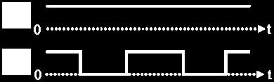
112 Operating Modes of Non-inverting Buck-Boost PFC Converter () Operating modes based on switches conditions Type S S Operating modes PWM OFF BUCK ON PWM BOOST 3 PWM PWM BUCK-BOOST Buck based equivalent converter Gate-signals for buck mode Power Conversion Lab, NCKU 9 IECON Operating Modes of Non-inverting Buck-Boost PFC Converter () Operating modes based on switches conditions Type S S Operating modes PWM OFF BUCK ON PWM BOOST 3 PWM PWM BUCK-BOOST Boost based equivalent converter Gate-signals for boost mode Power Conversion Lab, NCKU IECON

 > V o : Boost")

113 Operating Modes of Non-inverting Buck-Boost PFC Converter (3) Operating modes based on switches conditions Type S S Operating modes PWM OFF BUCK ON PWM BOOST 3 PWM PWM BUCK-BOOST Buck-Boost equivalent converter Synchronously gate-signals for buck-boost mode Power Conversion Lab, NCKU IECON Buck Boost Mode Operating modes based on switches conditions Type S S Operating modes PWM OFF BUCK ON PWM BOOST 3 PWM PWM BUCK-BOOST V in (t) > V o : Boost Mode V in (t) < V o : Buck Mode Buck Mode Boost Mode Buck Mode Buck Boost Mode Power Conversion Lab, NCKU IECON


 Distorted")


")

 i L,boost (t)")
114 Problem of BuckBoost Mode with BCM Operating modes based on switches conditions Type S S Operating modes PWM OFF BUCK 3 ON PWM PWM PWM BOOST BUCK-BOOST BCM current control Buck mode Boost mode Buck mode v in (t) V o t i L (t) Distorted inductor current between buck and boost mode in BCM. Power Conversion Lab, NCKU 3 IECON t Effect of Constant On-time t on Buck mode Boost mode Mode Transition Buck Boost i L,buck v (t) in (t) V L o t on Constant t on i L,buck (t) i L,boost (t) i L,boost (t) vin (t) t L on Power Conversion Lab, NCKU 4 IECON


115 Buck-Boost Mode with BCM Current Control Operating modes based on switches conditions Type S S Operating modes PWM OFF BUCK ON PWM BOOST BCM current control 3 PWM PWM BUCK-BOOST simulated result Buck-Boost mode avoids distorted inductor current. Power Conversion Lab, NCKU 5 IECON Normalized Input-Current i in (t) Waveforms vs. Ratio α BCM Non-inverting buck-boost PFC converter.8 better PFC performance.6 sinθ.4 α=.3 α=.5. α=.8 α= π/ π Normalized Input-Current Waveforms V V m o BCM boost PFC converter sinθ α=.3 α=.5 α=.8 α=.9 π/ π Normalized Input-Current Waveforms Power Conversion Lab, NCKU 6 IECON
116 Input Power Factor vs. Ratio α V V m o BCM Non-inverting buck-boost PFC converter BCM boost PFC converter.98.8 PF PF α PF >.96. α= α >.8 α PF deteriorated Power Conversion Lab, NCKU 7 IECON Input Power Factor in.9 to V V m o BCM Non-inverting buck-boost PFC converter BCM boost PFC converter.98 PF = PF PF PF = α α =.8 PF >.99 α =.8 PF =.95 Power Conversion Lab, NCKU 8 IECON α

 Values 7 W 9 to 64 V V dc V dc 6 Hz 55 khz Power Conversion Lab,")
 versus L V in,rms = 64V V in,rms = 9V P in = 8W V o = V")
 f sw(min) = 55 khz L =.")
117 Specifications of BCM Non-inverting Buck-Boost PFC Converter Specifications Output Power, P o Universal Input Voltage, V ac Output Voltage, V o Maximum Output Voltage Ripple, V o Source Frequency, f s Minimum Switching Frequency, f sw(min) Values 7 W 9 to 64 V V dc V dc 6 Hz 55 khz Power Conversion Lab, NCKU 9 IECON Determine Value of Main Inductor Inductor current in BCM 3 L (mh). mh Curves of f sw(min) versus L V in,rms = 64V V in,rms = 9V P in = 8W V o = V dc θ= khz f sw(min) (khz) θ=9 f sw(min) L f sw(min) P in V V in,rms in,rms V o V o θ= f sw(max) f sw(min) = 55 khz L =. mh Power Conversion Lab, NCKU IECON
118 BCM Current Control System of Proposed PFC Converter IC L656 Features: Zero Current Detector Current Comparator ZCT* for switches Constant on-time ( ZCT* : Zero-current turn-on) Power Conversion Lab, NCKU IECON Specifications & Parameters of BCM Non-inverting Buck-Boost PFC Converter Specifications Output Power, P o Input Voltage Range, V ac Output Voltage, V o Maximum Output Voltage Ripple, V o Source Frequency, f s Minimum Switching Frequency, f sw(min) Values 7 W 9 to 64 V V dc V dc 6 Hz 55 khz Parameters Inductor, L. mh Capacitor, C in μf 48 μf * Capacitor, C o Components Switches (S ; S ) Diodes (D ; D ) Values Value IRF7; IRF64 MUR44;MURD33 Power Conversion Lab, NCKU IECON
 V gs, V gs, i L (t) Time Base:")
 f sw 56 khz Time Base: ( μs/div), V gs, and V gs, : (5V/div), i L (t): (.35A/div).")
 = 9-64V rms BCM")
 = 64V rms i ac (t) Time Base: (ms/div), V o : (V/div), v ac (t): (V/div), i ac (t): (A/div) Time Base:")
119 Measured Waveforms of Inductor Current and Gate-Signals Specification: P in = 8W V ac (t) = 9V rms BCM Non-inverting buck-boost PFC converter V o = V dc Zoom-in at 9 (7 ) V gs, V gs, i L (t) Time Base: (ms/div), V gs, and V gs, : (V/div), i L (t): (.4A/div) f sw 56 khz Time Base: ( μs/div), V gs, and V gs, : (5V/div), i L (t): (.35A/div). Minimum value of switching frequency is about 56 khz Power Conversion Lab, NCKU 3 IECON Measured Waveforms of V o, V ac, and i ac of Prototype Circuit Specification: P in = 8W V ac (t) = 9-64V rms BCM Non-inverting buck-boost PFC converter V o = V dc ΔV o = V V ac (t) = 9V rms V o v ac (t) ΔV o = V V ac (t) = 64V rms i ac (t) Time Base: (ms/div), V o : (V/div), v ac (t): (V/div), i ac (t): (A/div) Time Base: (ms/div), V o : (V/div), V ac (t): (4V/div), I ac : (.5A/div) Power Conversion Lab, NCKU 4 IECON
 Measured Efficiency values are higher than.88 from V o = 5V to 5V Power Conversion Lab, NCKU 5 IECON Measured PF vs.")
120 Efficiency vs. Output Voltage with Different Input AC Voltage Specification: P in = 8W V ac (t) = 9-64V rms V o = 5-5V dc Efficiency.89 V V m o.88 V ac = 9 V rms V ac = 64 V rms Output Voltage V o (V) Measured Efficiency values are higher than.88 from V o = 5V to 5V Power Conversion Lab, NCKU 5 IECON Measured PF vs. Output Voltage with Different Input AC Voltage Specification: P in = 8W V ac (t) = 9-64V rms V o = 5-5V dc Power Factor (α=.5) (α=.3) (α=3.7) (α=.9) (α=.5) (α=.6) (α=.7) (α=.5) (α=.5) V V m o.96 (α=7.5) V ac = 9 V rms V ac = 64 V rms Output Voltage V o (V) Measured PF values are higher than.96 from α=.5 to 7.5 Power Conversion Lab, NCKU 6 IECON

 for high PF Experimental Results: PF is higher than.")
121 Measured Input-Current Harmonics with Different Input AC Voltage THD i (A) V ac (t) = 9V rms THD i (A) V ac (t) = 64V rms THD i (%) = 8% THD i (%) = 4% n Measured input-current harmonics meet IEC 6-3- Class-D Standard Power Conversion Lab, NCKU 7 IECON Non-inverting Buck-Boost Power-Factor-Correction Converter with Wide Input-Voltage-Range Applications Conclusions Proposed BCM non-inverting buck-boost converter: Reduce the voltage stresses on the components Operate in buck-boost mode to avoid distorted current Low voltage-conversion-ratio (α) for high PF Experimental Results: PF is higher than.96 Efficiency above 88% Input-current harmonics meet IEC 6-3- Class-D Standard n Power Conversion Lab, NCKU 8 IECON
122 Thanks for Your Attention! Q&A Acknowledgements This work was sponsored by the National Science Council, Taiwan, under Award Numbers NSC 97--E-6-75-MY. Also, this work made use of Shared Facilities supported by the Program of Top Universities Advancement, Ministry of Education, Taiwan. Power Conversion Lab, NCKU 9 IECON
123 AC-Side Continuous-Conduction-Mode Voltage-Source Charge-Pump Power-Factor-Correction Self-Oscillating Full-Bridge Electronic Ballasts Ray-Lee Lin and Jun-Wei Chang Speaker : Ray-Lee Lin Department of Electrical Engineering National Cheng Kung University Tainan City, Taiwan ss - Advances in Lighting Technology 3 NCKU Power Conversion Lab IECON AC-Side Continuous-Conduction-Mode Voltage-Source Charge-Pump Power- Factor-Correction Self-Oscillating Full-Bridge Electronic Ballasts. Introduction Outline. AC-side CCM VS-CP-PFC Full-Bridge Ballast 3. Steady-state Analysis 4. Design considerations 5. Implementation Results 6. Conclusions NCKU Power Conversion Lab IECON
124 DCM Charge-Pump Power-Factor-Correction Electronic Ballast D x D y C in S L EMI C B L s C dc V in C EMI Lamp C p S Drawbacks: High input current di/dt High current stress High lamp current crest-factor [4] : M. Maehara and Kadoma, High power-factor inverter device having reduced output ripple, U. S. Patent, No. 5,4,466, April 5, 995. NCKU Power Conversion Lab 3 IECON Conventional Continuous Input Current Charge-Pump Power-Factor-Correction Half-bridge Electronic Ballast L pfc D y C in S V i n L EMI C B L s C dc C EMI Lamp C p S Advantages: Low input current di/dt Low current stress Low cost Drawbacks: High crest-factor [4] : J. Qian, F. C. Lee and T. Yamauchi, A new continuous input current charge pump power factor correction electronic ballast, To be published in IEEE Industry Applications Society Annual Meeting, 997. NCKU Power Conversion Lab 4 IECON
125 Equivalent Circuit of Conventional Rectified-Side CCM Voltage-Source Charge-Pump Power-Factor-Correction Electronic Ballast L pfc D y Conventional Rectified-Side CCM VS-CP-PFC Half-bridge V in Electronic Ballast S C in V a S L s C B Lamp C p C dc V bus D x L pfc D y Equivalent circuit I in V a functions as high-frequency square-wave voltage source V in C in V a load C dc V bu s [4] : J. Qian, F. C. Lee and T. Yamauchi, A new continuous input current charge pump power factor correction electronic ballast, To be published in IEEE Industry Applications Society Annual Meeting, 997. NCKU Power Conversion Lab 5 IECON Conventional Rectified-Side CCM Voltage-Source Charge-Pump Power-Factor-Correction Electronic Ballast L pfc D y V in C in S L s C B C dc V bus Advantages: Low lamp current crest-factor Drawbacks: S Lamp C p High inrush current on S High turn-on switching loss i cin (A) 8 4 V gs (V) μsec/div Not suitable for high power applications NCKU Power Conversion Lab 6 IECON
126 Proposed Rectified-Side CCM Voltage-Source Charge-Pump Power-Factor-Correction Full-bridge Electronic Ballast (L pfc at Rectified-side) L pfc D y V in C in S L s C B C dc V bus Advantages: Low lamp current crest-factor Drawbacks: S Lamp C p High inrush current on S High turn-on switching loss V in L EMI C EMI L pfc D y D r C in D r S L x S S 3 C p L s C B Lamp S 4 C dc V bus L x is utilized to reduce range of the inrush current Advantages: Low lamp current crest-factor High power applications NCKU Power Conversion Lab 7 IECON Derivation of Proposed Rectified-side CCM Voltage-Source Charge-Pump Power-Factor-Correction Full-bridge Electronic Ballast (L pfc at AC-side) L pfc D y D y S S 3 S S 3 V in L EMI D r C in L x C p L s C B Lamp C dc V in L EMI L pfc D r C in L x L s C B C p Lamp C dc C EMI D r S S 4 C EMI D r S S 4 PFC inductor is connected from DC-side to AC-side NCKU Power Conversion Lab 8 IECON
127 Derivation of Proposed AC-Side CCM Voltage-Source Charge-Pump Power-Factor-Correction Full-bridge Electronic Ballast D y V in D r S D D L EMI L pfc C in L x L s C B S 3 C p Lamp S S 3 D r C p L EMI L pfc C in L x L s C B C dc V in Lamp C dc C EMI D r S S 4 C EMI D r S S 4 D D Diode D y can be replaced by bridge rectifier Less component count NCKU Power Conversion Lab 9 IECON Derivation of Proposed AC-Side CCM Voltage-Source Charge-Pump Power-Factor-Correction Full-bridge Electronic Ballast S S 3 S S 3 D r C p D r C p V in L EMI L pfc C in L x L s C B Lamp C dc Vin L EMI L pfc C in L x L s C B Lamp C dc C EMI D r S S 4 C EMI D r S S 4 One bridge-diode leg can be replaced by body diodes of switches Less component count NCKU Power Conversion Lab IECON
128 Duty cycle D vs. DC-bus Voltage S S 3 V ds V in L pfc D x D r C in V m L x L s C B C p Lamp C dc V bus i Lpfc,max T D x D r S S 4 i Lpfc i Lpfc,min ilpfc Δi Lpfc L v in Lpfc D T s V bus L v Lpfc in D T s D.6 DT s T s D T s D Ts V in,peak = 56V T D V V in,peak D Vbus in,peak.5.4 V bus, min D Vin, peak. when D V bus, min V in, peak V bus (V) NCKU Power Conversion Lab IECON Charge-Pump Network vs. DC-bus Voltage V in L pfc D x D r C in V m D x D r L x S S L pfc V bus V bus can be controlled by L pfc C in V bus L s C B C p S 3 Lamp S 4 C dc V bus can be controlled by C in i Lpfc, avg V bus T V T6 i T Lpfc s in D Ts 4Lpfc P V where C in (nf) in in,rms T T T3 T6 t dt ( i t dt i t dt i dt) t Lpfc Lpfc Lpfc s T Vin Vbus 4L pfc Vin D T s P B L pfc V T s T3 D Ts Vin cos(a)sin(a) Cin T in in,rms (D D ) K ω v sin(a) in L pfclx AD KVcin, t Ts ω π D Z ω Ts ω Z s Vbus v Cin in 3 B sin( A) cos( A) sin( A) sin( A) A T ω Z L L C s s pfc x in V bus =4V V bus =35V V bus =3V L pfc (mh) NCKU Power Conversion Lab IECON
129 Input current Power Factor vs. Voltage Ratio α V in PF L pfc D x D r C in V m D x D r L x S S L s C B C p S 3 Lamp S 4 V V in,peak bus C dc.5 α i Lpfc,avg V bus V ( ) V in,peak bus, min sin 4L pfc V D Ts in,peak sin V 4L V bus α in,peak α PF pfc D Ts V P Vin,peak sin DT in s Pin sin B3 Vin,rms L pfc V Vin,peak sin sin D D V V sin sin D B A bus in,peak V in V in,rms,peak bus in,peak sin (D D )sin cos(a )sin(a ) T ω Z s 3 K 3 3 sin(a 3 ) cos(a 3 ) sin(a 3) sin(a 3 ) A 3 Tsω sz 3 D T ω iin,rms Pin PF V i s ω sin π D ωs sin i ( ) d Lpfc,avg in,rms in,rms 3 NCKU Power Conversion Lab 3 IECON Input current THD i vs. Voltage Ratio α S S 3 V in L pfc D x D r C in V m L x L s C B C p Lamp C dc V bus THD i PF D x D r S S 4 THD i (%) V bus, min V in,peak V in,peak V bus 5 V bus α α PF PF THD i α NCKU Power Conversion Lab 4 IECON
130 Self-Oscillating Full-bridge Electronic Ballast S S 3 R st L L 3 C p L p L s C B C dc V in D ac Lamp D st S S 4 C st L L 4 Advantages: Simple control circuit Low cost NCKU Power Conversion Lab 5 IECON Specifications & Parameters of Proposed AC-Side CCM Voltage-Source Charge-Pump Power-Factor-Correction Self-Oscillating Full-bridge Electronic Ballast S S 3 Parameters Description D x D r R st L s L s3 C in nf L EMI L pfc C in L x L p L s C B C p C dc C dc C st μf nf V in D ac Lamp C B nf C EMI D x D r C st D st L s S L s4 S 4 C p C EMI R st 8.nF nf 56kΩ R ~R 4 Ω L pfc.9mh Specifications Values L x L s.9mh.7mh Input voltage V in AC V rms at 6Hz L EMI 4.8mH Switching frequency f s 5 khz L p,l s ~L s4 D x,d x N=4,Lm=33μH MUR46 Rated Lamp Voltage V lamp 45V D r,d r MUR46 Rated Lamp Current I lamp.555a Rated Lamp Power P lamp 8W D z ~D z8 D ac D st S ~S 4 N54 ER6 KV(A) SK3869 NCKU Power Conversion Lab 6 IECON
, v lamp (t): (5V/div), i lamp (t): (5mA/div) PF =.")
131 Measured Waveforms of V in and I in for Prototype Circuit S S 3 D x D r R st L s L s3 I in L EMI L pfc C in L x L p L s C B C p C dc V in D ac Lamp C EMI D x D r D st S S 4 C st L s L s4 V in I in Time Base: (5ms/div), v lamp (t): (5V/div), i lamp (t): (5mA/div) PF =.99 NCKU Power Conversion Lab 7 IECON Measured Waveforms of V in and I in for Prototype Circuit S S 3 D x D r R st L s L s3 I in L EMI L pfc C in L x L p L s C B C p C dc V in D ac Lamp C EMI D x D r D st S S 4 C st L s L s4 THD i (%) 35 3 IEC 6 Class-C CCM VS-CP-PFC n THD i = 8.7% Measured input-current harmonics meet IEC 6-3- Class-C Standard NCKU Power Conversion Lab 8 IECON
132 Measured Waveforms of V lamp and I lamp of Prototype Circuit S S 3 D x D r R st L s L s3 L EMI L pfc C in L x L p L s C B C p C dc V in D ac Lamp C EMI D x D r D st S S 4 C st L s L s4 I lamp V lamp Time Base: (5ms/div), v lamp (t): (35V/div), i lamp (t): (5mA/div) Zoomed in Time Base: (μs/div), v lamp (t): (35V/div), i lamp (t): (5mA/div) Lamp current crest-factor is.47 Efficiency is 88% NCKU Power Conversion Lab 9 IECON AC-Side Continuous-Conduction-Mode Voltage-Source Charge-Pump Power- Factor-Correction Self-Oscillating Full-Bridge Electronic Ballasts Conclusions AC-side CCM VS-CP-PFC self-oscillating full-bridge electronic Ballasts : Operate at CCM to reduce input current di/dt and stress Achieve high PF and low THD i Provide Low lamp current crest-factor Experimental Results: PF is.99 Efficiency is 88% Crest Factor is.47 Input-current harmonics meet IEC 6-3- Class-C Standard NCKU Power Conversion Lab IECON
133 AC-Side Continuous-Conduction-Mode Voltage-Source Charge-Pump Power- Factor-Correction Self-Oscillating Full-Bridge Electronic Ballasts Thanks for Your Attention! Q&A Acknowledgements This work was sponsored by the National Science Council, Taiwan, under Award Numbers NSC 97--E-6-75-MY. Also, this work made use of Shared Facilities supported by the Program of Top Universities Advancement, Ministry of Education, Taiwan. NCKU Power Conversion Lab IECON
134 Continuous-Conduction-Mode Charge-Pump Power-Factor-Correction Electronic Ballast with DC-Bus Voltage-Stress Reduction Function Ray-Lee Lin and Yen-Yu Chen Speaker: Ray-Lee Lin Department of Electrical Engineering National Cheng Kung University Tainan City, Taiwan. ss - Advances in Lighting Technology 3 NCKU Power Conversion Lab //8 Continuous-Conduction-Mode Charge-Pump Power-Factor-Correction Electronic Ballast with DC-Bus Voltage-Stress Reduction Function. Introduction Outline. Input notch filter for Voltage-Source (VS) Type CP-PFC electronic ballast 3. Analysis and design for Voltage-Source Type CP-PFC electronic ballast 4. Experimental results 5. Conclusions NCKU Power Conversion Lab //8
135 CCM AC-side Voltage-Source CP-PFC Electronic Ballast Advantages: Less component count High power factor CCM operation Drawback: High DC-bus voltage stress at preheat and ignition modes R. L. Lin and H. M. Shih, A Family of Piezoelectric Transformer-Based Bridgeless Continuous- Conduction-Mode Charge-Pump Power-Factor Correction Electronic Ballasts, in Proc. IEEE-IAS Annu. Meeting 4 th, 7, pp NCKU Power Conversion Lab 3 //8 Voltage Stress on DC-bus of Voltage-Source Type Ballast at Preheat Mode v DC (t) v DC (t) Steady-state: P in f s C in V Preheat mode: P AC_peak 4 V π AC_peak Low lamp power P Lamp C in, V AC_peak, V p constant f p > f s 4 π Vp VDC PLamp v DC_max v DC_rate v Lamp (t) v Lamp (t) Vp VDC PLamp in fs p Cin VAC_peak VAC_peak V DC P Lamp v Lamp - v DC - V DC Preheat preheat ignite steady state P in : input power V AC_peak :peak value of v AC V p : peak value of v Lamp P Lamp : lamp power f s : rated switching frequency f p : preheat frequency t t NCKU Power Conversion Lab 4 //8
136 Voltage Stress on DC-bus of Voltage-Source Type Ballast at Ignition Mode v DC (t) v DC (t) Steady-state: P Ignition mode: P in in fs C fs C in V AC_peak 4 V π AC_peak Low Lamp power P Lamp C in, V AC_peak, f s constant V p in V v Lamp - AC_peak 4 V π AC_peak Vp VDC PLamp V p v DC_max v DC - v Lamp (t) Vp VDC PLamp V p V DC V DC v DC_rate v Lamp (t) P Lamp preheat ignite Ignition steady state P in : input power f s : rated switching frequency V AC_peak :peak value of v AC V p : peak value of v Lamp P Lamp : lamp power t t NCKU Power Conversion Lab 5 //8 Concept to Reduce DC-bus Voltage at No-load Condition vac i in Z in D L EMI C in C b L r S C DC C EMI L pfc v DC D C f Lamp S - i in Z in At no-load condition: Z in i in V DC NCKU Power Conversion Lab 6 //8


 D C f Lamp S - NCKU")
137 Notch Filter for CCM VS CP-PFC Electronic Ballast f = f notch : High impedance gain Z notch (f) f = f s : impedance gain Only one additional notch capacitor is required f s f notch f NCKU Power Conversion Lab 7 //8 Family of Input Notch Filters for CCM VS CP-PFC Electronic Ballast (a) (b) (c) Notch Filter Type-3 i in L EMI vac C EMI L pfc L notch C notch D C in C b S L r C DC v DC (d) D C f Lamp S - NCKU Power Conversion Lab 8 //8


 C in NCKU Power")
138 Proposed Input Notch Filter for CCM VS CP-PFC Electronic Ballast Conventional: Proposed: Parallel a capacitor with L pfc NCKU Power Conversion Lab 9 //8 Relationship between DC-bus Voltage V DC and Value of C in V DC B 4 V X_avg B v AC B V Lamp B 3 P η V Lamp AC_rms V x n π sin 4 π n B B π n n π cos n Z n π B c 3 n π 3 cos π B 4 sin n 4 π n ω n ω s c ω c ω s π fs LpfcCin Z c L C pfc in (Volt) 38 C in < nf: V DC CP-PFC function cannot be achieved C in should be greater than nf V DC (nf) C in NCKU Power Conversion Lab //8
139 Relationship between Factor K and Value of C in ii in A v v AC K in i Lpfc_avg AC V x n K π Z c A π 5π A cos n 8n V π 3π A3 Zc sin n n Lamp K = A V DC π n sin n A n A 3 P η V High PF Lamp i in v AC ac_rms K(C in ) L pfc =.4mH L pfc =mh L pfc =.6mH L pfc is chosen as mh C in (nf) NCKU Power Conversion Lab //8 Relationship between Factor K and Value of L pfc ii in A v v AC K in i Lpfc_avg AC V x n K π Z c A π 5π A cos n 8n V Lamp K = π 3π A3 Zc sin n n A V DC A P η V Lamp C in > nf K closes to π n sin n A n i in v AC 3 High PF ac_rms K(L pfc ) L pfc (mh) NCKU Power Conversion Lab // C in =nf C in =3nF C in =nf
140 Design of Notch Filter for Voltage-Source Type Ballast steady-state no-load v Lamp (f) (ignite) f notch π L pfc C f pre = khz = f notch L pfc = mh notch V Lamp_rated Z notch (f) C notch =.5nF f pre = preheat frequency (steady-state) f r f s f pre (a) with C notch w/o C notch (preheat) Z notch Z Lpfc f r f s f notch (=f pre ) (b) f f NCKU Power Conversion Lab 3 //8 Specifications and Parameters for CCM VS CP-PFC Electronic Ballast D S Parameters Values v AC L EMI L pfc C EMI C in C b L r C DC L EMI C EMI 8μH 64nF D C f Lamp S L pfc C in mh nf L r 65μH Specifications Input AC voltage, V AC_rms Lamp power, P Lamp Lamp current, I Lamp Switching frequency, f s Values V rms at 6Hz 54W 46mA 6kHz C b C f S, S D, D C DC Half-bridge control IC 68nF nf STP7NB6FP PS6 47μF ST L6574 NCKU Power Conversion Lab 4 //8
 Meet IEC 6-3-")

141 Measured Waveforms of Input AC voltage v AC and Input Current i in i in PF =.975 v AC THD =5.6% v AC i in v AC i in 3% % % Class-C Standard Measured v AC : 5V/div i in : 5mA/div 5ms/div % (order) Meet IEC 6-3- Class-C Standard NCKU Power Conversion Lab 5 //8 Measured Waveforms of Input AC Voltage v AC and PFC Inductor Current i Lpfc i Lpfc D C in S v AC v AC L EMI L pfc C EMI C b L r C DC i Lpfc operates at CCM. S D C f Lamp i Lpfc v AC i Lpfc v AC v AC : 5V/div i in : 5mA/div 5ms/div NCKU Power Conversion Lab 6 //8
142 Measured Waveforms of DC-bus Voltage v DC and Lamp Current i Lamp v AC L EMI D L pfc C EMI D C f C in C b L r i Lamp Lamp S C DC S v DC - V DC_max = 3V Crest Factor =. v DC i Lamp v AC : 5V/div i in : 5mA/div 5ms/div NCKU Power Conversion Lab 7 //8 Measured Waveforms of DC-bus Voltage v DC at Preheat and Ignition Modes w/o Notch Filter: with Notch Filter: v DC v DC - - w/o Notch Filter: (a) 55V 55V 4V with Notch Filter: V ign = 7V (b) 48V 48V V pre =V steady-state preheat ignite preheat (a) v DC : V/div 5ms/div (b) V DC stress can be reduced by 7V. 8V ignite steady-state NCKU Power Conversion Lab 8 //8
143 Measured Waveforms of Input AC Voltage v AC and Input Current i in v AC i in PF =.97 THD = % i in v AC i in v AC 3% % Class-C Standard Measured v AC : 5V/div i in : 5mA/div 5ms/div % % (order) Meet IEC 6-3- Class-C Standard NCKU Power Conversion Lab 9 //8 Measured Waveforms of DC-bus voltage v DC and Lamp Current i Lamp i Lamp v DC - V DC_max = 33V Crest Factor =.9 v DC ii Lamp Lamp v AC : 5V/div i in : 5mA/div 5ms/div NCKU Power Conversion Lab //8


 DC-bus voltage can be reduced at preheat and")
144 Comparison between VS Type Ballast W/ and W/O Input Notch Filter w/o Notch Filter: with Notch Filter: D S C in v AC L EMI L pfc C EMI C b L r C DC S D C f Lamp CCM VS CP-PFC w/o Notch filter with Notch filter PF THD IEC 6-3- Class-C Standard CF Max. v DC_ign Max. v DC_SS % meet % meet NCKU Power Conversion Lab //8 Continuous-Conduction-Mode Charge-Pump Power-Factor-Correction Electronic Ballast with DC-Bus Voltage Stress Reduction Function Conclusions. Improved design guidelines for CCM VS CP-PFC electronic ballast: High PF functionality can be achieved.. Measured input current harmonics of VS type ballast satisfy IEC 6-3- Class-C Standard. 3. Proposed Input notch filter for CCM VS CP-PFC electronic ballast : (a) DC-bus voltage can be reduced at preheat and ignition modes. Preheat mode: 4V to 8V. Ignition mode: 55V to 48V. (b) Measured input current harmonics also satisfy IEC 6-3- Class-C Standard. NCKU Power Conversion Lab //8
145 Continuous-Conduction-Mode Charge-Pump Power-Factor-Correction Electronic Ballast with DC-Bus Voltage Stress Reduction Function Thanks for Your Attention! Q&A Acknowledgments This work was sponsored by the National Science Council, Taiwan, under Award Numbers NSC 97--E-6-75-MY. Also, this work made use of Shared Facilities supported by the Program of Top Universities Advancement, Ministry of Education, Taiwan. NCKU Power Conversion Lab 3 //8
146 Positive Feed-Forward Control Scheme for Distributed Buck Conversion System with Maximum Power Harvesting Function Ray-Lee Lin, Po-Yao Yeh, and *Ching-Hsiung Liu Speaker: Ray-Lee Lin Department of Electrical Engineering National Cheng Kung University Tainan City, Taiwan *Boyam Power System Co. Ltd., Tainan City, Taiwan PERE - Renewable Energy Applications Power Conversion Lab, NCKU //9 Positive Feed-Forward Control Scheme for Distributed Buck Conversion System with Maximum Power Harvesting Function Outline. Introduction of Paralleled DC-DC Power Module Systems. Proposed Positive Feed-forward Control Scheme 3. Experimental Results 4. Conclusions Power Conversion Lab, NCKU //9
147 Advantages of Paralleled DC-DC Power Module System DC-DC Power module # DC Voltage source V in DC-DC Power module # Load DC-DC Power module #N Advantages: Standardization for design N redundancy Easy for maintenance Power Conversion Lab, NCKU 3 //9 Current-Sharing Function for Paralleled DC-DC Power Module System DC-DC Power module # CS_Bus I O, DC Voltage source V in DC-DC Power module # CS_Bus I O, Load DC-DC Power module #N I O,N with current sharing bus I O, = I O, = = I O,N Lower current stress on devices Power Conversion Lab, NCKU 4 //9
148 Drawback of Single Voltage Source DC-DC Power module # CS_Bus I O, P o P source DC Voltage source V in DC-DC Power module # CS_Bus I O, Load t DC-DC Power module #N I O,N P minimum t. Output Power of DC voltage source cannot provide sufficient power for load.. Load cannot obtain required power. Power Conversion Lab, NCKU 5 //9 Paralleled DC-DC Power Module System with Multiple Individual Voltage Sources Advantages: Total power rating System reliability Power Conversion Lab, NCKU 6 //9


149 Drawback for Paralleled Power Module System with Multiple Voltage Sources Power Rating: P: w Po: W P: 3w P3: W #3 With current sharing function, every voltage source should provide 4W System is shut down because # and #3 shut down Power Conversion Lab, NCKU 7 //9 Non-ideal Voltage Sources for Paralleled Power Module System with I o Non-ideal voltage source I o r s << r s Non-ideal voltage source V in, V in V in, V in r s << r s I o I o, V in, V in I o Power Conversion Lab, NCKU 8 //9
150 PFFC Scheme for Paralleled DC-DC Power Module System DC Voltage Source # PFFC # I o, DC-DC Power module # CS_Bus DC Voltage Source # PFFC # I o, DC-DC Power module # CS_Bus Load DC Voltage Source #3 PFFC #N DC-DC Power module #N I o,n Allocating output currents of power modules Limiting input voltage level of individual power module Maximum power harvesting for power modules Power Conversion Lab, NCKU 9 //9 Principle of Positive Feed-Forward Control (PPFC) V S r S V in d Power Stage # V C I O V err V O V ref I o L O A D V in, DC level V in,high PFFC circuit V ing,low V in V CSA V C, DC level V C,High PPFC: Positive Feed-Forward Control K FF K c V C,Low V in, V C, duty cycle d V c K c V C d d V in, V C, duty cycle d V err current-loop compensator Power Conversion Lab, NCKU //9


 3 Non-ideal Voltage Source # V in (V) 3 7 7 4")
 8.")
151 Proposed Positive Feed-Forward Control Circuit Proposed PFFC Circuit I o I o voltage sensing network I o PFFC-loop compensator Power Conversion Lab, NCKU //9 V-I Curves of Employed Non-ideal Voltage Sources Non-ideal voltage source # V S r s V in I in R load I in V in Non-ideal voltage source # rs V S Specification V S V S 4V 4V Parameters r S r S mω 4 Ω Non-ideal Voltage Source # V in (V) 3 Non-ideal Voltage Source # V in (V) specified minimum voltage level I in (A) 8 5.5A I in (A) 8.5V P rating_# > P rating_# Power Conversion Lab, NCKU //9
152 Specification V S 4V 4V V S Parameters mω 4 Ω r S r S Measured Waveforms of Prototype I O =A Current Sharing Function for Power Modules Non-ideal Voltage source r S V in V S Non-ideal Voltage source V S r S V in d d Power Stage # PFFC circuit # Power Stage # I O I O I o V err I o V O V ref I o L O A D =A PFFC circuit # I o (Ch-3) I o (Ch-4) I O = A, I O = A d =.5, d =.59 d (Ch-) d (Ch-) Ch-: V/div, Ch-: V/div, Ch-3: A/div, Ch-4: V/div, Time Base= 5μ/div Power Conversion Lab, NCKU 3 //9 Specification V S 4V 4V V S Parameters mω 4 Ω r S r S Measured Waveforms of Prototype I O =5A Maximum Power Harvesting Function for Power Modules Non-ideal Voltage source r S V in V S Non-ideal Voltage source V S r S V in d d Power Stage # PFFC circuit # Power Stage # I O I O I o V err I o V O V ref I o =5A L O A D PFFC circuit # I o (Ch-3) I o (Ch-4) I O = 3.A, I O =.88A d =.5, d =.69 d (Ch-) d (Ch-) Ch-: V/div, Ch-: V/div, Ch-3: A/div, Ch-4: V/div, Time Base= 5μ/div Power Conversion Lab, NCKU 4 //9
153 Specification V S 4V 4V V S Parameters mω 4 Ω r S r S Measured Waveforms of Prototype I O =6A Maximum Power Harvesting Function for Power Modules Non-ideal Voltage source r S V in V S Non-ideal Voltage source V S r S V in d d Power Stage # PFFC circuit # Power Stage # I O I O I o V err I o V O V ref I o L O A D =6A PFFC circuit # I o (Ch-3) I o (Ch-4) I O = 4.A, I O =.88A d =.5, d =.69 d (Ch-) d (Ch-) Ch-: V/div, Ch-: V/div, Ch-3: A/div, Ch-4: V/div, Time Base= 5μ/div Power Conversion Lab, NCKU 5 //9 Specification V S V S 4V 4V Parameters r S r S mω 4 Ω Measured curves of V in, V in and V O Non-ideal Voltage source V S V S r S Non-ideal Voltage source r S V in d V in d Power Stage # PFFC circuit # Power Stage # I O I O I o V err I o V O V ref I o L O A D (V) PFFC circuit # V in V in V O I o (A) V in is clamped at 8.3V V O is regulated at V Power Conversion Lab, NCKU 6 //9
154 Measured curves of d and d Specification V S V S Parameters r S 4V 4V mω Non-ideal Voltage source V S V S r S Non-ideal Voltage source r S V in V in d d Power Stage # PFFC circuit # Power Stage # d I O I O I o V O V err V ref I o I o L O A D r S 4 Ω.7 (Duty-cycle) PFFC circuit # d d is clamped at I o (A) d Power Conversion Lab, NCKU 7 //9 Measured curves of I O and I O Specification V S V S Parameters r S 4V 4V mω Non-ideal Voltage source V S V S r S Non-ideal Voltage source r S V in V in d d Power Stage # PFFC circuit # Power Stage # I O I O I o V O V err V ref I o I o L O A D r S 4 Ω (A) PFFC circuit # current sharing I O.5.5 I O I o is limited at.88a I o (A) Power Conversion Lab, NCKU 8 //9
155 Measured curves of I in and I in Specification V S V S Parameters r S 4V 4V mω Non-ideal Voltage source V S V S r S I in Non-ideal Voltage source r S V in V in d d Power Stage # PFFC circuit # Power Stage # I O I O I o V O V err V ref I o I o L O A D r S 4 Ω PFFC circuit #.5 (A) I in.5 I in I in is limited at.3a I o (A) Power Conversion Lab, NCKU 9 // (W) Specification V S 4V 4V V S Parameters mω 4 Ω r S r S current sharing P in P in PFFC circuit # I o (A) V S Measured curves of P in and P in Non-ideal Voltage source V S r S Non-ideal Voltage source r S P in V in V in d d Power Stage # Power Stage # PFFC circuit # I O I O I o V err I o V O V ref I o L O A D P in is limited at 4W Power Conversion Lab, NCKU //9
156 Positive Feed-Forward Control Conclusions Scheme for Distributed Buck Conversion System with Maximum Power Harvesting Function Conclusions. Positive Feed-Forward Control (PPFC) scheme is proposed. Protect individual voltage source from over-current and over-power 3. Allow each individual voltage source to deliver available power 4. Apply for multi-source power conversion systems Power Conversion Lab, NCKU //9 Positive Feed-Forward Control Scheme for Distributed Buck Conversion System with Maximum Power Harvesting Function Thanks for Your Attention! Q&A Power Conversion Lab, NCKU //9
157 Design Criteria for Resonant Tank of LLC Resonant Converter Ray-Lee Lin and Chiao-Wen Lin Speaker: Ray-Lee Lin Department of Electrical Engineering National Cheng Kung University Tainan City, Taiwan PERE - Resonant Converters Power Conversion Lab, NCKU //9 Introduction Outline Design Criteria for LLC Resonant Tank Experimental Results Conclusions Design Criteria for Resonant Tank of LLC Resonant Converter Power Conversion Lab, NCKU //9
 Drawbacks:.")
158 Resonant DC-DC Converter V IN C DC-Bus V DC Resonant DC-DC V O Load - Converter - Resonant DC-DC Converters: Series resonant converter Parallel resonant converter Advantages: Low switching losses High efficiency Series-parallel resonant converter LLC resonant converter Power Conversion Lab, NCKU 3 //9 Series Resonant Converter Ideal Transformer.8 No-Load Light Load Gain SRC (db) Drawbacks:. Low output voltage gain f s /f r Cannot regulate at no-load condition Turn-on switching losses at light load condition.5.5 R. Steigerwald, A comparison of half-bridge resonant converter topologies," IEEE Trans. Power Electron., vol. 3,no., pp. 74-8, Apr Power Conversion Lab, NCKU 4 //9.6.4 ZCS Region ZVS Region
159 Parallel Resonant Converter.8.8 Low Input Voltage ZVS Region C B.6.6 PF PRC.4.4 ZCS Region High Input Voltage.. Q=.5 Q= Q= Advantages: High output voltage gain ZVS for MOSFETs f s /f r Drawbacks: Low PF of resonant tank High voltage stress on rectifiers R. Steigerwald, A comparison of half-bridge resonant converter topologies," IEEE Trans. Power Electron., vol. 3,no., pp. 74-8, Apr Power Conversion Lab, NCKU 5 //9 Series-Parallel Resonant Converter.8 PF SPRC Q=.5 Q= Q=3 ZCS Region ZVS Region High Input Voltage.. Low Input Voltage f s /f r Advantages: High output voltage gain ZVS for MOSFETs Drawbacks: Low PF of resonant tank High Voltage stress on rectifiers Bo Yang, Topology Investigation for Front End DC/DC Power Conversion for Distributed Power System, Ph.D. Dissertation, Virginia Tech, Blacksburg, VA, USA, February 3. Power Conversion Lab, NCKU 6 //9
160 Half-Bridge LLC Resonant Converter Ideal Transformer Advantages : High PF of resonant tank ZVS for MOSFETs.5.5 ZCS for rectifiers D & D Low voltage stress on rectifiers Bo Yang, Topology Investigation for Front End DC/DC Power Conversion for Distributed Power System, Ph.D. Dissertation, Virginia Tech, Blacksburg, VA, USA, February 3. Power Conversion Lab, NCKU 7 //9 Full-Bridge LLC DC-DC Resonant Converter Features: Low current stress on MOSFETs Suitable for high power application ZVS for all MOSFETS High PF of resonant tank Low voltage stress on rectifiers Bo Yang, Topology Investigation for Front End DC/DC Power Conversion for Distributed Power System, Ph.D. Dissertation, Virginia Tech, Blacksburg, VA, USA, February 3. Power Conversion Lab, NCKU 8 //9
161 Design Criteria for LLC Resonant Tank r r in m eq out - - Optimal efficiency Achieves required voltage gain High PF of resonant tank Power Conversion Lab, NCKU 9 //9 Equivalent load resistor R eq R eq i ac Equivalent load resistor R eq V O R eq v i ac ac (4 (π π) V ) (I O O n n) t 8 π n R O -V O Power Conversion Lab, NCKU //9
162 Efficiency η of LLC Resonant Tank r ESR C r L r r ESR C r L r R ω L R s eq m ω L s eq m L m R eq V out (s) (ω L ) R R s eq m s m eq (ω L ) Z in - Z in Z L Efficiency : η Re Re Z (ωs Lm) R L eq Z (ω L ) (R r ) r R in s m eq ESR ESR eq where ω s π f s Power Conversion Lab, NCKU //9 Optimal Efficiency of LLC Resonant Tank r ESR C r L r.95 L m R eq V out (s).94 Z in -.93 η Re Re Z (ωs Lm) R L eq Z (ω L ) (R r ) r R in s m eq ESR.9 ESR 3 eq ω where dη Let dr eq s π f R s eq Optimal efficiency ω η s opt L m R eq Power Conversion Lab, NCKU //9 R eq r ESR
163 Inductance Ratio k L vs. Voltage Gain C r L r 3 V in (t) - L m R eq V out (t) - Vout(s) V (s) in Inductance ratio : Gain LLC k L f n k k L L L L m r k L f k L Maximum voltage gain Power Conversion Lab, NCKU 3 //9 n f n f Minimum Inductance Ratio k L for Required Voltage Gain n f r f f s r π Lr Cr C r L r 3 k L =8 V in (t) - L m R eq V out (t) - Vout(s) V (s) in.6 k L =4 Required Volatge Gain k L = Lm Inductance ratio : k L Lr k L Maximum voltage gain Max. gain of minimum k L > Required voltage gain f n Power Conversion Lab, NCKU 4 //9
 m eq out - k - L L L m r Power factor : PF LLC V cos")

 C r L r I Lr (t) L m R")

164 Power Factor of LLC Resonant Tank r r V in (t) in I Lr (t) m eq out - k - L L L m r Power factor : PF LLC V cos I in Lr (s) (s) cosargl m fr i π fs k L f k s L f s j π f R s eq L m R eq Power Conversion Lab, NCKU 5 //9 Inductance Ratio k L vs. PF of LLC Resonant Tank V in (t) C r L r I Lr (t) L m R eq V out (t) 3 k L L L m r - - PF V cos I in Lr (s) (s) LLC dpf df LLC n k L,slop (ω r Lm ) (ω r (ω L ) m r L m ) r Lr Cr Power Conversion Lab, NCKU 6 //9
 L m R eq V out (t) PF LLC.6 k L =8 k L = - -.4.")
 (ω (ω L ) r k L,slope r m r L m ) 4 r Lr Cr k L < 4 PF")


165 Maximum Inductance Ratio k L for High PF C r L r L.8 V in (t) L m R eq V out (t) PF LLC.6 k L =8 k L = At f n = R.4 eq Lm for load matching ωr.6.8 n. (ω Lm ) (ω (ω L ) r k L,slope r m r L m ) 4 r Lr Cr k L < 4 PF LLC,fn< > PF LLC,fn> k L > 4 PF LLC,fn< < PF LLC,fn> Power Conversion Lab, NCKU 7 //9 Specifications & Parameters for Prototype Circuit Full-Bridge LLC DC-DC resonant converter with PLL control scheme 3 Q L r R eq C r.5.5 PLL: Phase-Locked Loop Power Conversion Lab, NCKU 8 //9
 Values 3V ~ 4V 48 V A khz Parameters Parallel Resonant Inductor L m Series Resonant Inductor L r Series Resonant Capacitor C r Values 46μ H 4μ H 4n F Transformer")

166 Specifications & Parameters for Prototype Circuit Full-Bridge LLC DC-DC resonant converter with PLL control scheme Specifications Input Voltage Range(V DC ) Output Voltage(V O ) Output Current (I O ) L r -C r Resonant Frequency (f r ) Values 3V ~ 4V 48 V A khz Parameters Parallel Resonant Inductor L m Series Resonant Inductor L r Series Resonant Capacitor C r Values 46μ H 4μ H 4n F Transformer Turns Ratio n p : n s :n a 9::.5 MOSFETs Q, Q, Q 3, Q 4 Diodes D and D K347 MBRFCT Power Conversion Lab, NCKU 9 //9 Waveforms of V DS,Q, V DS4,Q4, I DS,Q, and I DS4,Q4 at Full Load Condition % Load Current I O V DC I DS,Q IDS,Q4 V DS,Q - V DS,Q4 - V DC =4 V ZVS can be achieved V DC =3 V V DS,Q V DS,Q I DS,Q ZVS I DS,Q ZVS V DS,Q4 V DS,Q4 I DS,Q4 ZVS V DS,Q : 4V/div, I DS,Q : 5A/div, Time Base: 5μs/div I DS,Q4 ZVS V DS,Q : V/div, I DS,Q : 5A/div, Time Base: 5μs/div Power Conversion Lab, NCKU //9

167 Waveforms of V DS,Q, V DS4,Q4, I DS,Q, and I DS4,Q4 at 5% Load Condition 5% Load Current I O V DC IDS,Q I DS,Q4 V DS,Q - V DS,Q4 - V DC =4 V ZVS can be achieved V DC =3 V V DS,Q V DS,Q I DS,Q ZVS I DS,Q ZVS V DS,Q4 V DS,Q4 I DS,Q4 ZVS V DS,Q : 4V/div, I DS,Q : 5A/div, Time Base: 5μs/div I DS,Q4 ZVS V DS,Q : 4V/div, I DS,Q : 5A/div, Time Base: 5μs/div Power Conversion Lab, NCKU //9 Waveforms of V DS,Q, V DS4,Q4, I DS,Q, and I DS4,Q4 at % Load Condition % Load Current I O V DC IDS,Q I DS,Q4 V DS,Q - V DS,Q4 - V DC =4 V ZVS can be achieved V DC =3 V V DS,Q V DS,Q I DS,Q ZVS I DS,Q ZVS V DS,Q4 V DS,Q4 I DS,Q4 ZVS VDS,Q: 4V/div, IDS,Q: 5A/div, Time Base: 5μs/div I DS,Q4 ZVS V DS,Q : 4V/div, I DS,Q : 5A/div, Time Base: 5μs/div Power Conversion Lab, NCKU //9
國立交通大學 電子研究所 碩士論文 多電荷幫浦系統及可切換級數負電壓產生器之設計及生醫晶片應用
 國立交通大學 電子研究所 碩士論文 多電荷幫浦系統及可切換級數負電壓產生器之設計及生醫晶片應用 Design of Multiple-Charge-Pump System and Stage-Selective Negative Voltage Generator for Biomedical Applications 研究生 : 林曉平 (Shiau-Pin Lin) 指導教授 : 柯明道教授 (Prof.
MULTILAYER HIGH CURRENT/HIGH FREQUENCY FERRITE CHIP BEAD
 INTRODUCTION 產品介紹 Multilayer high current chip beads are SMD components that possess a low DC resistance. Their impedance mainly comprises resistive part. Therefore, when this component is inserted in
行政院國家科學委員會專題研究計畫成果報告
 行政院國家科學委員會專題研究計畫成果報告 W-CDMA 基地台接收系統之初始擷取與多用戶偵測子系統之研究與實作 Study and Implementation of the Acquisition and Multiuser Detection Subsystem for W-CDMA systems 計畫編號 :NSC 90-229-E-009-0 執行期限 : 90 年 月 日至 9 年 7
工程圖學 (1) Engineering Drawing (I)
 Engineering Drawing (I)") 工程圖學 (1) Engineering Drawing (I) 09510PME 101302 Instructor: Lin, Chih-Wei ( 林志偉 ) 2006/09/13 Course Information Instructor: Lin, Chih-Wei ( 林志偉 ) d937708@oz.nthu.edu.tw Office: Room 534, Engineering Building
工程圖學 (1) Engineering Drawing (I) 09510PME 101302 Instructor: Lin, Chih-Wei ( 林志偉 ) 2006/09/13 Course Information Instructor: Lin, Chih-Wei ( 林志偉 ) d937708@oz.nthu.edu.tw Office: Room 534, Engineering Building
行政院國家科學委員會補助專題研究計畫 成果報告 期中進度報告 六子棋與 K 子棋之研究
 行政院國家科學委員會補助專題研究計畫 成果報告 期中進度報告 六子棋與 K 子棋之研究 The Study of Connect6 and K-in-a-row games 計畫類別 : 個別型計畫 整合型計畫計畫編號 : NSC 95-2221-E-009-122 -MY2 執行期間 :2006 年 08 月 01 日至 2008 年 7 月 31 日 計畫主持人 : 吳毅成共同主持人 : 計畫參與人員
書報討論報告 應用雙感測觸覺感測器於手術系統 之接觸力感測
 書報討論報告 應用雙感測觸覺感測器於手術系統 之接觸力感測 報告者 : 洪瑩儒 授課老師 : 劉雲輝教授 指導老師 : 莊承鑫 盧登茂教授 Department of Mechanical Engineering & Institute of Nanotechnology, Southern Taiwan University of Science and Technology, Tainan, TAIWAN
凱思隆科技股份有限公司 公司與產品簡介. KeithLink Technology Co., Ltd. TEL: FAX:
 凱思隆科技股份有限公司 公司與產品簡介 KeithLink Technology Co., Ltd. TEL: 02-29786535 FAX: 02-29782726 service@keithlink.com 公司簡介 手動探針台 / 探針座 提供各式量測應用之探針台 / 探針座, 適用於 : 晶圓 ( 直流電性 或高頻 ) 量測 ; 液晶面板量測 ; 觸控面板 ITO 薄膜 導電高分子薄膜 矽晶片
NT-8540 / NT-8560 / NT-8580 Laser Distance Measurer
 NT-8540 / NT-8560 / NT-8580 Laser Distance Measurer User s Manual 1 st Edition, 2015 2015 Prokit s Industries Co., Ltd Overview Please carefully read this product Quick Start to ensure the safe and efficient
電機驅動方案產品介紹 廣閎科技 2016 May. 25 inergy 大比特研讨会资料区 :
 電機驅動方案產品介紹 廣閎科技 2016 May. 25 Copyright 2016 technology incorporation. All rights reserved. 廣閎科技簡介 廣閎科技是專注於節能方案應用之 IC 設計公司, 提供了由方案角度延伸的各類 IC 產品, 包含了照明 電源及電機驅動領域 廣閎科技不僅提供高品質的 IC 產品, 也協助客戶完成系統的設計及生產, 近幾年來更結合了許多上下游產業提供客戶更完整的服務
聽力內容與圖片不符, 因此選 (B) 例題 Amy: Who s that man? Mike: 答案是 (C) (A) He s a cook. (B) Yes, he s my classmate. (C) He s our coach.
 例題 Amy: Who s that man? Mike: 答案是 (C) (A) He s a cook. (B) Yes, he s my classmate. (C) He s our coach.") 新北市立江翠國民中學 103 學年度第一學期第一次定期考查七年級英語科試卷 P.1 測驗說明 : ( 一 ) 範圍 : 翰林版第一冊 Starter Unit 至 Review 1 ( 二 ) 本試卷含答案卷共 4 頁 ( 雙面印製 ) ( 三 ) 全部試題共 50 題, 第 1-35 題為單一選擇題, 請以 2B 鉛筆將正確答案的代碼劃在答案卡上, 第 36-50 題請用黑色或藍色原子筆寫在第 4
新北市立江翠國民中學 103 學年度第一學期第一次定期考查七年級英語科試卷 P.1 測驗說明 : ( 一 ) 範圍 : 翰林版第一冊 Starter Unit 至 Review 1 ( 二 ) 本試卷含答案卷共 4 頁 ( 雙面印製 ) ( 三 ) 全部試題共 50 題, 第 1-35 題為單一選擇題, 請以 2B 鉛筆將正確答案的代碼劃在答案卡上, 第 36-50 題請用黑色或藍色原子筆寫在第 4
Wireless Communications
 Wireless Communications Chapter 2 Modern Wireless Communication Systems [1] The widespread adoption of wireless communications was accelerated in the mid 1990s, when governments throughout the world provided
課程名稱 : 電子學 (2) 授課教師 : 楊武智 期 :96 學年度第 2 學期
 授課教師 : 楊武智 期 :96 學年度第 2 學期") 課程名稱 : 電子學 (2) 授課教師 : 楊武智 學 期 :96 學年度第 2 學期 1 近代 電子學電子學 主要探討課題為 微電子電路設計原理電子電路設計原理 本教材分三部份 : 基礎 設計原理及應用 基礎部份 ( 電子學 (1) 電子學 (2)): 簡介 理想運算放大器 二極体 場效應電晶体 場效應電晶体 (MOSFET) 及雙極接面電晶体 (BJT) 原理部份 ( 電子學 (3) 電子學 (4)):
課程名稱 : 電子學 (2) 授課教師 : 楊武智 學 期 :96 學年度第 2 學期 1 近代 電子學電子學 主要探討課題為 微電子電路設計原理電子電路設計原理 本教材分三部份 : 基礎 設計原理及應用 基礎部份 ( 電子學 (1) 電子學 (2)): 簡介 理想運算放大器 二極体 場效應電晶体 場效應電晶体 (MOSFET) 及雙極接面電晶体 (BJT) 原理部份 ( 電子學 (3) 電子學 (4)):
Publication Lists (2001~2005) 1. Journal Papers:
 1. Journal Papers:") Liaw, Chang-Ming ( 廖聰明 ) Professor Ph.D., National Tsing Hua University, 1988 Power Electronics, Motor Drive, Electric Machine Control E-mail: cmliaw@ee.nthu.edu.tw Fax: 886-3-5715971 Dr. Liaw was born
Liaw, Chang-Ming ( 廖聰明 ) Professor Ph.D., National Tsing Hua University, 1988 Power Electronics, Motor Drive, Electric Machine Control E-mail: cmliaw@ee.nthu.edu.tw Fax: 886-3-5715971 Dr. Liaw was born
可程式計數陣列 (PCA) 功能使用方法. 可程式計數陣列功能使用方法 Application Note 1 適用產品 :SM59D04G2,SM59D03G2
 功能使用方法. 可程式計數陣列功能使用方法 Application Note 1 適用產品 :SM59D04G2,SM59D03G2") 可程式計數陣列 (PCA) 功能使用方法 1 適用產品 :SM59D04G2,SM59D03G2 2 應用說明 : PCA 共有五組, 每組皆可工作於以下七種模式 : 捕獲模式 - 正緣捕獲模式 (Positive edge capture mode) 捕獲模式 - 負緣捕獲模式 (Negative edge capture mode) 捕獲模式 - 正緣及負緣捕獲模式 (Both positive
可程式計數陣列 (PCA) 功能使用方法 1 適用產品 :SM59D04G2,SM59D03G2 2 應用說明 : PCA 共有五組, 每組皆可工作於以下七種模式 : 捕獲模式 - 正緣捕獲模式 (Positive edge capture mode) 捕獲模式 - 負緣捕獲模式 (Negative edge capture mode) 捕獲模式 - 正緣及負緣捕獲模式 (Both positive
SECTION 機械標示 MECHANICAL IDENTIFICATION
 1 SECTION 15075 機械標示 MECHANICAL IDENTIFICATION PART 1 GENERAL 1.1 SUMMARY 摘要 A. Section includes nameplates, tags, stencils and pipe markers. 此單元包括名牌 標籤 模板 / 透板與管標識 B. Related Sections: 相關單元 1. Section
微奈米光電製程 管傑雄 國立台灣大學電機系
 微奈米光電製程 管傑雄 國立台灣大學電機系 1 Outlines 1. 基本概念 2. Optical Lithography 3. E-Beam Lithography 4. Etching Techniques 5. Applications 6. Summary 2 基本概念 (I) Scattering Length 載子傳導並遭遇散射 1. 影響散射機制 : 雜質 ( 低溫 ) 及聲子振動
計畫編號 : NSC E 執行時程 : 93 年 8 月 1 日至 94 年 7 月 31 日 計畫主持人 : 連豊力 國立台灣大學電機系助理教授 共同主持人 : 呂良鴻 國立台灣大學電子所助理教授 計畫參與人員 : 許瑋豪 方文杰 林雍倫 馮天俊 魏嘉樑 麥肇元
 微型仿生生物體之研發 (2/3) 子計畫二 : 生物群體協調行為之探討與無線通訊機制之整合 (2/3) Study of Group Behaviors of Biological Systems and Integration of Wireless Communication Protocol Design 計畫編號 : NSC 93-2213-E-002-049- 執行時程 : 93 年 8
The Electronic Design Automation (EDA) Lab
 Lab") The Electronic Design Automation (EDA) Lab 張耀文 Yao-Wen Chang ywchang@cc.ee.ntu.edu.tw http://cc.ee.ntu.edu.tw/~ywchang Graduate Institute of Electronics Engineering Department of Electrical Engineering
The Electronic Design Automation (EDA) Lab 張耀文 Yao-Wen Chang ywchang@cc.ee.ntu.edu.tw http://cc.ee.ntu.edu.tw/~ywchang Graduate Institute of Electronics Engineering Department of Electrical Engineering
Academic Year
 Academic Year 2018-19 2018 Autumn Term: Chinese Language Computing/Electronic & Computer Engineering GEN B167CF Investment Fundamentals 基礎投資知識 GEN A205CF Discovering Cultures in China 中國文化探索 GEN E142CF
#5802 使用者研究 Design and Research on User Experience
 本週課程大綱 #5802 使用者研究 Design and Research on User Experience Week 02 交大應用藝術研究所 / 工業技術研究院資通所 Dr. 莊雅量 複習 : 使用者研究的趨勢與重要性 Chap 1. Experience in Products 相關調查方法概論 Chap 2. Inquiring about Pepole s Affective Product
ORDER FORM 3A - Booth Packages Rental 訂購表格 3A - 攤位裝修設計租用
 ORDER FORM 3A - Booth Packages Rental 訂購表格 3A - 攤位裝修設計租用 Post or fax to 請郵寄或傳真往 : Tel 電話 : (852) 3605 9551/ 3605 9615 Fax 傳真 : (852) 3605 9480 Optional 隨意交回 DEADLINE : January 8, 2016 截止日期 :2016 年 1 月
FPGA-based Stepping Motor Drive System Design
 基於 FPGA 的步進馬達驅動器設計 FPGA-based Stepping Motor Drive System Design 賴秋庚廖家宏戴勝淵林宏軒蔡守亮 Chiu-Keng Lai Chia-Hung Liao Sheng-Yuan Dai Hung-Hsuan Lin Chou-Liang ai 國立勤益科技大學電機工程系 Department of Electrical Engineering
Statistical Tools for Digital Forensics. Information Technologies for IPR Protection
 Statistical Tools for Digital Forensics Information Technologies for IPR Protection Henry Chang-Yu Lee One of the world s foremost forensic scientists. Chief Emeritus for Scientific Services for the State
Journal of Commercial Modernization, 6(2), 作者 /Author: 張瑞當 (Ruey-Dang Chang); 曾玉琦 (Yee-Chy Tseng); 廖浩雲 (Hao-Yun Liao)
, 作者 /Author: 張瑞當 (Ruey-Dang Chang); 曾玉琦 (Yee-Chy Tseng); 廖浩雲 (Hao-Yun Liao)") 集團企業資訊透明度與盈餘管理 Information Transparency of the Affiliated Business Groups and Earnings Management doi:0.632/jcm.20.6.2.0 商業現代化學刊, 6(2), 20 Journal of Commercial Modernization, 6(2), 20 作者 /Author: 張瑞當
集團企業資訊透明度與盈餘管理 Information Transparency of the Affiliated Business Groups and Earnings Management doi:0.632/jcm.20.6.2.0 商業現代化學刊, 6(2), 20 Journal of Commercial Modernization, 6(2), 20 作者 /Author: 張瑞當
Multimeter 3 1/2經濟款數位電錶 MT User s Manual 2nd Edition, Copyright by Prokit s Industries Co., Ltd.
 MT-1210 Multimeter 3 1/2經濟款數位電錶 User s Manual 2nd Edition, 2017 2017 Copyright by Prokit s Industries Co., Ltd. SAFETY INFORMATION This multimeter has been designed according to IEC 1010 concerning electronic
24GHz BSD Radar. 24 GHz Radar Blind Spot Detection. Installation Guide
 P/N : VS-91A001 Page :1 of 8 24 GHz Radar Blind Spot Detection Installation Guide P/N : VS-91A001 Page :2 of 8 CONTENT 1. SYSTEM ARCHITECTURE TURE 1.1 Layout... 3 1.2 Components.....4 2. Installation 2.1
Virtual Reality 虛擬實境
 Virtual Reality 0. Course Introduction NCU IPVR Lab. 1 Virtual Reality 虛擬實境 Prof. Din-Chang Tseng Dept. of CSIE, National Central Univ. 曾定章教授中央大學資訊工程系 E-mail: tsengdc@ip.csie.ncu.edu.tw Feb. ~ Jun. 2019
一個可以創造奇蹟的行業 儒鴻企業股份有限公司 成衣事業部陳總經理坤鎕
 一個可以創造奇蹟的行業 儒鴻企業股份有限公司 成衣事業部陳總經理坤鎕 1 1 Comfortable Life Enterprise Ever-Lasting COMFORTABLE LASTING ELASTIC & EVERGREEN E.C.L.A.T ADVANCED Advanced Technology Fabrics & Garments TECHNOLOGY Constantly Technical
樊晉源簡歷 元智大學 / 工業工程與管理研究所 / 博士 (2005/06/30~2009/06/30) 大葉大學 / 事業經營研究所 / 碩士 (2001/06/30~2003/06/30) 科技政策研究與資訊中心政策研究組副研究員 (2014/01/01~ 迄今 )
 大葉大學 / 事業經營研究所 / 碩士 (2001/06/30~2003/06/30) 科技政策研究與資訊中心政策研究組副研究員 (2014/01/01~ 迄今 )") 樊晉源簡歷 一 基本資料 : 姓名 : 樊晉源 E-MAIL:cyfan@stpi.narl.org.tw 二 教育背景 : 元智大學 / 工業工程與管理研究所 / 博士 (2005/06/30~2009/06/30) 大葉大學 / 事業經營研究所 / 碩士 (2001/06/30~2003/06/30) 三 現職 : 科技政策研究與資訊中心政策研究組副研究員 (2014/01/01 迄今 ) 四
樊晉源簡歷 一 基本資料 : 姓名 : 樊晉源 E-MAIL:cyfan@stpi.narl.org.tw 二 教育背景 : 元智大學 / 工業工程與管理研究所 / 博士 (2005/06/30~2009/06/30) 大葉大學 / 事業經營研究所 / 碩士 (2001/06/30~2003/06/30) 三 現職 : 科技政策研究與資訊中心政策研究組副研究員 (2014/01/01 迄今 ) 四
Unit 6: Movies. Film Genre ( 可加 film 或 movie) Adjectives. Vocabulary. animation. action. drama. comedy. crime. romance. horror
 Adjectives. Vocabulary. animation. action. drama. comedy. crime. romance. horror") Unit 6: Movies Vocabulary Film Genre ( 可加 film 或 movie) action comedy romance horror thriller adventure animation drama crime science fiction (sci-fi) musical war Adjectives exciting fascinating terrifying
Unit 6: Movies Vocabulary Film Genre ( 可加 film 或 movie) action comedy romance horror thriller adventure animation drama crime science fiction (sci-fi) musical war Adjectives exciting fascinating terrifying
國立交通大學 工業工程與管理學系 博士論文 利用電腦輔助設計資料防止錯打線的視覺偵測系統之設計與開發
 國立交通大學 工業工程與管理學系 博士論文 利用電腦輔助設計資料防止錯打線的視覺偵測系統之設計與開發 A CAD-based Vision Approach for Incorrect Wire Bonding Prevention System Design and Development 研究生:李恕明 指導教授:彭德保博士 中華民國九十八年七月 利用電腦輔助設計資料防止錯打線的視覺偵測系統之設計
國立交通大學 資訊科學與工程研究所碩士論文 多天線傳送系統干擾抑制及路徑衰減補償之可適性封包檢測. Adaptive Packet Acquisition with Interference and Time-Variant Path Loss in MIMO-OFDM Systems
 國立交通大學 資訊科學與工程研究所碩士論文 多天線傳送系統干擾抑制及路徑衰減補償之可適性封包檢測 Adaptive Packet Acquisition with Interference and Time-Variant Path Loss in MIMO-OFDM Systems 研究生 : 呂理聖 指導教授 : 許騰尹教授 中華民國九十五年七月 多天線傳送系統干擾抑制及路徑衰減補償之可適性封包檢測
震波醫療機之設計與開發 Design and Development of Shock Wave Therapy
 震波醫療機之設計與開發 Design and Development of Shock Wave Therapy 梁勝明遠東科技大學電腦應用工程系教授 馬亞尼義守大學生物醫學工程學系副教授 1 萬龍瑞 國立成功大學航空太空學系研究生 摘 要 本研究設計與開發了一套具電子式高壓放電系統之電水式體外震波醫療機以提供在震波碎石術 骨疾治療 消脂及其他醫療技術所需之震波產生源 本文所設計與開發之震波醫療機是由五個子系統所組成,
30 個創意思考技巧. Checklists Brainstorming Forced Relationships/Analogy Attribute Listing Morphological Analysis Imitation Mindmapping
 創意思考技巧 533 30 個創意思考技巧 Random Input Problem Reversal Ask Questions Applied Imagination - Question Summary Lateral Thinking Six Thinking Hats The Discontinuity Principle 534 30 個創意思考技巧 Checklists Brainstorming
Power Challenges for IoT devices
 Power Challenges for IoT devices Wireless signaling test/ DC Power consumption Solution Architect/ Keysight General Electronic Measurement Soluiton R&D Brian Chi 祁子年 Agenda IOT Signaling Test Solution
GENERAL RULES & REGULATIONS FOR THE 23 rd DA DUN FINE ARTS EXHIBITION OF TAICHUNG CITY
 GENERAL RULES & REGULATIONS FOR THE 23 rd DA DUN FINE ARTS EXHIBITION OF TAICHUNG CITY 1. Purpose: To enhance international cultural exchanges and raise standards for artistic creation. 2. Organizers:
行政院國家科學委員會補助 大專學生參與專題研究計畫研究成果報告
 行政院國家科學委員會補助 大專學生參與專題研究計畫研究成果報告 ************************************* * 計畫 * * : 以腦波控制外骨骼機器人之研究 * * 名稱 An EEG-based Approach for Exoskeleton Control * ************************************* 執行計畫學生 : 謝宗翰學生計畫編號
OEM Installation Guidance Document For BRCM WLAN + Bluetooth Module, BCM94313HMGB FCC ID: QDS-BRCM1051; IC: 4324A-BRCM1051
 Conditions on using BRCM regulatory approvals: A. Customer must ensure that its product (the CUSTOMER Product ) is electrically identical to Broadcom s reference designs. Customer acknowledges that any
國立交通大學 電信工程學系 碩士論文 連續時間轉導電容式三角積分調變器之實現. Implementation of the continuous-time transconductor-capacitor Delta-Sigma modulator 研究生 : 吳國璽 指導教授 : 洪崇智博士
 國立交通大學 電信工程學系 碩士論文 連續時間轉導電容式三角積分調變器之實現 Implementation of the continuous-time transconductor-capacitor Delta-Sigma modulator 研究生 : 吳國璽 指導教授 : 洪崇智博士 中華民國九十六年十月 連續時間轉導電容式三角積分調變器之實現 Implementation of the continuous-time
國家同步輻射研究中心出國報告書 出國人姓名 : 王端正 出國日期 :105 年 4 月 25 日至 29 日 目的地 ( 國家 城市 ): 中國, 蘇州
: 中國, 蘇州") 國家同步輻射研究中心出國報告書 出國人姓名 : 王端正 出國日期 :105 年 4 月 25 日至 29 日 目的地 ( 國家 城市 ): 中國, 蘇州 參加會議名稱或考察 研究訓練地點 : 2016 先進光學製造與檢測技術研討會 The 8 th SPIE international Symposium on advanced optical manufacturing and testing technology
國家同步輻射研究中心出國報告書 出國人姓名 : 王端正 出國日期 :105 年 4 月 25 日至 29 日 目的地 ( 國家 城市 ): 中國, 蘇州 參加會議名稱或考察 研究訓練地點 : 2016 先進光學製造與檢測技術研討會 The 8 th SPIE international Symposium on advanced optical manufacturing and testing technology
國立交通大學 經營管理研究所 碩士論文 上游獨占下之外部授權者的最適授權策略. The Optimal Licensing Strategy of an Outsider Patentee under. the Single Upstream Supplier 研究生 : 林錦宏
 國立交通大學 經營管理研究所 碩士論文 上游獨占下之外部授權者的最適授權策略 The Optimal Licensing Strategy of an Outsider Patentee under the Single Upstream Supplier 研究生 : 林錦宏 指導教授 : 胡均立教授 中華民國九十八年五月 上游獨占下之外部授權者的最適授權策略 The Optimal Licensing
User s Manual. Wi-Fi Smart Plug HS100 Wi-Fi Smart Plug with Energy Monitoring HS REV 2.0.0
 Wi-Fi Smart Plug HS100 Wi-Fi Smart Plug with Energy Monitoring HS110 1910012024 REV 2.0.0 Copyright & Trademarks Specifications are subject to change without notice. TP-Link is a registered trademark of
5G Technology Development in ITRI
 5G Technology Development in ITRI Pang-An Ting Division for Emerging Wireless Application Technology ICL/ITRI 2017/01/22 Copyright 2017 ITRI 工業技術研究院 Our Views on 5G R&D Copyright 2017 ITRI 工業技術研究院 3 Our
User Manual bgn WLAN MODULE MODEL DWM-W042
 User Manual 802.11bgn WLAN MODULE MODEL DWM-W042 The purpose of this manual is to explain correct way how to integrate module DWM-W042 to the end product. It includes procedures that shall assist you to
允許學生個人 非營利性的圖書館或公立學校合理使用本基金會網站所提供之各項試題及其解答 可直接下載而不須申請. 重版 系統地複製或大量重製這些資料的任何部分, 必須獲得財團法人臺北市九章數學教育基金會的授權許可 申請此項授權請電郵
 注意 : 允許學生個人 非營利性的圖書館或公立學校合理使用本基金會網站所提供之各項試題及其解答 可直接下載而不須申請 重版 系統地複製或大量重製這些資料的任何部分, 必須獲得財團法人臺北市九章數學教育基金會的授權許可 申請此項授權請電郵 ccmp@seed.net.tw Notice: Individual students, nonprofit libraries, or schools are
Using the Keyboard (VGP-WKB11)
") n 32 (VGP-WKB11) A wireless keyboard is supplied with your computer. The wireless keyboard uses a standard key arrangement with additional keys that perform specific functions. Using the Wireless Keyboard
n 32 (VGP-WKB11) A wireless keyboard is supplied with your computer. The wireless keyboard uses a standard key arrangement with additional keys that perform specific functions. Using the Wireless Keyboard
Design of an Op-Amp Gain Compensator for Switched-Capacitor Integrators
 國立交通大學 電機與控制工程學系 碩士論文 交換電容式積分器 之運算放大器增益補償的設計 Design of an Op-mp Gain Compensator for Switched-Capacitor Integrators 研究生 : 許皓淵指導教授 : 鄭木火博士 中華民國九十七年七月 交換電容式積分器 之運算放大器增益補償的設計 Design of an Op-mp Gain Compensator
to possess 2. Description of type or types of irradiating apparatus for which licence is required : dental X-ray machine
 RADIATION ORDINANCE (Chapter 303) APPLICATION FOR IRRADIATING APPARATUS LICENCE I ABC Company Limited (Name of full) of Information (Address in full) hereby make application for a licence (a) to possess
HONG KONG SAR, CHINA
 HONG KONG SAR, CHINA Richard Kirke MANAGING DIRECTOR HONG KONG Richard.Kirke@colliers.com DIR +852 2822 0699 FAX +852 2107 6001 Richard Kirke joined in 2009 as Managing Director of the Hong Kong office.
測試報告 TestReport 號碼 (No.) : CE/2017/B1020 日期 (Date) : 2017/11/13 明輝化工實業有限公司 MIN FEI CHEMICALS INDUSTRIES CO., LTD. 新北市土城區大安路 138 巷 32 號 NO. 32, LANE 13
 : CE/2017/B1020 日期 (Date) : 2017/11/13 明輝化工實業有限公司 MIN FEI CHEMICALS INDUSTRIES CO., LTD. 新北市土城區大安路 138 巷 32 號 NO. 32, LANE 13") 頁數 (Page) 1 of 5 以下測試樣品係由申請廠商所提供及確認 (The following sample(s) was/were submitted and identified by/on behalf of the applicant as) 送樣廠商 (Sample Submitted By) 樣品名稱 (Sample Description) 樣品型號 (Style/Item No.)
頁數 (Page) 1 of 5 以下測試樣品係由申請廠商所提供及確認 (The following sample(s) was/were submitted and identified by/on behalf of the applicant as) 送樣廠商 (Sample Submitted By) 樣品名稱 (Sample Description) 樣品型號 (Style/Item No.)
海象觀測同調性都卜勒微波雷達的開發 林昭暉 國立中央大學水文與海洋科學研究所助理教授 2 國立中央大學水文與海洋科學研究所博士班研究生 2 國立中央大學水文與海洋科學研究所研究助理 國家實驗研究院台灣海洋科技研究中心助理研究員
 第 35 屆海洋工程研討會論文集國立中山大學 2013 年 11 月 Proceedings of the 35 th Ocean Engineering Conference in Taiwan National Sun Yat-sen University, November 2013 海象觀測同調性都卜勒微波雷達的開發 錢樺 1 鄭皓元 2 林昭暉 3 賴堅戊 1 國立中央大學水文與海洋科學研究所助理教授
BOARD OF DIRECTORS AND COMMITTEES 董事局及委員會
 BOARD OF DIRECTORS AND COMMITTEES 04 Hong Kong Internet Registration Corporation Limited 2017 Annual Report Hong Kong Internet Registration Corporation Limited ( HKIRC ) is a non-profit-distributing, non-statutory,
Search Smarter: How AI can change your Research 李箐 IEEE 中國區資訊經理
 Search Smarter: How AI can change your Research 李箐 IEEE 中國區資訊經理 Agenda The power of AI: search smarter; research smarter Deciphering the mystery of AI via IEEE Xplore Enjoy the beauty of AI via InnovationQ
DC-DC 轉換器的基本觀念與定義 2008 年 1 月 8 日. Lab808: 電力電子系統與晶片實驗室 台灣新竹 交通大學 電機與控制工程研究所. Power Electronic Systems & Chips, NCTU, TAIWAN
 台灣新竹 交通大學 電機與控制工程研究所 808 實驗室電力電子系統晶片 數位電源 DSP 控制 馬達與伺服控制 Lab-808: Power Electronic Systems & Chips Lab., NCTU, Taiwan http://pemclab.cn.nctu.edu.tw/ DC-DC 轉換器的基本觀念與定義 鄒應嶼 教授 國立交通大學 電機與控制工程研究所 2008 年 1
允許學生個人 非營利性的圖書館或公立學校合理使用本基金會網站所提供之各項試題及其解答 可直接下載而不須申請. 重版 系統地複製或大量重製這些資料的任何部分, 必須獲得財團法人臺北市九章數學教育基金會的授權許可 申請此項授權請電郵
 注意 : 允許學生個人 非營利性的圖書館或公立學校合理使用本基金會網站所提供之各項試題及其解答 可直接下載而不須申請 重版 系統地複製或大量重製這些資料的任何部分, 必須獲得財團法人臺北市九章數學教育基金會的授權許可 申請此項授權請電郵 ccmp@seed.net.tw Notice: Individual students, nonprofit libraries, or schools are
國立交通大學 電子工程學系電子研究所 碩士論文. An Effective Heart Rate Variability Processor Design for. Portable 3-Lead ECG Monitoring System-on-Chip 研究生 : 曾少彥
 國立交通大學 電子工程學系電子研究所 碩士論文 適用於可攜式三通道 ECG 遠端照護系統晶片之有 效的心跳變異率處理器設計 An Effective Heart Rate Variability Processor Design for Portable 3-Lead ECG Monitoring System-on-Chip 研究生 : 曾少彥 指導教授 : 方偉騏教授 中華民國九十九年十二月 適用於可攜式三通道
允許學生個人 非營利性的圖書館或公立學校合理使用本基金會網站所提供之各項試題及其解答 可直接下載而不須申請. 重版 系統地複製或大量重製這些資料的任何部分, 必須獲得財團法人臺北市九章數學教育基金會的授權許可 申請此項授權請電郵
 注意 : 允許學生個人 非營利性的圖書館或公立學校合理使用本基金會網站所提供之各項試題及其解答 可直接下載而不須申請 重版 系統地複製或大量重製這些資料的任何部分, 必須獲得財團法人臺北市九章數學教育基金會的授權許可 申請此項授權請電郵 ccmp@seed.net.tw Notice: Individual students, nonprofit libraries, or schools are
Big Data and High Performance Computing
 Big Data and High Performance Computing Big data and high performance computing focus on academic research and technology development in areas of high performance computing platform architecture, parallel
Class-AB Rail-to-Rail CMOS Buffer Amplifier for TFT-LCD Source Drivers 應用於薄膜電晶體液晶顯示器資料驅動電路的 AB 類軌對軌互補式金屬氧化物半導體場效電晶體緩衝放大器
 興大工程學刊第二十一卷第三期 ( 二 一 年十一月 ) Journal of Engineering, National Chung Hsing University, Vol. 21, No. 3, pp. 1-12 (2010) 1 Class-AB Rail-to-Rail CMOS Buffer Amplifier for TFT-LCD Source Drivers Yen-Ting Chen
射頻微波通訊電路設計 RF/Microwave Communication Circuits Design
 射頻微波通訊電路設計 RF/Microwave Communication Circuits Design Huey-Ru Chuang CCE/EE NCKU 莊惠如成功大學電通所 / 電機工程系 2014 Interference signals Desired Channel c Interference signals BPF response Desired Channel c LNA SHM
STS & 社會學 課程介紹 課程大綱. 定稿 (6/Feb. 2015) 陽明大學 STS 所傅大為 ex: 7902 星期四 10am-1pm
 陽明大學 STS 所傅大為 ex: 7902 星期四 10am-1pm") STS & 社會學 定稿 (6/Feb. 2015) 陽明大學 STS 所傅大為 ex: 7902 dwfu@ym.edu.tw 星期四 10am-1pm 課程介紹 一些學界人士或研究生會有個看法, 多少有點望文生義, 說科技與社會研究 (STS), 是個社會學領域中的新興學門, 是個社會學中的次學門 但真的是如此嗎? 雖然有不少社會學家積極參與 STS, 但 STS 裡的研究者也包括了醫學史家 科學史家
STS & 社會學 定稿 (6/Feb. 2015) 陽明大學 STS 所傅大為 ex: 7902 dwfu@ym.edu.tw 星期四 10am-1pm 課程介紹 一些學界人士或研究生會有個看法, 多少有點望文生義, 說科技與社會研究 (STS), 是個社會學領域中的新興學門, 是個社會學中的次學門 但真的是如此嗎? 雖然有不少社會學家積極參與 STS, 但 STS 裡的研究者也包括了醫學史家 科學史家
天線工程. Antenna Engineering (1) 莊惠如 成功大學電機系/電通所 EE NCKU CCE/EE NCKU. Huey-Ru Chuang 95年度(下) r r.
 莊惠如 成功大學電機系/電通所 EE NCKU CCE/EE NCKU. Huey-Ru Chuang 95年度(下) r r.") 天線工程 Antenna Engineering (1) 2007 CCE/ Huey-Ru Chuang 莊惠如 成功大學電機系/電通所 r r 1 E (r ) = 4π r N + r ρ V [ jωµjψ J m ψ + ε ψ]dv 1 4π i =1 Si r r r [ jωµ(nˆ H )ψ + (nˆ E ) ψ + (nˆ E ) ψ]ds 95年度(下) 2007 天線工程
天線工程 Antenna Engineering (1) 2007 CCE/ Huey-Ru Chuang 莊惠如 成功大學電機系/電通所 r r 1 E (r ) = 4π r N + r ρ V [ jωµjψ J m ψ + ε ψ]dv 1 4π i =1 Si r r r [ jωµ(nˆ H )ψ + (nˆ E ) ψ + (nˆ E ) ψ]ds 95年度(下) 2007 天線工程
高速數位電路與無線通訊系統之電磁相容技術發展與應用
 高速數位電路與無線通訊系統之電磁相容技術發展與應用 林漢年 / 主任 逢甲大學通訊工程系 /IC-EMC 研究發展中心 1 2016 ANSYS, Inc. August 31, 2016 ANSYS UGM 2016 2 Outline Introduction to EMI and RFI for High-Speed Systems Trend of Wireless Communications
2018 TAIROS 國際論壇 TAIROS International Forum 2018
 2018 TAIROS 國際論壇 TAIROS International Forum 2018 TAIROS 國際論壇邀集美國 MICROSOFT IOT & AI Solutions UL 澳門大學科技學院 國立中央大學電機系 美國約翰霍布金斯大學等多位國際機器人與人工智慧專家齊聚一堂, 深度剖析產業趨勢和技術動態, 預計將吸引國內外產業專業人士參與, 連同 TAIROS 2018 展覽精彩引爆!
DBUB-P705 Bluetooth Adapter User s Manual
 DBUB-P705 Bluetooth Adapter User s Manual This document provides safety instructions and describes the specifications. Read this document carefully before installing to ensure your safety and product performance.
國立交通大學 電信工程研究所 博士論文 新穎交錯耦合濾波器之開發設計與寬頻高階馬迅平衡非平衡轉換器合成設計
 國立交通大學 電信工程研究所 博士論文 新穎交錯耦合濾波器之開發設計與寬頻高階馬迅平衡非平衡轉換器合成設計 Development and Design of Novel Cross-Coupled Filters and Exact Synthesis of New High-Order Wideband Marchand Balun 研究生 : 呂哲慶 指導教授 : 張志揚 (Jhe-Ching
Bluetooth Module : MB8811C1 SPECIFICATION. Tx Power Rx Sensitivity < -70dBm (BER 0.1%)
") Bluetooth Module : MB8811C1 [top] [bottom] This MB8811C1 Module is compatible with Bluetooth specification version 4.0. MB8811C1 is a fully integrated RF, baseband controller etc. SPECIFICATION Main Chips
Bluetooth Module : MB8811C1 [top] [bottom] This MB8811C1 Module is compatible with Bluetooth specification version 4.0. MB8811C1 is a fully integrated RF, baseband controller etc. SPECIFICATION Main Chips
PART III: BOOTH CONSTRUCTION FORMS 第三部分..攤位裝修表格
 PART III: BOOTH CONSTRUCTION FORMS 第三部分..攤位裝修表格 FORM 表格 DESCRIPTION 表格名稱 SUBMISSION 表格遞交 DEADLINE 遞交期限 RETURN TO 交回 2.1 Raw Space Exhibitors Declaration 展覽空地參展商申報 Compulsory for Raw Space Exhibitors 空地參展商必須交回
VISUAL ARTS ADVANCED LEVEL. 1.1 To examine candidates general creative ability.
 VISUAL ARTS ADVANCED LEVEL AIMS AND OBJECTIVES 1.1 To examine candidates general creative ability. 1.2 To examine candidates visual literacy and handling of media, materials, and techniques as applied
SPECIFICATION FOR APPROVAL
 SPECIFICATION FOR APPROVAL CUSTOMER: DESCRIPTION: MODEL NO: PART NO: DESIGNED NO: 170408-0613 JUL.31th.2017 DATE: CUSTOMER APPROVED SIGNATURES VENDOR APPROVED SIGNATURES 經理 課長 繪圖員 田青松 歐陽建瓊 羅珍珍 CUSTOMER
第壹部分 : 選擇題 (60 分 ) 一 綜合測驗 ( 第 1-15 題, 每題 2 分, 共 30 分 )
 一 綜合測驗 ( 第 1-15 題, 每題 2 分, 共 30 分 )") 第壹部分 : 選擇題 (60 分 ) 一 綜合測驗 ( 第 1-15 題, 每題 2 分, 共 30 分 ) 說明 : 下列三篇短文共有 15 個空格, 請依短文文意, 選出一個最適合該空格的答案, 並將代號標示在答案卡上 1-5 題為題組 There is majesty about the sea, which covers over 70 percent of the Earth s surface.
第壹部分 : 選擇題 (60 分 ) 一 綜合測驗 ( 第 1-15 題, 每題 2 分, 共 30 分 ) 說明 : 下列三篇短文共有 15 個空格, 請依短文文意, 選出一個最適合該空格的答案, 並將代號標示在答案卡上 1-5 題為題組 There is majesty about the sea, which covers over 70 percent of the Earth s surface.
允許學生個人 非營利性的圖書館或公立學校合理使用本基金會網站所提供之各項試題及其解答 可直接下載而不須申請. 重版 系統地複製或大量重製這些資料的任何部分, 必須獲得財團法人臺北市九章數學教育基金會的授權許可 申請此項授權請電郵
 注意 : 允許學生個人 非營利性的圖書館或公立學校合理使用本基金會網站所提供之各項試題及其解答 可直接下載而不須申請 重版 系統地複製或大量重製這些資料的任何部分, 必須獲得財團法人臺北市九章數學教育基金會的授權許可 申請此項授權請電郵 ccmp@seed.net.tw Notice: Individual students, nonprofit libraries, or schools are
VISUAL ARTS ADVANCED LEVEL. 1.1 To examine candidates general creative ability.
 Revised as at November 2010 AIMS AND OBJECTIVES VISUAL ARTS ADVANCED LEVEL 1.1 To examine candidates general creative ability. 1.2 To examine candidates visual literacy and handling of media, materials,
Rev. No. History Issue Date Remark 0.1 Initial issue Mar 24, 2008 Preliminary
 Document Title Data Sheet (Chinese Version) Revision History Rev. No. History Issue Date Remark 0.1 Initial issue Mar 24, 2008 Preliminary Important Notice: AMICCOM reserves the right to make changes to
Land Use Change Detection Using Satellite Imagery
 Land Use Change Detection Using Satellite Imagery Chi-Farn Chen Center for Space and Remote Sensing Research National Central University TAIWAN Tel : 886-3-4227151-57624 Fax : 886-3-4254908 e-mail : cfchen@csrsr.ncu.edu.tw
Model RM Wireless Link Module External Interface Specification
 Model 420128RM Wireless Link Module External Interface Specification 2016/6/13 Introduction Model 420128RM Wireless Link Module is for the low latency wireless link between console and bass box or rear
Milton Group Newsletter Season 1, 2015
 1 Milton Group Project Management Workshop 2015 2 We are Celebrating 25th Anniversary 2015 3 Milton Granted The 4th outstanding SME Social Responsibility Award 2015 by The Mirror Post 4 Milton builds a
機械工程研究所博士聯絡電話 : (03) International Crisis Management Association. 2003,2005 Training Organization 2003, 2005, 2007,2009.
 International Crisis Management Association. 2003,2005 Training Organization 2003, 2005, 2007,2009.") 姓名 : 陳文欽學歷 : 美國佛羅里達大學 (University of Florida) 機械工程研究所博士聯絡電話 : (03) 518-6585 傳真 : (03) 518-6575 E - mail:wenchin@chu.edu.tw 類別 : 專任師資職稱 : 教授兼推廣教育處處長研究專長 : 製程參數最佳化系統 先進製程控制與類神經應用 自動化監控系統 績效評估 國內外之成就與榮譽 International
姓名 : 陳文欽學歷 : 美國佛羅里達大學 (University of Florida) 機械工程研究所博士聯絡電話 : (03) 518-6585 傳真 : (03) 518-6575 E - mail:wenchin@chu.edu.tw 類別 : 專任師資職稱 : 教授兼推廣教育處處長研究專長 : 製程參數最佳化系統 先進製程控制與類神經應用 自動化監控系統 績效評估 國內外之成就與榮譽 International
Large Signal Behavior of Micro-speakers. by Wolfgang Klippel, KLIPPEL GmbH ISEAT 2013
 Large Signal Behavior of Micro-speakers by Wolfgang Klippel, KLIPPEL GmbH Institute of Acoustics and Speech Communication Dresden University of Technology ISEAT 2013 Klippel, Modeling of Micro-speakers,
Signal Integrity for PCB Design
 Signal Integrity for PCB Design Sep 17, 2014 Lin, Ming Chih Agenda Customizable in Footer Page 2 What does PCB matters for Signal Integrity? Impedance, Loss and Delay of Transmission Line TDR, TDT and
igs01 Specification BLE( Bluetooth Smart) to WiFi Gateway Features Applications Block Diagram Specification Ver.1b
 to WiFi Gateway Features Applications Block Diagram Specification Ver.1b") Specification Ver.1b igs01 Specification BLE( Bluetooth Smart) to WiFi Gateway igs01 is a BLE to WiFi gateway and bridge. The gateway reads ibeacon and Eddystone like beacon or customized Tag( w/ sensor)
Specification Ver.1b igs01 Specification BLE( Bluetooth Smart) to WiFi Gateway igs01 is a BLE to WiFi gateway and bridge. The gateway reads ibeacon and Eddystone like beacon or customized Tag( w/ sensor)
MARQUE : REFERENCE : CODIC :
 MARQUE : REFERENCE : CODIC : TP-LINK HS 110 4378695 NOTICE Wi-Fi Smart Plug HS100 Wi-Fi Smart Plug with Energy Monitoring HS110 1910012261 REV 2.0.1 Copyright & Trademarks Specifications are subject to
Leading Provider of Industrial Networking Solutions
 Leading Provider of Industrial Networking Solutions Moxa at a Glance Moxa was founded in 1987, and is now a leading supplier of device networking products and solutions for industry. Moxa has networked
允許學生個人 非營利性的圖書館或公立學校合理使用本基金會網站所提供之各項試題及其解答 可直接下載而不須申請. 重版 系統地複製或大量重製這些資料的任何部分, 必須獲得財團法人臺北市九章數學教育基金會的授權許可 申請此項授權請電郵
 注意 : 允許學生個人 非營利性的圖書館或公立學校合理使用本基金會網站所提供之各項試題及其解答 可直接下載而不須申請 重版 系統地複製或大量重製這些資料的任何部分, 必須獲得財團法人臺北市九章數學教育基金會的授權許可 申請此項授權請電郵 ccmp@seed.net.tw Notice: Individual students, nonprofit libraries, or schools are
CANNONWAY CONSTRUCTION CONSULTANTS (MACAU ) CO. LTD. Cannonway 建築諮詢顧問 ( 澳門 ) 有限公司
 CO. LTD. Cannonway 建築諮詢顧問 ( 澳門 ) 有限公司") Presents A HALF DAY SEMINAR The Effect of the Economic Tsunami on Construction and Investment in Macau 主辨金融海嘯下如何影響澳門的建設界與投資 **Revised Date To be held on 11 th December 2008 Revised Date** From 2:00 to
Presents A HALF DAY SEMINAR The Effect of the Economic Tsunami on Construction and Investment in Macau 主辨金融海嘯下如何影響澳門的建設界與投資 **Revised Date To be held on 11 th December 2008 Revised Date** From 2:00 to
3GPP 標準推廣說明會 Spectrum Sharing Aspects in 3GPP
 3GPP 標準推廣說明會 Spectrum Sharing Aspects in 3GPP 簡均哲 資訊工業策進會 智慧網通所 / 先進通訊中心 1 3 Usage Scenarios and 8 Key Capabilities in ITU-R Vision 2 Spectrum requirement in 2020 Source: ITU-R Report M.2290, The full
BIOGRAPHICAL DETAILS OF DIRECTORS, COMPANY SECRETARY AND CHIEF FINANCIAL OFFICER
 BIOGRAPHICAL DETAILS OF DIRECTORS, EXECUTIVE DIRECTORS Mr. Lin Fan, aged 50, is the chairman and an executive director of the Company. Mr. Lin was appointed as the vice president of CIHC and CIHK in July
Design of A Fast Lock-in All-Digital Phase-Locked Loop in 40-nm CMOS Technology
 國立中正大學 資訊工程研究所碩士論文 40 奈米製程下開發與設計快速鎖定之 全數位鎖相迴路 Design of A Fast Lock-in All-Digital Phase-Locked Loop in 40-nm CMOS Technology 研究生 : 指導教授 : 羅啟光 鍾菁哲博士 中華民國一零四年七月 - I - - I - - II - - III - 摘要 近年來, 系統晶片 (SoC)
1995 年間, 彼擔任香港期貨交易所主席,1989 至 2000 年同時為香港期貨交易所及香港期貨結算有限公司董事 彼曾任香港證券及期貨事務監察委員會諮詢委員會成員, 及股東權益小組成員 梁肩負培育金融專才的使命 彼曾任香港
 LEONG Ka-Chai 梁家齊 OBE SBS JP 銀紫荊星章太平紳士 Leong Ka-Chai has over 30 years experience in the securities and derivatives industry. He has been the Chairman of Roctec group of companies since 1983. He is committed
歷年具審稿之學術論文 (Refereed Papers)(* Corresponding author)
(* Corresponding author)") 歷年具審稿之學術論文 (Refereed Papers)(* Corresponding author) 1. 呂世通 *(2000), 公共工程變更設計原因之統計分析 - 以台北市公共工程為例, 審計季刊, 第二十一卷, 第一期, pp. 49-66 2. 謝定亞 呂世通 * 陳正鈞 (2001), 台北市公共工程完工驗收延遲原因分析及其改善途徑, 審計季刊, 第二十二卷, 第一期, pp.27-43
歷年具審稿之學術論文 (Refereed Papers)(* Corresponding author) 1. 呂世通 *(2000), 公共工程變更設計原因之統計分析 - 以台北市公共工程為例, 審計季刊, 第二十一卷, 第一期, pp. 49-66 2. 謝定亞 呂世通 * 陳正鈞 (2001), 台北市公共工程完工驗收延遲原因分析及其改善途徑, 審計季刊, 第二十二卷, 第一期, pp.27-43
Goodsky Technical Data. Contact Details
 Goodsky Technical Data The following page(s) are extracted from multi-page Goodsky product catalogues or CDROMs and any page number shown is relevant to the original document. The PDF sheets here may have
允許學生個人 非營利性的圖書館或公立學校合理使用本基金會網站所提供之各項試題及其解答 可直接下載而不須申請. 重版 系統地複製或大量重製這些資料的任何部分, 必須獲得財團法人臺北市九章數學教育基金會的授權許可 申請此項授權請電郵
 注意 : 允許學生個人 非營利性的圖書館或公立學校合理使用本基金會網站所提供之各項試題及其解答 可直接下載而不須申請 重版 系統地複製或大量重製這些資料的任何部分, 必須獲得財團法人臺北市九章數學教育基金會的授權許可 申請此項授權請電郵 ccmp@seed.net.tw Notice: Individual students, nonprofit libraries, or schools are
Visible Light Communications
 Mobile and Vehicular Network Lab Visible Light Communications Hsin- Mu (Michael) Tsai ( 蔡欣穆 ) Computer Science and Information Engineering National Taiwan University 前瞻資訊科技 2013/3/29 Borrowing the slides
6. Material Description and RoHS Test Report / Page 9 ~ end
 Specification For Approval Date: 2014 / 03 / 13 File No.: 140313004 Version: 1.0 Customer: XW Customer P/N: / INVAX P/N: SMA312-CGT5PB-D Description : Coaxial Connector Cortec Checked By: Customer Approved
BA 商品多樣化 商品多樣性的介紹 可以和感應器和指示燈等各種元件連接的端子台模組 有 點型 ( 輸入 ) 點型 ( 輸入 輸出 ) 0 點型 ( 輸入 輸出 ) 等種類 可以不經由繼電器轉接而可以和空氣閥和電磁閥等直接連接的 00mA 開關型式 配備可簡單進行動作確認的 LED 指示燈 DIN 軌
 點型 ( 輸入 輸出 ) 0 點型 ( 輸入 輸出 ) 等種類 可以不經由繼電器轉接而可以和空氣閥和電磁閥等直接連接的 00mA 開關型式 配備可簡單進行動作確認的 LED 指示燈 DIN 軌") e.enproteko.com BA 型連接端子系列 用一對纜線傳送多數個信號的省配線 模組備有多樣化系列產品 依各類需求 可自由自在做應用組合 益 成 h 自 H ttp ://s 動控 ale 制.en 材 pro 料 tek 行 o.c om 特 長 一對纜線連接 輸入 / 輸出機器最遠可達 00m B A 型 連 接 端 子 系 列 Q 使用前 配線作業及維修之效率化 防止配線錯誤 削減成本
e.enproteko.com BA 型連接端子系列 用一對纜線傳送多數個信號的省配線 模組備有多樣化系列產品 依各類需求 可自由自在做應用組合 益 成 h 自 H ttp ://s 動控 ale 制.en 材 pro 料 tek 行 o.c om 特 長 一對纜線連接 輸入 / 輸出機器最遠可達 00m B A 型 連 接 端 子 系 列 Q 使用前 配線作業及維修之效率化 防止配線錯誤 削減成本
EAST ASIA THIRD-SECTOR RESEARCHERS NETWORK NEWSLETTER NEWS 最新消息
 EAST ASIA THIRD-SECTOR RESEARCHERS NETWORK NEWSLETTER 東亞第三部門研究人員網絡通信 Issue 5 / February, 2018 CONTENTS 目錄 News 最新消息 Introduction 簡介 Publications 學術出版 VOLUNTAS. Volume 28, Issue 6, December 2017. Conference
teachers guide
 HONG KONG SCIENCE MUSEUM. SPECIAL EXHIBITION 15.06-17.10.2018 teachers guide Presented by Jointly organised by 簡介 超越天空 專題展覽由波音贊助, 展示在航空航天發展歷程上前所未見的互動體驗, 介紹人類首次動力飛行, 以至在地球上和太空中的最新創科成果 展覽採用了模擬飛行器 互動體驗劇場
WML- 43 User Manual. Content. 1. General. Page 1 of 6 WML-C43_User_Manual Jun
 Page 1 of 6 WML- 43 User Manual The purpose of this manual is to explain correct way how to integrate module WML- 43 to the end product. It includes procedures that shall assist you to avoid unforeseen