高速數位電路與無線通訊系統之電磁相容技術發展與應用
|
|
|
- Christopher Ryan
- 5 years ago
- Views:
Transcription
1 高速數位電路與無線通訊系統之電磁相容技術發展與應用 林漢年 / 主任 逢甲大學通訊工程系 /IC-EMC 研究發展中心 ANSYS, Inc. August 31, 2016 ANSYS UGM 2016
2 2 Outline Introduction to EMI and RFI for High-Speed Systems Trend of Wireless Communications and Automotive Development Platform Noise Impact on Throughput EMI Analysis of Key Components in Mobile Device Application of Noise Budget and Analysis Model for System Integration Conclusion ANSYS, Inc. August 31, 2016 ANSYS UGM 2016

 3 2016")
3 What is EMI and EMC? Natural Sources: Lightning, Electrostatic Discharge (ESD) - Artificial Noise: EFT dv/dt di/dt EMI 干擾源 信號源 耦合路徑 信號接收器 ( 敏感設備 ) ANSYS, Inc. August 31, 2016 ANSYS UGM 2016


4 EMI vs. RF Interference Calculations: ANSYS, Inc. August 31, 2016 ANSYS UGM 2016


5 High Speed Digital System Trends More complex designs, more power on chip, and more susceptible Most powerful EM sources RF MCU DSP Memory Bus control ADC DAC Test Most susceptible parts ANSYS, Inc. August 31, 2016 ANSYS UGM 2016


6 ANSYS, Inc. August 31, 2016 ANSYS UGM 2016 Problems by Power/Ground Noise

7 Challenges in High Speed Digital Design ANSYS, Inc. August 31, 2016 ANSYS UGM 2016
8 Triangle of EMC related Issues EMC Normal Mode Radiation Common Mode Radiation Interference SI (Signal Integrity) Delay/Timing Control Reflection Noise Crosstalk Noise Eye Opening Jitter 8 PI (Power Integrity) PWR/GND Plane Resonance SSN PWR Supply Impedance Decoupling ANSYS, Inc. August 31, 2016 ANSYS UGM 2016
9 9 Outline Introduction to EMI and RFI for High-Speed Systems Trend of Wireless Communications and Automotive Development Platform Noise Impact on Throughput EMI Analysis of Key Components in Mobile Device Application of Noise Budget and Analysis Model for System Integration Conclusion ANSYS, Inc. August 31, 2016 ANSYS UGM 2016

10 10 The mobile communication and trend toward higher data bandwidth ANSYS, Inc. August 31, 2016 ANSYS UGM 2016

 higher speed connectivity (2Mbps) high speed Broadband (>20Mbps)")
11 11 Evolution of Wireless Devices RF SAR OTA TP? Applications Innovation IP-LBS-HD Resolution,. 1G 2G 2.5G 3G 4G-5G analog voice communication digital services quicker data access (384kbps) higher speed connectivity (2Mbps) high speed Broadband (>20Mbps) ANSYS, Inc. August 31, 2016 ANSYS UGM 2016


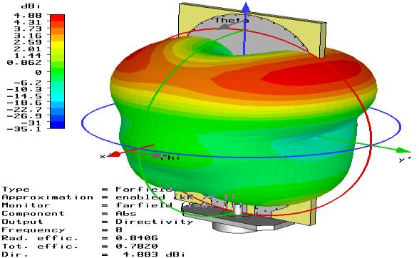
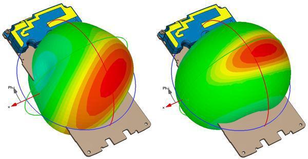
12 Antenna Near Field and Far Field ANSYS, Inc. August 31, 2016 ANSYS UGM 2016


13 What s the OTA Measurement? OTA: Over-the-Air The purpose is to measure the 3-dimensions (X, Y, Z) antenna pattern for transmit power and receiver sensitivity for wireless devices. (Regulation) (CTIA) ANSYS, Inc. August 31, 2016 ANSYS UGM

14 What is On-Board Self Jamming? LTE Lots of on-board antennas/wireless modules in Modern Mobile Phone!! ANSYS, Inc. August 31, 2016 ANSYS UGM 2016


15 車輛 EMC 環境 EV 充電環境 Amateur Radio Aviation Radar Broadcasting Tower 傳統道路環境 Cellular phone Protection of receiver ANSYS, Inc. August 31, 2016 ANSYS UGM 2016

16 Advanced Driver Assistance Systems (ADAS) ANSYS, Inc. August 31, 2016 ANSYS UGM 2016

17 Complex Automobiles Electronic 當車輛使用電源線與 AC 電力網路連線進行充電時, 則須符合 AC 電網 EMC 相關規範 使用範圍多廣, 須依政府法令規定 使用範圍多深, 視車廠品質確保程度而定 ANSYS, Inc. August 31, 2016 ANSYS UGM 2016
18 18 Outline Introduction to EMI and RFI for High-Speed Systems Trend of Wireless Communications and Automotive Development Platform Noise Impact on Throughput EMI Analysis of Key Components in Mobile Device Application of Noise Budget and Analysis Model for System Integration Conclusion ANSYS, Inc. August 31, 2016 ANSYS UGM 2016


19 19 Figure of Merit for MIMO Systems - Throughput De-Sense represented by Noise PDF at different channel ANSYS, Inc. August 31, 2016 ANSYS UGM 2016
 is used to emulate multi-path Unless otherwise requested, channels used by default (Ch. 11 20MHz or Ch.")
20 Hybrid: OTA + Conduction Full Anechoic RF Chamber with fixed multi-path & in-line programmable attenuation between the AP & DUT to simulate changing RF conditions NOTE: A phase shifter (Butler matrix) is used to emulate multi-path Unless otherwise requested, channels used by default (Ch MHz or Ch MHz) Traffic type used by default (TCP) iperf commands: Sender: iperf c <IP_OF_SERVER> -w 256K l 1470 P4 fm i1 t<duration> Receiver: iperf s w 256K ANSYS, Inc. August 31, 2016 ANSYS UGM 2016


")


21 Setup for Throughput Measurement (Server) (AP) (DUT ) Conduction Test Setup OTA Test Setup ANSYS, Inc. August 31, 2016 ANSYS UGM 2016
22 22 Throughput(Mbps) AP2 & AP3 - CH 01 (Tx mode) CH01 TX Total Attenuation (db) AP2 AP3 AP2-AP n TX (20MHz) AP2 AP Total Attenuation(dB) ANSYS, Inc. August 31, 2016 ANSYS UGM 2016
23 23 Throughput(Mbps) AP2 & AP3 - CH 01 (Rx mode) CH01 RX Total Attenuation (db) AP2 AP3 AP2-AP n RX (20MHz) AP2 AP Total Attenuation(dB) ANSYS, Inc. August 31, 2016 ANSYS UGM 2016
24 24 Throughput(Mbps) AP2 & AP3 - CH 06 (Tx mode) CH06 TX Total Attenuation (db) AP2 AP3 AP2-AP n TX (20MHz) AP2 AP Total Attenuation(dB) ANSYS, Inc. August 31, 2016 ANSYS UGM 2016
25 25 Throughput(Mbps) AP2 & AP3 - CH 06 (Rx mode) CH06 RX Total Attenuation (db) AP2 AP3 AP2-AP n RX (20MHz) AP2 AP Total Attenuation(dB) ANSYS, Inc. August 31, 2016 ANSYS UGM 2016
26 26 Throughput(Mbps) AP2 & AP3 - CH 11 (Tx mode) CH11 TX Total Attenuation (db) AP2 AP3 AP2-AP n TX (20MHz) AP2 AP Total Attenuation(dB) ANSYS, Inc. August 31, 2016 ANSYS UGM 2016
27 Throughput(Mbps) AP2 & AP3 - CH 11 (Rx mode) CH11 RX Total Attenuation (db) AP2 AP3 AP2-AP n RX (20MHz) AP2 AP Total Attenuation(dB) ANSYS, Inc. August 31, 2016 ANSYS UGM 2016
28 28 Mbps Mpbs 13.3 Notebook: CH01(1/3) (AP-2) 實測衰減 110deg (Ant 130cm) CH01 CH01 86db 86db Tx Rx 衰減器 A 衰減器 C Average (AP-3) 實測衰減 110deg (Ant 130cm) CH01 CH01 86db 86db Tx Rx 衰減器 A 衰減器 C Average CH01 Tx degree Tx-Ap2 CH01 Rx Tx-Ap degree Rx-Ap2 Rx-Ap ANSYS, Inc. August 31, 2016 ANSYS UGM 2016
29 29 Mbps Mbps 13.3 Notebook: CH06(2/3) (AP-2) 實測衰減 110deg (Ant 130cm) CH06 CH06 86db 86db Tx Rx 衰減器 A 衰減器 C Average (AP-3) 實測衰減 110deg (Ant 130cm) CH06 CH06 86db 86db Tx Rx 衰減器 A 衰減器 C Average CH06 Tx Tx-Ap2 degree CH06 Rx Tx-Ap degree Rx-Ap2 Rx-Ap ANSYS, Inc. August 31, 2016 ANSYS UGM 2016
30 30 Mbps Mbps 13.3 Notebook: CH11(3/3) (AP-2) 實測衰減 110deg (Ant 130cm) CH11 CH11 86db 86db Tx Rx 衰減器 A 衰減器 C Average (AP-3) 實測衰減 110deg (Ant 130cm) CH11 CH11 86db 86db Tx Rx 衰減器 A 衰減器 C Average CH11 Tx Tx-Ap2 degree CH11 Rx Tx-Ap degree Rx-Ap2 Rx-Ap ANSYS, Inc. August 31, 2016 ANSYS UGM 2016
31 31 Mbps Mbps 15 Notebook: CH01(1/3) (AP-2) 實測衰減 110deg (Ant 105cm) CH01 CH01 86db 86db Tx Rx 衰減器 A 衰減器 C Average (AP-3) 實測衰減 110deg (Ant 105cm) CH01 CH01 86db 86db Tx Rx 衰減器 A 衰減器 C Average CH01 Tx Tx-Ap2 degree CH01 Rx Tx-Ap degree Rx-Ap2 Rx-Ap ANSYS, Inc. August 31, 2016 ANSYS UGM 2016
32 32 Mbps Mbps 15 Notebook: CH06(2/3) (AP-2) 實測衰減 110deg (Ant 105cm) CH06 CH06 86db 86db Tx Rx 實測衰減 110deg (Ant 105cm) CH06 衰減器 A CH06 86db 86db Tx Rx 衰減器 C 衰減器 A 衰減器 C Average (AP-3) Average CH06 Tx degree Tx-Ap2 Tx-Ap3 Ch06 Rx degree Rx-Ap2 Rx-Ap ANSYS, Inc. August 31, 2016 ANSYS UGM 2016
33 33 Mbps Mbps 15 Notebook: CH11(3/3) (AP-2) 實測衰減 110deg (Ant 105cm) CH11 CH11 86db 86db Tx Rx 衰減器 A 衰減器 C (AP-3) 實測衰減 110deg (Ant 105cm) CH11 CH11 86db 86db Tx Rx 衰減器 A 衰減器 C CH11 Tx degree Tx-Ap2 Tx-Ap CH11 Rx Average Average degree Rx-Ap2 Rx-Ap ANSYS, Inc. August 31, 2016 ANSYS UGM 2016


34 34 Setup for Antenna Port Noise inside view Complete set up view Back view ANSYS, Inc. August 31, 2016 ANSYS UGM 2016
 35 2016 ANSYS, Inc.")
35 35 dbm Platform Noise (WLAN_Main) Platform_noise Background Platform noise Main WLAN_Main_LF15V Frequency(GHz) ANSYS, Inc. August 31, 2016 ANSYS UGM 2016
 36 2016 ANSYS, Inc.")
36 36 dbm Platform Noise(WLAN_AUX) Platform_noise Background Platform noise AUX WLAN_AUX_LF15V Frequency(GHz) ANSYS, Inc. August 31, 2016 ANSYS UGM 2016


37 37 Surface Scan to Locate Noise Source Front view Complete setup view ANSYS, Inc. August 31, 2016 ANSYS UGM 2016

38 38 Current RFI Mitigation Practices ANSYS, Inc. August 31, 2016 ANSYS UGM 2016
39 39 屏蔽材料對於雜訊抑制效果比較 未加材料 _Probe 0 加入材料 ( 石墨烯 )_Probe ANSYS, Inc. August 31, 2016 ANSYS UGM 2016
40 40 屏蔽材料對於雜訊抑制效果比較 未加材料 _Probe 90 加入材料 ( 石墨烯 )_Probe ANSYS, Inc. August 31, 2016 ANSYS UGM 2016
41 41 屏蔽材料對於雜訊抑制效果比較 未加材料 _Probe 0 加入材料 ( 石墨烯 )_Probe ANSYS, Inc. August 31, 2016 ANSYS UGM 2016
42 42 屏蔽材料對於雜訊抑制效果比較 未加材料 _Probe 90 加入材料 ( 石墨烯 )_Probe ANSYS, Inc. August 31, 2016 ANSYS UGM 2016


43 43 Throughput 量測 量測場地示意圖 實際量測場地 DUT Antenna AP Controller ANSYS, Inc. August 31, 2016 ANSYS UGM 2016
44 44 Throughput (Uplink) ANSYS, Inc. August 31, 2016 ANSYS UGM 2016
45 45 Throughput (Downlink) ANSYS, Inc. August 31, 2016 ANSYS UGM 2016
46 46 Throughput (Bidirectional) ANSYS, Inc. August 31, 2016 ANSYS UGM 2016
47 47 Outline Introduction to EMI and RFI for High-Speed Systems Trend of Wireless Communications and Automotive Development Platform Noise Impact on Throughput EMI Analysis of Key Components in Mobile Device Application of Noise Budget and Analysis Model for System Integration Conclusion ANSYS, Inc. August 31, 2016 ANSYS UGM 2016
48 Internal EMI Sources Fields Conduction E & H Fields on Structure Parasitic effects Capacitive Coupling SI, Crosstalk Inductive Coupling Layout and placement PCB, Chassis, Connectors, External Cables Radiated Coupling (CM, DM) Aperture/Resonant effects SPD Shielding Power distribution Signal distribution Ground loop Conductive Coupling Filtering Induced Current & Charge on Structure or victim components ANSYS, Inc. August 31, 2016 ANSYS UGM 2016
49 49 Estimating RF Interference Levels in Mixed Digital/RF Designs ANSYS, Inc. August 31, 2016 ANSYS UGM 2016

50 RFI/EMI Analysis for RF Devices Near Field Far Field Possible coupling paths Radiation through aperture in chassis and picked up by antenna. Direct field coupling inside chassis, heat-sink radiation, high speed signal trace radiation, etc. Coupling through power distribution system. Coupling through loop formed by chassis and ground planes ANSYS, Inc. August 31, 2016 ANSYS UGM 2016


51 ANSYS, Inc. August 31, 2016 ANSYS UGM 2016 Near field Coupling Path Loss

52 Platform Noise is a problem today and will get worse if we do nothing Platform RF Interference severely impacts wireless performance. Getting worse for future platforms More Victim Radios Licensed Radios (more stringent reqs.) Higher GHz Sources (I/O & Components) UMD devices force noise closer to radios ANSYS, Inc. August 31, 2016 ANSYS UGM 2016
53 53 The difference between wireless link rate, actual file transfer and web browsing speed RF S/N Performance TIS (Sensitivity) Platform Noise Coupling (Physical Layer) Data Rate Throughput quality of experience (QoE) High Speed Digital (ICs/Modules) User Scenario (Application Layer) Webpage Loading ANSYS, Inc. August 31, 2016 ANSYS UGM 2016


54 ANSYS, Inc. August 31, 2016 ANSYS UGM 2016 Aspect of EMC stages

55 Critical industrial needs for EMC ANSYS, Inc. August 31, 2016 ANSYS UGM

56 Development trends for new EMC-strategies product ANSYS, Inc. August 31, 2016 ANSYS UGM 2016
57 Key Components for Wireless Devices ANSYS, Inc. August 31, 2016 ANSYS UGM 2016
58 Link budget vs. Noise budget Link Budget - Specify all the component - Specification like insertion loss, VSWR, NF, from antenna to I/Q demodulator. ANTENNA GAIN DIPLEXER INSERTION LOSS MISMATCHING LOSS LNA GAIN LNA NOISE FIGURE SAW FILTER LOSS MIXER CONVERSTION LOSS SAW FILTER LOSS I/Q CONVERSTION LOSS 58 Noise Budget - Specify the Noise power Specification for different component at different location Noise Power CPU NORTH BRIDGE(LVDS DIRVER.) MEMORY LVDS SOKET LVDS FLAT FLEX CABLE LCD PANEL (T-CON, BACKLIGHT) WEB CAM MINI COAXIAL CABLE FOR RF SOUTH BRIDGE ANSYS, Inc. August 31, 2016 ANSYS UGM 2016
59 59 Outline Introduction to EMI and RFI for High-Speed Systems Trend of Wireless Communications and Automotive Development Platform Noise Impact on Throughput EMI Analysis of Key Components in Mobile Device Application of Noise Budget and Analysis Model for System Integration Conclusion ANSYS, Inc. August 31, 2016 ANSYS UGM 2016


60 Equipment designers want to predict EMC before fabrication Siemens Automotive Toulouse Most of the time, EMC measurements are performed once the equipment is built. No improvements can be done at conception phase. Predict EMC performances IC, board, equipment optimizations However, need of non-confidential IC models (black box models) ANSYS, Inc. August 31, 2016 ANSYS UGM 2016


61 61 Application Concept of Noise Budget Interference Source Interference Frequencies Interference Position Communications Performance ANSYS, Inc. August 31, 2016 ANSYS UGM 2016


62 Predict system-level performance from component-level information Old Approach: Put the components in a typical system and measurement the system performance. Better Approach: Fully characterize the components themselves, then model system behavior ANSYS, Inc. August 31, 2016 ANSYS UGM 2016
63 Compatibility Analysis Model Magnetic Probe TEM Cell BCI. N Limit (dbm) = ESD Waveform EFT Waveform EMI Spectrum S M (dbm) + G A (dbi) SNR (db) Generic Standards Basic Standards Product Family Standards Product Standards ANSYS, Inc. August 31, 2016 ANSYS UGM 2016
64 Mechanisms for ICEM parasitic emission Couple through supply lines (PI) Direct Radiated coupling Couple through input/output lines (SI) Component measurements should characterize the source in order to build models that can be used at the system level. Otherwise, they are mostly useless! ANSYS, Inc. August 31, 2016 ANSYS UGM 2016

65 65 Standard methods for emission characterization of ICs ANSYS, Inc. August 31, 2016 ANSYS UGM 2016

66 66 Standard methods for immunity characterization of ICs ANSYS, Inc. August 31, 2016 ANSYS UGM 2016

67 Intra-System EMI and PCB level EMC System level EMC must be taken care at component level ANSYS, Inc. August 31, 2016 ANSYS UGM 2016
68 Pre-Layout Placement Design Major players in this interference problem Digital IC Noise Source a library model RF Interference Coupling Path modeling or measurement RF antenna Victim a library model Noise voltage at RF receiver can be quickly estimated ANSYS, Inc. August 31, 2016 ANSYS UGM 2016


69 Two Source Reconstruction Approaches Source reconstruction based on TEM cell measurement - Test PCB - Dipole extraction from TEM measurement - Correlation to far-field measurement Source reconstruction based on near-field scanning measurement - Calculation of equivalent dipole array from near-field scanning - Reconstruction of fields at any location from dipole array ANSYS, Inc. August 31, 2016 ANSYS UGM 2016
 Vertical scan plot from a full 3D near-field")
 70 2016 ANSYS, Inc.")
70 70 Horizontal and vertical magnetic near field scan of a SoC (a) 2D horizontal scan (b) Vertical scan plot from a full 3D near-field scan (Nexio from 2016 IEEE Electromagnetic Compatibility Magazine Volume 5 Quarter 1) ANSYS, Inc. August 31, 2016 ANSYS UGM 2016

71 Hierarchy Measurement and Modeling for EMC IEC IEC IEC IEC ESA 模組 : ISO RF/Antenna 模組整車 : ISO CISPR 12/25 ECE R10 Wireless: 3GPP; CTIA 環境電磁場 ANSYS, Inc. August 31, 2016 ANSYS UGM 2016

72 ANSYS, Inc. August 31, 2016 ANSYS UGM 2016
73 73 Outline Introduction to EMI and RFI for High-Speed Systems Trend of Wireless Communications and Automotive Development Platform Noise Impact on Throughput EMI Analysis of Key Components in Mobile Device Application of Noise Budget and Analysis Model for System Integration Conclusion ANSYS, Inc. August 31, 2016 ANSYS UGM 2016
74 EMC Design Strategies 1. 頻譜控制 (Spectrum Management) 干擾源 4. 接地設計 (grounding) 5. 佈線設計 (Layout Design) Radiated Field 3. 屏蔽材料 (shielding) Conducted 2. 濾波元件 (Filter) TVS/filter 受害者 ( 敏感設備 ) ANSYS, Inc. August 31, 2016 ANSYS UGM 2016
75 75 Emerging Platform Trends Ultra-mobile, ultra-compact and consumer platforms will drive pervasive changes in chip-level RFI & EMI just as they are doing to chip power and packaging. More radios and RF coexistence Pocket-sized form factors Increasing data rates & performance requirements Usage driven performance criteria Pressure to eliminate shields & reduce size will be intense. SiP s don t allow for board-level fixes. Silicon must be right. No time for multiple design spins ANSYS, Inc. August 31, 2016 ANSYS UGM 2016
76 EMC Challenge and Development for Future From Inter-System Regulations Requirement Regulatory Design: SAR HAC RF RSE AGPS (Debugging with Antenna Design RF Absorber shielding and filtering) Full Automobiles Through Intra-System Coupling Analysis OTA Performance Requirement for Wireless Communications (Edge of Link) MIMO (Throughput) Automobile Modules To Silicon Chip and Package Level Request Noise budget for IC EMC measurement IC EMI Noise Modeling S/N Prediction (Placement Coupling) ANSYS, Inc. August 31, 2016 ANSYS UGM 2016


77 Isotropic Radiator Concept for Noisy IC Placement ANSYS, Inc. August 31, 2016 ANSYS UGM 2016

78 Before Components EMC Adoption Conductive tapes everywhere ANSYS, Inc. August 31, 2016 ANSYS UGM 2016


79 After Components EMC Adoption Solutions are on component side ANSYS, Inc. August 31, 2016 ANSYS UGM 2016


80 感谢聆听 ANSYS, Inc. August 31, 2016 ANSYS UGM 2016
MULTILAYER HIGH CURRENT/HIGH FREQUENCY FERRITE CHIP BEAD
 INTRODUCTION 產品介紹 Multilayer high current chip beads are SMD components that possess a low DC resistance. Their impedance mainly comprises resistive part. Therefore, when this component is inserted in
Todd Hubing. Clemson University. Cabin Environment Communication System. Controls Airbag Entertainment Systems Deployment
 Automotive Component Measurements for Determining Vehicle-Level Radiated Emissions Todd Hubing Michelin Professor of Vehicular Electronics Clemson University Automobiles are Complex Electronic Systems
Electromagnetic Compatibility
 Electromagnetic Compatibility Introduction to EMC International Standards Measurement Setups Emissions Applications for Switch-Mode Power Supplies Filters 1 What is EMC? A system is electromagnetic compatible
Comparison of IC Conducted Emission Measurement Methods
 IEEE TRANSACTIONS ON INSTRUMENTATION AND MEASUREMENT, VOL. 52, NO. 3, JUNE 2003 839 Comparison of IC Conducted Emission Measurement Methods Franco Fiori, Member, IEEE, and Francesco Musolino, Member, IEEE
24GHz BSD Radar. 24 GHz Radar Blind Spot Detection. Installation Guide
 P/N : VS-91A001 Page :1 of 8 24 GHz Radar Blind Spot Detection Installation Guide P/N : VS-91A001 Page :2 of 8 CONTENT 1. SYSTEM ARCHITECTURE TURE 1.1 Layout... 3 1.2 Components.....4 2. Installation 2.1
Product Description. Theory of operation
 TC-5062C 6 GHz TEM Cell Product TC-5062C, 6 GHz TEM Cell generates the Electro-Magnetic field for testing small RF devices such as wireless communication receiver, Mobile phone, etc An external test signal
EMI and its Implications in Multi-Radio Integration. Harry Skinner Principal Engineer Corporate Technology Group Intel Corporation
 EMI and its Implications in Multi-Radio Integration Harry Skinner Principal Engineer Corporate Technology Group Intel Corporation November 15 th 2007 Agenda Background Problem Statement EMI / Platform
Overview of EMC Regulations and Testing. Prof. Tzong-Lin Wu Department of Electrical Engineering National Taiwan University
 Overview of EMC Regulations and Testing Prof. Tzong-Lin Wu Department of Electrical Engineering National Taiwan University What is EMC Electro-Magnetic Compatibility ( 電磁相容 ) EMC EMI (Interference) Conducted
Range Considerations for RF Networks
 TI Technology Days 2010 Range Considerations for RF Networks Richard Wallace Abstract The antenna can be one of the most daunting components of wireless designs. Most information available relates to large
射頻微波通訊電路設計 RF/Microwave Communication Circuits Design
 射頻微波通訊電路設計 RF/Microwave Communication Circuits Design Huey-Ru Chuang CCE/EE NCKU 莊惠如成功大學電通所 / 電機工程系 2014 Interference signals Desired Channel c Interference signals BPF response Desired Channel c LNA SHM
EMI. Chris Herrick. Applications Engineer
 Fundamentals of EMI Chris Herrick Ansoft Applications Engineer Three Basic Elements of EMC Conduction Coupling process EMI source Emission Space & Field Conductive Capacitive Inductive Radiative Low, Middle
We are IntechOpen, the world s leading publisher of Open Access books Built by scientists, for scientists. International authors and editors
 We are IntechOpen, the world s leading publisher of Open Access books Built by scientists, for scientists 3,500 108,000 1.7 M Open access books available International authors and editors Downloads Our
5G Technology Development in ITRI
 5G Technology Development in ITRI Pang-An Ting Division for Emerging Wireless Application Technology ICL/ITRI 2017/01/22 Copyright 2017 ITRI 工業技術研究院 Our Views on 5G R&D Copyright 2017 ITRI 工業技術研究院 3 Our
國立交通大學 電子研究所 碩士論文 多電荷幫浦系統及可切換級數負電壓產生器之設計及生醫晶片應用
 國立交通大學 電子研究所 碩士論文 多電荷幫浦系統及可切換級數負電壓產生器之設計及生醫晶片應用 Design of Multiple-Charge-Pump System and Stage-Selective Negative Voltage Generator for Biomedical Applications 研究生 : 林曉平 (Shiau-Pin Lin) 指導教授 : 柯明道教授 (Prof.
行政院國家科學委員會專題研究計畫成果報告
 行政院國家科學委員會專題研究計畫成果報告 W-CDMA 基地台接收系統之初始擷取與多用戶偵測子系統之研究與實作 Study and Implementation of the Acquisition and Multiuser Detection Subsystem for W-CDMA systems 計畫編號 :NSC 90-229-E-009-0 執行期限 : 90 年 月 日至 9 年 7
Using the Keyboard (VGP-WKB11)
") n 32 (VGP-WKB11) A wireless keyboard is supplied with your computer. The wireless keyboard uses a standard key arrangement with additional keys that perform specific functions. Using the Wireless Keyboard
n 32 (VGP-WKB11) A wireless keyboard is supplied with your computer. The wireless keyboard uses a standard key arrangement with additional keys that perform specific functions. Using the Wireless Keyboard
Todd H. Hubing Michelin Professor of Vehicular Electronics Clemson University
 Essential New Tools for EMC Diagnostics and Testing Todd H. Hubing Michelin Professor of Vehicular Electronics Clemson University Where is Clemson University? Clemson, South Carolina, USA Santa Clara Valley
CHAPTER 6 EMI EMC MEASUREMENTS AND STANDARDS FOR TRACKED VEHICLES (MIL APPLICATION)
") 147 CHAPTER 6 EMI EMC MEASUREMENTS AND STANDARDS FOR TRACKED VEHICLES (MIL APPLICATION) 6.1 INTRODUCTION The electrical and electronic devices, circuits and systems are capable of emitting the electromagnetic
147 CHAPTER 6 EMI EMC MEASUREMENTS AND STANDARDS FOR TRACKED VEHICLES (MIL APPLICATION) 6.1 INTRODUCTION The electrical and electronic devices, circuits and systems are capable of emitting the electromagnetic
AP7301 ELECTROMAGNETIC INTERFERENCE AND COMPATIBILITY L T P C COURSE OBJECTIVES:
 AP7301 ELECTROMAGNETIC INTERFERENCE AND COMPATIBILITY L T P C 3 0 0 3 COURSE OBJECTIVES: To understand the basics of EMI To study EMI Sources To understand EMI problems To understand Solution methods in
Near-Field Scanning. Searching for Root Causes
 Near-Field Scanning Searching for Root Causes Feb. 06, 2018 Outline Susceptibility Scanning Conducted susceptibility: where does ESD current go? Near-field effects of electrostatic discharge events Emission
7. EMV Fachtagung. EMV-gerechtes Filterdesign. 23. April 2009, TU-Graz. Dr. Gunter Winkler (TU Graz) Dr. Bernd Deutschmann (Infineon Technologies AG)
 Dr. Bernd Deutschmann (Infineon Technologies AG)") 7. EMV Fachtagung 23. April 2009, TU-Graz EMV-gerechtes Filterdesign Dr. Gunter Winkler (TU Graz) Dr. Bernd Deutschmann (Infineon Technologies AG) Page 1 Agenda Filter design basics Filter Attenuation
7. EMV Fachtagung 23. April 2009, TU-Graz EMV-gerechtes Filterdesign Dr. Gunter Winkler (TU Graz) Dr. Bernd Deutschmann (Infineon Technologies AG) Page 1 Agenda Filter design basics Filter Attenuation
Course Introduction Purpose Objectives Content Learning Time
 Course Introduction Purpose This course discusses techniques for analyzing and eliminating noise in microcontroller (MCU) and microprocessor (MPU) based embedded systems. Objectives Learn about a method
DBUB-P705 Bluetooth Adapter User s Manual
 DBUB-P705 Bluetooth Adapter User s Manual This document provides safety instructions and describes the specifications. Read this document carefully before installing to ensure your safety and product performance.
INNOVATIVE PASSIVE MICROWAVE COMPONENTS FOR WIRELESS COMMUNICATION
 INNOVATIVE PASSIVE MICROWAVE COMPONENTS FOR WIRELESS COMMUNICATION CHEUNG KING YIN MASTER OF PHILOSOPHY CITY UNIVERSITY OF HONG KONG SEPTEMBER 2010 CITY UNIVERSITY OF HONG KONG 香港城市大學 Innovative Passive
Electromagnetic Compatibility ( EMC )
") Electromagnetic Compatibility ( EMC ) Introduction EMC Testing 1-2 -1 Agenda System Radiated Interference Test System Conducted Interference Test 1-2 -2 System Radiated Interference Test Open-Area Test
Electromagnetic Compatibility ( EMC ) Introduction EMC Testing 1-2 -1 Agenda System Radiated Interference Test System Conducted Interference Test 1-2 -2 System Radiated Interference Test Open-Area Test
EMC Introduction. Prof. Tzong-Lin Wu NTUEE
 EMC Introduction Prof. Tzong-Lin Wu NTUEE What is EMC Electro-Magnetic Compatibility ( 電磁相容 ) EMC EMI (Interference) Conducted Emission Radiated Emission EMS (Susceptibility) Conducted Susceptibility Radiated
Active System for Electromagnetic Perturbation Monitoring in Vehicles
 Active System for Electromagnetic Perturbation Monitoring in Vehicles Adrian Marian Matoi and Elena Helerea Transilvania University of Brasov, Eroilor Bvd. 29, 500036 Brasov, Romania matoi@unitbv.ro, helerea@unitbv.ro
An Introduction to EMC Testing (what can be done with scopes) Vincent Lascoste EMC Product Manager - RSF
 Vincent Lascoste EMC Product Manager - RSF") An Introduction to EMC Testing (what can be done with scopes) Vincent Lascoste EMC Product Manager - RSF Definition of ElectroMagnetic Compatibility (EMC) EMC is defined as: "The ability of devices and
An Introduction to EMC Testing (what can be done with scopes) Vincent Lascoste EMC Product Manager - RSF Definition of ElectroMagnetic Compatibility (EMC) EMC is defined as: "The ability of devices and
Development of a noval Switched Beam Antenna for Communications
 Master Thesis Presentation Development of a noval Switched Beam Antenna for Communications By Ashraf Abuelhaija Supervised by Prof. Dr.-Ing. Klaus Solbach Institute of Microwave and RF Technology Department
mm-wave Transceiver Challenges for the 5G and 60GHz Standards Prof. Emanuel Cohen Technion
 mm-wave Transceiver Challenges for the 5G and 60GHz Standards Prof. Emanuel Cohen Technion November 11, 11, 2015 2015 1 mm-wave advantage Why is mm-wave interesting now? Available Spectrum 7 GHz of virtually
Course Introduction. Content 16 pages. Learning Time 30 minutes
 Course Introduction Purpose This course discusses techniques for analyzing and eliminating noise in microcontroller (MCU) and microprocessor (MPU) based embedded systems. Objectives Learn what EMI is and
Publication Lists (2001~2005) 1. Journal Papers:
 1. Journal Papers:") Liaw, Chang-Ming ( 廖聰明 ) Professor Ph.D., National Tsing Hua University, 1988 Power Electronics, Motor Drive, Electric Machine Control E-mail: cmliaw@ee.nthu.edu.tw Fax: 886-3-5715971 Dr. Liaw was born
Liaw, Chang-Ming ( 廖聰明 ) Professor Ph.D., National Tsing Hua University, 1988 Power Electronics, Motor Drive, Electric Machine Control E-mail: cmliaw@ee.nthu.edu.tw Fax: 886-3-5715971 Dr. Liaw was born
Debugging EMI Using a Digital Oscilloscope. Dave Rishavy Product Manager - Oscilloscopes
 Debugging EMI Using a Digital Oscilloscope Dave Rishavy Product Manager - Oscilloscopes 06/2009 Nov 2010 Fundamentals Scope Seminar of DSOs Signal Fidelity 1 1 1 Debugging EMI Using a Digital Oscilloscope
Understanding and Optimizing Electromagnetic Compatibility in Switchmode Power Supplies
 Understanding and Optimizing Electromagnetic Compatibility in Switchmode Power Supplies 1 Definitions EMI = Electro Magnetic Interference EMC = Electro Magnetic Compatibility (No EMI) Three Components
Chapter 16 PCB Layout and Stackup
 Chapter 16 PCB Layout and Stackup Electromagnetic Compatibility Engineering by Henry W. Ott Foreword The PCB represents the physical implementation of the schematic. The proper design and layout of a printed
EMI Reduction on an Automotive Microcontroller
 EMI Reduction on an Automotive Microcontroller Design Automation Conference, July 26 th -31 st, 2009 Patrice JOUBERT DORIOL 1, Yamarita VILLAVICENCIO 2, Cristiano FORZAN 1, Mario ROTIGNI 1, Giovanni GRAZIOSI
Advanced Self-Interference Cancellation and Multiantenna Techniques for Full-Duplex Radios
 Advanced Self-Interference Cancellation and Multiantenna Techniques for Full-Duplex Radios Dani Korpi 1, Sathya Venkatasubramanian 2, Taneli Riihonen 2, Lauri Anttila 1, Sergei Tretyakov 2, Mikko Valkama
WML- 43 User Manual. Content. 1. General. Page 1 of 6 WML-C43_User_Manual Jun
 Page 1 of 6 WML- 43 User Manual The purpose of this manual is to explain correct way how to integrate module WML- 43 to the end product. It includes procedures that shall assist you to avoid unforeseen
Investigation of Electromagnetic Field Coupling from DC-DC Buck Converters to Automobile AM/FM Antennas
 CST North American Automotive Workshop Investigation of Electromagnetic Field Coupling from DC-DC Buck Converters to Automobile AM/FM Antennas Patrick DeRoy, CST of America, Framingham, Massachusetts,
數位示波器原理準確量測與除錯技巧. 浩網科技股份有限公司應用工程暨高速數位測試中心 - 處長賴德謙 (Ted Lai ) 2014 INFINET TECHNOLOGY
 2014 INFINET TECHNOLOGY") 數位示波器原理準確量測與除錯技巧 浩網科技股份有限公司應用工程暨高速數位測試中心 - 處長賴德謙 (Ted Lai ) 1 2014 INFINET TECHNOLOGY Agenda 異常波型範例, Ghostly Waveform Examples 示波器當為抓鬼特攻隊的重要特性 : 頻寬 & 採樣率 記憶體儲存深度 波形更新率 示波器實際量測操作技巧 進階的參數觸發設定條件 針對不常出現的事件執行觸發
數位示波器原理準確量測與除錯技巧 浩網科技股份有限公司應用工程暨高速數位測試中心 - 處長賴德謙 (Ted Lai ) 1 2014 INFINET TECHNOLOGY Agenda 異常波型範例, Ghostly Waveform Examples 示波器當為抓鬼特攻隊的重要特性 : 頻寬 & 採樣率 記憶體儲存深度 波形更新率 示波器實際量測操作技巧 進階的參數觸發設定條件 針對不常出現的事件執行觸發
Investig&ion of the Theoretical Basis for Using a 1 G& TEM Cell to Evaluate the Radiated Emissions from Integrated Circuits
 Investig&ion of the Theoretical Basis for Using a 1 G& TEM Cell to Evaluate the Radiated Emissions from Integrated Circuits James P. Muccioli JASTECH P.O. Box 3332 Farmington Hills, MI 48333 Terty M. North
AN-1370 APPLICATION NOTE
 APPLICATION NOTE One Technology Way P.O. Box 9106 Norwood, MA 02062-9106, U.S.A. Tel: 781.329.4700 Fax: 781.461.3113 www.analog.com Design Implementation of the ADF7242 Pmod Evaluation Board Using the
Heat sink. Insulator. µp Package. Heatsink is shown with parasitic coupling.
 X2Y Heatsink EMI Reduction Solution Summary Many OEM s have EMI problems caused by fast switching gates of IC devices. For end products sold to consumers, products must meet FCC Class B regulations for
Top Ten EMC Problems
 Top Ten EMC Problems presented by: Kenneth Wyatt Sr. EMC Consultant EMC & RF Design, Troubleshooting, Consulting & Training 10 Northern Boulevard, Suite 1 Amherst, New Hampshire 03031 +1 603 578 1842 www.silent-solutions.com
Design for Guaranteed EMC Compliance
 Clemson Vehicular Electronics Laboratory Reliable Automotive Electronics Automotive EMC Workshop April 29, 2013 Design for Guaranteed EMC Compliance Todd Hubing Clemson University EMC Requirements and
MIMO in 4G Wireless. Presenter: Iqbal Singh Josan, P.E., PMP Director & Consulting Engineer USPurtek LLC
 MIMO in 4G Wireless Presenter: Iqbal Singh Josan, P.E., PMP Director & Consulting Engineer USPurtek LLC About the presenter: Iqbal is the founder of training and consulting firm USPurtek LLC, which specializes
EMC cases study. Antonio Ciccomancini Scogna, CST of America CST COMPUTER SIMULATION TECHNOLOGY
 EMC cases study Antonio Ciccomancini Scogna, CST of America antonio.ciccomancini@cst.com Introduction Legal Compliance with EMC Standards without compliance products can not be released to the market Failure
OPEN TEM CELLS FOR EMC PRE-COMPLIANCE TESTING
 1 Introduction Radiated emission tests are typically carried out in anechoic chambers, using antennas to pick up the radiated signals. Due to bandwidth limitations, several antennas are required to cover
OPEN TEM CELLS FOR EMC PRE-COMPLIANCE TESTING
 1 Introduction Radiated emission tests are typically carried out in anechoic chambers, using antennas to pick up the radiated signals. Due to bandwidth limitations, several antennas are required to cover
A Novel Embedded Common-mode Filter for above GHz differential signals based on Metamaterial concept. Tzong-Lin Wu
 c //3 A Novel Embedded Common-mode Filter for above GHz differential signals based on Metamaterial concept Tzong-Lin Wu Professor Graduate Institute of Communication Engineering, National Taiwan University,
Relationship Between Signal Integrity and EMC
 Relationship Between Signal Integrity and EMC Presented by Hasnain Syed Solectron USA, Inc. RTP, North Carolina Email: HasnainSyed@solectron.com 06/05/2007 Hasnain Syed 1 What is Signal Integrity (SI)?
Predicting Module Level RF Emissions from IC Emissions Measurements using a 1 GHz TEM or GTEM Cell A Review of Related Published Technical Papers 1
 Predicting Module Level RF Emissions from IC Emissions Measurements using a 1 GHz TEM or GTEM Cell A Review of Related Published Technical Papers 1 Jame P. Muccioli, Jastech EMC Consulting, LLC, P.O. Box
EMC Lessons Learnt on Gigabit Ethernet Implementation for ADAS & AV
 EMC Lessons Learnt on Gigabit Ethernet Implementation for ADAS & AV Rubén Pérez-Aranda (rubenpda@kdpof.com) KD in a nutshell Fabless silicon vendor KD develops state of the art semiconductors for optical
EMC Simulation of Consumer Electronic Devices
 of Consumer Electronic Devices By Andreas Barchanski Describing a workflow for the EMC simulation of a wireless router, using techniques that can be applied to a wide range of consumer electronic devices.
Semi Anechoic Chamber (SAC)
") 1 of 9 Semi Anechoic Chamber (SAC) Approximate Dimensions of 3m Semi Anechoic Chamber (SAC) Length: 10m Width: 9m Height: 9m Frequency range of Semi Anechoic Chamber: 9 KHz to 40 GHz Emission test (EMI):
1 of 9 Semi Anechoic Chamber (SAC) Approximate Dimensions of 3m Semi Anechoic Chamber (SAC) Length: 10m Width: 9m Height: 9m Frequency range of Semi Anechoic Chamber: 9 KHz to 40 GHz Emission test (EMI):
igs01 Specification BLE( Bluetooth Smart) to WiFi Gateway Features Applications Block Diagram Specification Ver.1b
 to WiFi Gateway Features Applications Block Diagram Specification Ver.1b") Specification Ver.1b igs01 Specification BLE( Bluetooth Smart) to WiFi Gateway igs01 is a BLE to WiFi gateway and bridge. The gateway reads ibeacon and Eddystone like beacon or customized Tag( w/ sensor)
Specification Ver.1b igs01 Specification BLE( Bluetooth Smart) to WiFi Gateway igs01 is a BLE to WiFi gateway and bridge. The gateway reads ibeacon and Eddystone like beacon or customized Tag( w/ sensor)
MPC 5534 Case study. E. Sicard (1), B. Vrignon (2) Toulouse France. Contact : web site :
, B. Vrignon (2) Toulouse France. Contact : web site :") MPC 5534 Case study E. Sicard (1), B. Vrignon (2) (1) INSA-GEI, 135 Av de Rangueil 31077 Toulouse France (2) Freescale Semiconductors, Toulouse, France Contact : etienne.sicard@insa-toulouse.fr web site
MPC 5534 Case study E. Sicard (1), B. Vrignon (2) (1) INSA-GEI, 135 Av de Rangueil 31077 Toulouse France (2) Freescale Semiconductors, Toulouse, France Contact : etienne.sicard@insa-toulouse.fr web site
Co-existence. DECT/CAT-iq vs. other wireless technologies from a HW perspective
 Co-existence DECT/CAT-iq vs. other wireless technologies from a HW perspective Abstract: This White Paper addresses three different co-existence issues (blocking, sideband interference, and inter-modulation)
Simulation and Design of Printed Circuit Boards Utilizing Novel Embedded Capacitance Material
 Simulation and Design of Printed Circuit Boards Utilizing Novel Embedded Capacitance Material April 28, 2010 Yu Xuequan, Yanhang, Zhang Gezi, Wang Haisan Huawei Technologies CO., LTD. Shanghai, China Tony_yu@huawei.com
Research on Electromagnetic Compatibility of New Energy Vehicles
 2017 4th International Conference on Vehicle, Mechanical and Electrical Engineering (ICVMEE 2017) ISBN: 978-1-60595-477-6 Research on Electromagnetic Compatibility of New Energy Vehicles YUE ZHANG, XU
Datasheet. 5 GHz Carrier Backhaul Radio. Model: AF-5X. Up to 500+ Mbps Real Throughput, Up to 200+ km Range. Full-Band Certification including DFS
 5 GHz Carrier Backhaul Radio Model: AF-5X Up to 500+ Mbps Real Throughput, Up to 200+ km Range Full-Band Certification including DFS Ubiquiti s INVICTUS Custom Silicon Overview Ubiquiti Networks continues
Application Note. StarMIMO. RX Diversity and MIMO OTA Test Range
 Application Note StarMIMO RX Diversity and MIMO OTA Test Range Contents Introduction P. 03 StarMIMO setup P. 04 1/ Multi-probe technology P. 05 Cluster vs Multiple Cluster setups Volume vs Number of probes
3GPP 標準推廣說明會 Spectrum Sharing Aspects in 3GPP
 3GPP 標準推廣說明會 Spectrum Sharing Aspects in 3GPP 簡均哲 資訊工業策進會 智慧網通所 / 先進通訊中心 1 3 Usage Scenarios and 8 Key Capabilities in ITU-R Vision 2 Spectrum requirement in 2020 Source: ITU-R Report M.2290, The full
Test and Measurement for EMC
 Test and Measurement for EMC Bogdan Adamczyk, Ph.D., in.c.e. Professor of Engineering Director of the Electromagnetic Compatibility Center Grand Valley State University, Michigan, USA Ottawa, Canada July
10 Safety earthing/grounding does not help EMC at RF
 1of 6 series Webinar #3 of 3, August 28, 2013 Grounding, Immunity, Overviews of Emissions and Immunity, and Crosstalk Contents of Webinar #3 Topics 1 through 9 were covered by the previous two webinars
An introduction to Mobile Station Over-the-Air measurements
 An introduction to Mobile Station Over-the-Air measurements Gregory F. Masters. Nearfield Systems Inc. 19730 Magellan Drive Torrance, CA 90502 ABSTRACT Active antenna measurements are familiar to traditional
天線工程. Antenna Engineering (1) 莊惠如 成功大學電機系/電通所 EE NCKU CCE/EE NCKU. Huey-Ru Chuang 95年度(下) r r.
 莊惠如 成功大學電機系/電通所 EE NCKU CCE/EE NCKU. Huey-Ru Chuang 95年度(下) r r.") 天線工程 Antenna Engineering (1) 2007 CCE/ Huey-Ru Chuang 莊惠如 成功大學電機系/電通所 r r 1 E (r ) = 4π r N + r ρ V [ jωµjψ J m ψ + ε ψ]dv 1 4π i =1 Si r r r [ jωµ(nˆ H )ψ + (nˆ E ) ψ + (nˆ E ) ψ]ds 95年度(下) 2007 天線工程
天線工程 Antenna Engineering (1) 2007 CCE/ Huey-Ru Chuang 莊惠如 成功大學電機系/電通所 r r 1 E (r ) = 4π r N + r ρ V [ jωµjψ J m ψ + ε ψ]dv 1 4π i =1 Si r r r [ jωµ(nˆ H )ψ + (nˆ E ) ψ + (nˆ E ) ψ]ds 95年度(下) 2007 天線工程
EMC Near-field Probes + Wideband Amplifier
 1 Introduction The H20, H10, H5 and E5 are magnetic field (H) and electric field (E) probes for radiated emissions EMC precompliance measurements. The probes are used in the near field of sources of electromagnetic
The CubeSTAR Project. Design of a Prototype Communication System for the CubeSTAR Nano-satellite. Master presentation by Johan Tresvig 24th Aug.
 Design of a Prototype Communication System for the CubeSTAR Nano-satellite Master presentation by Johan Tresvig 24th Aug. 2010 The CubeSTAR Project Student satellite project at the University of Oslo Scientific
A NEW COMMON-MODE VOLTAGE PROBE FOR PREDICTING EMI FROM UNSHIELDED DIFFERENTIAL-PAIR CABLES
 A NEW COMMON-MODE VOLTAGE PROBE FOR PREDICTING EMI FROM UNSHIELDED DIFFERENTIAL-PAIR CABLES Neven Pischl Bay Networks Division of Nortel Networks Santa Clara, CA npischl@nortelnetworks.com (408) 495 3261
BROADBAND DIFFERENTIAL FED INTEGRATED ANTENNA
 BROADBAND DIFFERENTIAL FED INTEGRATED ANTENNA MOK SIU YEE NOYES MASTER OF PHILOSOPHY CITY UNIVERSITY OF HONG KONG JUNE 2008 CITY UNIVERSITY OF HONG KONG 香港城市大學 Broadband Differential Fed Integrated Antenna
Propagation Channel Modeling for Wideband Radio Systems
 UEC Tokyo EuCAP 204 April 9, 204 Propagation Channel Modeling for Wideband Radio Systems - How to create realistic MIMO propagation environment for OTA measurements - Yoshio Karasawa Advanced Wireless
Table of Contents. 1 Introduction. 2 System-Level Electrostatic Discharge (ESD) and Electrical Fast Transient (EFT) 3 Electromagnetic Interference
 and Electrical Fast Transient (EFT) 3 Electromagnetic Interference") Electromagnetic Compatibility and Electrical Safety GR-1089-CORE Table of Contents Table of Contents 1 Introduction 1.1 Purpose and Scope.................................. 1 1 1.2 Items Not Covered in
Electromagnetic Compatibility and Electrical Safety GR-1089-CORE Table of Contents Table of Contents 1 Introduction 1.1 Purpose and Scope.................................. 1 1 1.2 Items Not Covered in
5G India Demystifying 5G, Massive MIMO and Challenges
 Demystifying 5G, Massive MIMO and Challenges 5G India 2017 Ramarao Anil Head Product Support, Development & Applications Rohde & Schwarz India Pvt. Ltd. COMPANY RESTRICTED Agenda ı 5G Vision ı Why Virtualization
Wireless Communications
 Wireless Communications Chapter 2 Modern Wireless Communication Systems [1] The widespread adoption of wireless communications was accelerated in the mid 1990s, when governments throughout the world provided
Model RM Wireless Link Module External Interface Specification
 Model 420128RM Wireless Link Module External Interface Specification 2016/6/13 Introduction Model 420128RM Wireless Link Module is for the low latency wireless link between console and bass box or rear
Spectrum Analyzers 2680 Series Features & benefits
 Data Sheet Features & benefits n Frequency range: 9 khz to 2.1 or 3.2 GHz n High Sensitivity -161 dbm/hz displayed average noise level (DANL) n Low phase noise of -98 dbc/hz @ 10 khz offset n Low level
APPLICATION NOTE FOR PA.710A ANTENNA INTEGRATION
 APPLICATION NOTE FOR PA.710A ANTENNA INTEGRATION APN-11-8-001/B Page 1 of 22 1. TABLE OF CONTENTS 1. TABLE OF CONTENTS... 2 2. BASICS... 4 3. APPLICATIONS... 5 4. IMPEDANCE... 5 5. BANDWIDTH... 5 6. GAIN...
Chapter 6. Case Study: 2.4-GHz Direct Conversion Receiver. 6.1 Receiver Front-End Design
 Chapter 6 Case Study: 2.4-GHz Direct Conversion Receiver The chapter presents a 0.25-µm CMOS receiver front-end designed for 2.4-GHz direct conversion RF transceiver and demonstrates the necessity and
IEEE RTPGE Automotive Datalinks over Twisted Quad Cabling
 Automotive Datalinks over Twisted Quad Cabling T. Müller, G. Armbrecht, S. Kunz Rosenberger Hochfrequenztechnik GmbH & Co. KG Outline Automotive Datalinks over Twisted Quad Cabling Twisted Quad fundamentals
Radio Equipment Approval in Japan. November 17, 2017 ANF Seminar
 Radio Equipment Approval in Japan November 17, 2017 ANF Seminar Contents Part 1: General Overview 1.1 Regulatory Authority 1.2 Relevant Legislation 1.3 Approval Schemes 1.4 Product Scope 1.5 Test Standards
Datasheet. Licensed Backhaul Radio. Model: AF-4X. Up to 687 Mbps Real Throughput, Up to 200+ km Range
 Licensed Backhaul Radio Model: AF-4X Up to 687 Mbps Real Throughput, Up to 200+ km Range Optimal Use of 4.9 GHz Radio Band for Public Safety Sector Ubiquiti s INVICTUS Custom Silicon Overview Ubiquiti
國立交通大學 資訊科學與工程研究所碩士論文 多天線傳送系統干擾抑制及路徑衰減補償之可適性封包檢測. Adaptive Packet Acquisition with Interference and Time-Variant Path Loss in MIMO-OFDM Systems
 國立交通大學 資訊科學與工程研究所碩士論文 多天線傳送系統干擾抑制及路徑衰減補償之可適性封包檢測 Adaptive Packet Acquisition with Interference and Time-Variant Path Loss in MIMO-OFDM Systems 研究生 : 呂理聖 指導教授 : 許騰尹教授 中華民國九十五年七月 多天線傳送系統干擾抑制及路徑衰減補償之可適性封包檢測
書報討論報告 應用雙感測觸覺感測器於手術系統 之接觸力感測
 書報討論報告 應用雙感測觸覺感測器於手術系統 之接觸力感測 報告者 : 洪瑩儒 授課老師 : 劉雲輝教授 指導老師 : 莊承鑫 盧登茂教授 Department of Mechanical Engineering & Institute of Nanotechnology, Southern Taiwan University of Science and Technology, Tainan, TAIWAN
EMC analysis workflow
 EMC analysis workflow Antonio Ciccomancini Scogna, CST of America antonio.ciccomancini@cst.com EMC/EMI Applications Emissions Susceptibility E3 Typical Emissions Issues 1 2 Image courtesy of Johnson Controls
Simulation for 5G New Radio System Design and Verification
 Simulation for 5G New Radio System Design and Verification WHITE PAPER The Challenge of the First Commercial 5G Service Deployment The 3rd Generation Partnership Project (3GPP) published its very first
Design for EMI & ESD compliance DESIGN FOR EMI & ESD COMPLIANCE
 DESIGN FOR EMI & ESD COMPLIANCE All of we know the causes & impacts of EMI & ESD on our boards & also on our final product. In this article, we will discuss some useful design procedures that can be followed
Contents. 1 Introduction. 2 System-Level Electrostatic Discharge (ESD) and Electrical Fast Transient. 3 Electromagnetic Interference
 and Electrical Fast Transient. 3 Electromagnetic Interference") Issue 3, October 2002 Electromagnetic Compatibility and Electrical Safety Contents Telcordia GR-1089 - Documentation Information Generic Requirements Notice Of Disclaimer................. iii Contents.......................................
Issue 3, October 2002 Electromagnetic Compatibility and Electrical Safety Contents Telcordia GR-1089 - Documentation Information Generic Requirements Notice Of Disclaimer................. iii Contents.......................................
SEMS SHIELDING EFFECTIVENESS MEASUREMENT SYSTEM IN MRI AND SHIELDED ENVIRONMENT. ELECTRIC AND MAGNETIC FIELD FROM 10 khz TO 300 MHz*
 SEMS SHIELDING EFFECTIVENESS MEASUREMENT SYSTEM IN MRI AND SHIELDED ENVIRONMENT ELECTRIC AND MAGNETIC FIELD FROM 10 khz TO 300 MHz* MRI Shielding Environment (Magnetic Resonance Imaging) Shielded and anechoic
Presentation Abstract
 Presentation Abstract P1. IC to Victim Antenna Near-field Coupling Estimation - L. Li (S&T) In mixed radio-frequency (RF) and digital designs, noise from high-speed digital circuits can interfere with
FlexRay Communications System. Physical Layer Common mode Choke EMC Evaluation Specification. Version 2.1
 FlexRay Communications System Physical Layer Common mode Choke EMC Evaluation Specification Version 2.1 Disclaimer DISCLAIMER This specification as released by the FlexRay Consortium is intended for the
[Uplink_High] 150 ~ 30
![[Uplink_High] 150 ~ 30](/thumbs/93/117947833.jpg "[Uplink_High] 150 ~ 30") Report No.: HCT-R-1611-F007-2 Model: GST-IC-ELITE-1943 Page 97 of 125 9 ~ 150 [Uplink_High] 150 ~ 30 30 ~ 1 1 ~ 1.845 97 / 125 Report No.: HCT-R-1611-F007-2 Model: GST-IC-ELITE-1943 Page 98 of 125 1.845
Report No.: HCT-R-1611-F007-2 Model: GST-IC-ELITE-1943 Page 97 of 125 9 ~ 150 [Uplink_High] 150 ~ 30 30 ~ 1 1 ~ 1.845 97 / 125 Report No.: HCT-R-1611-F007-2 Model: GST-IC-ELITE-1943 Page 98 of 125 1.845
How to Test A-GPS Capable Cellular Devices and Why Testing is Required
 How to Test A-GPS Capable Cellular Devices and Why Testing is Required Presented by: Agilent Technologies Page 1 Agenda Introduction to A-GPS Why Test A-GPS Performance? Types of A-GPS Testing Page 2 Origins
NIST Activities in Wireless Coexistence
 NIST Activities in Wireless Coexistence Communications Technology Laboratory National Institute of Standards and Technology Bill Young 1, Jason Coder 2, Dan Kuester, and Yao Ma 1 william.young@nist.gov,
IEEE Electromagnetic Compatibility Standards (Active & Archive) Collection: VuSpec
 Collection: VuSpec") IEEE Electromagnetic Compatibility Standards (Active & Archive) Collection: VuSpec This value-packed VuSpec represents the most complete resource available for professional engineers looking for best practices
IEEE Electromagnetic Compatibility Standards (Active & Archive) Collection: VuSpec This value-packed VuSpec represents the most complete resource available for professional engineers looking for best practices
150Hz to 1MHz magnetic field coupling to a typical shielded cable above a ground plane configuration
 150Hz to 1MHz magnetic field coupling to a typical shielded cable above a ground plane configuration D. A. Weston Lowfreqcablecoupling.doc 7-9-2005 The data and information contained within this report
電機驅動方案產品介紹 廣閎科技 2016 May. 25 inergy 大比特研讨会资料区 :
 電機驅動方案產品介紹 廣閎科技 2016 May. 25 Copyright 2016 technology incorporation. All rights reserved. 廣閎科技簡介 廣閎科技是專注於節能方案應用之 IC 設計公司, 提供了由方案角度延伸的各類 IC 產品, 包含了照明 電源及電機驅動領域 廣閎科技不僅提供高品質的 IC 產品, 也協助客戶完成系統的設計及生產, 近幾年來更結合了許多上下游產業提供客戶更完整的服務
Test sites for EMC measurements
 Test sites for EMC measurements EMV Fachtagung 21. Januar 2014 Christophe Perrenoud www.montenaemc.ch montena emc Route de Montena 75 CH - 1728 Rossens Tel. +41 26 411 93 33 Fax +41 26 411 93 30 office.emc@montenaemc.ch
ETS Lindgren Anechoic Chamber
 ETS Lindgren Anechoic Chamber Provides an electromagnetically quiet environment for measuring the radiating properties of a device-undertest Enclosed by an external metallic shielding to provide isolation
Model 3140B BiConiLog Antenna User Manual
 Model 3140B BiConiLog Antenna User Manual Model 3140B mounted onto a 7-TR tripod (not included) ETS-Lindgren L.P. reserves the right to make changes to any product described herein in order to improve