Reliable System Solutions for Isolated Air-Termination Systems.
|
|
|
- Vivian Rose
- 5 years ago
- Views:
Transcription

1 DEHN + SÖHNE DEHN + SÖHNE Reliable System Solutions for Isolated Air-Termination Systems. More information I would like to have more information about the following topics: Main Catalogue Lightning Protection Lightning Protection Guide Please arrange for a visit of one of your Sales Engineers (by appointment) Lightning Protection Surge Protection Safety Equipment DEHN + SÖHNE GmbH + Co.KG. Hans-Dehn-Str. 1 Postfach Neumarkt Germany Tel Fax export@dehn.de Name Name Company Company Address Address Address Country Country Phone/Fax Phone/Fax Please fill in and send to us Please fill in and send to us! COPYRIGHT 2008 DEHN + SÖHNE DS151/E/03.08


 can be prevented and partial lightning currents cannot enter the building/installation.")


2 insulating pipe with in the hazardous area insulating pipe with at a cell site mast isolated air-termination rod with tripod support DEHNiso distance holder isolated air-termination rod with concrete base telescopic lightning protection mast air-termination tip with MV terminal Part No DEHNiso Combi = DEHNiso Combi modular, versatile and robust. DEHNiso Combi set Part No insulating pipe Part No DEHNiso Combi is a practice-oriented, modular and flexible component programme which meets the mechanical and constructive requirements on site. The components of the DEHNiso Combi system allow for using isolated air-termination systems for complex contours of the volume to be protected. Electrical and metal installations protruding above the roof are protected against lightning strokes and coupling of parts of the lightning current into the building is prevented. If the separation distance s is considered, an uncontrolled flashover (sparks) can be prevented and partial lightning currents cannot enter the building/installation. The separation distance can be calculated based on DIN EN The DEHNiso Combi programme allows for installation of the following components: Air-termination rods with conical protection zone, Four and more air-termination rods with a large protection zone, Isolated air-termination systems with tripod support. Pipes or profile systems, walls or corners: the fixing system of the DEHNiso Combi component programme offers solutions for every application. An insulation component in the insulating pipe and a glass-fibre reinforced plastic distance rod allow for maintaining the separation distance. Rods come in standard lengths and individually adjustable lengths and are mounted firmly or can be inserted into a fixing socket. A material factor km = 0.7 is used for determining the separation distance (length of the distance rod). Besides the standard air-termination rod support, supports for wires are also available. Tripod supports with fixed terminals (concrete base) can be used for installing isolated air-termination rods which have to withstand high wind loads. The DEHNiso Combi system allows for easy installation of isolated air-termination systems. tensioning strap for pipes and masts Part No angled fixing plate for even installation locations Part No For the entire DEHNiso Combi programme and additional technical information, please refer to the Lightning Protection main catalogue 2007 as from page 41 and to installation instructions 1475.


3 DEHNiso Combi


 is observed, the installation of ring")
 can be directly attached to the structure to be protected via distance holders if the separation distance is")


4 insulating pipe with in the hazardous area insulating pipe with at a cell site mast isolated air-termination rod with tripod support DEHNiso distance holder telescopic lightning protection mast isolated air-termination rod with concrete base distance holder with twin screw cleat and fixing plate (also suitable for flat structures) Part No distance holder with pipe clamp for fixation at round components Part No DEHNiso Combi = DEHNiso distance holder versatile, durable and elegant. The DEHNiso distance holder system is a practice-oriented and versatile component programme. This system offers easy and cost-effective solutions for almost every application. The distance holder system can be used as static support for isolated air-termination rods (diameter 16 mm). Provided that the separation distance s (material factor km = 0.7) is observed, the installation of ring conductors is also possible. Thus, e.g. an air-termination rod (diameter 16 mm) can be directly attached to the structure to be protected via distance holders if the separation distance is maintained. The relevant down-conductor can also be installed directly at the structure to be protected by means of distance holders. Standard lengths up to 1 m with pre-mounted fixing elements and pre-mounted conductor holders and/or rod holders are available. If special lengths are required, distance holders can be assembled of 3 m rods and the relevant individual components. Even though projects requirements are versatile, installation vehicles have only limited loading capacities. Therefore, DEHN + SÖHNE does not only offer set solutions but also a modular DEHNiso system. pipe clamp with fixing socket for distance rod ø 16 mm Part No angle fixing with clamping bolt for distance rod ø 16 mm Part No distance holder with rod holder Part No distance rod (can be cut to length for variable solutions, l = 3 m) Part No adapter for angled support for robust fixation of airtermination rods Part No For the entire DEHNiso Combi distance holder programme and additional technical information, please refer to the Lightning Protection main catalogue 2007 as from page 33.


5 DEHNiso distance holder


6 insulating pipe with HVI conductor in the hazardous area air-termination tip Part No isolated airtermination rod with tripod support DEHNiso distance holder insulating pipe with at a cell site mast isolated air-termination rod with concrete base DEHNiso Combi telescopic lightning protection mast = isolated air-termination rod with braces m Part No Isolated air-termination rods easy to install, stable and weight-optimised. Isolated air-termination rods allow for the integration of large areas into protection zone 0 B without mechanically contacting or drilling installations with roof superstructures, air conditioning systems or fans. Air-termination rods can be inserted into tripod supports which are positioned on the roof area or on the ground. Stability has to be ensured considering the wind load zones and wind velocities stipulated by the relevant standard. The map shows that approximately 95% of the surface of Germany is covered by wind zones I and II. For this reason, airtermination rods are generally designed for wind zone II. Depending on the occurring loads, it has to be verified separately if isolated air-termination rods can be used in wind zones III and IV. distance holder Part No DEHNiso Combi insulating pipe Part No isolated air-termination rod available from 4 m to 5.5 m e.g. Part No wedged concrete base Part No flat washer for concrete base Part No tripod support for DEHNiso Combi insulating pipe Part No For the complete DEHNiso air-termination rod programme and additional technical information, please refer to the Lightning Protection main catalogue 2007 as from page 22 and to installation instructions 1436.


7 Isolated air-termination rods


.")

8 insulating pipe with in the hazardous area insulating pipe with a cell site mast isolated air-termination rod with tripod support DEHNiso distance holder DEHNiso Combi isolated air-termination rod with concrete base telescopic lightning protection mast = DEHN telescopic lightning protection masts suitable for transport, practical and cost-effective. It is useful to apply the protective angle method to plain buildings. The value of the protective angle depends on the class of LPS and the height of the air-termination rod. The separation distance s between the air-termination rod and the structure to be protected has to be observed in accordance with DIN EN The telescopic lightning protection masts come in different lengths. For the relevant technical data, please refer to the below tables 1, 2 and 3. Additional lengths are available on request. Telescopic lightning protection masts are designed for wind velocities up to 145 km/h (wind load zone II in accordance with DIN 4131). M10 earthing connection h Table 1 and 2 DEHN telescopic lightning protection mast with screw-in foundation Part No For additional information, please refer to installation instructions No DEHN telescopic lightning protection mast in a concrete base For additional information, please refer to installation instructions No e d Table 3 foundation a x b For more technical information, please refer to the Lightning Protection main catalogue 2007 as from page 24. foundation a x b


9 Source: AW Elektro Automatisierungstechnik, Stadtlohn / Germany DEHN telescopic lightning protection masts Source: Bischof Blitzschutz, Weyhe / Germany


10 insulating pipe with in the hazardous area isolated airtermination rod with tripod support insulating pipe with at a cell site mast HVI conductor in the insulating pipe Part No DEHNiso distance holder isolated air-termination rod with concrete base telescopic lightning protection mast DEHNiso Combi = head piece DEHNconductor system durable, universal, tried and tested. High impulse voltages cause flashovers at the surface of insulating materials if no additional protection measures are taken. This effect is known as creeping flashover. If the creeping discharge inception voltage is exceeded, a surface discharge occurs which can range over a distance of several metres without any problems. In order to avoid creeping discharges, the is equipped with a special external coating which allows for diverting high lightning impulse voltages to a reference potential. In the sealing unit area, the external special coating is connected to the equipotential bonding structure of the building where no parts of the lightning current flow, e.g. at earthed metal roof superstructures in the protection zone of the lightning protection system, at earthed parts of the building construction which are free of lightning currents or at the protective conductor of the low-voltage system. Under certain conditions, the special coating can be connected to parts of the lightning protection system such as air-termination system and other down-conductors. For this purpose, it has to be ensured that the calculated separation distance does not exceed 35 cm in air at the contact point. In this case, the special external coating has to be directly connected to the part through which lightning potential flows via an equipotential bonding connection element. The black coaxial with an outer diameter of 20 mm and the grey coaxial with an outer diameter of 23 mm consist of a 19 mm 2 copper wire, a thick-walled, high-voltage resistant insulation and a weatherproof special external coating. In order to prevent low-energy flashovers due to capacitive displacement currents, the can be additionally connected to the equipotential bonding structure during conductor installation. These connections do not have to be capable of carrying lightning currents as the capacitive displacement currents have low energy and do not cause dangerous sparking. Extensive measurements show that the with its high electric strength has an equivalent separation distance of s = 0.75 m (air). head piece sealing unit area EB connection element (fixed) with special coating earth connection element (not fixed) head piece sealing unit area EB connection element (fixed) sealing unit area head piece sealing unit area EB connection element (fixed) with special coating heat-shrinkable sleeve (not fixed) earth connection element (not fixed) EB connection element (not fixed) I Part No II Part No III Part No and insulating pipe for biogas plants Part No For more technical information, please refer to the Lightning Protection main catalogue 2007 as from page 49 and to installation instructions distance holder for insulating pipes at omnidirectional antennas Part No


11 DEHNconductor system
 on site and the earth connection element can be installed. I is used e.g. when directly connecting the air-termination system to the earth-termination system of the structure.")


. The can also be installed in the insulating pipe at locations with special architectural requirements.")
12 Product range of the. The prewired I is equipped with a head piece and an earth connection element at delivery. The earth connection element is pre-mounted in its delivery condition. Thus, the length of the can be adjusted (shortened) on site and the earth connection element can be installed. I is used e.g. when directly connecting the air-termination system to the earth-termination system of the structure. An equipotential bonding element is firmly attached at the end of the sealing unit area for the connection of the to the equipotential bonding (EB) structure. At delivery, the prewired II is equipped with two adjusted head pieces the length of which cannot be changed on site. The prewired III is equipped with a fixed sealing unit consisting of a head piece and a fixed equipotential bonding element at delivery. An additional sealing unit at the end of the conductor can be established on site. The components required for this (connection element with heat-shrinkable sleeve and equipotential bonding element) are not fixed at delivery. This allows for adjusting the length of III on site. s II and III are used if e.g. several parts of a plant to be protected are not supposed to be connected individually but jointly to the earth-termination system of the structure via a separate ring conductor (consideration of the separation distance). The can also be installed in the insulating pipe at locations with special architectural requirements. Isolated air-termination systems for antennas and emitting characteristics / omnidirectional antennas. Omnidirectional antennas e.g. I in the insulating pipe Part No L = 3200 mm e.g. I in the insulating pipe Part No L = 3200 mm Antennas with 360 emitting characteristics (omnidirectional antennas) are used for different radio applications. When installing isolated air-termination systems for omnidirectional antennas, it has to be considered that an isolated air-termination rod with a sufficient protective angle covers the antenna to be protected. Furthermore it has to be ensured that sufficient separation distance is maintained. From a functional point of view, a distance has to be kept between the antenna and the air-termination system, which corresponds to a quarter of the wave length of the radio frequency used. The installation conditions according to installation instructions No have to be observed. Units: Hz m Frequency [F] Wave length [ ] x x x x x Covered by DEHN distance holders for omnidirectional antennas.


 calls for lightning protection measures for structures")


13 insulating pipe with in the hazardous area = DEHNconductor system in the hazardous area co-ordinated, approved and certified. DEHNconductor system HVI conductor Special measures have to be taken to protect all industrial sectors against explosion in which the processing or transport of combustible substances causes gases, vapours, mist or dusts which create a potentially explosive atmosphere in a mixture with air. Depending on the probability and duration of the occurrence of potentially explosive atmospheres, the areas of the potentially explosive system are divided into zones which are referred to as hazardous areas. Annex D of DIN EN provides detailed information on lightning protection systems for potentially explosive systems taking into consideration threats posed by direct and indirect lightning strokes, causes of damage, structures to be protected and protection measures to be taken. Due to the ever increasing complexibility of systems, effective protection in case of lightning strokes and surges becomes more and more important. Legislation e.g. the Landesbauordnungen (German building regulations) and Betriebssicherheitsverordung (German Health and Safety at Work Regulations) calls for lightning protection measures for structures housing potentially explosive facilities such as paint facilities, chemical facilities, large warehouses with combustible liquids and large gas tanks with a high fire risk. The DEHN conductor system allows for the installation of an external lightning protection system in hazardous areas 1 or 2 and 21 or 22. Installation instructions No have to be observed. 50 mm 200 mm 500 mm conductor holder for HVI conductor (distance 50 mm) Part No mm conductor holder for HVI conductor fixing plate Part No Al distance rod (distance of 200 mm) Part No sealing unit α α conductor holder for HVI conductor fixing plate Art.-Nr Al distance rod (distance of 200 mm) Part No mm PAS / EBB 500 mm connecting brace for conductor holder (length 500 mm) Part No ceiling profile air exhaust silo roof

, the safety standard for antenna installations DIN EN 60728-11 (VDE 0855-1) as well as the supplementary")


 Roof conductor")
14 No proximities with DEHNcon-H. Metal and electric superstructures protruding above the roof are particularly exposed lightning striking points. If the external lightning protection system is installed correctly, that is with an isolated air-termination system for these roof superstructures, partial lightning currents are not induced into the building. The new lightning protection standard DIN EN (VDE ), the safety standard for antenna installations DIN EN (VDE ) as well as the supplementary sheet 1 of DIN VDE 0845 for surge protection of IT systems call for an isolated lightning protection system or an isolated airtermination system for antenna installations or other installations protruding above the roof. DEHN + SÖHNE added another application to the tried and tested DEHNconductor system: DEHNcon-H The variable component system consists of the following components: light, a refined insulated down conductor, which is installed in an insulating pipe with air-termination tip Fixing elements, conductor holders and other accessories Roof conductor holder height 175 mm Part No The equivalent separation distance of the newly developed HVI conductor light is s 0.45 m (in air) or s 0.90 m (solid material). DEHNcon-H comes with a practice-oriented design since the dimensions of the insulating pipes were reduced. Another benefit of DEHNcon-H is the reduced weight of the total structure. This allows for already existing antenna masts to be retrofitted with DEHNcon-H. Possible applications are protection against direct lightning strokes into: Antennas (satellite antennas, terrestrial antennas, DVBT receiver installations) Roof conductor holder height 75 mm Part No Photovoltaic and solar thermal systems Object surveillance systems Our condensed catalogue P2, which is valid as from 1st January 2008, contains a comprehensive component overview. For more detailed information on DEHNcon-H please refer to installation instructions No Fixing clamp made of StSt (V2A) Part No DEHNcon-H HVI light d=0 l = 90 cm r 17.5 cm


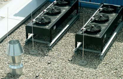
15 light. Nowadays roof areas of industrial and office buildings are often the last installation level. Regardless of the risk of possible lightning strikes, pipes e.g. for ventilation systems, electrical and IT systems are installed on the roof area. All theses systems have electrical links into the building which allow for inducing partial lightning currents. Isolated airtermination systems prevent partial lightning currents from being induced into buildings where they may interfere with or even damage sensitive electrical / electronic equipment. If bare, non-insulated wires of the air-termination system are directly installed on the roof, the separation distance to electric and metal systems situated underneath the roof area has to be observed according to the state of the art and to the current EN lightning protection standard. The separation distance has also to be observed in standard residential buildings with steep roofs. Various conductors, pipes and large metal-coated thermal insulation systems are located close to the air-termination system and downconductor so that the problem of proximity arises. Isolated air-termination systems with high-voltage-resistant down-conductors, s, provide the solution to this problem. The air-termination system is installed e.g. conventionally by means of air-termination rods which are mounted at a GRP pipe for insulation/electrical isolation from the roof. The length of air-termination rods or an arrangement of several air-termination rods is selected in such a way that the protection zone is sufficiently large. If an individual airtermination rod is used, the protection zone is the area formed by the protective angle. If two air-termination rods are used, a tent-shaped protection zone is formed beside the air-termination rods and between these two air-termination rods. If several air-termination rods are arranged, an entire large protection zone is formed below the air-termination rods according to the rolling sphere method. The newly developed light, an extension of the tried and tested DEHNconductor system, offers various design options for external lightning protection systems. There are also connection types of the s light which require no sealing unit for connection to the equipotential bonding element in the connection area. The coupling point at the tripod support has to be effected in a defined way so that a functional earth conductor is not required. This allows for easy installation and consequently saves a lot of time. light
 between roof superstructure and air-termination rod +22 m top edge of the roof S 1 top edge of the roof down-conductor n = 4 17 m building 15 m Isolated air-termination systems for protecting roof")
16 radius = 45 m mesh L 1 = 5 m S 3 (k m 1) h 1 = 2.5 m m top edge roof superstructure S 2 (k m 0.5) between roof superstructure and air-termination rod +22 m top edge of the roof S 1 top edge of the roof down-conductor n = 4 17 m building 15 m Isolated air-termination systems for protecting roof superstructures in consideration of standards concerning the observance of separation distances Design procedure According to the state of the art of lightning protection systems, large roof superstructures should be protected by isolated airtermination systems in case of direct lightning strokes. Electrical isolation of the lightning protection system from conductive parts of the building construction (metal construction parts, reinforcement, etc.) and isolation from electrical conductors in the building prevent lightning currents from flowing through control and supply lines as well as interference / destruction of sensitive electrical and electronic installations.! Building data Building height: Number of down-conductors: Height of roof superstructure: Class of LPS: Building length: Building width: h = 22 m n = 4 units h 1 = 2.5 m III 17 m (maximum distance between down-conductors c = 17 m) 15 m Step 1: Determine the length of the aluminium air-termination rod via the protective angle method or rolling sphere method. Step 2: Calculate the separation distance to determine the position of the air-termination rod. In accordance with the current DIN EN standard, airtermination rods and/or elevated air-termination systems (ring conductors or spanned cables) should be installed taking the calculated separation distance into account in order to protect roof superstructures on buildings against lightning strokes. Three methods can be used for the determining the arrangement and position of air-termination systems: Rolling sphere method Protective angle method Mesh method. The mesh size, the radius of the rolling sphere and the protective angle depend on the class of LPS. The rolling sphere method as universal design method should be used particularly for geometrically complicated applications. A risk analysis in accordance with DIN EN has to be carried out to determine the class of LPS. When using the protective angle method, the protective angle of an air-termination system depends on the selected class of LPS of the lightning protection system and the height of the air-termination system above the area to be protected. Roof superstructure directly connected to the air-termination system!!! is not maintained!!!! The roof superstructure is supposed to be protected by an isolated air-termination rod. 1. Calculation k c (building): k c = n c h k c = = Calculation of s 1 top edge of the roof (side strike): s = k i k c L (m) k m 0.41 s 1 = = 0.72 m Calculation of s 2 between roof superstructure and air-termination rod (k m 0.5): 3 4. Comparison s 3 (k m 1) between roof superstructure and air-termination rod (k m 1): s 3 (k m 1) = s 2 (L1) + s 1 5. Comparison s 2 (k m 0.5) with s 3 (k m 1) s 2 (k m 0.5) = 1.12 m > s 3 (k m 1) = 0.66 Legend: s 2 (L1) = s 3 (k m 1) = ( ) = 0.60 m 0.60 m m = 0.66 m 2 n = total numer of down-conductors c = maximum distance between one down-conductor and the next h = distance (or height) between ring conductors. ok is maintained!!! s 2 (L1) = = 0.40 m s 2 (k m 0.5) = s 1 + s 2 (L1) s 2 = 0.72 m m = 1.12 m Calculation programmes under

17 Distance between Class of LPS I Class of LPS II Class of LPS III Class of LPS IV air-termination radius 20 radius 30 radius 45 radius 60 rods in m sag in m sag in m sag in m sag in m Height of the Class of Class of Class of Class of air-termination LPS I Distance LPS II Distance LPS III Distance LPS IV Distance rod h in m Angle α a in m Angle α a in m Angle α a in m Angle α a in m ROLLING SPHERE Table 3: Sag of the rolling sphere depending on the distance between two air-termination rods and the class of LPS PROTECTIVE ANGLE Values ^= Lightning Protection Guide 2 nd current edition Table (page 55) Table 2: Correlation of the height of the air-termination rod h to the protective angle α and distance a depending on the class of LPS
DEHN + SÖHNE. DEHNiso Distance Holder: The Modular Lightning Protection System.
 DEHN + SÖHNE DEHNiso Distance Holder: The Modular Lightning Protection System. Direct Lightning Strikes. The Protection System. The basic function of an external lightning protection system is to intercept
The innovation in lightning protection High-voltage-resistant, insulated HVI Conductor
 The innovation in lightning protection High-voltage-resistant, insulated HVI Conductor www.dehn-international.com 2 High degree of safety due to controlled discharge of lightning currents Easy to install,
AIR-TERMINATION SYSTEMS AND ACCESSORIES
 102 010 102 075 102 340 102 002 102 003 A Concrete Bases For air termination rods, for protection of minor roof superstructures on flat roofs or for installing distance holders of the DEHNiso Distance
6. Internal lightning protection
 6. Internal lightning protection 6.1 Equipotential bonding for metal installations Equipotential bonding according to IEC 60364-4- 41 and IEC 60364-5-54 Equipotential bonding is required for all newly
TFS / KFSU: Isolating spark gaps with plastic coating and 2 connections (Rd 10 mm) made of stainless
 made of stainless") LIGHTNING EQUIPOTENTIAL BONDING Isolating Spark Gap For lightning equipotential bonding For indirect connection/earthing of functionally isolated installation components when being affected by lightning
LIGHTNING EQUIPOTENTIAL BONDING Isolating Spark Gap For lightning equipotential bonding For indirect connection/earthing of functionally isolated installation components when being affected by lightning
2007 DEHN + SÖHNE / protected by ISO EXFS / 5392
 2007 DEHN + SÖHNE / protected by ISO 16016 EXFS 100 11.12.07 / 5392 Ex Isolating Spark Gaps EXFS 100 (923 100) and EXFS 100 KU (923 101) 2007 DEHN + SÖHNE / protected by ISO 16016 Ex isolating spark gap
RADIO AND TELEVISION SATELLITE EQUIPMENT
 ARTICLE 810 RADIO AND TELEVISION SATELLITE EQUIPMENT Introduction to Article 810 Radio and Television Satellite Equipment This article covers transmitter and receiver (antenna) equipment and the wiring
Isolating Spark Gaps. Isolating spark gaps at an additional earth ring conductor. Isolating spark gaps for Ex zones
 Isolating Spark Gaps Isolating spark gaps at an additional earth ring conductor Isolating spark gaps for Ex zones 187 Protective Spark Gaps For use at roof supports for overhead lines For indirect connection
Use of application-optimised type 1 combined arresters in low-voltage installations
 Use of application-optimised type 1 combined arresters White Paper Contents Use of prewired and application-optimised DEHNshield combined arresters with spark gap technology Examples: Under-road radiators
DESIGN CONSIDERATION OF ELECTRICAL DISTRIBUTION AND LIGHTNING PROTECTION SYSTEMS FOR HIGH-RISE BUILDING
 DESIGN CONSIDERATION OF ELECTRICAL DISTRIBUTION AND LIGHTNING PROTECTION SYSTEMS FOR HIGH-RISE BUILDING 1 LAI LAI WIN, 2 KHIN THUZAR SOE 1 Electrical Power Engineering Department, Mandalay Technological
VBS TBS KTS BSS LFS UFS
 VBS TBS KTS BSS LFS UFS TBS. Surge protection systems Order information and technical data Protection and isolating spark gaps Protection spark gap or isolating spark gap? Isolating spark gaps Protection
On-roof system Alpha + Product catalogue
 On-roof system Alpha + Product catalogue Contents ALPHA +... 3 1. ALPHA + BASE RAILS... 4 2. ALPHA + SPLICES... 5 3. ALPHA + TELESCOPING END PIECES... 6 4. ALPHA + INTER-MODULE CLAMPS AND MODULE END CLAMPS...
Expert 1400 / Expert 3400 Submersible Hydrostatic Level Transmitters
 Expert 1400 / Expert 3400 Submersible Hydrostatic Level Transmitters ll 2G EEx ia llc T6 As our products are continuously improved, we reserve the right to make any change in the stated specifications
Earthing of Electrical Devices and Safety
 Earthing of Electrical Devices and Safety JOŽE PIHLER Faculty of Electrical Engineering and Computer Sciences University of Maribor Smetanova 17, 2000 Maribor SLOVENIA joze.pihler@um.si Abstract: - This
OPTITEMP TT 20 Technical Datasheet
 OPTITEMP TT 20 Technical Datasheet Analog PC-programmable two-wire transmitters for Pt100 Efficient PC-configuration without recalibration Very stable output Very fast response time The documentation is
Power Quality. Case Study. Conrad Bottu Laborelec January 2008
 Case Study Electromagnetic compatibility (EMC) study Breakdown of low voltage electronic equipment in a 25 kv substation Conrad Bottu Laborelec January 2008 Power Quality Power Quality 1 Introduction Description
Test Joints / Fixed Earthing Terminals
 Test Joints / Fixed Earthing Terminals Partially isolated lead-in earthing rod Test joint with disconnecting sleeve Fixed earthing terminal with ring equipotential bonding 131 Disconnecting Sleeves FIXED
The Role of the Grounding System in Electronics Lightning Protection
 ILPS 2016 - International Lightning Protection Symposium April 21-22, 2016 Porto Portugal The Role of the Grounding System in Electronics Lightning Protection Roberto Menna Barreto SEFTIM Brazil Rio de
Polished head, handles black atramentised. Polished head, dip-coated handles. Length mm
 575-576 Steel C 45, oil-hardened and tempered, Pincers (cutting pliers) DIN/ISO 9243 575 Polished head, handles black atramentised. 576 Polished head, dip-coated handles. 575 576 Length 575 576 16 11 18
PUSH-PULL-PROPS. and accessories ROBUSTA-GAUKEL GMBH MOUNTING TECHNOLOGY &CO.KG
 PUSH-PULL-PROPS and accessories MOUNTING TECHNOLOGY ROBUSTA-GAUKEL GMBH &CO.KG MOUNTING TECHNOLOGY PUSH-PULL-PROPS AND ACCESSORIES INDEX General information...................... 3 Push-pull-prop Type
Signal converter for electromagnetic flowmeters
 Quick Start Signal converter for electromagnetic flowmeters Electronic revision: ER 3.0.xx The documentation is only complete when used in combination with the relevant documentation for the flow sensor.
thoroughly tried and tested! EWE Tapping Valves A single system for all types of pipes
 thoroughly tried and tested! EWE Tapping Valves A single system for all types of pipes www.ewe-armaturen.de EWE Tapping Fittings high-quality products from Germany EWE tapping fittings are the product
Lightning Protection / Earthing Main Catalogue 2013/
 Lightning Protection / Earthing Main Catalogue 1/14 single Holders for Air-termination System on Ridge and Hip Tiles For air-termination rods / air-termination rods or spacer bars GRP Ø10 mm double See
Red/Line Selection Guide Surge Protection for Power Supply Systems.
 Red/ine Selection Guide Surge Protection for Power Supply Systems www.dehn.de Power Supply Systems Worldwide International system configurations* according to IEC 60364-1 (DI VDE 0100-100) T-C-System T-S-System
PROMPT TRADING CO. Ph. No.: FOR RESCUE
 FIRED UP FOR RESCUE 78 When it comes to rescuing life and limb, every movement must be just right. This day. Any obstacles in their way, such as a locked access point, present an immediate danger to those
Glass Systems. Technical Information on Pilkington Profilit Profiled Glass with System. - English Edition - Pilkington Profilit
 Glass Systems Technical Information on Profiled Glass with System - English Edition - The - Delivery Programme Glass thickness 6 mm, flange height mm 6 7 0 K 3 8 K//7 3 6 7 6 6 6 6 6 6 50 39 486 K5 6 K3
Wind Transmitter First Class
 THE WORLD OF WEATHER DATA - THE WORLD OF WEATHER DATA - THE WORLD OF WEATHER DATA Instruction for Use 021310/07/06 Wind Transmitter First Class 4.3350.00.000 4.3350.10.000 ADOLF THIES GmbH & Co. KG Hauptstraße
Field Instruction. Induced voltages can occur in overhead lines, underground cables, or in switchyards.
 8.3 Induced Voltage Purpose The purpose of this instruction is to provide awareness of Electrostatic and Electromagnetic induced voltages and the method required to reduce or eliminate it. An induced voltage
Installation instructions and notes on implementation of an intermeshed equipotential bonding system with EMClots
 Installation instructions and notes on implementation of an intermeshed equipotential bonding system with EMClots Project: Project key: Project management: Responsible for the lot: Revision number Created
BASIC PROBLEMS AND SOLUTION OF THE ENCAPSULATION OF A LOW VOLTAGE SPARK GAP WITH ARC SPLITTER CHAMBER
 Journal of ELECTRICAL ENGINEERING, VOL. 63, NO. 2, 2012, 103 108 BASIC PROBLEMS AND SOLUTION OF THE ENCAPSULATION OF A LOW VOLTAGE SPARK GAP WITH ARC SPLITTER CHAMBER L udovít Hüttner L udovít Jurčacko
The Lightning Event. White Paper
 The Lightning Event White Paper The Lightning Event Surge Protection Solutions for PTC 1 The Lightning Event There are volumes of information available on what we believe lightning is and how we think
Investigation of skin effect on coaxial cables
 Investigation of skin effect on coaxial cables Coaxial cables describe a type of cables that has an inner conductor surrounded by an insulator, which is surrounded by another layer of conductor and insulator
Components made of special materials. Floor Elements for Profile St Profile KH. Fastening Elements for Profile KH
 Profile Fastening Elements for Profile Floor Elements for Profile Profile KH Fastening Elements for Profile KH Components made of special materials Products in this section Profile 8 x eel profile that
Construction manual for 50 MHz XL design yagi-kits
 Construction manual for 50 MHz XL design yagi-kits Source: http://www.nuxcom.de/pdf/nuxcom_construction-manual_6m-xl.pdf Please check if all parts listed in the invoice are delivered with the kit. In the
Adjustable Feet Castors Accessories for Floor Elements
 Adjustable Feet Castors Accessories for Floor Elements Products in this section Levelling Knuckle Feet Threaded spindles for infinite height adjustment Metal or plastic foot plate Knuckle Feet X Compatible
Wind Transmitter First Class / 141 / / 141 / 161
 THE WORLD OF WEATHER DATA - THE WORLD OF WEATHER DATA - THE WORLD OF WEATHER DATA Instruction for Use 021436/01/07 Wind Transmitter First Class 4.3350.00.140 / 141 / 161 4.3350.10.140 / 141 / 161 ADOLF
INSTALLATION INSTRUCTIONS TRI-ROOF. energy for a better world
 energy for a better world INSTALLATION INSTRUCTIONS TRI-ROOF The flexible roof integration system Compatible for framed module types* Simple exchange of modules Replaces existing roofing Special profiles
Outdoor Installation 2: Lightning Protection and Grounding
 Outdoor Installation 2: Lightning Protection and Grounding Training materials for wireless trainers This one hour talk covers lightning protection, grounding techniques and problems, and electrolytic incompatibility.
FRP GATES MM08 FRP GATES Rev. 3 COMPOSITE SOLUTION PAGE 1
 FRP GATES MM08 08.02.2016 Rev. 3 FRP GATES COMPOSITE SOLUTION PAGE 1 SUMMARY 1. USES AND CHARACTERISTICS... 3 2. EMPLOYMENT FIELDS... 4 3. MATERIALS... 5 3.1 TABLE OF PROFILES AND STRUCTURAL ACCESSORIES...
METRISO. Analog Insulation, Low Resistance and Voltage Measurement Instrument /9.14
 3-349-813-3 1/9.14 Insulation measurement per EN 61557-2/VDE 413, part 2 Test voltages: 5 V, 1 V, 25 V, 5 V and 1 V Analog display of measured values and limit values Intelligent filter precise and measurement-dependent
CHIP AND DUST EXTRACTION SYSTEMS
 CHIP AND DUST EXTRACTION SYSTEMS For connecting to all wood processing machines Healthy air at the workplace: Clean air clean work High suction output Mobile use, easy to connect Large range of accessories
Protection against unacceptable voltages in railway systems
 Bernhard Richter*, Alexander Bernhard*, Nick Milutinovic** SUMMERY Based on the system voltages for AC and DC railway systems the required voltage ratings for modern gapless MO surge arresters are given.
HP ProCurve 6.9/7.7dBi Dual Band Directional Antenna (J8999A) Guide
 Guide") HP ProCurve 6.9/7.7dBi Dual Band Directional Antenna (J8999A) Guide SAFETY The HP ProCurve J8999A and all associated equipment should be installed in accordance with applicable local and national electrical
HP ProCurve 6.9/7.7dBi Dual Band Directional Antenna (J8999A) Guide SAFETY The HP ProCurve J8999A and all associated equipment should be installed in accordance with applicable local and national electrical
Overview of Grounding for Industrial and Commercial Power Systems Presented By Robert Schuerger, P.E.
 Overview of Grounding for Industrial and Commercial Power Systems Presented By Robert Schuerger, P.E. HP Critical Facility Services delivered by EYP MCF What is VOLTAGE? Difference of Electric Potential
ASSEMBLY INSTRUCTIONS. Construction type approved Reg. no S819 F ENERGY AND SANITARY SYSTEMS
 Heliostar 252 S4 and 218 S4 FREE-STANDING INSTALLATION vertical ASSEMBLY INSTRUCTIONS Construction type approved Reg. no. 011-7S819 F ENERGY AND SANITARY SYSTEMS Safety instructions Safety instructions
HV Module Systems for Testing, Training and Research
 HV Module Systems for Testing, Training and Research 4.0/3 Application Advantages Principle of HV circuit Smaller high-voltage (HV) test systems are necessary for research, development and quality testing
Model Number Structure. Ordering Information. Solid-state Power OFF-delay Timer H3DE-H. Model Number Legend. List of Models
 Solid-state Power OFF-delay Timer H3DE-H Timers Two delay-time models available. 0.1 to 12 seconds (S Series) 1 to 120 seconds (L Series) Covers wide range of supply voltage. Model Number Structure Model
MEDIUM VOLTAGE PRODUCT. KOKM Cable current instrument transformers Instruction for Installation, use and maintenance
 MEDIUM VOLTAGE PRODUCT KOKM Cable current instrument transformers Instruction for Installation, use and maintenance 2 KOKM CABLE CURRENT INSTRUMENT TRANSFORMERS INSTRUCTION FOR INSTALLATION, USE AND MAINTENANCE
Dust removal filters for combustible dusts Information
 MAHLE Industrialfiltration is now Filtration Group. For more information, visit www.filtrationgroup.com Information ATEX-compliant dust removal filters Features Explosion protection is stipulated for combustible
CHAPTER 15 GROUNDING REQUIREMENTS FOR ELECTRICAL EQUIPMENT
 CHAPTER 15 GROUNDING REQUIREMENTS FOR ELECTRICAL EQUIPMENT A. General In a hazardous location grounding of an electrical power system and bonding of enclosures of circuits and electrical equipment in the
Rod probe With coaxial tube reference probe
 Capacitive level transmitters GENERAL DESCRIPTION NIVOCAP 2-wire capacitive level transmitters provide an ideal solution for level measurement of conductive or non-conductive liquids. The probe of the
Installation & Operating Manual. iwap202
 Installation & Operating Manual iwap202 This page is intentionally left blank. Document Number 409345 (based on 407655) (See Last Page for Revision Details) For warranty information, refer to Terms and
Medium Voltage Power Cables
 N2XSY 6/0, /20, /30 NA2XSY 6/0, /20, /30 N2XS2Y 6/0, /20, /30 NA2XS2Y 6/0, /20, /30 N2XS(F)2Y 6/0, /20, /30 NA2XS(F)2Y 6/0, /20, /30 N2XSEY 3 x 6/0 Medium Voltage Power Cables Photo: HELUKABEL Q 47 Medium
GMS FLEX. / Versatile mounting system for open-terrain PV power plants / Adaptable to terrain: Variable module tilt angle and lateral tilt, various
 GMS FLEX Adjustable and flexible as the nature / Versatile mounting system for open-terrain PV power plants / Adaptable to terrain: Variable module tilt angle and lateral tilt, various foundation types
Cable Management Solutions with DLP TM
 DLP trunking system P. 374-375 Selection chart for DLP trunking system P. 397 Floor boxes & Under floor boxes Technical data P. 373 DLP U-PVC adaptable trunking system Cable Management Solutions with DLP
Installation Manual. This installation is for the Odyssey H1800 Series Ventilation System.
 Installation Manual This installation is for the Odyssey H1800 Series Ventilation System. This installation is limited to roofs with pitches between 3 and 35. This instruction assumes that there is a power
Wall flashing profiles FP 60 WA 1 WA 150 WA 1 - ÜK WA 1 - Ü 150 E
 Wall flashing profiles FP 60 WA 1 WA 150 WA 1 - ÜK 150-275 WA 1 - Ü 150 E 1 F Ü R D I E ZU K U N FT G E DAC HT. The alwitra waterproofing system alwitra wall flashing profiles are part of the practically
Safety earthing. Sector Energy PTI NC. Copyright Siemens AG All rights reserved. Theodor Connor
 Safety earthing Sector Energy PTI NC Theodor Connor Copyright Siemens AG 2008. All rights reserved. Content Introduction Theoretical background Soil Analysis Design of earthing system Measurements on earthing
SPECIFICATION FOR STEP UP TRANSFORMER 0.415/11Kv and (630KVA & 1000KVA)
") SPECIFICATION FOR STEP UP TRANSFORMER 0.415/11Kv and (630KVA & 1000KVA) 0.415/33kV DESIGN AND CONSTRUCTION General 1. The transformer shall be three phase, oil immersed type, air cooled, core type, outdoor
SPECIFICATION FOR STEP UP TRANSFORMER 0.415/11Kv and (630KVA & 1000KVA) 0.415/33kV DESIGN AND CONSTRUCTION General 1. The transformer shall be three phase, oil immersed type, air cooled, core type, outdoor
LIGHTNING EARTHING SYSTEM : A PRACTICAL GUIDE
 International Lightning Protection Association 1 st Symposium Valencia Spain 24th 25th of November, 2011 LIGHTNING EARTHING SYSTEM : A PRACTICAL GUIDE Alain Rousseau SEFTIM (France) ABSTRACT To make a
3.7 Grounding Design for EAST Superconducting Tokamak
 3.7 Design for EAST Superconducting Tokamak LIU Zhengzhi 3.7.1 Introduction system is a relevant part of the layout of Tokamak. It is important and indispensable for the system reliability and safety on
MANUAL MOUNTING SYSTEM FOR BITUMEN / EPDM
 MANUAL MOUNTING SYSTEM FOR BITUMEN / EPDM EN mounting system for insulated pitched roof Bitumen / EPDM for solar panels landscape setup ESDEC BV 2015 TABLE OF CONTENT 1. Introduction 1 2. General installation
ALUMINIUM SOLAR MOUNTING SYSTEM. Components catalogue FOR ALL TYPES OF ROOFS AND SITES
 Components catalogue MOUNTING RAILS CARRIERS FOR RAILS FASTENERS BOLTS AND NUTS CLIPS FLAT ROOFS STRUCTURES FREE FIELD SYSTEMS COMPLEX ROOFS SYSTEMS ALUMINIUM SOLAR MOUNTING SYSTEM FOR ALL TYPES OF ROOFS
Diagonal Cutters for plastics DIN ISO
 Diagonal Cutters for plastics DIN ISO 5746 72 > cutting face flush ground > for nearly flush cutting of moulded plastic components from sprues > cuts soft materials such as lead in a flush cut > with opening
Contents. Technical Metal Industrial Co. L.L.C.
 We, at Technical Metal Industrial Co. L.L.C. take pride in declaring the company s commitment to satisfy our customers by providing high quality products and promptly delivering them as per the agreed
Installation Manual for Gate Guard
 Installation Manual for Gate Guard Fast Opening Barrier Gate for Emergencies and Contra Flow Innovative safety technology from SGGT of Germany TABLE OF CONTENTS Page Number Preface 3 Introduction 3 System
RoamAbout Outdoor Antenna Site Preparation Guide
 9033153 RoamAbout 802.11 Outdoor Antenna Site Preparation Guide Notice Notice Cabletron Systems reserves the right to make changes in specifications and other information contained in this document without
Technical Specification FLUXUS ADM 8127B
 FLUXUS ADM 8127B Liquid Ultrasonic Flowmeter for Permanent Installation in Hazardous Areas in the Mining Environment FLUXUS ADM 8127B is especially designed for the stationary use in explosive atmosphere
Electrical height adjustment. ... easy & reliable. Multilift II telescope Multilift II. Synchron
 Electrical height adjustment... easy & reliable 07/2017 Multilift II telescope Multilift II Synchron Preface The Multilift lifting column has been tried-and-tested over many years in many customer applications.
OIL-IMMERSED ARC-SUPPRESSION COILS
 ISO 9001:2000 99-320 Żychlin, ul. Narutowicza 70 ISO 14001:2004 PN-N-18001:2004 www.ftz.pl Secretary s Office Tel.: +48 24 285 46 05, Fax: +48 24 285 46 31 zarzad@ftz.pl Sales and Marketing Department
Wind Transmitter First Class Advanced Classified according to IEC ( )
") THE WORLD OF WEATHER DATA - THE WORLD OF WEATHER DATA - THE WORLD OF WEATHER DATA Instruction for Use 021519/01/09 Wind Transmitter First Class Advanced Classified according to IEC 61400-12-1 (2005-12)
THE WORLD OF WEATHER DATA - THE WORLD OF WEATHER DATA - THE WORLD OF WEATHER DATA Instruction for Use 021519/01/09 Wind Transmitter First Class Advanced Classified according to IEC 61400-12-1 (2005-12)
OPTIWAVE 7300 C Supplementary instructions
 OPTIWAVE 7300 C Supplementary instructions Radar (FMCW) Level Transmitter for agitated liquids in process applications Supplementary Instructions for ATEX applications KROHNE CONTENTS OPTIWAVE 7300 C General
ABSTRACTS of SESSION 6
 ABSTRACTS of SESSION 6 Paper n 1 Lightning protection of overhead 35 kv lines by antenna-module long flashover arresters Abstract: A long-flashover arrester (LFA) of a new antenna-module type is suggested
Best Practices for Power and Transient Protection on Rosemount Radar Transmitters
 Technical Note Rosemount Radar Transmitters Best Practices for Power and Transient Protection on Rosemount Radar Transmitters BACKGROUND INTRODUCTION This document describes best practices for power and
ADS. Antenna-Disconnect-Switch. To protect your radio equipment from damage due to surge voltages. Assembly and Operation Manual
 Antenna-Disconnect-Switch To protect your radio equipment from damage due to surge voltages Assembly and Operation Manual Table of Content Introduction... 2 Functional diagram... 2 Electrical characteristics...
Signal converter for electromagnetic flowmeters
 IFC 100 Quick Start Signal converter for electromagnetic flowmeters Electronic revision: ER 3.1.2_ The documentation is only complete when used in combination with the relevant documentation for the flow
Simplex Baseboard System Baseboard System
 Simplex Baseboard System Baseboard System I Complete installation programme I Trouble-free and time-saving installation I Various connection kits for all types of pipe Our service to you I Simplex Products
7P Series - Surge Protection Device (SPD) Features 7P P P
 Features 7P P P") Features 7P.09.1.255.0100 7P.01.8.260.1025 7P.02.8.260.1025 SPD Type 1+2 Surge arrester range - single phase system / three phase system Surge arresters suitable in low-voltage applications in order to
Features 7P.09.1.255.0100 7P.01.8.260.1025 7P.02.8.260.1025 SPD Type 1+2 Surge arrester range - single phase system / three phase system Surge arresters suitable in low-voltage applications in order to
THE OZIPOLE Mk II A Portable Multiband Dipole Bob VK5AFZ
 THE OZIPOLE Mk II A Portable Multiband Dipole Bob VKAFZ Many amateurs might be familiar with the Ozipole, a small portable loaded dipole for the m to m bands. It was designed by Peter VKEVB and supplied
Copyright Black Box Corporation. All rights reserved.
 Copyright 2004. Black Box Corporation. All rights reserved. 1000 Park Drive Lawrence, PA 15055-1018 724-746-5500 Fax 724-746-0746 JULY 2004 LW6200A LW6201A Pure Networking 2.4-GHz Antennas CUSTOMER SUPPORT
LF Conductivity Measuring Probe
 LF Conductivity Measuring Probe Contents 1 General 1.1 Introduction 1.2 Application range 2 Safety 2.1 Warnings and symbols 3 Transport and storage 4 Application 5 Measuring principle 6 Assembly 7 Construction
Installation Instructions
 Installation Instructions SOLC 220 SOLC 220 PAG SOLC 220 PAE SOLC 220 BAG SOLC 220 BAE Flat plate collector Basic kit Frankfurt tile Extension kit Frankfurt tile Basic kit plain tile Extension kit plain
Industrial Wall Fan SAX Installation and Maintenance Instructions
 Industrial Wall Fan SAX Installation and Maintenance Instructions THESE INSTRUCTIONS MUST BE READ FULLY BEFORE COMMENCING INSTALLATION Code Supply Amps Watts r/min dba @ 3m SAX23/9A 230V/1Ph/50Hz 0.20
First Revision No. 141-NFPA [ Global Input ]
![First Revision No. 141-NFPA [ Global Input ]](/thumbs/85/92711160.jpg "First Revision No. 141-NFPA [ Global Input ]") of 161 2/8/2018, 2:49 PM First Revision No. 141-NFPA 780-2017 [ Global Input ] In Annex L text, tables and formulas replace all symbols with lower case italics r and upper case subscripts with lower case
of 161 2/8/2018, 2:49 PM First Revision No. 141-NFPA 780-2017 [ Global Input ] In Annex L text, tables and formulas replace all symbols with lower case italics r and upper case subscripts with lower case
Practical Lightning Mitigation
 Practical Lightning Mitigation Jerry Hogan MBA, BSEE Director of Engineering, Solara Technical Sales Jerry Hogan, MBA, BSEE Director of Eng. Solara Technical Sales BSEE, University of Colorado MBA, University
TZ-RD-1740 Rotary Dipole Instruction Manual
 TZ-RD-1740 17/40m Rotary Dipole Instruction Manual The TZ-RD-1740 is a loaded dipole antenna for the 40m band and a full size rotary dipole for the 17m band. The antenna uses an aluminium radiating section
German Cathodic Protection
 SURGE PROTECTION Spark gap: EXFS L Document No.: 4-0-R Sheet: of Ex isolating spark gaps EXFS L are used for conductive system parts which cannot be interconnected directly in hazardous zones. This includes,
6.1. PUSH-PULL-PROPS and accessories
 6 6.1. PUSH-PULL-PROPS and accessories MOUNTING TECHNOLOGY 6 GENERAL INFORMATION PUSH-PULL-PROPS AND ACCESSORIES INDEX General information....................... 3 Push-pull-props Type R.....................
Wind Transmitter - with frequency output xx.xxx
 THE WORLD OF WEATHER DATA - THE WORLD OF WEATHER DATA - THE WORLD OF WEATHER DATA Instruction for Use 021531/11/09 Wind Transmitter - with frequency output 4.3303.xx.xxx ADOLF THIES GmbH & Co. KG Hauptstraße
BAR-ANT-N-N-EX. Antenna barrier for the hazardous area. Data sheet. 1 Description
 BAR--N-N-EX Antenna barrier for the hazardous area Data sheet 060_en_00 PHOENIX CONTACT 05-06-0 Description Using an antenna barrier, you can execute HF outputs of wireless modules with intrinsic safety.
Expert 1400 / Expert 3400 Submersible Hydrostatic Level Transmitters
 Expert 1400 / Expert 3400 Submersible Hydrostatic Level Transmitters Class l, Division 1 Group A-D IIC T4 As our products are continuously improved, we reserve the right to make any change in the stated
Lightning Strikes. Presented to the Greater Norwalk Amateur Radio Corporation Inc. February 8, 2017 Steven M. Simons W1SMS
 Lightning Strikes Presented to the Greater Norwalk Amateur Radio Corporation Inc. February 8, 2017 Steven M. Simons W1SMS ARRL CT State Technical Coordinator The Power of Lightning What is a Ground? Design
INSTALLATION AND OPERATING INSTRUCTIONS
 Labkotec Oy Labkotie 1 FI-36240 KANGASALA FINLAND Tel. +358 29 006 260 Fax +358 29 006 1260 Internet: www.labkotec.fi 26.09.2008 1 / 5 Capacitive level sensor KAS/3W INSTALLATION AND OPERATING INSTRUCTIONS
EMC Philosophy applied to Design the Grounding Systems for Gas Insulation Switchgear (GIS) Indoor Substation
 Indoor Substation") EMC Philosophy applied to Design the Grounding Systems for Gas Insulation Switchgear (GIS) Indoor Substation Marcos Telló Department of Electrical Engineering Pontifical Catholic University of Rio Grande
EMC Philosophy applied to Design the Grounding Systems for Gas Insulation Switchgear (GIS) Indoor Substation Marcos Telló Department of Electrical Engineering Pontifical Catholic University of Rio Grande
Agenda. Earthing of Telecom Installations using Single Point Earthing. Reference Documents. How many earths? Earthing Issue...
 Earthing of Telecom Installations using Single Point Earthing R. Saji Kumar DGM (IT) O/o The Chief General Manager Trivandrum Agenda Reference Documents Earthing Issue & the Problems Earthing Principle
MIG/MAG Welding Torch ABIMIG 645 W liquid-cooled
 MIG/MAG Welding Torch ABIMIG 645 W liquid-cooled C E R DIN EN ISO 9001 Q M T - I F S I Y E T S D E M ABICOR BINZEL. The right welding torch for every job! BINZEL air cooled welding torches incorporate
Operating Manual * * Differential pressure transmitter. Table of Contents. 1 Safety guidelines. 1.1 General Information
 *09005137* BA_EN_DE50 Rev.A 11/12 *09005137* d e v e l o p i n g s o l u t i o n s DE50 Operating Manual Differential pressure transmitter Table of Contents 1 Safety guidelines 2 Application purpose 3
Installation instructions. Novotegra for Corrugated Fibre Cement / Sandwich Roofs
 Installation instructions Novotegra for Corrugated Fibre Cement / Sandwich Roofs I CONTENTS 1 General information... 0 2 Novotegra: mounting system planning... 1 2.1 Solar-Planit software... 1 2.1.1 General
Wind Transmitter - with analogue output xxx
 THE WORLD OF WEATHER DATA - THE WORLD OF WEATHER DATA - THE WORLD OF WEATHER DATA Instruction for use 020856/10/07 Wind Transmitter - with analogue output 4.3303.22.xxx ADOLF THIES GmbH & Co. KG Hauptstraße
Alufix Basic Sets offer a variety of application possibilities based on the quantity of components (from 19 to over 440) and their composition
 and their composition") ALUFIX BASIC SETS 2 ALUFIX BASIC-SETS Alufix Basic Sets offer a variety of application possibilities based on the quantity of components (from 19 to over 440) and their composition ALUFIX BASIC-SETS Note:
ALUFIX BASIC SETS 2 ALUFIX BASIC-SETS Alufix Basic Sets offer a variety of application possibilities based on the quantity of components (from 19 to over 440) and their composition ALUFIX BASIC-SETS Note: