Installation & Operating Manual. iwap202
|
|
|
- Charleen Booth
- 5 years ago
- Views:
Transcription


1 Installation & Operating Manual iwap202
2 This page is intentionally left blank. Document Number (based on ) (See Last Page for Revision Details) For warranty information, refer to Terms and Conditions at Extronics Limited. This document is Copyright Extronics limited. Extronics reserve the right to change this manual and its contents without notice, the latest version applies. 2
3 Contents 1 Introduction Safety Information and Notes Storage of this Manual Special Conditions of Safe Use ATEX List of Notes Installation and Setting-to-Work Wall mount fixing Fixing instruction, pillar mount Installation Removing the cover Power Supply Fitting the Cables Ethernet Cable Installation RJ45 Ethernet Cable Option RJ45 Screw Terminal Option Earthing Intrinsically Safe RF Outputs Antenna Requirements Antenna Installation Setting to work Intended Purpose Usage Transportation and Storage Authorized Persons Cleaning and Maintenance Cleaning and Maintenance Intervals Aggressive substances and environments Exposure to external stresses Label Drawing EU Declaration of Conformity Manual Revision
4 1 Introduction Operating Manual The iwap202 Zone 2 Access Point Enclosure is designed to deploy wireless networks in hazardous areas. The concept allows installation of equipment from leading WLAN vendors such as Cisco, Aruba and Firetide. Each type of Access Point or RF transmitting device is rigorously checked and tested by Extronics and our Notified Body to ensure conformity to the ATEX standards and approvals. This means that Extronics can provide an OEM a solution to enable your WLAN network devices to be installed in hazardous areas. The Extronics iwap202 is designed for use with one to six standard antennas or Extronics iant200 series of antennas for optimum coverage on Chemical Plants, Oil Refineries or Oil & Gas Platforms. Optional features include surge arrestors for lightening suppression in outdoor installations plus the option of plug and socket cable entry instead of cable glands. 4
5 2 Safety Information and Notes 2.1 Storage of this Manual Keep this user manual safe and in the vicinity of the device. All persons who have to work on or with the device should be advised on where the manual is stored. 2.2 Special Conditions of Safe Use ATEX The apparatus is not capable of withstanding the 500V insulation test required by clause of EN :2005. This must be taken into account when installing the apparatus. Refer to manufacturers instruction manual for guidance. All cable glands, blanking elements and thread adapters shall be certified to a minimum II 3 G IIC, II 2 D IIIC, provide a minimum degree of protection of IP64 and have an ambient range suitable for installation. External antenna connections must be shielded from ultraviolet radiation with either a cap or an antenna. The isolate500 or isolate501 enclosure must be earthed through its mounting to an earthed chassis or with an earth bond wire with a cross section area of at least 4mm². It is considered inappropriate to provide conventional IS parameters for this equipment. For connection to external antenna refer to the information in the manufacturers instruction manual for clarification of the antenna requirements and calculation of the RF output power. 2.3 List of Notes The notes supplied in this chapter provide information on the following. Danger / Warning. o Possible hazard to life or health. Caution o Possible damage to property. Important o Possible damage to enclosure, device or associated equipment. Information o Notes on the optimum use of the device Installation of the iwap202 must be performed in accordance with EN , EN and EN Maintenance and inspection must be performed in accordance with EN Installation of the iwap202 is only to be performed by skilled electricians and instructed personnel in accordance with national legislation. The iwap202 contains INTRINSICALLY SAFE circuits. DO NOT OPEN MAINTAIN OR SERVICE IN AN AREA WHERE AN EXPLOSUVE ATMOSPHERE MAY BE PRESENT 5
6 Changes in the design and modifications to the equipment are not permitted. Changing of the pre-installed wireless devices is NOT permitted. The iwap202 Intrinsically Safe RF output ports are located in the positions shown in [IS output position diagram]. Only antennas in accordance with [antenna requirements section] may be connected to these ports. Refer to section [antenna installation] for antenna installation requirements. The iwap202 MUST be earthed. Refer to Section [earthing] for details. The IWAP202 shall be operated as intended and only in an undamaged condition. The IWAP202 must not be stored or operated outside of its rated temperature range as stated on the ATEX certificates. If cable glands different to those supplied by Extronics are used, these must be M20-sized cable glands meeting the requirements of EN for ATEX Category 2G and ATEX Category 2D equipment, and must not compromise the IP66 rating of the iwap202 enclosure. The nylon washers on the underside of the enclosure lid must be used with the gasket to maintain the IP rating of the enclosure. Although antennas connected to the Intrinsically Safe RF outputs of the iwap202 may be installed in Zone 0, Zone 1 or Zone 20 hazardous areas, the iwap202 enclosure must NOT be installed in these environments. Do not exceed the RF Threshold Power for the equipment group in which the iwap202 and its antennas are to be installed; it must be controlled in accordance with IEC , and must not exceed the following levels: IIC 2W (+33dBm) IIB 3.5W (+35.4dBm) IIA 6W (+37.7dBm) III 6W (+37.7dBm) The iwap202 frame earth is connected directly to circuits within the enclosure. It is not capable of withstanding the 500V insulation test required by clause of EN :2010. This must be taken into account when installing the equipment Information Once all cables are connected correctly, refit the enclosure lid using the four screws previously removed. Use a torque screwdriver set to 2.5 Nm. Do not over-tighten screws. 6
7 3 Installation and Setting-to-Work 3.1 Wall mount fixing 7
 Item Description Quantity 1 Unistrut channel, 41mm x 21mm, 300mm (11 3/4 approx.")
, 316 ST/ST 3 Unistrut spring nuts M8, 316 ST/ST 4 4 Socket head screw M8 x 20, A4-70 4 5 M8 plain washer, A4 4 1.")
8 3.2 Fixing instruction, pillar mount Contents of optional mounting kit (Extronics part number IWAPMB04) Item Description Quantity 1 Unistrut channel, 41mm x 21mm, 300mm (11 3/4 approx.) 2 long, 316 ST/ST 2 Unistrut pipe clamp for Ø58.7mm to Ø 63.5mm (Ø 2¼ to Ø 2 2½ ), 316 ST/ST 3 Unistrut spring nuts M8, 316 ST/ST 4 4 Socket head screw M8 x 20, A M8 plain washer, A First, slide the pipe clamps into each piece of unistrut channel. Check that the orientation of each side of the clamp is correct. 2. Attach the unistrut channels, horizontally, to the mounting points on the corners of the iwap20x enclosure using the spring nuts and the M8 screw. 8


9 3. Offer the iwap20x to the pole and secure the clamps around the pole using the bolts provided with the clamps. 4. Once the pipe clamps have been fastened and the hex bolts are tightly secured, the enclosure will be mounted. 9
10 3.2.2 Installation The IWAP202 is simple to install and can be secured directly to suitable surface using the mounting holes on the Enclosure. 10
, with up to three antennas for each radio.")
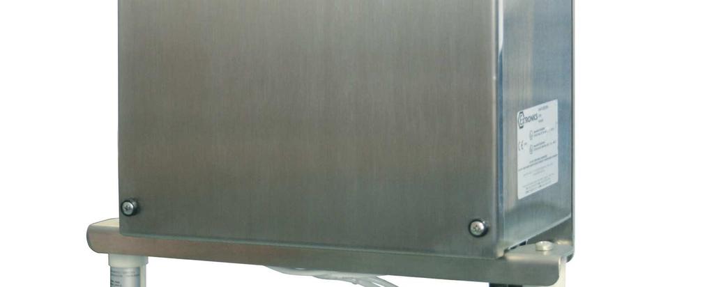
11 3.3 Removing the cover Unscrew the four screws and remove the enclosure lid. The example picture and tables below show details for an iwap202 fitted with a two radio Access Point (AP), with up to three antennas for each radio. There are many AP variations available, another common type being a single radio, dual frequency version, where the tables below are not applicable, as each antenna output is dual frequency (both 2.4 and 5 GHz on the same radio). Lid screws R1-C R1-B R1-A Lid screws Ethernet /Fibre Cable Entry AC/DC Power Cable Entry R2-C R2-B R2-A See table below for antenna connections: Antenna Connection Number of N-type connectors ordered for Radio 1 (2.4GHz Default) R1-A x R1-B x x R1-C x x x Antenna Connection Number of N-type connectors ordered for Radio 2 (5GHz Default) R2-A x R2-B x x R2-C x x x Note: For Radio 1 (R1) and Radio 2 (R2) on any manufacturers Wireless Access point, A will be antenna port 1, B will be antenna port 2, and C will be antenna port 3. For example: If you have ordered 1 N-type connector for Radio 1, and 2 N-type connectors for Radio 2. Then R1-A will be connected to antenna port 1 of Radio 1, R2-A will be connected to antenna port 1 of Radio 2, and R2-B will be connected to antenna port 2 of Radio 2 for any manufacturers wireless access point. 11

12 3.3.1 Power Supply The iwap202 may only be powered from an IEEE 802.3af POE or IEEE 802.3at POE+ power source. The equipment rating plate identifies which power supply type is required for a specific variant Fitting the Cables All cables should be connected to the IWAP202 via the correct cable gland, fitted by a competent person. If cable glands different to those supplied by Extronics are used, these must be M20-sized cable glands meeting the requirements of EN :2012 for ATEX Category 2 GD equipment, and not compromise the IP66 rating of the IWAP202 enclosure. The installer MUST ensure that that all cables have adequate mechanical protection to avoid damage Ethernet Cable Installation Pass the Ethernet cable through the gland, and terminate in an RJ45 connector. Plug into the Ethernet input socket as shown (15). Ensure the gland is correctly sized for the cable used, and fully tight RJ45 Ethernet Cable Option 4 =Access point, 5 = Extronics isolate500 or isolate501 providing Ex is RF outputs 6 = RF connectors, 15 = Ethernet surge arrestor with RJ45 connector. 22 = Option lightning surge arrestor 12

13 3.3.5 RJ45 Screw Terminal Option Wire into item 23 Ex e Screw terminals Operating Manual Minimum cross section of cable = 0.14mm 2 Maximum cross section of cable = 1.5mm Earthing The iwap202 MUST be securely earthed with a minimum 4mm 2 cable using the External M6 Earth Stud. 13
14 The iwap202 frame earth is connected directly to circuits within the enclosure. It is not capable of withstanding the 500V insulation test required by clause of EN :2010. This must be taken into account when installing the equipment 3.4 Intrinsically Safe RF Outputs The iwap202 Intrinsically Safe RF output ports are located in the positions shown in [IS output position diagram]. Only antennas in accordance with [antenna requirements section] may be connected to these ports. Refer to section [antenna installation] for antenna installation requirements. Although antennas connected to the Intrinsically Safe RF outputs of the iwap202 may be installed in a hazardous areas requiring Category 1 equipment, the iwap202 enclosure must NOT be installed in these environments. Do not exceed the RF Threshold Power for the equipment group in which the iwap202 and its antennas are to be installed; it must be controlled in accordance with IEC , and must not exceed the following levels: IIC 2W (+33dBm) IIB 3.5W (+35.4dBm) IIA 6W (+37.7dBm) III 6W (+37.7dBm) The RF outputs of the iwap202 using isolate500 are approved as: Ex ia IIC Ga Ex ia IIIC Da Um = 253Vr.m.s The RF outputs of the iwap202 using isolate501 are approved as: Ex ia IIC Ga Ex ia IIIC Da Um = 250Vr.m.s 3.5 Antenna Requirements Antennas connected to the iwap202 Intrinsically Safe RF outputs must be assessed as simple apparatus in accordance with IEC Antennas supplied by Extronics for use with the iwap202 already meet these requirements. It is possible to assess other antennas for this purpose, contact Extronics for details. 14
15 3.6 Antenna Installation Antennas approved by Extronics for use with the iwap202 may either be fitted directly to the RF connectors of the iwap202, or via a length of coaxial cable. If antennas are sited remotely from the iwap202 flameproof enclosure, any metallic parts of the antennas must be isolated from earth by > 500Vr.m.s, to prevent hazardous earth currents from flowing in the coaxial cable Setting to work Ensure the lid is secure, correct cable glands are fitted and the unit device correctly wired and earthed for the particular application before applying power Ensure that the lid gasket is clean and undamaged before fitting the lid. Once all cables are connected correctly, refit the enclosure lid using the four screws previously removed. Use a torque screwdriver set to 2.5 Nm. Do not over-tighten screws. 4 Intended Purpose Usage Installation of the iwap202 must be performed in accordance with EN , EN and EN Maintenance and inspection must be performed in accordance with EN Important Before setting the units to work read the technical documentation carefully. Important The latest version of the technical documentation or the corresponding technical supplements is valid in each case. The IWAP202 is built using modern components and is extremely reliable in operation; however it must only be used for its intended purpose. Please note that the intended purpose also includes compliance with the instructions issued by the manufacturer for installation, setting up and service. Any other use is regarded as conflicting with the intended purpose. The manufacturer is not liable for any subsequent damage resulting from such inadmissible use. The user bears the sole risk in such cases. 4.1 Transportation and Storage All IWAP202 devices must be so transported and stored that they are not subjected to any excessive mechanical stresses. 15
16 4.2 Authorized Persons Only persons trained for the purpose are authorized to handle the IWAP202; they must be familiar with the unit and must be aware of the regulation and provisions required for correct installation as well as the relevant accident prevention regulations. 4.3 Cleaning and Maintenance The IWAP202 and all its components require no maintenance and are selfmonitoring. All work on the IWAP202 by personnel who are not expressly qualified for such activities will cause the guarantee to become void. 4.4 Cleaning and Maintenance Intervals The cleaning intervals depend on the environment where the system is installed. 4.5 Aggressive substances and environments The IWAP202 is not designed to come into contact with aggressive substances or environments, please be aware that additional protection may be required. 4.6 Exposure to external stresses The IWAP202 is not designed to be subjected to excessive stresses e.g. vibration, heat, impact. Additional protection is required to protect against these external stresses. The IWAP202 will require additional protection if it is installed in a location where it may be subjected to damage. 16
17 5 Label Drawing AAA: Supply voltage e.g. POE/POE+; BBB: Supply current, e.g. POE/POE+; CCC: Supply frequency e.g. POE/POE+; length DDD: Production option codes, configuration-dependent, unlimited length EEEE: Notified body number for production MAC1/MAC2 are optional Ethernet MAC addresses for the internal hardware, and may not be present 17
18 6 EU Declaration of Conformity 18
19 19
20 7 Manual Revision Revision Description Date By 1.0 Initial Release 18/12/2014 AR 1.1 isolate501 additions 02/12/2015 PR 1.2 New EU D of C 14/12/2016 PR 1.3 Addition of fixing instruction 08/09/2017 AT 20
Operating Manual. isolate501
 Operating Manual isolate501 Document Number 413569 (See Last Page for Revision Details). Copyright Extronics Ltd, 2015 Page 2 of 21 Contents 1 Introduction... 4 2 Safety Information and Notes... 5 2.1
iant200 iant212 iant213 iant214 iant215 iant216 iant217 iant218 iant219 iant220 iant221 iant222 Operating Manual iant2xx Series of Antennas
 iant200 iant212 iant213 iant214 iant215 iant216 iant217 iant218 iant219 iant220 iant221 iant222 Operating Manual iant2xx Series of Antennas This page is intentionally left blank. Document Number 403449
Safety Manual. Omni-ID UHF Tags
 Safety Manual Omni-ID UHF Tags This page is intentionally left blank. Document Number 330556 (See Last Page for Revision Details) 2012 Extronics Limited. This document is Copyright Extronics limited. Extronics
FM Safety Manual. Omni-ID UHF Tags
 FM Safety Manual Omni-ID UHF Tags This page is intentionally left blank. Document Number 334169 (See Last Page for Revision Details) 2012 Extronics Limited. This document is Copyright Extronics limited.
iant101 Zone 1 Omni Directional Antenna
 iant101 Zone 1 Omni Directional Antenna External Antenna offering increased flexibility for positioning and greatly enhanced RF Propagation. ATEX Ex t IIIC T85 C Db IECEx Ex t IIIC T85 C Db -40 C to 60
Adjustable Terminal Clamp Insulation. Fixed Terminal Clamp See Terminal Wiring Note. Body. Maximum Power Dissipation (Watts) T** T*** -60 C +55 C T**
 T** T*** -60 C +55 C T**") Assembly Instructions for: PL ** Series Junction Boxes IMPORTANT: This document should be read carefully before commencing installation Zones of Use for Box - as defined in IEC/EN 00-0 and IEC/EN 00--1
Assembly Instructions for: PL ** Series Junction Boxes IMPORTANT: This document should be read carefully before commencing installation Zones of Use for Box - as defined in IEC/EN 00-0 and IEC/EN 00--1
4 Applications. 10 Universal Multi Vendor Wireless Network Solutions. 19 Extronics Wireless Network Solutions. 41 Antennas and Surge Arrestors
 2 320469_18 4 Applications 10 Universal Multi Vendor Wireless Network Solutions 19 Extronics Wireless Network Solutions 41 Antennas and Surge Arrestors 70 Real Time Location Systems 79 Telemetry 83 Professional
Adjustable Terminal Clamp Insulation. Fixed Terminal Clamp See Terminal Wiring Note. Body. Maximum Power Dissipation (Watts) T** T*** -60 C +55 C T**
 T** T*** -60 C +55 C T**") Assembly Instructions for: PL ** Series Junction Boxes AI 23 / Issue W - 01/ IMPORTANT: This document should be read carefully before commencing installation Zones of Use of Box CAT II 2G for use in Zone
Assembly Instructions for: PL ** Series Junction Boxes AI 23 / Issue W - 01/ IMPORTANT: This document should be read carefully before commencing installation Zones of Use of Box CAT II 2G for use in Zone
INSTRUCTION MANUAL (ATEX / IECEx)
") INSTRUCTION MANUAL (ATEX / IECEx) STExS1 & STExS2 Sounder For use in Flammable Gas and Dust Atmospheres 1) Warnings DO NOT OPEN WHEN AN EXPLOSIVE ATMOSPHERE IS PRESENT POTENTIAL ELECTROSTATIC CHARGING
INSTRUCTION MANUAL (ATEX / IECEx) STExS1 & STExS2 Sounder For use in Flammable Gas and Dust Atmospheres 1) Warnings DO NOT OPEN WHEN AN EXPLOSIVE ATMOSPHERE IS PRESENT POTENTIAL ELECTROSTATIC CHARGING
Quick Start Guide. Version: 1.0 F/W: V1.2.0_RC1b. Date: December 11, 2017
 VigorAP 920R Series Ruggedized Outdoor AP with Extreme 802.11ac Power Warranty Quick Start Guide Version: 1.0 F/W: V1.2.0_RC1b Date: December 11, 2017 We warrant to the original end user (purchaser) that
Solexy USA, LLC International Blvd Cincinnati, Ohio Phone: Fax:
 OVERVIEW The Solexy RX series explosion proof and intrinsically safe antenna coupler is an integrated protection device that facilitates non-ex certified radio antenna installation in hazardous areas.
Cisco Aironet 2.4-GHz/5-GHz 8-dBi Directional Antenna (AIR-ANT2588P3M-N)
") Cisco Aironet.4-GHz/5-GHz 8-dBi Directional Antenna (AIR-ANT588P3M-N) This document outlines the specifications for the Cisco Aironet AIR-ANT588P3M-N.4/5-GHz 8-dBi 3-Port Directional Antenna with N-connectors
Cisco Aironet.4-GHz/5-GHz 8-dBi Directional Antenna (AIR-ANT588P3M-N) This document outlines the specifications for the Cisco Aironet AIR-ANT588P3M-N.4/5-GHz 8-dBi 3-Port Directional Antenna with N-connectors
For use in Flammable Gas and Dust Atmospheres
 ISTRUCTIO MAUA (ATEX) BExCBG0505D Flameproof Combined / For use in Flammable Gas and Dust Atmospheres 1) Introduction The BExCBG0505D is a second generation flameproof combined beacon / beacon which is
Installation Job Aid (English) for Avaya WLAN 8100 series- WLAN AP 8120 with External Antenna
 for Avaya WLAN 8100 series- WLAN AP 8120 with External Antenna") Release 3.0 NN47251-311 Issue 02.01 June 2014 Installation Job Aid (English) for Avaya WLAN 8100 series- WLAN AP 8120 with External Antenna How to get help To access the complete range of services and
Release 3.0 NN47251-311 Issue 02.01 June 2014 Installation Job Aid (English) for Avaya WLAN 8100 series- WLAN AP 8120 with External Antenna How to get help To access the complete range of services and
OPTIWAVE 7300 C Supplementary instructions
 OPTIWAVE 7300 C Supplementary instructions Radar (FMCW) Level Transmitter for agitated liquids in process applications Supplementary Instructions for ATEX applications KROHNE CONTENTS OPTIWAVE 7300 C General
MT MOTORI ELETTRICI. Installation, operation, maintenance and safety manual for motors used in hazardous areas 1-II-2G 21-II-2D
 MT MOTORI ELETTRICI Installation, operation, maintenance and safety manual for motors used in hazardous areas 1-II-2G 21-II-2D TABLE OF CONTENTS 1. Introduction 2. Scope of application 3. Installation
BAR-ANT-N-N-EX. Antenna barrier for the hazardous area. Data sheet. 1 Description
 BAR--N-N-EX Antenna barrier for the hazardous area Data sheet 060_en_00 PHOENIX CONTACT 05-06-0 Description Using an antenna barrier, you can execute HF outputs of wireless modules with intrinsic safety.
Intrinsically Safe Compact Controller CTR 210i. Intrinsically Safe Bargraph Indicator. BGI 210i
 Intrinsically Safe Compact Controller CTR 210i Intrinsically Safe Bargraph Indicator BGI 210i DMT 02 ATEX E 148 2. Supplement also grahics display Revision 4 IBS BatchControl GmbH Im Sträßchen 2 4 Tel.:
Transducer transmitter BILT 4 II 2(1) G. Technical Manual
 G. Technical Manual") GB Transducer transmitter BILT 4 II 2(1) G Technical Manual Transducer transmitter BILT 4 Contents Introduction General... 3 Ex.safety description... 4 Technical data... 5 Installation General... 6 Mechanical
GB Transducer transmitter BILT 4 II 2(1) G Technical Manual Transducer transmitter BILT 4 Contents Introduction General... 3 Ex.safety description... 4 Technical data... 5 Installation General... 6 Mechanical
Pressure transmitters MBS 4201, MBS 4251, MBS 4701 and MBS 4751
 060R9345 Instructions Pressure transmitters MBS 4201, MBS 4251, MBS 4701 and MBS 4751 Content Page 1 Description/application 2 Identification 3 Specifications 4 Safety instructions 5 Installation/dimensions
Single Band 125mm Profile Panel Antennas Installation and Operation Instructions Including APM-F-084-S4 & APM-T-085-S4 Mounting Kits
 General Single Band 125mm Profile Panel Antennas Installation and Operation Instructions Including APM-F-084-S4 & APM-T-085-S4 Mounting Kits This instruction sheet contains all necessary information required
Cable Glands, Metal, for shielded EMC Cables CG.EM.*.*.*
 Features Assembly Cable gland series for shielded EMC cables Brass nickel-plated or stainless steel AISI 316 Suitable for operation in Zones 1, 2, 21 and 22 Certified Ex d, Ex e and Ex tb Metric and NPT
GETTING STARTED GUIDE NI AI, ±10 V, 24 Bit, 50 ks/s/ch Simultaneous
 GETTING STARTED GUIDE NI 9239 4 AI, ±10 V, 24 Bit, 50 ks/s/ch Simultaneous This document explains how to connect to the NI 9239. Note Before you begin, complete the software and hardware installation procedures
Control CONNECTOR. (AI500 Rev H 14Nov17) Hawke International UK Office, Oxford Street West, Ashton-under-Lyne, Lancashire. OL7 0NA.
 Hawke International UK Office, Oxford Street West, Ashton-under-Lyne, Lancashire. OL7 0NA.") Control CONNECTOR (AI500 Rev H 14Nov17) Hawke International UK Office, Oxford Street West, Ashton-under-Lyne, Lancashire. OL7 0NA. UK Sales: +44 (0) 161 830 6698 Technical: +44 (0) 161 830 6697 Fax: +44
Control CONNECTOR (AI500 Rev H 14Nov17) Hawke International UK Office, Oxford Street West, Ashton-under-Lyne, Lancashire. OL7 0NA. UK Sales: +44 (0) 161 830 6698 Technical: +44 (0) 161 830 6697 Fax: +44
GETTING STARTED GUIDE NI AI, ±60 V, 24 Bit, 1 ks/s/ch Simultaneous
 GETTING STARTED GUIDE NI 9228 8 AI, ±60 V, 24 Bit, 1 ks/s/ch Simultaneous This document explains how to connect to the NI 9228. Note Before you begin, complete the software and hardware installation procedures
Digital Input Output Module 24 V for Ex n Zone 2 Series 9472/35
 www.stahl.de > 16 channels can be adjusted in pairs as digital inputs or outputs > Suitable for NAMUR proximity switches, 3-wire PNP proximity switches, contacts and solenoid valves (24 V / 0.5 A). > Up
Nemalux INSTALLATION INSTRUCTIONS APPLICATION 1-4
 I N D U S T R I A L rev. A- INSTALLATION INSTRUCTIONS *PENDING* E77827 E77827 APPLICATION MR3 & MR6 Luminaires are suitable for use in the following areas as defined by the National Electrical Code (NEC)
Cisco Outdoor Omnidirectional Antenna for 2G/3G/4G Cellular (ANT-4G-OMNI-OUT-N)
") CHAPTER 4 Cisco Outdoor Omnidirectional Antenna for 2G/3G/4G Cellular (ANT-4G-OMNI-OUT-N) The Cisco Outdoor Omnidirectional Antenna for 2G/3G/4G Cellular antenna is designed to cover domestic LTE700/Cellular/PCS/AWS/MDS,
CHAPTER 4 Cisco Outdoor Omnidirectional Antenna for 2G/3G/4G Cellular (ANT-4G-OMNI-OUT-N) The Cisco Outdoor Omnidirectional Antenna for 2G/3G/4G Cellular antenna is designed to cover domestic LTE700/Cellular/PCS/AWS/MDS,
User Manual CXE Rev (12) CXX Series. User Manual. Teleste Corporation. CXE880 Fibre node
 CXX Series. User Manual. Teleste Corporation. CXE880 Fibre node") 17.12.2012 1(12) CXX Series User Manual Teleste Corporation CXE880 Fibre node 17.12.2012 2(12) Contents Introduction... 3 Installation... 3 Housing... 3 Powering... 3 Status monitoring card (optional)...
17.12.2012 1(12) CXX Series User Manual Teleste Corporation CXE880 Fibre node 17.12.2012 2(12) Contents Introduction... 3 Installation... 3 Housing... 3 Powering... 3 Status monitoring card (optional)...
MS-CEFB Filter Box. Installation Guide
 MS-CEFB Filter Box Magnum Energy, Inc. 2211 West Casino Rd. Everett, WA 98204 Phone: 425-353-8833 Fax: 425-353-8390 Web: http://magnumenergy.com Installation Guide Introduction Introduction The CE Filter
Antenna Splitter ASA 1. Instruction manual
 Antenna Splitter ASA 1 Instruction manual Contents Contents Important safety instructions... 2 The ASA 1 active antenna splitter... 4 Combination possibilities of ASA 1/ASA 1-1G8... 5 Delivery includes...
INS-AS Dual Bracket Mounting Kits for Quintel Antennas
 The Quintel Optimal Separation (QOS) Dual Mount Antenna Bracket Kit allows a variable horizontal separation for a single band or across multiple bands for two Quintel QS Series antennas when operating
Download and read the Technical Description and Installation guide before deploying the PTP 820C equipment.
 User Documentation Installation and operation of the PTP 820C is described in the PTP 820C Technical Description and PTP 820C Installation Guide available for download from: http://www.cambiumnetworks.com/support
FLEX Ex Power Supplies
 Installation Instructions FLEX Ex Power Supplies (Cat. Nos. 1797-PS2N, -PS2E) About the Power Supplies The power supply is an essential component in the operation of an intrinsically safe system. It must
SIMATIC Ident. RFID systems SIMATIC RF615A. Characteristics 1. Ordering data. Installing and mounting. Connecting the antenna 4
 Characteristics 1 Ordering data 2 SIMATIC Ident RFID systems Operating Instructions Installing and mounting 3 Connecting the antenna 4 Antenna parameter assignment 5 Antenna patterns 6 Maximum read/write
LF Conductivity Measuring Probe
 LF Conductivity Measuring Probe Contents 1 General 1.1 Introduction 1.2 Application range 2 Safety 2.1 Warnings and symbols 3 Transport and storage 4 Application 5 Measuring principle 6 Assembly 7 Construction
User manual. Load cell with one built in amplifier KOSD-FA KIMD-FA KEND-FA Load cell with two built in amplifiers KOSD-FAD KIMD-FAD KEND-FAD
 User manual Load cell with one built in amplifier KOSD-FA KIMD-FA KEND-FA Load cell with two built in amplifiers KOSD-FAD KIMD-FAD KEND-FAD Contents Precautions Intended use General 1 Specification 3
2 Pipe Clamp Bracket 3 11 M6 Screw with Tube M6 Hex Nut 2 4 M20 Flat Washer 4
 3842 Revision B, May 201 Mounting Kit, For Metro Cell Antennas MC-MNT-TOP-2 Mounting Kit GENERAL INFORMATION Top of pole mounting option Fits round members.3" to 8." (10 to 21 mm) pole diameter. PRE-INSTALLATION
HP ProCurve 6.9/7.7dBi Dual Band Directional Antenna (J8999A) Guide
 Guide") HP ProCurve 6.9/7.7dBi Dual Band Directional Antenna (J8999A) Guide SAFETY The HP ProCurve J8999A and all associated equipment should be installed in accordance with applicable local and national electrical
HP ProCurve 6.9/7.7dBi Dual Band Directional Antenna (J8999A) Guide SAFETY The HP ProCurve J8999A and all associated equipment should be installed in accordance with applicable local and national electrical
ALTAI A8N SERIES SUPER WIFI BASE STATION INSTALLATION GUIDE. Version 1.0 Date: September, Altai Technologies Ltd. All rights reserved
 ALTAI A8N SERIES SUPER WIFI BASE STATION INSTALLATION GUIDE Version 1.0 Date: September, 2013 Copyright 2007 Altai Technologies Limited ALL RIGHTS RESERVED. Altai Technologies Limited Unit 209, 2/F, East
34134A AC/DC DMM Current Probe. User s Guide. Publication number April 2009
 User s Guide Publication number 34134-90001 April 2009 For Safety information, Warranties, Regulatory information, and publishing information, see the pages at the back of this book. Copyright Agilent
HAZARDOUS AREA SOLUTIONS
 HAZARDOUS AREA SOLUTIONS WIRELESS & Systems ATEX IP66 Zones 1 and 2 v. 1.1/16 2 Delvalle, wide experience in manufacturing solutions for hazardous area We put at your disposal We offer over 40 years providing
Local control stations for Zone 1 and Zone 21. Features. Description
 Local control stations for Zone and Zone Local control stations for Zone and Zone Features The right size/material enclosure Optimum functionality thanks to the great variety of components Customised planning
Operating Instructions for Pressure Sensor with Ceramic Sensor Element. Model: SEN-9601
 Operating Instructions for Pressure Sensor with Ceramic Sensor Element Model: SEN-9601 We don t accept warranty and liability claims neither upon this publication nor in case of improper treatment of the
Temperature Input Module for Zone 1 Series 9482/32
 www.stahl.de > 8 channels for temperature sensors > Intrinsically safe inputs Ex ia > For Pt-, Ni- and Cu-resistance temperature detectors according to DIN, IEC and GOST in 2-, 3- and 4-wire circuits >
DOCUMENT TR2028/R3- PICO BASE STATION WITH GPS SYNC
 19473 Fraser Way,Pitt Meadows, B.C. Canada V3Y 2V4 Phone (604) 460-6002 Fax (604) 460-6005 www.tranzeo.com DOCUMENT TR2028/R3- PICO BASE STATION WITH GPS SYNC HARDWARE INSTALLATION GUIDE Thank you for
Cisco Aironet 13.5-dBi Yagi Mast Mount Antenna (AIR-ANT1949)
") Cisco Aironet 13.5-dBi Yagi Mast Mount Antenna (AIR-ANT1949) Overview This document describes the 13.5-dBi Yagi mast mount antenna and provides instructions for mounting it. The antenna operates in the
Cisco Aironet 13.5-dBi Yagi Mast Mount Antenna (AIR-ANT1949) Overview This document describes the 13.5-dBi Yagi mast mount antenna and provides instructions for mounting it. The antenna operates in the
User manual. Load cell with one built in amplifier KOSD-FA KIMD-FA KEND-FA Load cell with two built in amplifiers KOSD-FAD KIMD-FAD KEND-FAD
 User manual Load cell with one built in amplifier KOSD-FA KIMD-FA KEND-FA Load cell with two built in amplifiers KOSD-FAD KIMD-FAD KEND-FAD Contents Precautions Intended use General 1 Specification 3
Mid-West. Instrument. Model 140 Electrical Installation and Operating Instructions. Gauge Front ELECTRICAL
 Mid-West Instrument BULLETIN NO. ELEC-IM140/11A Replaces ELEC-IM140-141/09A ELECTRICAL Gauges with switches have one or two SPST or SPDT hermetically sealed adjustable set point reed switch assemblies.
3 GHz Carrier Backhaul Radio. Model: AF-3X. Tel: +44 (0) Fax: +44 (0) LINK GPS MGMT DATA DATA
 Fax: +44 (0) LINK GPS MGMT DATA DATA") LINK GPS MGMT DATA DATA MGMT GPS LINK 3 GHz Carrier Backhaul Radio Model: AF-3X LINK GPS MGMT DATA 3 GHz Carrier Backhaul Radio Model: AF-3X LINK GPS MGMT DATA DATA MGMT GPS LINK Introduction Thank you
LINK GPS MGMT DATA DATA MGMT GPS LINK 3 GHz Carrier Backhaul Radio Model: AF-3X LINK GPS MGMT DATA 3 GHz Carrier Backhaul Radio Model: AF-3X LINK GPS MGMT DATA DATA MGMT GPS LINK Introduction Thank you
Installation guide 873 SmartRadar Control Unit & Antenna Unit
 Installation guide 873 SmartRadar Control Unit & Antenna Unit Rev. 7 January 2006 Part no. 4416.569 Enraf BV PO Box 812 2600 AV Delft Netherlands Tel. : +31 15 2701 100 Fax : +31 15 2701 111 E-mail : info@enraf.nl
ATTACH WALL PLATE TO WALL
 DANGER! The Elite ar m contains high p r e s s u r e g a s s p r i n g s. T h e following cautions MUST be observed to avoid serious injury. 1. Do not attempt to adjust your Elite arm until everything
Hazardous environments
 World class antenna solutions for Hazardous environments EX certified antennas for professional communication Amphenol PRIVATE NETWORKS 1 Procom Ex certified antennas Safety in places where mistakes cannot
Making Safe Waves in Hazardous Areas
 Making Safe Waves in Hazardous Areas A Wireless White Paper Wireless Vision Engineering Tracking Author: John Hartley Managing Director - Extronics Limited October 2014 Making Safe Waves in Hazardous Areas
AC 3. Active Antenna Combiner. Instruction manual
 AC 3 Active Antenna Combiner Instruction manual Contents Contents Important safety instructions... 2 The AC 3 active transmitter combiner... 4 Delivery includes... 4 Operating controls... 5 Block diagram...
Industrial Pressure Transducers
 Industrial Pressure Transducers User s Manual T Model T Model The Swagelok T model transducer is engineered for use in industrial pressure measurement applications where intrinsically safe ratings are
4-Port Antenna Frequency Range Dual Polarization HPBW Adjust. Electr. DT
 4-Port Antenna Frequency Range Dual Polarization HPB Adjust. Electr. DT R1 790 960 0 10 2 8 set by hand or by optional RCU (Remote Control Unit) X 65 Y1 1710 2690 X 65 4-Port Antenna 790 960/1710 2690
Yagi and Omni Antennas Installation Manual
 Yagi and Omni Antennas Installation Manual 25500445 Rev. A0 0218 Printed in U.S.A. Copyright 2018 Federal Signal Corporation Limited Warranty This product is subject to and covered by a limited warranty,
MTS-SP100. RENOGY Pole Mount System E Philadelphia St, Ontario, CA Version: 1.2
 MTS-SP100 RENOGY Pole Mount System 2775 E Philadelphia St, Ontario, CA 91761 1-800-330-8678 1 Version: 1.2 Important Safety Instructions Please save these instructions. This manual contains important safety,
Level Measurement Continuous level measurement Radar transmitters
 Overview Configuration Mounting on a nozzle is a 2-wire 25 GHz pulse radar level transmitter for continuous monitoring of solids and liquids in storage vessels including extreme levels of dust and high
APC 2M-14 Quick Installation Guide
 APC 2M-14 Quick Installation Guide Revision 1.4 20 October 2011 Copyright 2011 Deliberant www.deliberant.com Copyright 2011 Deliberant This user s guide and the software described in it are copyrighted
Copyright Black Box Corporation. All rights reserved.
 Copyright 2004. Black Box Corporation. All rights reserved. 1000 Park Drive Lawrence, PA 15055-1018 724-746-5500 Fax 724-746-0746 JULY 2004 LW6200A LW6201A Pure Networking 2.4-GHz Antennas CUSTOMER SUPPORT
INSTRUCTION MANUAL (ATEX/IECEx/SIL2)
") INSTRUCTION MANUAL (ATEX/IECEx/SIL2) BExBG05D-P-SIL Flameproof Xenon SIL 2 Beacons For use in Flammable Gas and Dust BExBG05D-P-SIL 1) Warnings DO NOT OPEN WHEN AN EXPLOSIVE ATMOSPHERE IS PRESENT DO NOT
INSTRUCTION MANUAL (ATEX/IECEx/SIL2) BExBG05D-P-SIL Flameproof Xenon SIL 2 Beacons For use in Flammable Gas and Dust BExBG05D-P-SIL 1) Warnings DO NOT OPEN WHEN AN EXPLOSIVE ATMOSPHERE IS PRESENT DO NOT
KMS-2 Exia Magnetostrictive Level Transmitter
 KMS-2 Exia Magnetostrictive Level Transmitter Revision B 11/10/2017 Installation and operating manual Please retain for future use Contents Symbols Used... 1 Safety information... 1 Introduction... 2 Outputs...
Ford Ranger t6 winch plate WPFR001
 Ford Ranger t6 winch plate WPFR001 INSTALL TIME: 30 mins IMPORTANT WARNING! IT IS CRITICAL THAT ALL FRONT RUNNER PRODUCTS BE PROPERLY AND SECURELY ASSEMBLED AND ATTACHED TO YOUR VEHICLE. IMPROPER ATTACHMENT
Active Antenna Combiner ACA 1. Instruction manual
 Active Antenna Combiner ACA 1 Instruction manual Contents Contents Important safety instructions................... 2 The ACA 1 active antenna combiner.............. 4 Delivery includes...............................
User's Manual. WM-294-V2 WLAN 11n USB module (1T1R) Version: 1.2. 晶訊科技股份有限公司 CC&C Technologies, Inc. Version 1.2 1
 Version: 1.2. 晶訊科技股份有限公司 CC&C Technologies, Inc. Version 1.2 1") User's Manual WM-294-V2 WLAN 11n USB module (1T1R) Version: 1.2 Manufacturer Version 1.2 1 Revision History Version Issue date Reason for revision 1.0 Mar. 02, 2015 First edition 1.1 Oct. 05, 2016 Modify
User's Manual WM-294-V2 WLAN 11n USB module (1T1R) Version: 1.2 Manufacturer Version 1.2 1 Revision History Version Issue date Reason for revision 1.0 Mar. 02, 2015 First edition 1.1 Oct. 05, 2016 Modify
MODEL 3810/2 Line Impedance Stabilization Network
 EMC TEST SYSTEMS FEBRUARY 1996 REV C PN 399197 MODEL 3810/2 Line Impedance Stabilization Network OPERATION MANUAL USA P.O. Box 80589 Austin, Texas 78708-0589 2205 Kramer Lane, Austin, Texas 78758-4047
6-Port Antenna Frequency Range Dual Polarization HPBW Adjust. Electr. DT set by hand or by optional RCU (Remote Control Unit)
") 6-Port Antenna Frequency Range Dual Polarization HPBW Adjust. Electr. DT R1 698 960 1710 2690 1710 2690 1.5 10 0 10 2 10 set by hand or by optional RCU (Remote Control Unit) X Y1 X Y2 65 65 65 X 6-Port
6-Port Antenna Frequency Range Dual Polarization HPBW Adjust. Electr. DT R1 698 960 1710 2690 1710 2690 1.5 10 0 10 2 10 set by hand or by optional RCU (Remote Control Unit) X Y1 X Y2 65 65 65 X 6-Port
Copyright 2013 Hughes Network Systems, LLC
 Copyright 2013 Hughes Network Systems, LLC All rights reserved. This publication and its contents are proprietary to Hughes Network Systems, LLC. No part of this publication may be reproduced in any form
Important Safety Information
 OWNER'S MANUAL Important Safety Information 1. Read these instructions. 2. Keep these instructions. 3. Heed all warnings. 4. Follow all instructions. 5. Do not use this apparatus near water. 6. Clean only
BRU-100 Physical Installation
 APPENDIX B BRU-100 In This Appendix: Warnings and Cautions, page 50, page 51 Check List, page 57 This appendix provides guidance for the physical installation of the BRU-100 Remote Unit at a subscriber
4-Port Antenna Frequency Range Dual Polarization HPBW Adjust. Electr. DT
 4-Port Antenna Frequency Range Dual Polarization HPB Adjust. Electr. DT R1 790 960 0.5 9.5 0 6 set by hand or by optional RCU (Remote Control Unit) X 65 B1 1710 2180 X 65 4-Port Antenna 790 960/1710 2180
7. Operating instructions: EFL 300
 7. Operating instructions: EFL 300 Copyright 2015 by Endecotts Ltd. 59 1. Setting up Technical specifications SIEVE SHAKER MODEL: EFL 300 General Information The new EFL 300 combines the best features
EMC Feedthrough Capacitors
 EMC Feedthrough Capacitors Series/Type: B85121 The following products presented in this data sheet are being withdrawn. Ordering Code Substitute Product Date of Withdrawal Deadline Last Orders Last Shipments
Operating Manual * * Differential pressure transmitter. Table of Contents. 1 Safety guidelines. 1.1 General Information
 *09005137* BA_EN_DE50 Rev.A 11/12 *09005137* d e v e l o p i n g s o l u t i o n s DE50 Operating Manual Differential pressure transmitter Table of Contents 1 Safety guidelines 2 Application purpose 3
2015 RIGOL TECHNOLOGIES, INC.
 Service Guide DG000 Series Dual-channel Function/Arbitrary Waveform Generator Oct. 205 TECHNOLOGIES, INC. Guaranty and Declaration Copyright 203 TECHNOLOGIES, INC. All Rights Reserved. Trademark Information
FLEX Ex V ac In/Quad-Ex dc Out Power Supply
 Installation Instructions FLEX Ex 85 250V ac In/Quad-Ex dc Out Power Supply Catalog Number 1797-PS1N Topic Important User Information 2 About the Power Supplies 3 Understand System Planning 4 Electrostatic
4-Port Antenna Frequency Range Dual Polarization HPBW Adjust. Electr. DT set by
 4-Port Antenna Frequency Range Dual Polarization HPB Adjust. Electr. DT set by R1 698 960 X 65 2 12 R2 698 960 X 65 2 12 4-Port Antenna 698 960/698 960 65 /65 15.5/15.5dBi 2 12 /2 12 T Type No. 80010901
4-Port Antenna ircu / /65 16/18.5dBi 0 10 /0 10 T V01
 4-Port Antenna Frequency Range Dual Polarization Half-power Beam Width Integrated replaceable Remote Control Unit Adjustable Electrical Downtilt 0 10 0 10 4-Port Antenna 698 894/1710 2170 65 /65 16/18.5dBi
EU Series Consumer Mobile Signal Booster Single Band (GSM/DCS/WCDMA/LTE800/LTE1800/LTE2600) Dual Band (ED/EW/DW/L800/L2600)
 Dual Band (ED/EW/DW/L800/L2600)") EU Series Consumer Mobile Signal Booster Single Band (GSM/DCS/WCDMA/LTE800/LTE1800/LTE2600) Dual Band (ED/EW/DW/L800/L2600) 1 Table of content Preface... 3 Safety Warnings... 3 Overview... 4 Package contents...
EU Series Consumer Mobile Signal Booster Single Band (GSM/DCS/WCDMA/LTE800/LTE1800/LTE2600) Dual Band (ED/EW/DW/L800/L2600) 1 Table of content Preface... 3 Safety Warnings... 3 Overview... 4 Package contents...
User Manual CXE Rev.002 Broadband Cable Networks March 3, (10) CXX Series. User Manual. Teleste Corporation CXE880.
 CXX Series. User Manual. Teleste Corporation CXE880.") Broadband Cable Networks March 3, 2008 1(10) CXX Series User Manual Teleste Corporation CXE880 Fibre Node Broadband Cable Networks March 3, 2008 2(10) Introduction The CXE880 is a fibre deep optical node
Broadband Cable Networks March 3, 2008 1(10) CXX Series User Manual Teleste Corporation CXE880 Fibre Node Broadband Cable Networks March 3, 2008 2(10) Introduction The CXE880 is a fibre deep optical node
Installation guide 971 SmartRadar LTi
 Installation guide 971 SmartRadar LTi March 2009 Part no. 4416.715 Revision 3 Enraf B.V. P.O. Box 812 2600 AV Delft Netherlands Tel. : +31 15 2701 100 Fax : +31 15 2701 111 E-mail : enraf-nl@honeywellenraf.nl
Installing and Upgrading Internal Modules in Cisco 1800 Series Routers (Modular)
") CHAPTER Installing and Upgrading Internal Modules in Cisco 800 Series Routers (Modular) This chapter describes how to install or upgrade modules that are located internally within the Cisco 800 series
CHAPTER Installing and Upgrading Internal Modules in Cisco 800 Series Routers (Modular) This chapter describes how to install or upgrade modules that are located internally within the Cisco 800 series
Cisco Aironet Six-Element Dual-Band MIMO Patch Array Antenna (AIR-ANT25137NP-R)
") Cisco Aironet Six-Element Dual-Band MIMO Patch Array Antenna (AIR-ANT25137NP-R) August 2, 2013 This document describes the AIR-ANT25137NP-R antenna and provides instructions for mounting it. The antenna
Cisco Aironet Six-Element Dual-Band MIMO Patch Array Antenna (AIR-ANT25137NP-R) August 2, 2013 This document describes the AIR-ANT25137NP-R antenna and provides instructions for mounting it. The antenna
ELECTROMAGNETIC RECEIVER TOPSIDE ATEX OPERATING MANUAL
 ELECTROMAGNETIC RECEIVER TOPSIDE ATEX OPERATING MANUAL The 3002X 3003X system is a 22Hz Electromagnetic Receiver ATEX compliant system for use in Zone 1 areas for pig locating and tracking onshore and
DPharp Differential Pressure and Pressure Transmitters
 User s Manual DPharp Differential Pressure and Pressure s Manual Change No. 12-021-2 For the products of EJX and EJA-E series with any of the following option codes, please refer to this manual change
COFFEE LABORATORY WHITE STONE VA TEL
 1. Technical specifications 4. Operating instructions: Octagon 200 Copyright 2015 by Endecotts Ltd. 21 1. Setting up Technical specifications SIEVE SHAKER MODEL: Octagon 200 General Information The sieve
TT-208. User s Manual. 300Mps 5.8 GHz. IP Camera Wireless Transmission Kit
 TT-208 300Mps 5.8 GHz IP Camera Wireless Transmission Kit User s Manual V1.0 02 / 2014 Welcome Thank you for purchasing the TT-208 Wireless Transmission Kit for IP Cameras. This user s manual is designed
Installation Guide Flat Panel Antenna Mounting Kit For
 Installation Guide Flat Panel Antenna Mounting Kit For 103670-1 495R Billerica Ave. North Billerica, MA 01862 USA Tel (978)459-8800 fax (978)459-3310 / 8814 Email: sales@radiowaves.com www.radiowaves.com
Connecting the Radio:
 Connecting the Radio: Step 1: Connect the Cat5 cable from the radio into the RJ-45 jack marked CPE on the POE injector. The POE injector is not weather proof and should be installed indoors. Step 2: Connect
Intrinsically safe pressure transmitter MBS 4201, MBS 4251, MBS 4701 and MBS 4751
 Data sheet Intrinsically safe pressure transmitter MBS 420, MBS 425, MBS 470 and MBS 475 The intrinsically safe pressure transmitter program is designed for use in hazardous environments and offers a reliable
Alphino 5W2 Weather Proof Beacon Strobe Light
 Alphino 5W2 Weather Proof Beacon Strobe Light Technical Manual INTRODUCTION Alphino 5W2 Weatherproof Beacon Strobe Lights are easily configurable multicolor beacons in a single housing unit is certified
Installation Instructions TMW Antenna Tower Mount for 4ft (1.2m) Antennas.
 Antennas.") Description The following pages show the steps required to assembly and fit the antenna mount to a vertical tower pipe of diameter 48 to 115 mm (1.9 to 4.5"). This mount provides ±20 azimuth or ±15 elevation
Description The following pages show the steps required to assembly and fit the antenna mount to a vertical tower pipe of diameter 48 to 115 mm (1.9 to 4.5"). This mount provides ±20 azimuth or ±15 elevation
OPTITEMP TT 10 C/R Technical Datasheet
 OPTITEMP TT 10 C/R Technical Datasheet Analogue 2-wire temperature transmitter Temperature linear 4...20 ma output Rangeable with solder pads and potentiometers Easy wiring through large center hole The
EX SSB 70 EX SSB 150 Protective cabinet system heating SSB
 ERICHR I C H O T T EX SSB 70 EX SSB 150 Protective cabinet system heating SSB Identification Planned certification from an order quantity of 25pc,. EC- type examination certificate Ambient temperature
Model 4210-MMPC-L. Multi-measurement Prober Cable Kit. Overview. Quick start guide topics. Related documents
 Model 0-MMPC-L Keithley Instruments, Inc. Multi-measurement Prober Cable Kit 877 Aurora Road Quick Start Guide Cleveland, Ohio 9-888-KEITHLEY http://www.keithley.com Overview The Keithley Instruments Model
Installation instructions Dec. 2002
 Elect. Iss. 01 REFLEX VF Series Installation instructions Dec. 2002 Product liability and warranty: The VF SERIES level gauge is designed solely for measuring the distance, level and volume of liquids,
Precipitation Monitor ,
 THE WORLD OF WEATHER DATA - THE WORLD OF WEATHER DATA - THE WORLD OF WEATHER DATA Instruction for use 021197/11/09 Precipitation Monitor 5.4103.10.000, 5.4103.10.700 ADOLF THIES GmbH & Co. KG Hauptstraße
MANUAL HYDROBAR. Manufactured by: 7991 CZ DWINGELOO 7990 AA DWINGELOO The Netherlands
 MANUAL HYDROBAR WARNING Before installing the HYDROBAR, read the warnings and advisements on page 9 for personal and system safety, and for optimum performance, make sure you thoroughly understand the