Motors Automation Energy Transmission & Distribution Coatings. Automation Compact Contactors CWC0
|
|
|
- Randolf Jenkins
- 5 years ago
- Views:
Transcription


1 Motors Automation Energy Transmission & Distribution Coatings Automation Compact Contactors CWC

2
3 Compact Contactors CWC Summary Presentation 4 Accessories Overview Selection Table 2 Accessories 8 Technical Data 2 Dimensions 32


 up to 22 A @ AC-3 Four-pole (4NO or")

4 Your best solution for Electrical Switching Operations Compact Contactors - CWC Developed according to international standards IEC/EN 6947 (CE) and UL 58 (USA), they meet the requirements of a wide range of applications around the world. Ideal for applications where conventional contactors are too large for the space available and where streamlined projects are necessary. Although small, they are able to switch loads up to 69 V. They present high performance in electrical switching operations, reaching over one million operations. Versions Three-pole (3NA) up to 22 AC-3 Four-pole (4NO or 2NO+2NC) up to 6 AC-3 Auxiliary (4NO, 3 NO+NC, 3NC+NO, 2NO+2NC) up to AC-5 J J Contactors with AC and DC coil with the same size up to 6 A (CWC7...6) and a wide range of coil voltages available H D W 4 Compact Contactors CWC


5 Applications The characteristics of the contactors make them suitable for applications in different segments: Wood Food Refrigeration Pumping systems Machines and processes in general Irrigation systems Buildings Illumination Vehicle barriers and automatic gates Main Certifications Compact Contactors CWC 5


6 Mechanical Interlock Mechanical interlock without addition of side space. It allows the CWC7...6 contactors to be mounted side by side, providing better use of space in panels for reversing and star-delta starters. This accessory is mounted in the front, and no tools are required for the installation. Its use does not prevent the addition of auxiliary contact blocks, surge suppressor blocks, and other accessories connected to the power terminals. Safety in Installation All the contactors have degree of protection IP2 to prevent inadvertent contacts with the live parts without requiring additional accessories. Surge Suppressor Blocks Designed to prevent current or voltage surges on the command circuit, the suppressor blocks of the CWC line were developed with the clip fastening system without using cables. The assembly and disassembly do not require any tools. Available in the versions: varistor, resistor-capacitor, diode and Zener diode. Efficiency in the Mounting The mounting on DIN rail 35 mm (EN ) provides fast and efficient installations. Its mounting base allows up to four fastening points, making the installation flexible and totally compatible with most existing contactors, simplifying its replacement by the CWC lines. 6 Compact Contactors CWC
 and O (OFF).")

, and")


7 Indication of Position or State Front identification of the state of the contactor by means of indicator in the place marked with I (ON) and O (OFF). Contactors, even installed with accessories, allow the view of their state. Mirror and Mechanically Linked Contacts In order to meet the requirements of the safest and most demanding machine and equipment applications, the contactors were developed according to IEC/EN Annex F, about Mirror Contacts), and IEC/EN Annex L, about Mechanically Linked Contacts". IEC/EN Symbol Mechanically Linked Contacts IEC/EN Symbol Mirror Contacts Connection Busbars Developed for customers that need to save time, avoid errors and standardize operations in the assembly of motor starters on electrical panels. Available in the reversing and star-delta versions, they also allow to add protections (MPW motor-protective circuit breakers or RW7 overload relays) together with these contactors. Built-In Auxiliary Contacts - NO or NC They meet the needs of most applications without requiring any additional contacts, reducing items in the inventory. They have self-cleaning characteristics by means of sliding contacts, providing high reliability in low voltage and current (7 V / 5 ma) switching operations. Compact Contactors CWC 7
 switching operations.")
 enable the direct drive of the contactors via PLCs, inverter outputs or soft-starter, without using relay interfaces.")


8 Additional Contact Blocks Available in the frontal version, they allow the expansion of 4 or 2 auxiliary contacts per contactor. Assembly and disassembly without tools. They have self-cleaning characteristics by means of sliding contacts, providing high reliability in low voltage and current (7 V / 5 ma) switching operations. Numbering according to EN 55 and EN 52. Drive Control Low-consumption, direct current coils (5.8 W) enable the direct drive of the contactors via PLCs, inverter outputs or soft-starter, without using relay interfaces. Low and extremely low-consumption coils allow to reduce power supplies and command transformers, ensuring better use of the energy resources and lower costs on your electrical panel. Faster and Securer Connections The cage clamp connections of the CWC7...6 contactors provide faster installation of power cables and accessories. Using a screwdriver, it is possible to make the connections in a shorter time in comparison to screw terminals. Due to special springs on the connection terminals, retightening is not necessary, because the connection system ensures constant pressure on the cables. Wide Range of Accessories All the accessories are interchangeable between the CWC7...6 and CWCA models, enabling the optimization of items and greater flexibility of their applications. Example: the same front contact block, suppressor blocks, interlock and mechanical retention may be installed in different models of contactors. 8 Compact Contactors CWC


, this")


9 Compact Starters The most compact starters on the market up to 25 A. Contactors fully compatible with the RW7 overload relays and MPW8 e MPW4 motor-protective circuit breakers, enabling the installation of direct on-line starters up to 9.2 kw / V and star-delta starters up to 22 kw / 3 38 V. RMC Mechanical Retention Block It allows to keep the electrical contacts of the contactors operated without continuous supply of its coil. Ideal for circuits with a low number of switching operations, such as: ventilation systems, illumination, etc. The front mounting of this accessory on two contactors mounted side by side allows the mechanical retention of one contactor (K). After a command pulse on the coil of contactor K (minimum duration of ms), this accessory will keep its contacts retained. For contactor K to return to its initial state, it is necessary a command pulse on the coil of contactor K2 (RESET), releasing the mechanical retention of contactor K. If the coil of contactor K2 keeps energized, the RMC accessory will not actuate on contactor K. Accessory compatible with CWC7...6 and CWCA contactors, front contact blocks, suppressor blocks and timers. K K2 Timer Blocks Extremely compact electronic timers only 9 mm wide. They are installed on the side of the CWC contactors without tools, allowing timing between.3s and,8s (3min) at voltages of V AC/V DC. Models with Power up Delay (TEC), Power down Delay (TDC) and for star-delta starters (TETC). Compact Contactors CWC 9


10 Environmentally Friendly Manufactured with materials of low impact on the environment and according to the RoHS international requirements. Connectors for CIC Printed Circuit Boards The accessory allows mounting the CWC7...6 and CWCA contactors with screw terminal on printed circuit boards. Ideal for OEMs (automatization of vehicle barriers, automatic gates, fans, etc.) that require operations with robust components developed for specific applications, such as the switching of electric motors. Connectors manufactured with metallic terminals with special coating for better adherence of the weld and support in plastic flame resistant material. Issued by the Parliament and by the European Council, the RoHS restricts the use of hazardous substances on electronic products traded in the countries members of the EU, prohibiting the ingress of new products on the market in case they contain lead, cadmium, hexavalent chromium, mercury, polybrominated biphenyl (PBB) and polybrominated diphenyl ethers (PBDE). The CWC line complies with the RoHS requirements. Compact Contactors CWC
 3 - Compact contactor CWC25 (screw terminal) 4 - Auxiliary contact block BFC (screw terminal) 5 - Mechanical interlock block BIC or")
 - Auxiliary contact block BFC_S (spring terminal) Compact")
11 CWC Compact Contactors - Accessories Overview Compact contactors CWC7...6 and CWCA (screw terminal) 2 - Compact contactors CWC7...2_S and CWCA_S (spring terminal) 3 - Compact contactor CWC25 (screw terminal) 4 - Auxiliary contact block BFC (screw terminal) 5 - Mechanical interlock block BIC or latch block RMC 6 - Easy connection busbars 7 - Surge supressor blocks RCC (RC), VRC (varistor), DIC (diode), RCAC (RC), DIZC (diode+zener) 8 - Electronic timers TEC, TDC and TETC 9 - Block module for printed circuit board CIC - Auxiliary contact block BFC25 (screw terminal) - Auxiliary contact block BFC_S (spring terminal) Compact Contactors CWC
 38 V 4 V 44 V 5 V 45 V 66 V 69 V Built-in auxliary contacts 3 Reference to complete with")


12 CWC Compact Contactors - Selection Table Three-Pole - 7 A to 22 A (AC-3) 4) Rated operational current I e AC-3 (U e 44 V) Conv. thermal current I th = I e AC- 22 V 23 V Maximum rated operational power of three-phase motors 5/6 Hz ) 38 V 4 V 44 V 5 V 45 V 66 V 69 V Built-in auxliary contacts 3 Reference to complete with control voltage code Screw Spring 4 2 terminal terminal A A kw /HP NO NC kg / 2 3 / 4 3 / / / 5 3 / 4 CWC7--3 CWC7--3 S CWC7--3 CWC7--3 S / 3 4 / 5 4 / / / 6 4 / 5 CWC9--3 CWC9--3 S CWC9--3 CWC9--3 S / / / / / / 7.5 CWC2--3 CWC2--3 S CWC2--3 CWC2--3 S / / 7.5 / 7.5 / 7.5 / 7.5 / CWC CWC / 7.5 / 5 / 5 / 5 / 5 / 5 CWC Replace with the appropriate coil voltage code 2). AC coil - 5/6 Hz Applicable for CWC7 CWC25 models Coil voltage codes D2 D7 D3 D23 D24 D25 D33 D34 D35 D36 D39 V ac - 5/6 Hz AC coil Weight DC coil DC coil - Standard consumption coil Applicable for CWC7 CWC6 models Coil voltage codes C3 C6 C7 C2 C5 V dc DC coil - Low consumption coil 3) Applicable for CWC7 CWC6 models Coil voltage codes L3 L6 L7 L2 L5 V dc Notes: ) For 5/6 Hz three-phase, 4 poles WEG standard motors. These values are only for reference and may change on the number of poles and motor design; 2) Other voltages available; 3) The compact contactor CWC with low consumption coil allows only 2 additional auxiliary contacts; 4) For selection of accessories, check page 8. 2 Compact Contactors CWC
13 CWC Compact Contactors - Selection Table Three-Pole Reversing Starter with Mechanical Interlock - 7 A to 6 A (AC-3) 3) Rated operational current I e AC-3 (U e 44 V) A Conv. thermal current I th = I e AC- A 22 V 23 V Maximum rated operational power of three-phase motors 5/6 Hz ) 38 V 4 V 44 V 5 V 45 V 66 V 69 V / 2 3 / 4 3 / / / 5 3 / / 3 4 / 5 4 / / / 6 4 / / / / / / / / / 7.5 / 7.5 / 7.5 / 7.5 / Built-in auxliary contacts 3 4 NO 2 NC Reference to complete with control voltage code Screw terminal CWCI7--3 CWCI7--3 CWCI9--3 CWCI9--3 CWCI2--3 CWCI2--3 CWCI6--3 CWCI6--3 Spring terminal CWCI7--3 S CWCI7--3 S CWCI9--3 S CWCI9--3 S CWCI2--3 S CWCI2--3 S - - AC coil Weight kg DC coil Replace with the appropriate coil voltage code 2). AC coil - 5/6 Hz Applicable for CWC7 CWC25 models Coil voltage codes D2 D7 D3 D23 D24 D25 D33 D34 D35 D36 D39 V ac - 5/6 Hz DC coil - Standard consumption coil Applicable for CWCI7 CWCI6 models Coil voltage codes C3 C6 C7 C2 C5 V dc Notes: ) For 5/6 Hz three-phase, 4 poles WEG standard motors. These values are only for reference and may change on the number of poles and motor design; 2) Other voltages available; 3) For selection of accessories, check page A8. Compact Contactors CWC 3
 38 V 4 V 44 V 5 V 45 V 66 V 69 V 7 8.5 / 2 3 / 4 3 / 4 3.7 / 5 3.7 / 5 3 / 4 9 2 2.")
14 CWC Compact Contactors - Selection Table Three-Pole for Printed Circuit Boards - 7 A to 6 A (AC-3) 4) Rated operational current I e AC-3 (U e 44 V) A Conv. thermal current I th = I e AC- A 22 V 23 V Maximum rated operational power of three-phase motors 5/6 Hz ) 38 V 4 V 44 V 5 V 45 V 66 V 69 V / 2 3 / 4 3 / / / 5 3 / / 3 4 / 5 4 / / / 6 4 / / / / / / / / / 7.5 / 7.5 / 7.5 / 7.5 / Built-in auxiliary contacts 3 4 NO 2 NC Reference to complete with control voltage code CWC7--3 I CWC7--3 I CWC9--3 I CWC9--3 I CWC2--3 I CWC2--3 I CWC6--3 I CWC6--3 I AC coil Weight kg DC coil Replace with the appropriate coil voltage code 2). AC coil - 5/6 Hz Applicable for CWC7 CWC25 models Coil voltage codes D2 D7 D3 D23 D24 D25 D33 D34 D35 D36 D39 V ac - 5/6 Hz DC coil - Standard consumption coil Applicable for CWC7 CWC6 models Coil voltage codes C3 C6 C7 C2 C5 V dc DC coil - Low consumption coil 3) Applicable for CWC7 CWC6 models Coil voltage codes L3 L6 L7 L2 L5 V dc Notes: ) For 5/6 Hz three-phase, 4 poles WEG standard motors. These values are only for reference and may change on the number of poles and motor design; 2) Other voltages available; 3) The compact contactor CWC with low consumption coil allows only 2 additional auxiliary contacts; 4) For selection of accessories, check page 8. 4 Compact Contactors CWC

15 CWC Compact Contactors - Selection Table Control Relay 3) Rated thermal current I th AC- A 22 V 23 V 38 V 4 V Rated current I e AC-5 A 45 V 44 V 5 V 66 V 69 V Reference to complete with control voltage code Screw terminal Spring terminal CWCA-22- CWCA-22- S CWCA-3- CWCA-3- S CWCA-4- CWCA-4- S CWCA-3- CWCA-3- S CWCA-4- CWCA-4- S AC coil Weight kg DC coil.8.2 Replace with the appropriate coil voltage code ). AC coil - 5/6 Hz Applicable for CWC7 CWC25 models Coil voltage codes D2 D7 D3 D23 D24 D25 D33 D34 D35 D36 D39 V ac - 5/6 Hz DC Coil - Standard consumption Applicable for CWCA models Coil voltage codes C3 C7 C9 C2 C5 V dc DC Coil - Low consumption 2) Applicable for CWCA models Coil voltage codes L3 L6 L7 L2 L5 V dc Notes: ) Other voltages available; 2) The compact contactor CWC with low consumption coil allows only 2 additional auxiliary contacts; 3) For selection of accessories, check page 8. Compact Contactors CWC 5

16 CWC Compact Contactors - Selection Table Four-Pole (4P and 2P/2R) up to 22 A (AC-) 3) Conventional thermal current I e =I th AC- A 8 NO Main contacts NC Reference to complete with control voltage code Screw terminal CWC7--4 Spring terminal CWC7--4 S 2 CWC9--4 CWC9--4 S 4 22 CWC2--4 CWC2--4 S 22 CWC CWC7--22 CWC7--22 S 2 CWC9--22 CWC9--22 S CWC2--22 CWC2--22 S 22 CWC AC coil Weight kg DC coil Replace with the appropriate coil voltage code ). AC coil - 5/6 Hz Applicable for CWC7 CWC25 models Coil voltage codes D2 D7 D3 D23 D24 D25 D33 D34 D35 D36 D39 V ac - 5/6 Hz DC Coil - Standard consumption Applicable for CWC7...CWC6 four-pole (4NO) models Coil voltage codes C3 C7 C9 C2 C5 V dc DC Coil - Low consumption 2) Applicable for CWC7...CWC6 four-pole (4NO) models Coil voltage codes L3 L6 L7 L2 L5 V dc DC Coil (.75 x Uc) Applicable for CWC7...CWC6 four-pole 2P/2R (2NO+2NC) models Coil voltage codes R3 R6 R7 R2 R5 V dc Notes: ) Other voltages available; 2) The compact contactor CWC with low consumption coil allows only 2 additional auxiliary contacts; 3) For selection of accessories, check page 8. 6 Compact Contactors CWC
 38 V 4 V 44 V 5 V 45 V 66 V 69 V 5.6 4.4. /.5 2.2 / 3 2.")

17 CWC Compact Contactors - Selection Table Three-Pole with Latch Block A to 2.8 A (AC-3) 3)4) Rated operational current I e AC-3 (U e 44 V) A Conv. thermal current I th = I e AC- A 22 V 23 V kw /HP Maximum rated operational power of three-phase motors 5/6 Hz ) 38 V 4 V 44 V 5 V 45 V 66 V 69 V / / / / / 3 3 / 4 Built-in auxiliary contacts 3 4 NO 2 NC Reference to complete with control voltage code Screw terminal CWCH7--3 CWCH7--3 Spring terminal CWCH7--3 S CWCH7--3 S AC coil Weight kg DC coil / 2 3 / 4 3 / / / / / / / / / / 7.5 CWCH9--3 CWCH9--3 CWCH2--3 CWCH2--3 CWCH9--3 S CWCH9--3 S CWCH2--3 S CWCH2--3 S / / / / / 7.5 / CWCH6--3 CWCH6--3 CWCH6--3 S CWCH6--3 S Control Relay with Latch Block Rated operational current Ie Number of auxiliary contacts Reference code to complete with voltage code AC-4 / AC-5 (U e 23 V) A DC-3 (U e 24 V) A 3 4 NO 2 NC Screw terminal Spring terminal CWCHA-22- CWCHA-22- S CWCHA-3- CWCHA-3- S CWCHA-4- CWCHA-4- S CWCHA-3- CWCHA-3- S CWCHA-4- CWCHA-4- S AC coil Weight kg DC coil Replace with the appropriate coil voltage code 2). AC coil - 5/6 Hz Applicable for CWC7 CWC25 models Coil voltage codes D2 D7 D3 D23 D24 D25 D33 D34 D35 D36 D39 V ac - 5/6 Hz DC coil - Standard consumption coil Applicable for CWCH7...CWCH6 models Coil voltage codes C3 C6 C7 C2 C5 V dc Notes: ) For 5/6 Hz three-phase, 4 poles WEG standard motors. These values are only for reference and may change depending on the number of poles and motor design; 2) Other voltages available; 3) For selection of accessories, check page 8; 4) For further information about CWCH an its operation, check page 3. Compact Contactors CWC 7
 For use with CWC (4 pole) For use with CWCA Reference code Reference code Reference code Screw terminal")
18 Accessories Auxiliary Contact Blocks Illustrative picture For use with Max. number of contacts/ compact contator 2 Auxiliary contacts NO NC For use with CWC (3 pole) For use with CWC (4 pole) For use with CWCA Reference code Reference code Reference code Screw terminal Spring terminal Screw terminal Spring terminal Screw terminal Spring terminal 2 BFC-2 BFC-2S BFC4-2 BFC4-2S BFCA-2 BFCA-2S BFC- BFC-S BFC4- BFC4-S BFCA- BFCA-S 2 BFC-2 BFC-2S BFC4-2 BFC4-2S BFCA-2 BFCA-2S Weight kg CWC7...6 CWCA 4 4 BFC-4 ) BFC-4S ) BFC4-4 ) BFC4-4S ) BFCA-4 ) BFCA-4S ) 2 2 BFC-22 ) BFC-22S ) BFC4-22 ) BFC4-22S ) BFCA-22 ) BFCA-22S ) 4 BFC-4 2) BFC-4S 2) BFC4-4 2) BFC4-4S 2) BFCA-4 2) BFCA-4S 2) 3 BFC-3 ) BFC-3S ) BFC4-3 ) BFC4-3S ) BFCA-3 ) BFCA-3S ).3 3 BFC-3 2) BFC-3S 2) BFC4-3 2) BFC4-3S 2) BFCA-3 2) BFCA-3S 2) 2 BFC CWC25 2 BFC BFC BFC Mechanical Interlock 2) Illustrative picture For use with Description Reference code Weight kg CWC7...6 CWCA - Front mouting; - For the mechanical interlock using 2 compact contactors (AC or DC coil); - Can be mounted with the following accessories: auxiliary contact block, surge suppressor and timers. BIC.4 Mechanical Latch Block 2) Illustrative picture For use with Description Reference code Weight kg CWC7...6 CWCA - Front mouting; - For the mechanical interlock using 2 compact contactors (AC or DC coil); - Can be mounted with the following accessories: auxiliary contact block, surge suppressor and timers. RMC.4 Notes: ) The compact contactors CWC with DC low consumption coils allows only 2 additional auxiliary contacts. For applications that use 4 auxiliary contacts use CWC with standard DC coils. 2) Not suitable to be used with CWC compact contactors or CWCA control relays with DC Low Consumption coils (coil voltage code L ). 8 Compact Contactors CWC

 To protect snubbers against overvoltage peaks caused by the switching off of the contactors with AC coils.")
19 Accessories Surge Suppressors Fast front mounting (clip on) Can be mounted with all the accessories Illustrative picture For use with Circuit diagram Voltages Reference code CWC CWCA CWC7...6 CWCA CWC CWCA 2-24 V 5/6 Hz RCC- D V 5/6 Hz RCC-2 D V 5/6 Hz RCC-3 D V 5/6 Hz RCC-4 D V 5/6 Hz RCC-5 D V 5/6 Hz RCC-6 D V 5/6 Hz RCAC D87 ) 2-48 V 5/6 Hz / 2-6 V dc VRC- E V 5/6 Hz / 6-8 V dc VRC-2 E V 5/6 Hz / 8-3 V dc VRC-3 E V 5/6 Hz / 3-5 V dc VRC-4 E4 4-5 V 5/6 Hz VRC-5 D73 Weight kg.8 CWC7...6 CWCA 2-6 V dc DIC- C V dc DIZC C26 Note: ) To protect snubbers against overvoltage peaks caused by the switching off of the contactors with AC coils. It is recommended to use in circuits with residual current over than (Us/23 V)x.4 ma. (Us = Rated voltage). Eletronic Timing Relay Right-side fast mounting Up to 3 minutes timing LED status indication Illustrative picture Function Timing Voltages Reference code to 3 seconds TEC-U3S-E5 - to seconds TEC-US-E5 3-3 to 3 seconds TEC-U3S-E5 On-Delay (TECO) 6-6 to 6 seconds V 5/6 Hz - DC TEC-U6S-E5 - to seconds TEC-US-E5 3-3 to 3 seconds TEC-U3S-E5,8-8 to,8 seconds TEC-U3M-E V ac/dc -24 V ac/dc to 3 seconds TDC-US-E4 TDC-U3S-E9 - to seconds TDC-U3S-E4 TDC-US-E9 Off-Delay (TDCO) 3-3 to 3 seconds 24-6 V 5/6 Hz - DC TDC-U3S-E4 TDC-U3S-E9 6-6 to 6 seconds -24 V 5/6 Hz - DC TDC-U6S-E4 TDC-U6S-E9 - to seconds TDC-US-E4 TDC-US-E9 3-3 to 3 seconds TDC-U3S-E4 TDC-U3S-E9,8-8 to,8 seconds TDC-U3M-E4 TDC-U3M-E V 5/6 Hz TETC-U3S-D52 Start-Delta (TETCO) 3-3 to 3 seconds -3 V 5/6 Hz TETC-U3S-D V 5/6 Hz TETC-U3S-D66 Functions On-Delay TEC Off-Delay TDC Start-Delta TETC Weight kg.2 Functionals diagrams Led On Led Off Diagrams Compact Contactors CWC 9
20 Accessories Printed Circuit Board Link Module Illustrative picture For use with Description Reference code Weight kg CWC7...6 CWCA - Direct mounting on the terminals - Allows direct mounting on printed circuit board - Same current capacity (up to 6 A in AC-3 and 22 A in AC-) CIC.3 Reversing Wiring Kits Star-Delta Wiring Rated operational current I e AC - 3 (U e 44 V) A 22 V 23 V kw /HP Max. rated operational power of three-phase motors 5/6 Hz 38 V 4 V 45 V 44 V 5 V 66 V 69 V Compact contactors K = K2 7.5 / 2 3 / 4 3 / / / 5 3 / 4 CWC / 3 4 / 5 4 / / / 6 4 / 5 CWC9 2 3 / / / / / / 7.5 CWC2 6 4 / / 7.5 / 7.5 / 7.5 / 7.5 / CWC6 Reference code ECC-R (with electrical interlock) ECC-RNI (without electrical interlock) Weight kg.3 Rated operational current I e AC - 3 (U e 44 V) A Max. rated operational power of three-phase motors 5/6 Hz V 4-45 V V K = K / / / 7.5 CWC / / 9.2 / 2.5 CWC2 Compact contactors K3 CWC7 Weight Reference code kg ECC-SD / 7.5 / 5 5 / 2 CWC6 CWC9 2 Compact Contactors CWC
21 Technical Data Terminal Markings Circuit diagram Three-pole compact contactors with built-in auxiliary contact Three-pole compact contactors without built-in auxiliary contact Auxiliary contacts configuration NO Auxiliary contacts NC Contactor base reference CWC7--3 CWC9--3 CWC2--3 CWC6--3 CWC7--3 CWC9--3 CWC2--3 CWC6--3 CWC25--3 Control relay CWCA CWCA CWCA CWCA CWCA-4- Three-pole compact contactors with built-in auxiliary contact and latch block E 4 E2 CWCH7--3 CWCH9--3 CWCH2--3 CWCH E E2 CWCH7--3 CWCH9--3 CWCH2--3 CWCH6--3 Circuit diagram Four-pole compact contactors Main contacts configuration NO Main contacts NC Contactor base reference CWC7--4 CWC9--4 CWC2--4 CWC R R2 R3 R CWC7--22 CWC9--22 CWC2--22 CWC6--22 Compact Contactors CWC 2
22 Technical Data Terminal Markings Circuit diagram Auxiliary contacts configuration NO Auxiliary contacts NC Contactor base reference Control relay with latch block E 4 4 CWCHA-4- E2 E 3 3 CWCHA-3- E2 E CWCHA-22- E2 E 4 4 CWCHA-4- E2 E 3 3 CWCHA-3- E2 Auxiliary contacts configuration Frontal auxiliary contact block Auxiliary contacts For use with (3-pole) For use with CWC (4-pole) For use with CWCA NO NC Circuit diagram Reference Circuit diagram Reference Circuit diagram Reference 2 2 BFC-2 BFC25-2 BFC4-2 BFCA-2 BFC- BFC25- BFC4- BFCA- 2 2 BFC-2 BFC25-2 BFC4-2 BFCA BFC-4 BFC4-4 BFCA BFC-22 BFC25-22 BFC4-22 BFCA BFC-4 BFC4-4 BFCA BFC-3 BFC4-3 BFCA BFC-3 BFC4-3 BFCA-3 22 Compact Contactors CWC
23 Technical Data Diagram Components A A K K2 A A CWC BIC + ECC-R A K A A K2 A CWC BIC + ECC-RNI K A A A A K2 K A A CWC ECC-SD Compact Contactors CWC 23
24 Technical Data General Data Reference code CWCA CWC7 CWC9 CWC2 CWC6 CWC25 Standards IEC/EN 6947 / UL 58 Rated insulation voltage U i (pollution degree 3) IEC/EN , VDE 66 (V) 69 UL, CSA (V) 6 Rated impuse withstand voltage U imp (IEC/EN 6947-) (kv) 4 Rated operational frequency (Hz) AC coil Ops x 6 3 Mechanical lifespan DC coil Ops x Electrical lifespan I e AC-3 Ops x Main circuits IP2 Degree of protection (VDE 6) Control circuits and auxiliary contacts IP2 Mounting Screw or DIN rail 35 mm Coil terminals 2 Vibration resistance Contactor open (g) 2 Contactor closed (g) 4 Mechanical shock resistance Contactor open (g) 6 (½ sinusoid = ms) Contactor closed (g) Ambient temperature Operation -25 C C Storage -55 C C Normal values Up to 3, m Altitude 9% I e / 8% U e 3, to 4, m 8% I e / 75% U e 4, to 5, m Control Circuit - Alternating Current (AC) Reference code CWCA, CWC7...6 CWC25 Rated insulation voltage U i IEC/EN , VDE 66 (V),, (pollution degree 3) UL, CSA (V) 6 6 Coils rated voltage 5 Hz (V) Coils rated voltage 6 Hz (V) Coils rated voltage 5/6 Hz (V) Coils rated voltage Coil operating limits (xus) Coil 6 Hz Pick up (xus) Drop out (xus) Coil 5/6 Hz Pick up (xus) Drop out (xus) Average consumption. x Us coil cold state Magnetic circuit closed (VA) Power factor (cos ϕ) Coil 6 Hz Power dissipation per pole (W) Magnetic circuit closing (VA) Power factor (cos ϕ) Coil 5/6 Hz Magnetic circuit closed (VA) Magnetic circuit closing (VA) 3 58 Average time Closing NO contacts (ms) Opening NO contacts (ms) Control Circuit - Direct Current (DC) Reference code CWCA, CWC7...6 CWC7...6 Coil type Conventional Low consumption 4P (2P/2R) Rated insulation voltage U i IEC/EN , VDE 66 (V), (pollution degree 3) UL, CSA (V) 6 Standard voltages (V) Coil operating limits (xus) Pick up (xus) Drop out (xus) Power consumption. x Us coil cold state Magnetic circuit closed (W) Magnetic circuit closing (W) Operation time Closing NO contacts (ms) Opening NO contacts (ms) Compact Contactors CWC
25 Technical Data Power Circuit Reference code CWC7 CWC9 CWC2 CWC6 CWC25 Rated operational current I e AC-4 (U e 44 V) (A) AC-3 (U e 44 V) (A) AC- (θ 55 C, U e 69 V) (A) Rated operational voltage U e UL, CSA ) (V) 6 IEC/EN , VDE 66 (V) 69 Rated thermal current I th (θ 55 C) (A) Making capacity - IEC/EN 6947 (A) (U e 4 V) (A) Breaking capacity (U e =5 V) (A) IEC/EN 6947 (U e =69 V) (A) Short-time current (no current flowing during recovery time of min and θ 4 C) Protection against short-circuits with fuses (gl/gg) seg (A) seg (A) seg (A) seg (A) min (A) min (A) V - UL/CSA ) (ka) 5 Coordination type (A) Coordination type 2 (A) Average impedance per pole (mω) AC- (W) Average power dissipation per pole AC-3 (W) Utilization category AC-3 Rated operational current I e (θ 55 C) Rated operational power ) Max. electrical operational per hour U e 44 V (A) U e 5 V (A) U e 69 V (A) U e, V (A) Not available 22 / 23 V (kw) (cv) / V (kw) (cv) / 45 V (kw) (cv) V (kw) (cv) V (kw) (cv) / 69 V (kw) (cv) ops./h (%),2 ops./h (%) , ops./h (%) Utilization category AC-4 Rated operational current I e AC-4 (U e 44 V) (A) / 23 V (kw) (cv) / 4 V (kw) (cv) Rated operational power ) (kw) V (2, operations) (cv) V (kw) (cv) V (kw) (cv) / 69 V (kw) (cv) Note: ) For 5/6 Hz three-phase, 4 poles WEG standard motors. These values are only for reference and may change on the number of poles and motor design. Compact Contactors CWC 25
26 Technical Data Power Circuit Reference code CWC7 CWC9 CWC2 CWC6 CWC25 Utilization category AC- 3P (NO) or 4P (4NO) Rated thermal current I th (θ 55 C) (A) θ 4 C (A) Maximum operational current (up to 69 V) θ 55 C (A) θ 7 C (A) / 23 V (kw) Maximum operational power 38 / 4 V (kw) θ 55 C 45 / 44 V (kw) phase resistors 5 V (kw) / 69 V (kw) poles in parallel I e x.7 Current values for connection of 3 poles in parallel I e x poles in parallel I e x ops./h (%) Percentage of the max. operational current at,2 ops./h (%) 3, ops./h (%) 2P (NO/NC) or 4P (2NO + 2NC) 2P (NO/NC) 22 / 23 V (kw) Maximum operational power 38 / 4 V (kw) θ 55 C 45 / 44 V (kw) (resistive load) 5 V (kw) / 69 V (kw) UL Power Ratings Reference code CWC7 CWC9 CWC2 CWC6 CWC25 General purpose current (6 V) (A) / 2 V (HP) /3 /3 /2 /2 -phase 28 V (HP) 3/4 /2 / / 24 V (HP) 3/4 / / 2 V (HP) 3/4 / V (HP) / phase 22 / 24 V (HP) / /2 44 / 48 V (HP) / / 6 V (HP) 5 7 /2 7 /2 5 Built-In Auxiliary Contacts Reference code CWC7...6 CWCA Standards IEC/EN , IEC/EN Rated insulation voltage U i IEC/EN, VDE 66 (V) 69 (pollution degree 3) UL, CSA (V) 6 IEC/EN, VDE 66 (V) 69 Rated operational voltage U e UL, CSA (V) 6 Rated thermal current I th (θ 55 C) (A) Rated operational current I e U e 24 V (A) 38-4 V (A) 6 AC-5 (IEC/EN ) V (A) 5 5 V (A) V (A) 2 UL, CSA A6 24 V (A) 6 DC-3 (IEC/EN ) 48 V (A) 4 V (A) 2 22 V (A).7 UL, CSA Q6 Making capacity (rms) U e 4 V 5/6 Hz - AC-5 (A) x I e (AC-5) Breaking capacity (rms) U e 4 V 5/6 Hz - AC-5 (A) x I e (AC-5) Max.fuse class gl-gg without welding (short-circuit protection) gl/gg (A) Control circuit reliability (V / ma) 7 / 5 Electrical endurance (millions operations) Mechanical endurance (millions operations) 3P (NO) 26 Compact Contactors CWC
27 Technical Data Auxiliary Contacts Reference code BFC / BFC25 Standards IEC/EN , IEC/EN Rated insulation voltage U i (pollution degree 3) IEC/EN, VDE 66 (V), UL, CSA ) (V) 6 Rated operational voltage U e UL, CSA ) (V) 6 IEC/EN, VDE 66 (V) 69 Rated thermal current I th (θ 55 C) (A) Rated operational current I e AC-5 (IEC/EN ) UL, CSA ) DC-3 (IEC/EN ) UL, CSA ) U e 24 V (A) 38-4 V (A) V (A) 6 5 V (A) V (A) - 24 V (A).5 6 V (A).5 V (A) V (A).4 Making capacity (rms) U e 4 V 5/6 Hz - AC-5 (A) 3 Breaking capacity (rms) U e 4 V 5/6 Hz - AC-5 (A) 3 Max.fuse class gl-gg without welding (short-circuit protection) (A) Control circuit reliability (V / ma) 7 / 5 Electrical endurance (millions operations) Mechanical endurance (millions operations) Electronic Timer Relays Reference code A6 Q6 TEC, TDC, TETC Rated insulation voltage (U i ) V V dc/ V ac 5/6 Hz (TEC) V dc/ V ac 5/6 Hz (TDC) Supply voltage (U e ) V dc/ V ac 5/6 Hz (TDC) terminals V ac 5/6 Hz (TETC) -3 V ac 5/6 Hz (TETC) V ac 5/6 Hz (TETC) Control voltage (U c ) 2 - B V dc/ V ac 5/6 Hz (TDC) only TDC terminals...24 V dc/ V ac 5/6 Hz (TDC) Voltage operational limits x Uc ( V ac) x Uc ( V dc) Consumption ma 5 Minimum time for reset (recovery time) ms 65 Minimum control time (only TDC) ms 5 Setting accuracy (% of the full scale value) % +/-5 Repeat accuracy % +/- Changeover time Y - ms 5 Compact Contactors CWC 27
28 Technical Data Terminal Capacity and Tightening Torque - Power and Built-In Auxiliary Terminals Reference code CWC7...CWC6 / CWCA CWC25 Screw type Power terminal and built-in auxiliary terminal ) mm² Finely stranded with end sleeve x x M3x 8 Flat / Phillips Stranded and finely stranded without end sleeve x x Solid x x Finely stranded with end sleeve x...6 2x x M3.5x 9 Flat / Phillips Stranded and finely stranded without end sleeve x...6 2x x AWG (UL) Tightening torque (N.m)..5 Tightening torque (lb.in) (UL) 3 Solid x...6 2x x Note: ) Built-in auxiliary terminals not available for CWC25. Terminal Capacity and Tightening Torque - Coil Terminals Reference code Screw type Coil terminals mm² Finely stranded with end sleeve x x CWC7...CWC25 / CWCA M3.5x 8 Flat / Phillips Stranded and finely stranded without end sleeve x x AWG (UL) Tightening torque (N.m). Tightening torque (lb.in) (UL) Solid x x Terminal Capacity and Tightening Torque - Auxiliary Contact Blocks Reference code Screw type Auxiliary contact block mm² Finely stranded with end sleeve x x BFC / BFCA / BFC4 / BFC25 M3.5x9 Flat / Phillips Stranded and finely stranded without end sleeve x x AWG (UL) Tightening torque (N.m). Tightening torque (lb.in) (UL) Solid x x Terminal Capacity - Power, Coil and Auxiliary Contact Blocks Reference code CWC7_S... CWC2_S / CWCA_S BFC_S / BFCA_S / BFC4_S Terminal type Spring terminal Power terminal Finely stranded with end sleeve Solid mm² 2x...5 2x...5 Auxiliary contact block / built-in auxiliary terminal / or coil terminal Finely stranded with end sleeve Solid Solid or finely stranded with end sleeve mm² 2x x x AWG Compact Contactors CWC
29 Technical Data Utilization Category DC-, DC-3 and DC-5 DC-(L/R ms) DC-3(L/R 2.5ms) Reference CWC7 CWC9 CWC2 CWC6 CWC25 Reference CWC7 CWC9 CWC2 CWC6 CWC25 U e Serie poles Rated operational current I e (A) U e Serie poles Rated operational current I e (A) 24 V 48 V 6 V 25 V 22 V 44 V 6 V V V V V V V V DC-5(L/R 5ms) Reference CWC7 CWC9 CWC2 CWC6 CWC25 Serie Pole U e Serie poles 24 V 48 V 6 V 25 V 22 V 44 V 6 V Load 2 Serie Poles Load 3 Serie Poles Load 4 Serie Poles Load Load Load Load Compact Contactors CWC 29
30 Technical Data Operation Description of Latch Block RMC or CWCH Latch compact contactors K RESET compact contactors K2 Latch compact contactors K RESET compact contactors K2 or CWCH x CWC7...6 / CWCA + RMC Functional Diagram A V K A2 Time Minimum time to ensure mechanical latch > ms Latching compact contactors K status of NO contacts (auxiliary and/or power) Open Closed Open Time E/A K2 E2/A2 Time Minimum time to ensure mechanical unlatch > ms After a minimum pulse of ms on compact contactors coil (K), the RMC will keep K contacts switched on. The compact contactors K will only return to rest position after compact contactors coil (K2) be energized by a releasing pulse. The mechanical latch will always and only happen on compact contactors (K). Note: if RESET compact contactors coil (K2) remains energized, the latching of compact contactors (K) is not enabled. 3 Compact Contactors CWC
31 Technical Data Electrical Lifespan AC-3 (U e 44 V ac) Number of operation ( 6 ). CWC7 CWC9 CWC2 CWC6 CWC Rated operational current I e (A) AC-4 (U e 44 V ac) Number of operation ( 6 ).. CWC7 CWC CWC2 CWC6 CWC25 Breaking current I c (A) Compact Contactors CWC 3
32 Dimensions (mm) CWC7...6 and CWCA - (AC and DC Coil) - Screw Terminal VRC RCC DIC DIZC DIN 35 mm TEC TDC TETC BFC CWC7...2_S, and CWCA_S - (AC and DC Coil) - Spring Terminal DIN DIN DIN DIN DIN 35 mm mm 35mm mm 35 mm 6 CWC7...2_S CWC7...2_S CWC7...2_S CWC7...2_S 8 9 CWC7...2_S CWC7...2_S CWC7...2_S CWC7...2_S 52 VRC VRC VRC VRC RCC RCC RCC RCC DIC DICDIC DIC DIZC DIZC DIZC DIZC TEC TEC TEC TEC TEC TDC TDC TDC TDC TDC TETC TETC TETC TETC TETC VRC RCC DIC DIZC BFC_S BFC_SBFC_S BFC_S CWCI7...6) + ECC-R and CWCH7...62) - Screw Terminal DIN 35 mm VRC RCC DIC DIZC BIC RMC ECC-R/SD Notes: ) Same dimensional of 2 x CWC BIC. 2) Same dimensional of 2 x (CWC7...6/CWCA) + RMC. 32 Compact Contactors CWC BFC
33 Dimensions (mm) CWCI7...2) or CWCH7...2/CWCHA2) - Spring Terminal VRC VRC RCC RCC DIC DIC DIZC DIZC BIC RMC 52 DIN DIN 35 mm BFC_S BIFC_S CWC7...6 I3) - Printed Circuit Boards x.3 Ø CIC CWC DIN 35 mm 58. TEC TDC TETC VRC RCC DIC BFC25 Mounting Position of All Compact Contactors Notes: ) Same dimensional of 2 x CWCI7...6_S + BIC. 2) Same dimensional of 2 x (CWC7...6_S/CWCA_S) + RMC. 3) Same dimensional CWC CIC. Compact Contactors CWC 33


34 Global presence is essential, as much as understanding your needs. Global Presence With more than 3. employees worldwide, WEG is one of the largest electric motors, electronic equipments and systems manufacturers. We are constantly expanding our portfolio of products and services with expertise and market knowledge. We create integrated and customized solutions ranging from innovative products to complete after-sales service. WEG s know-how guarantees our Compact Contactors CWC is the right choice for your application and business, assuring safety, efficiency and reliability. Availability is to have a global support network Partnership is to create solutions that suits your needs Competitive edge is to unite technology and inovation 34 Compact Contactors CWC


35 Know More High performance and reliable products to improve your production process. Excelence is to provide a whole solution in industrial automation that improves our customers productivity. Visit: youtube.com/wegvideos Compact Contactors CWC 35
36 WEG Worldwide Operations ARGENTINA San Francisco - Cordoba Phone: info-ar@weg.net COLOMBIA San Cayetano - Bogota Phone: info-co@weg.net JAPAN Yokohama - Kanagawa Phone: info-jp@weg.net SPAIN Coslada - Madrid Phone: wegiberia@wegiberia.es Cordoba - Cordoba Phone: weg-morbe@weg.com.ar Buenos Aires Phone: ventas@pulverlux.com.ar AUSTRALIA Scoresby - Victoria Phone: info-au@weg.net AUSTRIA Markt Piesting - Wiener Neustadt-Land Phone: watt@wattdrive.com BELGIUM Nivelles - Belgium Phone: info-be@weg.net BRAZIL Jaraguá do Sul - Santa Catarina Phone: info-br@weg.net CHILE La Reina - Santiago Phone: info-cl@weg.net CHINA Nantong - Jiangsu Phone: info-cn@weg.net Changzhou Jiangsu Phone: info-cn@weg.net ECUADOR El Batan - Quito Phone: ceccato@weg.net FRANCE Saint-Quentin-Fallavier - Isère Phone: info-fr@weg.net GERMANY Türnich - Kerpen Phone: info-de@weg.net Balingen - Baden-Württemberg Phone: info@weg-antriebe.de Homberg (Efze) - Hesse Phone: info@akh-antriebstechnik.de GHANA Accra Phone: info@zestghana.com.gh INDIA Bangalore - Karnataka Phone: info-in@weg.net Hosur - Tamil Nadu Phone: info-in@weg.net ITALY Cinisello Balsamo - Milano Phone: info-it@weg.net MALAYSIA Shah Alam - Selangor Phone: info@wattdrive.com.my MEXICO Huehuetoca - Mexico Phone: info-mx@weg.net Tizayuca - Hidalgo Phone: NETHERLANDS Oldenzaal - Overijssel Phone: info-nl@weg.net PERU La Victoria - Lima Phone: info-pe@weg.net PORTUGAL Maia - Porto Phone: info-pt@weg.net RUSSIA and CIS Saint Petersburg Phone: sales-wes@weg.net SOUTH AFRICA Johannesburg Phone: info@zest.co.za SINGAPORE Singapore Phone: info-sg@weg.net Singapore Phone: watteuro@watteuro.com.sg SCANDINAVIA Mölnlycke - Sweden Phone: info-se@weg.net UK Redditch - Worcestershire Phone: info-uk@weg.net UNITED ARAB EMIRATES Jebel Ali - Dubai Phone: info-ae@weg.net USA Duluth - Georgia Phone: info-us@weg.net Minneapolis - Minnesota Phone: VENEZUELA Valencia - Carabobo Phone: info-ve@weg.net For those countries where there is not a WEG own operation, find our local distributor at WEG Group - Automation Business Unit Jaraguá do Sul - SC - Brazil Phone: automacao@weg.net Cod: Rev: Date (m/y): /27 The values shown are subject to change without prior notice.
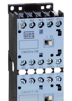
The CWC0 compact contactors are offered as a complete solution for switching and controlling motors.
 Compact Contactors The CWC compact contactors are offered as a complete solution for switching and controlling motors. Main Features Contactors with screw s for C-3 operation up to Contactors with spring
Automation Electronic Relays Modular Line
 Motors Automation Energy Transmission & Distribution Coatings Automation Electronic Relays Modular Line g Timing g Impulse Electronic Relays Line 17.5 mm Summary Application 06 Timing Relays 07 Time Setting
Motors Automation Energy Transmission & Distribution Coatings. Sync-Rite Plus System
 Motors Automation Energy Transmission & Distribution Coatings System System Features and Benefits The WEG Electric Machinery System integrates synchronization controls and rotor telemetry to provide the
TeSys contactors. TeSys D contactors. IEC/EN , IEC/EN , UL 508, CSA C22.2 n 14. Protection against direct fi nger contact IP 2X
 Characteristics Contactor type LC1 D09 D18 DT20 and DT25 Environment Rated insulation voltage (Ui) Conforming to IEC 097--1, overvoltage category III, degree of pollution: 3 Conforming to UL, CSA V 00
Characteristics 5 TeSys k contactors and reversing contactors
 90 Characteristics contactors k contactors and reversing contactors Environment characteristics Conforming to standards IEC 60947, NF C 63-110, VDE 0660, BS 424 Product certifications LCp and LPp K06 to
Type: DILM80(110V50HZ,120V60HZ) Article No.: Sales text Contactor,37kW/400V,AC operated. Ordering information
 Article No.: Sales text Contactor,37kW/400V,AC operated. Ordering information") Type: DILM80(110V50HZ,120V60HZ) Article No.: 239399 Sales text Contactor,37kW/400V,AC operated Ordering information Connection technique Description Description Rated operational current AC 3 380 V 400
Type: DILM80(110V50HZ,120V60HZ) Article No.: 239399 Sales text Contactor,37kW/400V,AC operated Ordering information Connection technique Description Description Rated operational current AC 3 380 V 400
Type: DILM95(230V50HZ,240V60HZ) Article No.: Sales text Contactor,45kW/400V,AC operated. Ordering information
 Article No.: Sales text Contactor,45kW/400V,AC operated. Ordering information") Type: DILM95(230V50HZ,240V60HZ) Article No.: 239480 Sales text Contactor,45kW/400V,AC operated Ordering information Connection technique Description Description Rated operational current AC 3 380 V 400
Type: DILM95(230V50HZ,240V60HZ) Article No.: 239480 Sales text Contactor,45kW/400V,AC operated Ordering information Connection technique Description Description Rated operational current AC 3 380 V 400
DATASHEET - ETR4-70-A. Delivery program. Timing relay, 2W, 0.05s-100h, multi-function, VAC/DC, potentiometer connection
 DATASHEET - ETR4-70-A Delivery program Timing relay, 2W, 0.05s-100h, multi-function, 24-240VAC/DC, potentiometer connection Part no. ETR4-70-A Catalog No. 031888 Eaton Catalog No. XTTR6A100H70B EL-Nummer
DATASHEET - ETR4-51-A. Delivery program. Technical data General. Timing relay, star-delta, 50 ms, 1W, 3-60s, VAC/DC
 DATASHEET - ETR4-51-A Timing relay, star-delta, 50 ms, 1W, 3-60s, 24-240VAC/DC Part no. ETR4-51-A Catalog No. 031884 Eaton Catalog No. XTTR6A60S51B EL-Nummer 0004133308 (Norway) Delivery program Product
Type: DILEM 10 G(24VDC) Article No.:
 Article No.:") Type: DILEM 10 G(24VDC) Article No.: 010213 Ordering information Description Connection technique Rated operational current AC 3 380 V 400 V I e A 9 Max. rating for three phase motors, 50 60 Hz AC 3 220
Type: DILEM 10 G(24VDC) Article No.: 010213 Ordering information Description Connection technique Rated operational current AC 3 380 V 400 V I e A 9 Max. rating for three phase motors, 50 60 Hz AC 3 220
Type: DILEM 10(220V50HZ,240V60HZ) Article No.:
 Article No.:") Type: DILEM 10(220V50HZ,240V60HZ) Article No.: 051785 Ordering information Actuating voltage Description Connection technique 380 V 400 V I e A 8.8 Max. rating for three phase motors, 50 AC 3 220 V 230
Type: DILEM 10(220V50HZ,240V60HZ) Article No.: 051785 Ordering information Actuating voltage Description Connection technique 380 V 400 V I e A 8.8 Max. rating for three phase motors, 50 AC 3 220 V 230
LC2D09BL REVERSING CONTACTOR 575VAC 9A IEC
 Product datasheet Characteristics LC2D09BL REVERSING CONTACTOR 575VAC 9A IEC Price* : 107.62 GBP Main Range Product name Product or component type Device short name Contactor application Utilisation category
Description Basic devices with positive operation contacts. Standards IEC/EN 60947, EN , VDE 0660, UL, CSA
 Contactor relay, 2N/O+2N/C, AC Part no. DILA-22(24V60HZ) Catalog No. 276390 Eaton Catalog No. XTRE10B22B6 Delivery program Product range DILA relays Application Contactor relays Description Basic devices
Controls Contactors and Contactor Assemblies Special Applications
 Controls Contactors and Contactor Assemblies Special Applications Price groups 1B, 1H /2 Introduction More information can be found on the Internet: see the opening information, page 13 - Contactors for
AC-3 AC-1 230V 400/415V 500V 690V 115V 230V 200V 230V 460V 575V N.O. N.C. Qty. Cat. No. Screw Terminals. Spring Clamp Terminals. 40 C Pkg.
 Bulletin -K, -K IEC Miniature Contactors Overview/Product Selection Product Selection -Pole AC- and DC-Operated Contactors Bulletin -K/-K IEC Miniature Contactors Compact size Same dimensions for AC and
Description Basic devices with positive operation contacts. Standards IEC/EN 60947, EN , VDE 0660, UL, CSA
 DATASHEET - DILA-22(230V50HZ,240V60HZ) Delivery program Contactor relay, 2N/O+2N/C, AC Part no. DILA-22(230V50HZ,240V60HZ) Catalog No. 276399 Eaton Catalog No. XTRE10B22F EL-Nummer 0004130208 (Norway)
Mini Contactors. Mini Contactor Relays 4-pole 8 Auxiliary Contact Blocks. Interface Contactor Relays. Mini Contactors 10 Auxiliary Contact Blocks
 Mini Contactors Mini Contactor Relays 4-pole 8 Auxiliary Contact Blocks Interface Contactor Relays Mini Contactors 10 Auxiliary Contact Blocks Mini Contactors With Fast On Tab Connectors 12 Mini Contactors
Micro Contactors. Micro Contactor Relays 10. Micro Contactors 11. Micro Contactors With Solder Pins 12. Coil voltages 12. Micro Reversing Contactor 13
 Micro Contactor Relays 10 Micro Contactors 11 Micro Contactors With Solder Pins 12 Coil voltages 12 Micro Reversing Contactor 13 Technical Data 14 Dimensions 18 D946E 9 Micro Contactor Relays 4-pole AC
LC1D25BL TeSys D contactor - 3P(3 NO) - AC-3 - <= 440 V 25 A - 24 V DC coil
 - AC-3 - <= 440 V 25 A - 24 V DC coil") Product data sheet Characteristics LC1D25BL TeSys D contactor - 3P(3 NO) - AC-3 -
Product data sheet Characteristics LC1D25BL TeSys D contactor - 3P(3 NO) - AC-3 -
LC2D09BD. Main. Device short name. Utilisation category. Poles description Pole contact composition
 Product datasheet Characteristics Main Range Product name Product or component type Device short name Contactor application Utilisation category Device presentation Poles description Pole contact composition
Instructions Contact numbers to EN Coil terminal markings to EN Integrated diode-resistor combination Coil rating 2.
 Delivery program Contactor relay, 2N/O+2N/C, DC current Part no. DILER-22-G(24VDC) Catalog No. 010042 Eaton Catalog No. XTRM10A22TD EL-Nummer 4130354 (Norway) Product range DILER Mini-contactors Application
PKZ 2 Manual Motor Protectors Technical Data
 08/066 PKZ 2 Manual Motor Protectors General Standards UL 508, CSA C 22.2 No. 14, IEC/EN 60 947, VDE 0660 GL, LR, DNV, PRS, BV, RINA, RS, EZU, MEEI Climatic proofing Damp heat, constant, to IEC 60 068-2-3
LC1D12BL TeSys D contactor - 3P(3 NO) - AC-3 - <= 440 V 12 A - 24 V DC coil
 - AC-3 - <= 440 V 12 A - 24 V DC coil") Characteristics TeSys D contactor - 3P(3 NO) - AC-3 -
Characteristics TeSys D contactor - 3P(3 NO) - AC-3 -
Description Basic devices with positive operation contacts. Connection to SmartWire-DT yes in conjunction with DIL-SWD SmartWire DT contactor module
 DATASHEET - DILA-22(24VDC) Delivery program Contactor relay, 2N/O+2N/C, DC current Part no. DILA-22(24VDC) Catalog No. 276414 Eaton Catalog No. XTRE10B22TD EL-Nummer 4130211 (Norway) Product range DILA
Description Basic devices with positive operation contacts
 Contactorrelay,3N/O+1N/C,DCcurrent Partno. DILA-31(24VDC) Articleno. 276379 CatalogNo. XTRE10B31TD Deliveryprogramme Product range DILA relays Application Contactor relays Description Basic devices with
Catalog 200 Contactors up to 115 A Motor Starters up to 55 kw 03/2009
 Catalog 00 Contactors up to 5 A Motor Starters up to 55 kw 03/009 Kraus & Naimer The development of the Blue Line rotary switch, contactor and motor starter product ranges is based on more than hundred
NS..S contactor relays - with spring terminals AC operated
 NS..S contactor relays - with spring terminals AC operated NSES 1SBC101015F00 Description NS..S contactor relays are used for switching auxiliary and control circuits. These contactor relays are designed
Add-on modules DX 3 63A for MCBs DX 3 1,5 modules per pole
 87045 LIMOGES Cedex Telephone number: +33 (0)5 55 06 87 87 Fax: +33 (0)5 55 06 88 88 Add-on modules DX 3 63A for MCBs CONTENTS PAGE 1. Description, use... 1 2. Range... 1 3. Overall dimensions... 1 4.
LC1D32BD TeSys D contactor - 3P(3 NO) - AC-3 - <= 440 V 32 A - 24 V DC coil
 - AC-3 - <= 440 V 32 A - 24 V DC coil") Characteristics TeSys D contactor - 3P(3 NO) - AC-3 -
Characteristics TeSys D contactor - 3P(3 NO) - AC-3 -
Utilization category DC-1 DC-3 DC-5 L/R 1 ms L/R 2 ms L/R 7.5 ms
 controls IEC Technical data D.C. Power circuit switching Utilization category DC- DC- DC- L/R ms L/R ms L/R 7. ms + + + V A 6.0 6.0 6.0 8 V A 6.0 8.0.0 60 V A 6.0.0. V A 7.0. 0. 0 V A 0.8 0. V A 6.0 6.0
AF AF V50/60HZ-DC Contactor. General Information. Ordering. Popular Downloads. Dimensions. Technical AF
 ABB AF12-30-01-14 250-500V50/60HZ-DC Contactor General Information Extended Product Type Product ID AF12-30-01-14 1SBL157001R1401 EAN 3471523110441 Catalog Description Long Description AF12-30-01-14 250-500V50/60HZ-DC
Type: DILM40(RDC24) Article No.:
 Article No.:") Type: DILM40(RDC24) Article No.: 277780 Ordering information Rated operational current AC 3 400 V I e A 40 Max. rating for three phase motors, 50 60 Hz AC 3 230 V Max. rating for three phase motors, 50
Type: DILM40(RDC24) Article No.: 277780 Ordering information Rated operational current AC 3 400 V I e A 40 Max. rating for three phase motors, 50 60 Hz AC 3 230 V Max. rating for three phase motors, 50
Electronic timer CT-MVS.23 Multifunctional with 2 c/o (SPDT) contacts
 contacts") Data sheet Electronic timer CT-MVS.23 Multifunctional with 2 c/o (SPDT) contacts The CT-MVS.23 is a multifunctional electronic timer from the CT-S range. It provides 11 timing functions and 10 time ranges.
Data sheet Electronic timer CT-MVS.23 Multifunctional with 2 c/o (SPDT) contacts The CT-MVS.23 is a multifunctional electronic timer from the CT-S range. It provides 11 timing functions and 10 time ranges.
Industrial Controls. Catalog IC SIRIUS. Answers for industry.
 Industrial Controls Catalog IC 10 2012 SIRIUS Answers for industry. Contactor Relays Siemens AG 2012 Overview Standards IEC 60947-1, EN 60947-1, IEC 60947--1, EN 60947--1 The 3TH42 and 3TH43 contactor
Motor-protective circuit-breaker, 3p, Ir=40-50A, screw connection. Product range PKZM4 motor protective circuit-breakers up to 65 A
 DATASHEET - PKZM4-50 Delivery program Motor-protective circuit-breaker, 3p, Ir=40-50A, screw connection Part no. PKZM4-50 Catalog No. 222355 Eaton Catalog No. XTPR050DC1NL EL-Nummer 0004355161 (Norway)
Modular equipment. Presentation, standards. Standard contactors TeSys GC
 Presentation, standards Standard contactors TeSys GC Presentation TeSys GC contactors are designed for use in modular panels and enclosures. These contactors feature: b Easy installation v quick clip-on
Electronic timer CT-SDE Star-delta change-over with 1 n/c + 1 n/o contact
 Data sheet Electronic timer CT-SDE Star-delta change-over with n/c + n/o contact The CT-SDE is an electronic time relay with star-delta change-over. It is from the CT-E range. The CT-E range is the economic
60 Series - General purpose relays 6-10 A. Features Plug-in mount 10 A General purpose relay
 Series - General purpose relays - 0 A Features Plug-in mount 0 A General purpose relay.. & pole changeover contacts Cadmium Free contacts (preferred version) AC coils & DC coils UL Listed (certain relay/socket
Motor starters. TeSys E. Designed for the essential
 Motor starters TeSys E Designed for the essential Designed for the essential Contents TeSys E contactors, 6 A to 300 A TeSys E thermal overload relays 0.1 A to 333 A TeSys E control relays 4 NO/NC contacts
Contactors and Contactor Assemblies
 s for Switching Motors Technical data General data Permissible mounting position The contactors are designed for operation on a vertical mounting surface. C and DC operation S3 3RT14 46 For DC operation
LC1D32ED TeSys D contactor - 3P(3 NO) - AC-3 - <= 440 V 32 A - 48 V DC coil
 - AC-3 - <= 440 V 32 A - 48 V DC coil") Product data sheet Characteristics LC1D32ED TeSys D contactor - 3P(3 NO) - AC-3 -
Product data sheet Characteristics LC1D32ED TeSys D contactor - 3P(3 NO) - AC-3 -
Artisan Technology Group is your source for quality new and certified-used/pre-owned equipment
 Artisan Technology Group is your source for quality new and certified-used/pre-owned equipment FAST SHIPPING AND DELIVERY TENS OF THOUSANDS OF IN-STOCK ITEMS EQUIPMENT DEMOS HUNDREDS OF MANUFACTURERS SUPPORTED
Output of three-phase motors at 50 Hz and 400 V
 RT0, RH Coupling Relays (Interfaces) Description DC operation IEC 0 947 and EN 0 947 (VDE 00) The RT0 coupling relays for switching motors and RH for auxiliary circuits are laid out to the special requirements
Electronic timer CT-SDS.22 Star-delta change-over with 2 n/o contacts Data sheet
 CDC 0 F0t07 Features Rated control supply voltage -8 V DC, -0 V AC Single-function timer with star-delta change-over One device includes 7 time ranges (0.0 s - 0 min) n/o contacts LEDs for status indication
Type: EASY719 DA RC Article No.: Ordering information Relay outputs Quantity 6 Power supply V DC 12 V DC. Description
 Type: EASY719 DA RC Article.: 274117 Ordering information Relay outputs Quantity 6 Power supply V DC 12 V DC Description 12 digital inputs (4 inputs available as analog inputs) 6 relay outputs LCD display
Capacitor Switching Contactors
 Capacitor Switching D385E51 Technical catalogues and news under: www.benedict.at Motor-Starter Mini- Overload Relays Capacitor Switching Motor-Starters Modular Circuit Breakers M4-32T... up to 32A M4-32R..
(1,5 modules per pole)
") 87045 LIMOGES Cedex Telephone: +33 5 55 06 87 87 FAX: +33 5 55 06 88 88 DX 3 MCB 25kA 80A to 125A CONTENTS PAGES 1. Description - Use... 1 2. Range... 1 3. Overall dimensions... 1 4. Preparation - Connection...
87045 LIMOGES Cedex Telephone: +33 5 55 06 87 87 FAX: +33 5 55 06 88 88 DX 3 MCB 25kA 80A to 125A CONTENTS PAGES 1. Description - Use... 1 2. Range... 1 3. Overall dimensions... 1 4. Preparation - Connection...
Type: EASY719 AC RC Article No.: Ordering information Relay outputs Quantity 6 Power supply V DC 115/230 V AC. Description
 Type: EASY719 AC RC Article No.: 274115 Ordering information Relay outputs Quantity 6 Power supply V DC 115/230 V AC Description 12 digital inputs 6 relay outputs LCD display Operating buttons Screw terminals
48 Series - Relay interface modules A. Features
 Series - Relay interface modules 8-0 - 6 A Features & Pole relay interface modules, 5.8 mm wide. Ideal interface for PLC and electronic systems.3 - Pole 0 A.5 - Pole 8 A.6 - Pole 6 A coils or sensitive
Electronic timer CT-AHS.22 OFF-delayed with 2 c/o (SPDT) contacts
 contacts") Data sheet Electronic timer CT-AHS.22 OFF-delayed with 2 c/o (SPDT) contacts The CT-AHS.22 is an electronic timer from the CT-S range with OFF-delay and 10 time ranges. All electronic timers from the CT-S
Data sheet Electronic timer CT-AHS.22 OFF-delayed with 2 c/o (SPDT) contacts The CT-AHS.22 is an electronic timer from the CT-S range with OFF-delay and 10 time ranges. All electronic timers from the CT-S
LC1D12BD TeSys D contactor - 3P(3 NO) - AC-3 - <= 440 V 12 A - 24 V DC coil
 - AC-3 - <= 440 V 12 A - 24 V DC coil") Product data sheet Characteristics LC1D12BD TeSys D contactor - 3P(3 NO) - AC-3 -
Product data sheet Characteristics LC1D12BD TeSys D contactor - 3P(3 NO) - AC-3 -
48 SERIES. Relay interface modules 8 A CO forcibly guided contacts relay interface modules,15.8 mm wide Type 48.12
 48 Relay interface modules 8 A 48 2 CO forcibly guided contacts relay interface modules,15.8 mm wide Type 48.12 2 CO 8 A s Relay with forcibly guided contacts according to EN 50205 Type 35 mm rail (EN
Electronic timer CT-WBS.22 Impulse generating and flashing with 2 c/o (SPDT) contacts
 contacts") Data sheet Electronic timer CT-WBS.22 Impulse generating and flashing with 2 c/o (SPDT) contacts The CT-WBS.22 is a multifunctional electronic timer from the CT-S range. It provides 10 timing functions
Data sheet Electronic timer CT-WBS.22 Impulse generating and flashing with 2 c/o (SPDT) contacts The CT-WBS.22 is a multifunctional electronic timer from the CT-S range. It provides 10 timing functions
Electronic timer CT-SDS.22
 CDC 0 F0t07 Features Rated control supply voltage 8 V DC, 0 V AC Single function timer with star delta change over One device includes 7 time ranges (0.0 s 0 min) n/o contacts LEDs for status indication
38 Series - Relay interface modules A. Features /
 Series - Relay interface modules 0.1-2 - 6-8 A Features 1 Pole - 6 A electromechanical relay interface modules, 6.2 mm wide. Ideal interface for PLC and electronic systems Sensitive DC coil or coil versions
Electronic timer CT-TGD.12 Pulse generator with 1 c/o (SPDT) contact
 contact") Data sheet Electronic timer CT-TGD.12 Pulse generator with 1 c/o (SPDT) contact The CT-TGD.12 is an electronic time relay with the function pulse generator. It is from the CT-D range. With their MDRC profile
Data sheet Electronic timer CT-TGD.12 Pulse generator with 1 c/o (SPDT) contact The CT-TGD.12 is an electronic time relay with the function pulse generator. It is from the CT-D range. With their MDRC profile
Three-phase monitoring relays CM-PFE and CM-PFE.2
 Data sheet Three-phase monitoring relays CM-PFE and CM-PFE.2 The CM-PFE is a three-phase monitoring relay that monitors the phase parameter phase sequence and phase failure in three-phase mains. 2CDC 251
58 SERIES. Relay interface modules 7-10 A 58.P3 58.P4
 58 58 3 & 4 CO relay interface modules, 31 mm wide with Push-in terminals Ideal interface for PLC and electronic systems 58.P3 58.P4 Type 58.P3 3 CO 10 A Push-in terminals Type 58.P4 4 CO 7 A Push-in terminals
XT IEC Power Control Miniature Controls
 Product Family Overview May 07 Contents Description Page Selection................ Product Selection.......... Non-reversing Mini Contactors......... Reversing Mini Contactors............. Star-Delta (Wye-Delta)
Electronic timer CT-EBE Flasher starting with OFF, 1 c/o (SPDT) contact
 contact") Data sheet Electronic timer CT-EBE Flasher starting with OFF, 1 c/o (SPDT) contact The CT-EBE is an electronic time relay with the function flasher starting with OFF. It is from the CT-E range. The CT-E
Data sheet Electronic timer CT-EBE Flasher starting with OFF, 1 c/o (SPDT) contact The CT-EBE is an electronic time relay with the function flasher starting with OFF. It is from the CT-E range. The CT-E
Approved Standards. Ordering Information. Mini Contactor Relays 4-pole J7KNA-AR. Model Number Legend. Main contactor. Accessories
 Mini Contactor Relays 4-pole J7KN-R ) Main contactor C & DC operated 4-, 6- and 8-pole versions in different configurations Mirror contacts Screw fixing and snap fitting (35 mm DIN rail) Rated current
Voltage monitoring relay CM-EFS.2 For single-phase AC/DC voltages
 Data sheet Voltage monitoring relay CM-EFS.2 For single-phase AC/DC voltages The CM-EFS.2 is an electronic voltage monitoring relay that provides reliable monitoring of voltages as well as detection of
RE7MY13MW time delay relay 8 functions s V AC DC - 2OC
 Characteristics time delay relay 8 functions - 0.05..1 s - 240 V AC DC - 2OC Main Range of product Product or component type Contacts type and composition Component name Time delay type Time delay range
Current monitoring relays CM-SRS.2 for single-phase AC/DC currents
 Data sheet Current monitoring relays CM-SRS.2 for single-phase AC/DC currents For the monitoring of currents in single-phase AC/DC systems, ABB s CM range comprises a wide selection of powerful and compact
Current monitoring relays CM-SRS.M1 For single-phase AC/DC currents
 Data sheet Current monitoring relays CM-SRS.M1 For single-phase AC/DC currents The CM-SRS.M1 is an electronic current monitoring relay that monitors single-phase mains (DC or AC) for over- and undercurrent
References 1 for asynchronous motors 1
 References 1 DF56902 DF5690 DF56901 ATS 01N10FT ATS 01N212QN ATS 01N20LY for 0.7 to kw motors power Nominal current Reference (2) Weight Single phase -phase 20 V 210 V 20 V 20 V 400 V 460 V kw HP kw HP
Voltage monitoring relays CM-ESS.M For single-phase AC/DC voltages
 Data sheet Voltage monitoring relays CM-ESS.M For single-phase AC/DC voltages The CM-ESS.M is an electronic voltage monitoring relay that provides reliable monitoring of voltages as well as detection of
ATS01N112FT soft starter for asynchronous motor - ATS01-12 A V KW
 Characteristics soft starter for asynchronous motor - ATS01-12 A - 110..480V - 1.5..5.5 KW Main Range of product Altistart 01 Product or component type Product destination Product specific application
Voltage monitoring relays CM-ESS.1 for single-phase AC/DC voltages
 Data sheet Voltage monitoring relays CM-ESS.1 for single-phase AC/DC voltages For the monitoring of voltages in single-phase AC/DC systems, ABB s CM range comprises a wide selection of powerful and compact
ATS01N125FT soft starter for asynchronous motor - ATS01-25 A V KW
 Characteristics soft starter for asynchronous motor - ATS01-25 A - 110..480V - 2.2..11 KW Main Range of product Altistart 01 Product or component type Product destination Product specific application Device
Power supply CP-D 24/4.2 Primary switch mode power supply
 Data sheet Power supply CP-D 24/4.2 Primary switch mode power supply The CP-D range of modular power supply units in MDRC design (modular DIN rail components) is ideally suited for installation in distribution
Relays & Sockets. RF1V Force Guided Relays/SF1V Relay Sockets. Certification Organization/ File Number. UL/c-UL File No.
 RFV Key features: Compact and EN compliant RFV force guided relays Force guided contact mechanism (EN00 Type A TÜV approved) Contact configuration -pole (NO-NC, 3NO-NC) 6-pole (NO-NC, NO-NC, 3NO-3NC) Built-in
Index. Capacitor Switching - 2 Contactors. Typical Circuit Diagram 2. Auxiliary Contact Blocks 2. Contactors 3. Dimensions 3. Technical Data 4,5,6
 Index Index Page Capacitor Switching - 2 Contactors Typical Circuit Diagram 2 Auxiliary Contact Blocks 2 Contactors 3 Dimensions 3 Technical Data 4,5,6 Contactor operation 7 Function 8 Construction 9 Oscillogram
s s s 3-60 s min min 3-60 min h h 3-60 h V AC, 50/60 Hz
 HPL11002EN DILETTiming relays Rated operational current AC-11 230 V 400 V I th I e I e A A A A A Conventional thermal current Time Range Voltage Article No. See price list Std. pack On-delayed Timing functions
Block Contactors. Contents. Panorama 3-pole Contactors... 2/2 4-pole Contactors... 2/4
 /0 Block Contactors Contents Panorama -pole Contactors... / 4-pole Contactors... /4 -pole Contactors: Description and Ordering Details A 9... A 0 Contactors (a.c. Operated)... /6 A 4... AF 60 Contactors
Current monitoring relays CM-SRS.1 For single-phase AC/DC currents
 Data sheet Current monitoring relays CM-SRS.1 For single-phase AC/DC currents The CM-SRS.1 is an electronic current monitoring relay that protects single-phase mains (DC or AC) from over- and undercurrent
3RF A A 0 2. Switching function. Control voltage Operating voltage with heat sink 10 = 10.5 A. A = Zero-point switching
 Main Characteristics: Zero-point switching LED display Various connection technologies Plug-in control terminal Degree of protection IP 2 Insulated mounting foot Standards / Approvals: DIN EN 697--3 UL
40 Series - Miniature P.C.B. Relays A
 ..4..4..4 40 Series - Miniature P.C.B. Relays 8-0 - 6 A - P.C.B. or plug-in mount - AC, DC, sensitive DC or single bistable coil versions available - 8 mm, 6 kv (./0 µs) between coil and contacts - Ambient
Measuring and monitoring relays CM-SRS.1 Current monitoring relays, single-phase AC/DC
 2CDC 251 244 F0t05 Characteristics Monitoring of DC and AC currents: RMS measuring principle One device includes 3 measuring ranges Over- or undercurrent monitoring configurable Hysteresis adjustable from
Technical features table for miniature circuit-breakers SH 200 Series
 Technical features table for miniature circuit-breakers SH 00 Series Standards Poles Tripping characteristics I n A frequency f Hz insulation voltage U i acc. to IEC/EN 60664-1 V Overvoltage category Pollution
Control relays. K mini-control relays. 2 or 4 for CA2-K and CA3-K: 2 for CA4-K. Conforming to VDE 0110 group C V 750
 Characteristics Contact characteristics of mini-control relays and instantaneous contact blocks Number of contacts On CAp-K 4 On L-K 2 or 4 for C-K and CA3-K: 2 for CA4-K Rated operational voltage (Ue)
Electronic timer CT-AHS.22 OFF-delayed with 2 c/o (SPDT) contacts
 contacts") Data sheet Electronic timer CT-AHS.22 OFF-delayed with 2 c/o (SPDT) contacts The CT-AHS.22 is an electronic timer from the CT-S range with true OFF-delay and 10 time ranges. All electronic timers from
Data sheet Electronic timer CT-AHS.22 OFF-delayed with 2 c/o (SPDT) contacts The CT-AHS.22 is an electronic timer from the CT-S range with true OFF-delay and 10 time ranges. All electronic timers from
Electronic timer CT-MFS.21
 2CDC 251 053 F0t07 a Rotary switch for the preselection of the time range b Potentiometer with direct reading scale for the fine adjustment of the time delay c Rotary switch for the preselection of the
Page 13-2 Page Page 13-7
 Page -2 Page -6 MINIATURE CIRCUIT BREAKERS UP TO 63A 1P, 1P+N, 2P, 3P and 4P versions IEC rated current In: 1-63A IEC short-circuit capacity Icn: 10kA (6kA for 1P+N) Trip characteristic curve: Type B,
RJ Series Slim Power Relays
 RJ Series RJ Series Slim Relays Circuit Breakers Terminal Blocks Timers Display Lights Switches & Pilot Lights Compact and rugged power relays. Large switching capacity. Compact housing only.7-mm wide.
Current monitoring relays CM-SRS.2 For single-phase AC/DC currents
 Data sheet Current monitoring relays CM-SRS.2 For single-phase AC/DC currents The CM-SRS.2 is an electronic current monitoring relay that protects single-phase mains (DC or AC) from over- and undercurrent
38 Series - Relay Interface Modules A
 Series - Relay Interface Modules 0.1-2 - 6 A - Relay interface modules for use with PLC systems, mm wide - Sensitive DC coil or AC/DC coil version - Supplied with integral coil - Instant removal of relay
Relay interface modules A
 4C SЕRIES Relay interface modules 8-10 - 16 A Escalators Road / tunnel lighting Hoists and cranes Carousel warehouses Control panels Panels for electrical distribution FINDER reserves the right to alter
Electronic timer CT-YDE Star-delta change-over with 1 c/o (SPDT) contact
 contact") Data sheet Electronic timer CT-YDE Star-delta change-over with c/o (SPDT) contact The CT-YDE is an electronic time relay with star-delta change-over. It is from the CT-E range. The CT-E range is the economic
Data sheet Electronic timer CT-YDE Star-delta change-over with c/o (SPDT) contact The CT-YDE is an electronic time relay with star-delta change-over. It is from the CT-E range. The CT-E range is the economic
Electronic timer CT-SDD.22
 CDC 099 F0t0 a Rotary switch for the preselection of the time range b Potentiometer with direct reading scale for the fine adjustment of the time delay c U: green LED V control supply voltage applied W
Current monitoring relays CM-SRS.1 for single-phase AC/DC currents
 Data sheet Current monitoring relays CM-SRS.1 for single-phase AC/DC currents For the monitoring of currents in single-phase AC/DC systems, ABB s CM range comprises a wide selection of powerful and compact
Bulletin 100S-C/104S-C Safety Contactors. Bulletin 700S-CF Safety Control Relays. Table of Contents. Selection Guide
 Bulletin S-C/S-C Safety Contactors Bulletin 7S-CF Safety Control Relays Selection Guide Table of Contents Description Page Bulletin S-C/S-C Safety Contactors Product Selection.................................
Voltage monitoring relays CM-ESS.2 For single-phase AC/DC voltages
 Data sheet Voltage monitoring relays CM-ESS.2 For single-phase AC/DC voltages The CM-ESS.2 is an electronic voltage monitoring relay that provides reliable monitoring of voltages as well as detection of
62 Series - Power relays 16 A. Features / /
 6 Series - Power relays 6 A Features 6. / 6.3 6.-0300 / 6.3-0300 Printed circuit mount 6 A Power relay & 3 Pole changeover contacts or NO ( 3 mm contact gap) AC coils & DC coils Reinforced insulation between
Electronic timer CT-MXS.22 Multifunctional with 2 c/o (SPDT) contacts
 contacts") Data sheet Electronic timer CT-MXS.22 Multifunctional with 2 c/o (SPDT) contacts The CT-MXS.22 is a multifunctional electronic timer from the CT-S range. It provides 5 timing functions, 2 times 10 time
Data sheet Electronic timer CT-MXS.22 Multifunctional with 2 c/o (SPDT) contacts The CT-MXS.22 is a multifunctional electronic timer from the CT-S range. It provides 5 timing functions, 2 times 10 time
38 Series - Relay interface modules A
 38 Series - Relay interface modules 0.1-2 - 3-5 - 6-8 A Common features Instant ejection of relay by plastic retaining clip Integral coil indication and protection circuit EMR Electromechanical Relays
Electronic timer CT-MBS.22 Multifunctional with 2 c/o (SPDT) contacts
 contacts") Data sheet Electronic timer CT-MBS.22 Multifunctional with 2 c/o (SPDT) contacts The CT-MBS.22 is a multifunctional electronic timer from the CT-S range. It provides 10 timing functions and 10 time ranges.
Data sheet Electronic timer CT-MBS.22 Multifunctional with 2 c/o (SPDT) contacts The CT-MBS.22 is a multifunctional electronic timer from the CT-S range. It provides 10 timing functions and 10 time ranges.
38 Series - Relay interface modules A
 38 Series - Relay interface modules 0.1-2 - 3-5 - 6-8 A Common features Instant ejection of relay by plastic retaining clip Integral coil indication and protection circuit 6.2 mm wide EMR - DC, AC or AC/DC
New Products Catalogue 2009 Safety Relays ESR5
 www.moeller.net New Products Catalogue 2009 Safety Relays ESR5 u Description Functional safety on machines monitoring with safety relays ESR5 Emergency-stop circuits Monitoring of movable guards with guard
2 Pole CO, 8 A Plug-in 2 CO (DPDT) 1 CO (SPDT) 8/15 16/25* 250/ /400 2,000 4, /0.5/ /0.5/ (5/5) 300 (10/5)
 1 CO (SPDT) 8/15 16/25* 250/ /400 2,000 4, /0.5/ /0.5/ (5/5) 300 (10/5)") 46 Series - Relays for railway applications 8-16 A 46 SERIES Features Plug-in power relays: 8 A, 2 pole 16 A, 1 pole Complies with EN 45545-2:2013 (protection against fire of materials), EN 61373 (resistance
46 Series - Relays for railway applications 8-16 A 46 SERIES Features Plug-in power relays: 8 A, 2 pole 16 A, 1 pole Complies with EN 45545-2:2013 (protection against fire of materials), EN 61373 (resistance