Telescopes and their configurations. Quick review at the GO level
|
|
|
- Silvester Brian Melton
- 6 years ago
- Views:
Transcription
1 Telescopes and their configurations Quick review at the GO level


2 Refraction & Reflection Light travels slower in denser material Speed depends on wavelength
 virtual real virtual A real image can be projected onto a screen, film or")
3 Image Formation real Focal Length (f) : Distance from lens to focus Focal Ratio (f/#) : f / lens diameter (D) virtual real virtual A real image can be projected onto a screen, film or detector

4 Galileo Telescope Strong lens Weak lens Long focal length This telescope makes a magnified virtual image Retina: detector array of 25 million photoreceptors
5 Galileo Telescope Strong lens Weak lens Long focal length This telescope makes a magnified virtual image Where would the detector go?

6 Kepler telescope Telescope evolution

7 Lick 1-meter telescope Why so long?
8 Problems with lenses?

9 Reflecting Telescopes Who came up with this idea?

10 Telescopes with long focal lengths in a shorter telescope LBT, Magellan, VATT, Giant Magellan Cassegrain Parabolic primary and ellipsoid secondary Parabolic/hyperbolic primary and hyperbolic secondary Gemini

11 Focii Primary Cassegrain Nasmyth
12 What are the advantages of each of these focii?


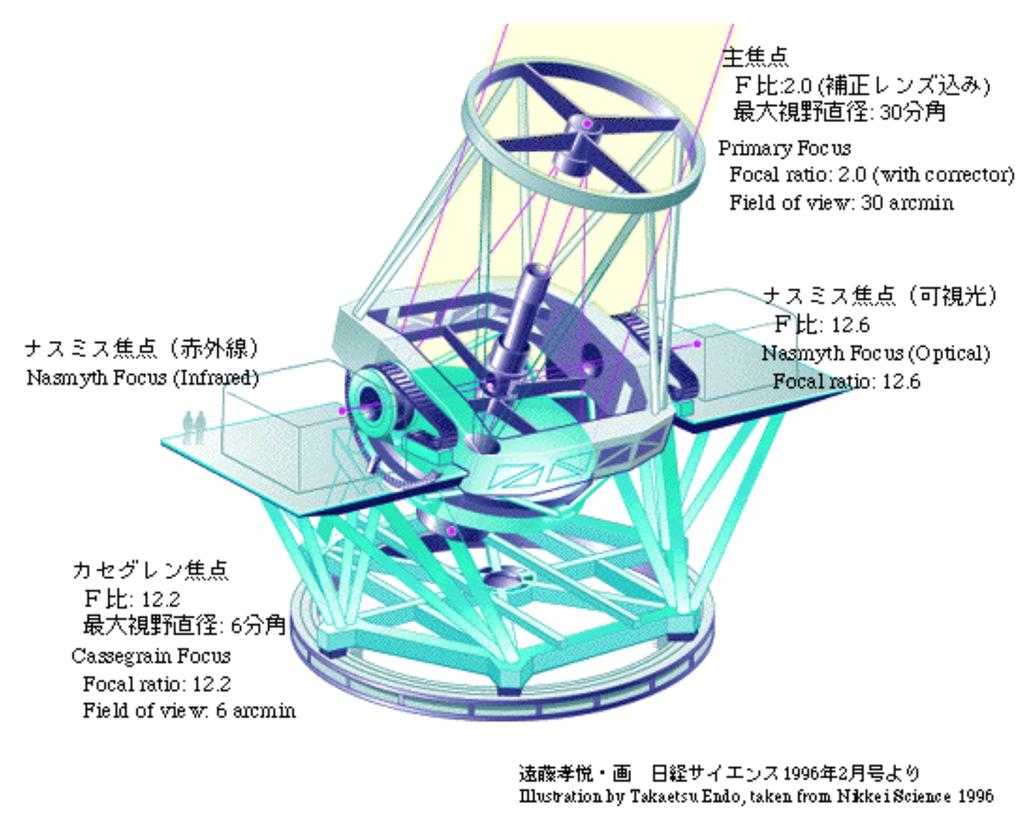
13 Examples Nasmyth Subaru f/2, f/12.2, f/12.6 LBT
14


15 Mounts one rotational axis parallel to the Earth's axis of rotation equatorial Alt-azimuth
16 Angular Magnification For look through telescopes
17 For a Detector Array Put the detector at the focus (orange) and consider the angle that subtends 1 mm For a telescope where there is no eye piece the angular magnification is specified by the Image scale or plate scale, θ: the number of arcseconds imaged onto 1 mm of the detector
18 Field of View Field of view depends on the linear scale, L, of the detector The larger the focal length the larger the angular magnification The smaller the focal length the larger the field of view.
19 Summary The configuration of the telescope determines the angular magnification, the field of view, the amount of light gathered, and the mounting possibilities for the instruments Next section: diffraction


20 Diffraction 1803, Thomas Young: Light behaves like waves
21 Interference Young s sketch to Royal Society (1803) What happened in 1961 and 1974?
22 What happens if you use electrons instead of photons?
23 What happens when you fire electrons at the 2 slits one at a time?

24 Jonsson at Tubingen: eform defraction patterns (1961) Merli at Bologna: e- one at a time make defraction patterns (1974)
 But if you measure which slit the e- go through -> no diffraction")
25 Interference Young s sketch to Royal Society (1803) Jonsson at Tubingen: e- form defraction patterns (1961) Merli at Bologna: e- one at a time make defraction patterns (1974) But if you measure which slit the e- go through -> no diffraction pattern
26 Diffraction Limit limiting angular separation of two point sources in the sky
27 Question What is the size of the pixels that we need to resolve a diffraction limited image on the detector which sits at the focal plane?
28 Question What is the size of the pixels that we need to resolve a diffraction limited image on the detector which sits at the focal plane? θ=x/f Diffraction limit angle Angular extent of a pixel size x
29 Diffraction Limit The f-stop = f/# = f/d The focal length/lens diameter Considering the viewing of a uniformly lit field, the brightness of the projected image (illuminance) relative to the brightness of the scene in the lens's field of view (luminance) decreases with the square of the f-number Tells you the optimal pixel size for a telescope, which depends on D and f (f/#) and wavelength range.
30 Diffraction Limit My new Nikon 300 Middle f-stop: f/8 Pixel size of CCD is 5.3 um Is this consistent with the optics Consider our eyes Middle f-stop: f/5 Max density of cones 70,000/mm 2 Spacing is 2.5 um Is this a reasonable design? Tells you the optimal pixel size for a telescope, which depends on D and f (f/#) and wavelength range.
31 Diffraction Limit Tells you the optimal pixel size for a telescope, which depends on D and f (f/#) and wavelength range. For my Nikon 300 Middle f-stop: f/8 X = 1.22 * 8 * 0.42 um = 4.1 um Real pixel size is 5.3 um! Not bad For our eyes Middle f-stop: f/5 X = 1.22 * 5.7 * 0.42 um = 2.9 um Max density of cones 70,000/mm 2 Spacing is 2.5 um Nice design!
32 Atmospheric effects

33 Atmospheric Effects Seeing FWHM of optical image of a point source The Strehl ratio: the ratio of the peak aberrated image intensity from a point source compared to the maximum attainable intensity using an ideal optical system limited only by diffraction over the system's aperture. Alternatively one uses not of the peak intensity but the intensity at the image center (intersection of the optical axis with the focal plane) due to an on-axis source


34 Point spread function: Rayeigh s criterion Angular Resolution degraded by atmospheric turbulence to arcsecs (called seeing )
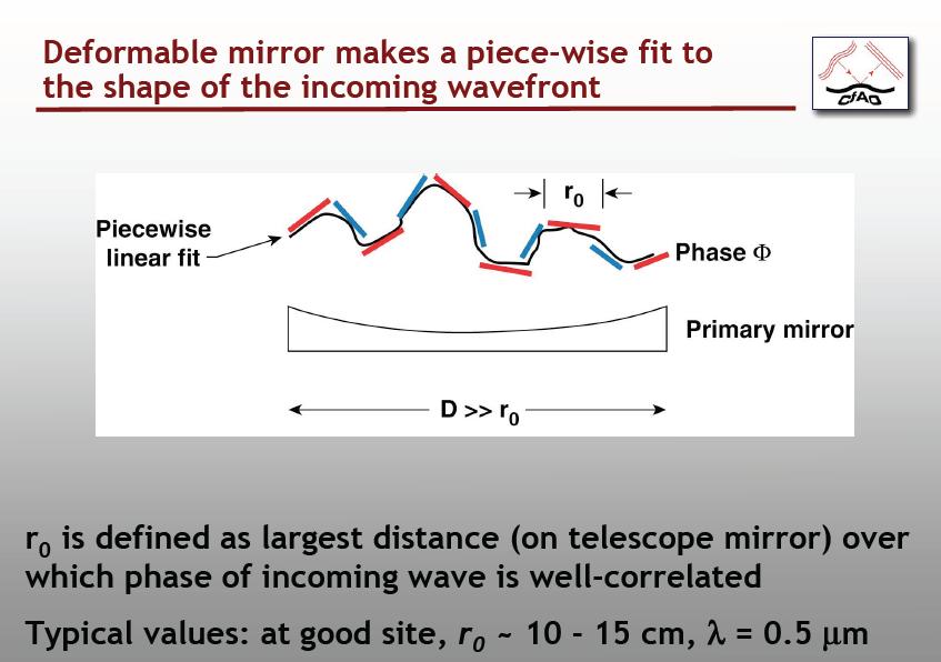
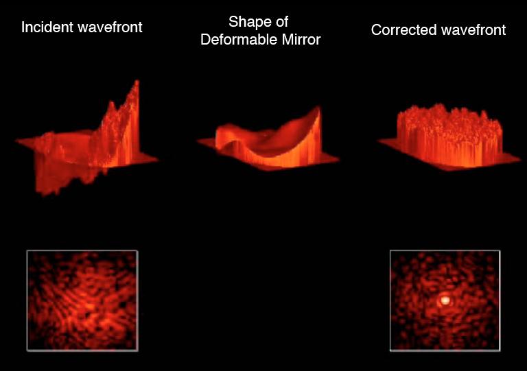
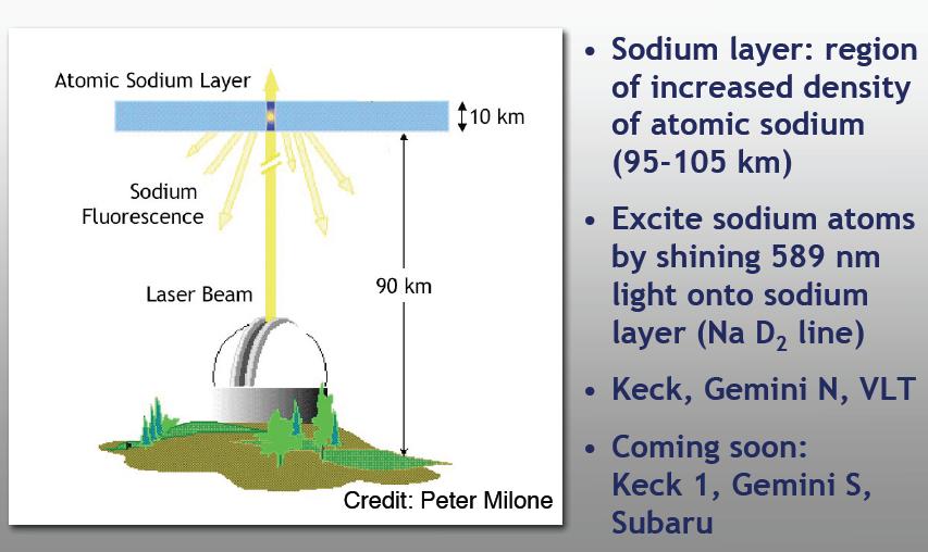
35 Adaptive Optics Object & Guide star AO slides from Claire Max

36
37
38
39
40

41 Note PSF varies with time
42 Summary Telescope configurations define some observational limitations The diameter establishes: the diffration-limit spatial resolution the light bucket size The focal length affects the angular magnification the photon flux in the detector combined w. array size gives FOV The focal number indicates the power of the lens The mount can affect time-sequenced observations AO capabilities increases spatial resolution in IR measurements mess up photometric measurements (variable PSF)
43 Telescopes

44 Field of View L/2 Field of view depends on the linear scale, L, of the detector

45 Adaptive Optics Object & Guide star AO slides from Claire Max
Early Telescopes & Geometrical Optics. C. A. Griffith, Class Notes, PTYS 521, 2016 Not for distribution.
 Early Telescopes & Geometrical Optics C. A. Griffith, Class Notes, PTYS 521, 2016 Not for distribution. 1 1.2. Image Formation Fig. 1. Snell s law indicates the bending of light at the interface of two
Reflectors vs. Refractors
 1 Telescope Types - Telescopes collect and concentrate light (which can then be magnified, dispersed as a spectrum, etc). - In the end it is the collecting area that counts. - There are two primary telescope
Applications of Optics
 Nicholas J. Giordano www.cengage.com/physics/giordano Chapter 26 Applications of Optics Marilyn Akins, PhD Broome Community College Applications of Optics Many devices are based on the principles of optics
There is a range of distances over which objects will be in focus; this is called the depth of field of the lens. Objects closer or farther are
 Chapter 25 Optical Instruments Some Topics in Chapter 25 Cameras The Human Eye; Corrective Lenses Magnifying Glass Telescopes Compound Microscope Aberrations of Lenses and Mirrors Limits of Resolution
Two Fundamental Properties of a Telescope
 Two Fundamental Properties of a Telescope 1. Angular Resolution smallest angle which can be seen = 1.22 / D 2. Light-Collecting Area The telescope is a photon bucket A = (D/2)2 D A Parts of the Human Eye
Chapter 34 The Wave Nature of Light; Interference. Copyright 2009 Pearson Education, Inc.
 Chapter 34 The Wave Nature of Light; Interference 34-7 Luminous Intensity The intensity of light as perceived depends not only on the actual intensity but also on the sensitivity of the eye at different
PHYSICS. Chapter 35 Lecture FOR SCIENTISTS AND ENGINEERS A STRATEGIC APPROACH 4/E RANDALL D. KNIGHT
 PHYSICS FOR SCIENTISTS AND ENGINEERS A STRATEGIC APPROACH 4/E Chapter 35 Lecture RANDALL D. KNIGHT Chapter 35 Optical Instruments IN THIS CHAPTER, you will learn about some common optical instruments and
The Imaging Chain in Optical Astronomy
 The Imaging Chain in Optical Astronomy Review and Overview Imaging Chain includes these elements: 1. energy source 2. object 3. collector 4. detector (or sensor) 5. processor 6. display 7. analysis 8.
The Imaging Chain in Optical Astronomy
 The Imaging Chain in Optical Astronomy 1 Review and Overview Imaging Chain includes these elements: 1. energy source 2. object 3. collector 4. detector (or sensor) 5. processor 6. display 7. analysis 8.
Chapter 25. Optical Instruments
 Chapter 25 Optical Instruments Optical Instruments Analysis generally involves the laws of reflection and refraction Analysis uses the procedures of geometric optics To explain certain phenomena, the wave
Binocular and Scope Performance 57. Diffraction Effects
 Binocular and Scope Performance 57 Diffraction Effects The resolving power of a perfect optical system is determined by diffraction that results from the wave nature of light. An infinitely distant point
INTRODUCTION THIN LENSES. Introduction. given by the paraxial refraction equation derived last lecture: Thin lenses (19.1) = 1. Double-lens systems
 = 1. Double-lens systems") Chapter 9 OPTICAL INSTRUMENTS Introduction Thin lenses Double-lens systems Aberrations Camera Human eye Compound microscope Summary INTRODUCTION Knowledge of geometrical optics, diffraction and interference,
Chapter 9 OPTICAL INSTRUMENTS Introduction Thin lenses Double-lens systems Aberrations Camera Human eye Compound microscope Summary INTRODUCTION Knowledge of geometrical optics, diffraction and interference,
Scaling relations for telescopes, spectrographs, and reimaging instruments
 Scaling relations for telescopes, spectrographs, and reimaging instruments Benjamin Weiner Steward Observatory University of Arizona bjw @ asarizonaedu 19 September 2008 1 Introduction To make modern astronomical
PHYS 160 Astronomy. When analyzing light s behavior in a mirror or lens, it is helpful to use a technique called ray tracing.
 Optics Introduction In this lab, we will be exploring several properties of light including diffraction, reflection, geometric optics, and interference. There are two sections to this lab and they may
PHY 431 Homework Set #5 Due Nov. 20 at the start of class
 PHY 431 Homework Set #5 Due Nov. 0 at the start of class 1) Newton s rings (10%) The radius of curvature of the convex surface of a plano-convex lens is 30 cm. The lens is placed with its convex side down
25 cm. 60 cm. 50 cm. 40 cm.
 Geometrical Optics 7. The image formed by a plane mirror is: (a) Real. (b) Virtual. (c) Erect and of equal size. (d) Laterally inverted. (e) B, c, and d. (f) A, b and c. 8. A real image is that: (a) Which
Phys 2310 Mon. Oct. 16, 2017 Today s Topics. Finish Chapter 34: Geometric Optics Homework this Week
 Phys 2310 Mon. Oct. 16, 2017 Today s Topics Finish Chapter 34: Geometric Optics Homework this Week 1 Homework this Week (HW #10) Homework this week due Mon., Oct. 23: Chapter 34: #47, 57, 59, 60, 61, 62,
Imaging Instruments (part I)
") Imaging Instruments (part I) Principal Planes and Focal Lengths (Effective, Back, Front) Multi-element systems Pupils & Windows; Apertures & Stops the Numerical Aperture and f/# Single-Lens Camera Human
Imaging Instruments (part I) Principal Planes and Focal Lengths (Effective, Back, Front) Multi-element systems Pupils & Windows; Apertures & Stops the Numerical Aperture and f/# Single-Lens Camera Human
Physics 1C. Lecture 25B
 Physics 1C Lecture 25B "More than 50 years ago, Austrian researcher Ivo Kohler gave people goggles thats severely distorted their vision: The lenses turned the world upside down. After several weeks, subjects
Observational Astronomy
 Observational Astronomy Instruments The telescope- instruments combination forms a tightly coupled system: Telescope = collecting photons and forming an image Instruments = registering and analyzing the
Gemini 8m Telescopes Instrument Science Requirements. R. McGonegal Controls Group. January 27, 1996
 GEMINI 8-M Telescopes Project Gemini 8m Telescopes Instrument Science Requirements R. McGonegal Controls Group January 27, 1996 GEMINI PROJECT OFFICE 950 N. Cherry Ave. Tucson, Arizona 85719 Phone: (520)
Chapter 3 Optical Systems
 Chapter 3 Optical Systems The Human Eye [Reading Assignment, Hecht 5.7.1-5.7.3; see also Smith Chapter 5] retina aqueous vitreous fovea-macula cornea lens blind spot optic nerve iris cornea f b aqueous
Light gathering Power: Magnification with eyepiece:
 Telescopes Light gathering Power: The amount of light that can be gathered by a telescope in a given amount of time: t 1 /t 2 = (D 2 /D 1 ) 2 The larger the diameter the smaller the amount of time. If
Big League Cryogenics and Vacuum The LHC at CERN
 Big League Cryogenics and Vacuum The LHC at CERN A typical astronomical instrument must maintain about one cubic meter at a pressure of
Chapter 25 Optical Instruments
 Chapter 25 Optical Instruments Units of Chapter 25 Cameras, Film, and Digital The Human Eye; Corrective Lenses Magnifying Glass Telescopes Compound Microscope Aberrations of Lenses and Mirrors Limits of
Image Formation. Light from distant things. Geometrical optics. Pinhole camera. Chapter 36
 Light from distant things Chapter 36 We learn about a distant thing from the light it generates or redirects. The lenses in our eyes create images of objects our brains can process. This chapter concerns
Option G 4:Diffraction
 Name: Date: Option G 4:Diffraction 1. This question is about optical resolution. The two point sources shown in the diagram below (not to scale) emit light of the same frequency. The light is incident
VC 11/12 T2 Image Formation
 VC 11/12 T2 Image Formation Mestrado em Ciência de Computadores Mestrado Integrado em Engenharia de Redes e Sistemas Informáticos Miguel Tavares Coimbra Outline Computer Vision? The Human Visual System
Geometrical Optics for AO Claire Max UC Santa Cruz CfAO 2009 Summer School
 Geometrical Optics for AO Claire Max UC Santa Cruz CfAO 2009 Summer School Page 1 Some tools for active learning In-class conceptual questions will aim to engage you in more active learning and provide
Vision. The eye. Image formation. Eye defects & corrective lenses. Visual acuity. Colour vision. Lecture 3.5
 Lecture 3.5 Vision The eye Image formation Eye defects & corrective lenses Visual acuity Colour vision Vision http://www.wired.com/wiredscience/2009/04/schizoillusion/ Perception of light--- eye-brain
VC 14/15 TP2 Image Formation
 VC 14/15 TP2 Image Formation Mestrado em Ciência de Computadores Mestrado Integrado em Engenharia de Redes e Sistemas Informáticos Miguel Tavares Coimbra Outline Computer Vision? The Human Visual System
12.4 Alignment and Manufacturing Tolerances for Segmented Telescopes
 330 Chapter 12 12.4 Alignment and Manufacturing Tolerances for Segmented Telescopes Similar to the JWST, the next-generation large-aperture space telescope for optical and UV astronomy has a segmented
Improving the Detection of Near Earth Objects for Ground Based Telescopes
 Improving the Detection of Near Earth Objects for Ground Based Telescopes Anthony O'Dell Captain, United States Air Force Air Force Research Laboratories ABSTRACT Congress has mandated the detection of
ECEN 4606, UNDERGRADUATE OPTICS LAB
 ECEN 4606, UNDERGRADUATE OPTICS LAB Lab 2: Imaging 1 the Telescope Original Version: Prof. McLeod SUMMARY: In this lab you will become familiar with the use of one or more lenses to create images of distant
12:40-2:40 3:00-4:00 PM
 Physics 294H l Professor: Joey Huston l email:huston@msu.edu l office: BPS3230 l Homework will be with Mastering Physics (and an average of 1 hand-written problem per week) Help-room hours: 12:40-2:40
Lecture 8. Lecture 8. r 1
 Lecture 8 Achromat Design Design starts with desired Next choose your glass materials, i.e. Find P D P D, then get f D P D K K Choose radii (still some freedom left in choice of radii for minimization
Refraction is the when a ray changes mediums. Examples of mediums:
 Refraction and Lenses Refraction is the when a ray changes mediums. Examples of mediums: Lenses are optical devices which take advantage of the refraction of light to 1. produces images real and 2. change
Section A Conceptual and application type questions. 1 Which is more observable diffraction of light or sound? Justify. (1)
") INDIAN SCHOOL MUSCAT Department of Physics Class : XII Physics Worksheet - 6 (2017-2018) Chapter 9 and 10 : Ray Optics and wave Optics Section A Conceptual and application type questions 1 Which is more
INDIAN SCHOOL MUSCAT Department of Physics Class : XII Physics Worksheet - 6 (2017-2018) Chapter 9 and 10 : Ray Optics and wave Optics Section A Conceptual and application type questions 1 Which is more
VC 16/17 TP2 Image Formation
 VC 16/17 TP2 Image Formation Mestrado em Ciência de Computadores Mestrado Integrado em Engenharia de Redes e Sistemas Informáticos Hélder Filipe Pinto de Oliveira Outline Computer Vision? The Human Visual
1.6 Beam Wander vs. Image Jitter
 8 Chapter 1 1.6 Beam Wander vs. Image Jitter It is common at this point to look at beam wander and image jitter and ask what differentiates them. Consider a cooperative optical communication system that
BEAM HALO OBSERVATION BY CORONAGRAPH
 BEAM HALO OBSERVATION BY CORONAGRAPH T. Mitsuhashi, KEK, TSUKUBA, Japan Abstract We have developed a coronagraph for the observation of the beam halo surrounding a beam. An opaque disk is set in the beam
Geometrical Optics Optical systems
 Phys 322 Lecture 16 Chapter 5 Geometrical Optics Optical systems Magnifying glass Purpose: enlarge a nearby object by increasing its image size on retina Requirements: Image should not be inverted Image
Lecture 15: Fraunhofer diffraction by a circular aperture
 Lecture 15: Fraunhofer diffraction by a circular aperture Lecture aims to explain: 1. Diffraction problem for a circular aperture 2. Diffraction pattern produced by a circular aperture, Airy rings 3. Importance
Εισαγωγική στην Οπτική Απεικόνιση
 Εισαγωγική στην Οπτική Απεικόνιση Δημήτριος Τζεράνης, Ph.D. Εμβιομηχανική και Βιοϊατρική Τεχνολογία Τμήμα Μηχανολόγων Μηχανικών Ε.Μ.Π. Χειμερινό Εξάμηνο 2015 Light: A type of EM Radiation EM radiation:
Astronomical Cameras
 Astronomical Cameras I. The Pinhole Camera Pinhole Camera (or Camera Obscura) Whenever light passes through a small hole or aperture it creates an image opposite the hole This is an effect wherever apertures
PHYS 202 OUTLINE FOR PART III LIGHT & OPTICS
 PHYS 202 OUTLINE FOR PART III LIGHT & OPTICS Electromagnetic Waves A. Electromagnetic waves S-23,24 1. speed of waves = 1/( o o ) ½ = 3 x 10 8 m/s = c 2. waves and frequency: the spectrum (a) radio red
Exoplanet Imaging with the Giant Magellan Telescope
 Exoplanet Imaging with the Giant Magellan Telescope Johanan L. Codona Steward Observatory, University of Arizona, Tucson, AZ, USA 85721 ABSTRACT The proposed Giant Magellan Telescope (GMT) has a number
Chapter 23 Study Questions Name: Class:
 Chapter 23 Study Questions Name: Class: Multiple Choice Identify the letter of the choice that best completes the statement or answers the question. 1. When you look at yourself in a plane mirror, you
Colorado School of Mines. Computer Vision. Professor William Hoff Dept of Electrical Engineering &Computer Science.
 Professor William Hoff Dept of Electrical Engineering &Computer Science http://inside.mines.edu/~whoff/ 1 Sensors and Image Formation Imaging sensors and models of image formation Coordinate systems Digital
Lecture 5. Telescopes (part II) and Detectors
 and Detectors") Lecture 5 Telescopes (part II) and Detectors Please take a moment to remember the crew of STS-107, the space shuttle Columbia, as well as their families. Crew of the Space Shuttle Columbia Lost February
Lecture 5 Telescopes (part II) and Detectors Please take a moment to remember the crew of STS-107, the space shuttle Columbia, as well as their families. Crew of the Space Shuttle Columbia Lost February
Lecture 2: Geometrical Optics. Geometrical Approximation. Lenses. Mirrors. Optical Systems. Images and Pupils. Aberrations.
 Lecture 2: Geometrical Optics Outline 1 Geometrical Approximation 2 Lenses 3 Mirrors 4 Optical Systems 5 Images and Pupils 6 Aberrations Christoph U. Keller, Leiden Observatory, keller@strw.leidenuniv.nl
Optics and Telescopes
 Optics and Telescopes Properties of Light Law of Reflection - reflection Angle of Incidence = Angle of Law of Refraction - Light beam is bent towards the normal when passing into a medium of higher Index
Chapter 3 Op+cal Instrumenta+on
 Chapter 3 Op+cal Instrumenta+on 3-1 Stops, Pupils, and Windows 3-4 The Camera 3-5 Simple Magnifiers and Eyepieces 3-6 Microscopes 3-7 Telescopes Today (2011-09-22) 1. Magnifiers 2. Camera 3. Resolution
Cameras. CSE 455, Winter 2010 January 25, 2010
 Cameras CSE 455, Winter 2010 January 25, 2010 Announcements New Lecturer! Neel Joshi, Ph.D. Post-Doctoral Researcher Microsoft Research neel@cs Project 1b (seam carving) was due on Friday the 22 nd Project
General Imaging System
 General Imaging System Lecture Slides ME 4060 Machine Vision and Vision-based Control Chapter 5 Image Sensing and Acquisition By Dr. Debao Zhou 1 2 Light, Color, and Electromagnetic Spectrum Penetrate
Science Detectors for E-ELT Instruments. Mark Casali
 Science Detectors for E-ELT Instruments Mark Casali 1 The Telescope Nasmyth telescope with a segmented primary mirror. Novel 5 mirror design to include adaptive optics in the telescope. Classical 3mirror
Lecture 2: Geometrical Optics. Geometrical Approximation. Lenses. Mirrors. Optical Systems. Images and Pupils. Aberrations.
 Lecture 2: Geometrical Optics Outline 1 Geometrical Approximation 2 Lenses 3 Mirrors 4 Optical Systems 5 Images and Pupils 6 Aberrations Christoph U. Keller, Leiden Observatory, keller@strw.leidenuniv.nl
Chapter 3 Op,cal Instrumenta,on
 Imaging by an Op,cal System Change in curvature of wavefronts by a thin lens Chapter 3 Op,cal Instrumenta,on 3-1 Stops, Pupils, and Windows 3-4 The Camera 3-5 Simple Magnifiers and Eyepieces 1. Magnifiers
DESIGNING AND IMPLEMENTING AN ADAPTIVE OPTICS SYSTEM FOR THE UH HOKU KE`A OBSERVATORY ABSTRACT
 DESIGNING AND IMPLEMENTING AN ADAPTIVE OPTICS SYSTEM FOR THE UH HOKU KE`A OBSERVATORY University of Hawai`i at Hilo Alex Hedglen ABSTRACT The presented project is to implement a small adaptive optics system
Optics of Wavefront. Austin Roorda, Ph.D. University of Houston College of Optometry
 Optics of Wavefront Austin Roorda, Ph.D. University of Houston College of Optometry Geometrical Optics Relationships between pupil size, refractive error and blur Optics of the eye: Depth of Focus 2 mm
DESIGN NOTE: DIFFRACTION EFFECTS
 NASA IRTF / UNIVERSITY OF HAWAII Document #: TMP-1.3.4.2-00-X.doc Template created on: 15 March 2009 Last Modified on: 5 April 2010 DESIGN NOTE: DIFFRACTION EFFECTS Original Author: John Rayner NASA Infrared
Lecture Outline Chapter 27. Physics, 4 th Edition James S. Walker. Copyright 2010 Pearson Education, Inc.
 Lecture Outline Chapter 27 Physics, 4 th Edition James S. Walker Chapter 27 Optical Instruments Units of Chapter 27 The Human Eye and the Camera Lenses in Combination and Corrective Optics The Magnifying
VISUAL PHYSICS ONLINE DEPTH STUDY: ELECTRON MICROSCOPES
 VISUAL PHYSICS ONLINE DEPTH STUDY: ELECTRON MICROSCOPES Shortly after the experimental confirmation of the wave properties of the electron, it was suggested that the electron could be used to examine objects
Fiber Optic Communications
 Fiber Optic Communications ( Chapter 2: Optics Review ) presented by Prof. Kwang-Chun Ho 1 Section 2.4: Numerical Aperture Consider an optical receiver: where the diameter of photodetector surface area
Magnification, stops, mirrors More geometric optics
 Magnification, stops, mirrors More geometric optics D. Craig 2005-02-25 Transverse magnification Refer to figure 5.22. By convention, distances above the optical axis are taken positive, those below, negative.
Exam 4. Name: Class: Date: Multiple Choice Identify the choice that best completes the statement or answers the question.
 Name: Class: Date: Exam 4 Multiple Choice Identify the choice that best completes the statement or answers the question. 1. Mirages are a result of which physical phenomena a. interference c. reflection
Exoplanet transit, eclipse, and phase curve observations with JWST NIRCam. Tom Greene & John Stansberry JWST NIRCam transit meeting March 12, 2014
 Exoplanet transit, eclipse, and phase curve observations with JWST NIRCam Tom Greene & John Stansberry JWST NIRCam transit meeting March 12, 2014 1 Scope of Talk NIRCam overview Suggested transit modes
Introduction to Light Microscopy. (Image: T. Wittman, Scripps)
") Introduction to Light Microscopy (Image: T. Wittman, Scripps) The Light Microscope Four centuries of history Vibrant current development One of the most widely used research tools A. Khodjakov et al. Major
Introduction to Light Microscopy (Image: T. Wittman, Scripps) The Light Microscope Four centuries of history Vibrant current development One of the most widely used research tools A. Khodjakov et al. Major
Consumer digital CCD cameras
 CAMERAS Consumer digital CCD cameras Leica RC-30 Aerial Cameras Zeiss RMK Zeiss RMK in aircraft Vexcel UltraCam Digital (note multiple apertures Lenses for Leica RC-30. Many elements needed to minimize
Optical Components for Laser Applications. Günter Toesko - Laserseminar BLZ im Dezember
 Günter Toesko - Laserseminar BLZ im Dezember 2009 1 Aberrations An optical aberration is a distortion in the image formed by an optical system compared to the original. It can arise for a number of reasons
Section 2 concludes that a glare meter based on a digital camera is probably too expensive to develop and produce, and may not be simple in use.
 Possible development of a simple glare meter Kai Sørensen, 17 September 2012 Introduction, summary and conclusion Disability glare is sometimes a problem in road traffic situations such as: - at road works
Chapter 36: diffraction
 Chapter 36: diffraction Fresnel and Fraunhofer diffraction Diffraction from a single slit Intensity in the single slit pattern Multiple slits The Diffraction grating X-ray diffraction Circular apertures
Will contain image distance after raytrace Will contain image height after raytrace
 Name: LASR 51 Final Exam May 29, 2002 Answer all questions. Module numbers are for guidance, some material is from class handouts. Exam ends at 8:20 pm. Ynu Raytracing The first questions refer to the
Tutorial Zemax 3 Aberrations
 Tutorial Zemax 3 Aberrations 2012-08-14 3 Aberrations 1 3.1 Exercise 3-1: Strehl ratio and geometrical vs Psf spot size... 1 3.2 Exercise 3-2: Performance of an achromate... 3 3.3 Exercise 3-3: Anamorphotic
Chapter Ray and Wave Optics
 109 Chapter Ray and Wave Optics 1. An astronomical telescope has a large aperture to [2002] reduce spherical aberration have high resolution increase span of observation have low dispersion. 2. If two
Puntino. Shack-Hartmann wavefront sensor for optimizing telescopes. The software people for optics
 Puntino Shack-Hartmann wavefront sensor for optimizing telescopes 1 1. Optimize telescope performance with a powerful set of tools A finely tuned telescope is the key to obtaining deep, high-quality astronomical
Point Spread Function. Confocal Laser Scanning Microscopy. Confocal Aperture. Optical aberrations. Alternative Scanning Microscopy
 Bi177 Lecture 5 Adding the Third Dimension Wide-field Imaging Point Spread Function Deconvolution Confocal Laser Scanning Microscopy Confocal Aperture Optical aberrations Alternative Scanning Microscopy
Projection. Announcements. Müller-Lyer Illusion. Image formation. Readings Nalwa 2.1
 Announcements Mailing list (you should have received messages) Project 1 additional test sequences online Projection Readings Nalwa 2.1 Müller-Lyer Illusion Image formation object film by Pravin Bhat http://www.michaelbach.de/ot/sze_muelue/index.html
LlIGHT REVIEW PART 2 DOWNLOAD, PRINT and submit for 100 points
 WRITE ON SCANTRON WITH NUMBER 2 PENCIL DO NOT WRITE ON THIS TEST LlIGHT REVIEW PART 2 DOWNLOAD, PRINT and submit for 100 points Multiple Choice Identify the choice that best completes the statement or
TSBB09 Image Sensors 2018-HT2. Image Formation Part 1
 TSBB09 Image Sensors 2018-HT2 Image Formation Part 1 Basic physics Electromagnetic radiation consists of electromagnetic waves With energy That propagate through space The waves consist of transversal
Chapter 34: Geometric Optics
 Chapter 34: Geometric Optics It is all about images How we can make different kinds of images using optical devices Optical device example: mirror, a piece of glass, telescope, microscope, kaleidoscope,
EE119 Introduction to Optical Engineering Spring 2002 Final Exam. Name:
 EE119 Introduction to Optical Engineering Spring 2002 Final Exam Name: SID: CLOSED BOOK. FOUR 8 1/2 X 11 SHEETS OF NOTES, AND SCIENTIFIC POCKET CALCULATOR PERMITTED. TIME ALLOTTED: 180 MINUTES Fundamental
Unit 1: Image Formation
 Unit 1: Image Formation 1. Geometry 2. Optics 3. Photometry 4. Sensor Readings Szeliski 2.1-2.3 & 6.3.5 1 Physical parameters of image formation Geometric Type of projection Camera pose Optical Sensor
Diffraction of a Circular Aperture
 DiffractionofaCircularAperture Diffraction can be understood by considering the wave nature of light. Huygen's principle, illustrated in the image below, states that each point on a propagating wavefront
The New. Astronomy. 2 Practical Focusing
 The New 2 Practical Focusing Astronomy CCD cameras represent some pretty fancy technology, but in some ways they are just like ordinary cameras. As with a traditional film camera, the difference between
General Physics II. Optical Instruments
 General Physics II Optical Instruments 1 The Thin-Lens Equation 2 The Thin-Lens Equation Using geometry, one can show that 1 1 1 s+ =. s' f The magnification of the lens is defined by For a thin lens,
Properties of optical instruments. Projection optical systems
 Properties of optical instruments Projection optical systems Instruments : optical systems designed for a specific function Projection systems: : real image (object real or at infinity) Examples: videoprojector,,
Systems Biology. Optical Train, Köhler Illumination
 McGill University Life Sciences Complex Imaging Facility Systems Biology Microscopy Workshop Tuesday December 7 th, 2010 Simple Lenses, Transmitted Light Optical Train, Köhler Illumination What Does a
Useful Optics Information
 Massachusetts Institute of Technology Department of Earth, Atmospheric, and Planetary Sciences 12.409 Observing Stars and Planets, Spring 2002 Handout 7 week of February 25, 2002 Copyright 1999 Created
Chapter 18 Optical Elements
 Chapter 18 Optical Elements GOALS When you have mastered the content of this chapter, you will be able to achieve the following goals: Definitions Define each of the following terms and use it in an operational
Lecture 21. Physics 1202: Lecture 21 Today s Agenda
 Physics 1202: Lecture 21 Today s Agenda Announcements: Team problems today Team 14: Gregory Desautels, Benjamin Hallisey, Kyle Mcginnis Team 15: Austin Dion, Nicholas Gandza, Paul Macgillis-Falcon Homework
EE-527: MicroFabrication
 EE-57: MicroFabrication Exposure and Imaging Photons white light Hg arc lamp filtered Hg arc lamp excimer laser x-rays from synchrotron Electrons Ions Exposure Sources focused electron beam direct write
Single, Double And N-Slit Diffraction. B.Tech I
 Single, Double And N-Slit Diffraction B.Tech I Diffraction by a Single Slit or Disk If light is a wave, it will diffract around a single slit or obstacle. Diffraction by a Single Slit or Disk The resulting
GIST OF THE UNIT BASED ON DIFFERENT CONCEPTS IN THE UNIT (BRIEFLY AS POINT WISE). RAY OPTICS
. RAY OPTICS") 209 GIST OF THE UNIT BASED ON DIFFERENT CONCEPTS IN THE UNIT (BRIEFLY AS POINT WISE). RAY OPTICS Reflection of light: - The bouncing of light back into the same medium from a surface is called reflection
209 GIST OF THE UNIT BASED ON DIFFERENT CONCEPTS IN THE UNIT (BRIEFLY AS POINT WISE). RAY OPTICS Reflection of light: - The bouncing of light back into the same medium from a surface is called reflection
Some of the important topics needed to be addressed in a successful lens design project (R.R. Shannon: The Art and Science of Optical Design)
") Lens design Some of the important topics needed to be addressed in a successful lens design project (R.R. Shannon: The Art and Science of Optical Design) Focal length (f) Field angle or field size F/number
Lens design Some of the important topics needed to be addressed in a successful lens design project (R.R. Shannon: The Art and Science of Optical Design) Focal length (f) Field angle or field size F/number
Reading: Lenses and Mirrors; Applications Key concepts: Focal points and lengths; real images; virtual images; magnification; angular magnification.
 Reading: Lenses and Mirrors; Applications Key concepts: Focal points and lengths; real images; virtual images; magnification; angular magnification. 1.! Questions about objects and images. Can a virtual
SUBJECT: PHYSICS. Use and Succeed.
 SUBJECT: PHYSICS I hope this collection of questions will help to test your preparation level and useful to recall the concepts in different areas of all the chapters. Use and Succeed. Navaneethakrishnan.V
Applied Optics. , Physics Department (Room #36-401) , ,
 , ,") Applied Optics Professor, Physics Department (Room #36-401) 2290-0923, 019-539-0923, shsong@hanyang.ac.kr Office Hours Mondays 15:00-16:30, Wednesdays 15:00-16:30 TA (Ph.D. student, Room #36-415) 2290-0921,
Applied Optics Professor, Physics Department (Room #36-401) 2290-0923, 019-539-0923, shsong@hanyang.ac.kr Office Hours Mondays 15:00-16:30, Wednesdays 15:00-16:30 TA (Ph.D. student, Room #36-415) 2290-0921,
Typical requirements of passive mm-wave imaging systems, and consequences for antenna design
 Typical requirements of passive mm-wave imaging systems, and consequences for antenna design Rupert Anderton A presentation to: 6th Millimetre-wave Users Group NPL, Teddington 5 October 2009 1 1 Characteristics
Astro 500 A500/L-8! 1!
 Astro 500 1! Optics! Review! Compound systems: Outline o Pupils, stops, and telecentricity Telescopes! Review! Two-mirror systems! Figures of merit Examples: WIYN & SALT 2! Review: The Thin Lens! s parallel