Chapter 34: Geometric Optics
|
|
|
- Melvyn Bradley
- 6 years ago
- Views:
Transcription
1 Chapter 34: Geometric Optics It is all about images How we can make different kinds of images using optical devices Optical device example: mirror, a piece of glass, telescope, microscope, kaleidoscope, etc Always light rays come from or converge to a point called image point Tools to understand images: ray model of light, laws of reflection and refraction,,geometry and trigonometry We will study: Plane mirrors Curved mirrors Refracting surfaces Thin lenses Some optical instruments that use these basic devices such as human eye, telescope, microscope, periscope. What is going on? 1
. Extended object: an object with length, width, and height (composed of many point objects).")
2 Reflection and Refraction at a plane Surface Vocabulary: Object: anything from which light rays radiate Self luminous Non luminous Point object: a mathematical model for a dimensionless object(we will study). Extended object: an object with length, width, and height (composed of many point objects). Optical system: a system that admits the light rays from an object and generates an image of the said object. Optical axis: a mathematical line drawn to take advantage of the symmetry of the optical system. 2


3 Image formation by reflecting surfaces Plane mirrors The diverging rays from an object (P) hit the flat reflecting surface They experience specular reflection Object Image Reflected rays diverge as if they were coming from a point on the other side of the mirror (p ) Our eyes focus those rays onto the retina Retina sends many signals to the brain from the right and left eye. The brain constructs not only an image but also depth and distance of the object. Optical axis Rays from diffused reflection do not add up to a clear image. Optica al system 3


4 Image formation by refracting surfaces Interface of two material The diverging rays from an object (P) hit the flat surface They experience refraction Object Refracted rays diverge as if they were coming from a different point on the same side of the surface (p ) Our eyes focus those rays on the retina Retina sends many signals to the brain from the right and left eye. The brain constructs not only an image but also depth and distance of the object which may be different than the position of fthe real object. If the surface was not smooth rays from the object would be diffused and would not add up to a clear image. Optica al system Image 4


5 Types of Image Virtual image: if the rays constructing an image do not actually pass through the image point Real image: if the rays constructing an image actually pass through the image Identify which of these images are virtual and which ones real? 5
6 Sign rules for image formation Object distance: + when the object is on the same side of the reflecting or refracting surface as the incoming light; else - Image distance: + when the image is on the same side of the reflecting or refracting surface as the outgoing light; else Radius of curvature of a spherical surface: + when the center of curvature is on the same side as the outgoing light; else Real: + Virtual negative Above optical axis: + Below optical axis: - 6

7 Image location by a plane mirror Image is produce by reflection At least two rays are needed d to form an image Identify the angles of reflection for each ray Draw the reflected rays Wherever they meet is the image point. What if they did not intersect? Example: Construct image of a candle at 2 meters from a flat mirror parallel to the mirror surface. Perpendicular to the mirror surface Identify the object distance, the image distance and the relationship between the two Apply the sign convention. Object Optica al system Image 7

8 Image of an extended object Magnification i of a plane mirror To construct image of an extended object we chop it to point objects and build the image point by point. What is the ratio between the object and image size for plane mirror? Lateral magnification: ratio of the image and object heights For plane mirror m=y /y=-s /s=? 8

9 More about images Erect (upright): both image and object arrows are parallel (y=y ) Inverted: image and object arrows are anti-parallel (x=-x ) PS and PQ are not inverted but PR is inverted Plane mirrors inverts back and front but they don t invert up and down. What is the sign of the lateral l magnification in each case? What is the sign of the longitudinal magnification in each case? 9


10 A image can act like an object to produce a secondary image P is a real object P 1 is a virtual image formed by mirror 1 P 1 acts like a virtual object to form P 3 by mirror 2 Pi is a real object P 2 is a virtual image formed by mirror 2 P 2 acts like a virtual object to form P 3 by mirror 1 10


11 Reflection at a spherical surface We need magnification and real images. Plane mirrors can t offer any of these but spherical mirrors offer both. Spherical mirror presentation R radius of curvature C center of curvature V vertex (center of the mirror surface) Optic axis: a line connecting C and V Use laws of reflection construct image of the point P. Use the sign convention to determine signs of the s, s, C, R. What is type of the image? What is a real image good for? 11
12 Paraxial imaging by spherical mirrors 0 The small angle approximation (SAA) or paraxial optics: viewing angle < 10 tan α sin α α (in radians) or small and/or distant objects on the optical axis Paraxial image location formula by spherical morrors : + = s s' R Away from optic axis (non-paraxial optics), spherical mirrors show aberrations i.e image of a point is not exactly a point. The angles are exaggerated for ease of presentation. 1R= R=

13 Paraxial imaging by spherical mirrors Paraxial approximation: δ << s & s'&r h tanα α s h tan β β s ' h tanφ φ R β = α + 2θ β + α = 2φ φ = α + θ h h 2h = + = s s' R s s' R 13
14 Spherical mirrors: focal point and focal length Focal point is position of the image of an object at infinity. Focal distance is the distance from the focal point to the vertex of the mirror. Object at infinity: R Imag: s'= = f = s ' R R Object at focal point: s= 2 Image : s'= Image-object relation: = s s' f Image and object points are conjugate points. = f 14
15 Spherical mirrors: focal point and focal length Focal point is position of the image of an object at infinity. Focal distance is the distance from the focal point to the vertex of the mirror. Object at infinity: R Imag: s'= = f = s' R R Object at focal point: s= 2 Image : s'= Image-object relation: = s s' f Image and object points are conjugate points. = f 15

16 Image of an extended object Consider a finite size object PQ Construct image of both ends P Q PQ y is the object height y is the image height Prove m=y /y =-s /s m>0 image upright m<0 image inverted ImI>1 image magnified ImI<1 image downsized Spherical mirror 16
17 Paraxial images: convex mirrors Image-object relation by spherical convex mirrors in paraxial approximation: δ << s& s'& R h tanα α s h tan β β s ' h tanφ φ R β = α + 2θ β + α = 2φ β = φ+ θ h h 2 h = + = s s' R s s' R y' s' m = = y s Everything is the same as convex case if we follow the sing conventions properly. 17
18 Focal point of a convex mirror Follow the sing conventions properly = s s ' R s > 0 s ' < 0 R < 0 Why? = s' R R f = s' = = = s s' R f 18


19 Graphical ray tracing: constructing images by mirrors Four principal rays are traced using the laws of reflection 1. Incoming ray parallel to the optical axis outgoing ray passes through F 2. Outgoing ray parallel to the optical axis incoming ray passes through F 3. A ray to the vertex reflects at the same angle on the other side of OX 4. A ray aiming the center of curvature reflects back at itself 19
20 Concave mirrors a) Object outside center b) Object at the center c) Object at the focal point d) Object between the focal point and vertex e) Where is the image if object is between the center and focal point? f) Explain the image properties for the convex mirror? 20


21 Refraction at a spherical surface prove (using paraxial approximation) that all the rays emerging from P and hitting the refracting surface will gather at P. Flat surface is a special case of a spherical surface What is the radius of curvature for a flat surface? na nb ( nb na) + = s s' R y ' ns a ' m = = y n s b 21


22 Lateral magnification of a refracting spherical surface Obtain a formula for lateral magnification of a spherical refracting surface Discuss each formula for the case of plane refracting surface y ' ns' m = = a y ns b 22


23 Image formation by refraction Calculate the image distance and magnification. (s =+11.3 cm m=-0.929) What if the rod is immersed in water (n=1.33)? (s =-21.3 cm m=+2.33) Suggest an easy experiment to see a real image in a tube with spherical head. 23


24 Apparent depth in a swimming pool Calculate the apparent depth of a 2.00 m deep swimming pool. (1.50 m or s =-1.50 m) What is the nature of the image of the pool floor we see? 24


 Focal lengths are the distances from the foci to the")
 Diverging lens or negative lens")
25 Properties of thin lenses A lens is combination of two refracting surfaces Thin lens: radii of curvature >> lens thickness Sign rules are the same as single refracting/reflecting surface The line that connects two centers of curvature is the optic axis There are two focal points on equal distance from the thin lens (center) F 1 is the object focal point (positive and real) F 2 is the image focal point (positive and real) Focal lengths are the distances from the foci to the center of the lens There are two general category of lenses: Converging lens or positive lens (similar to the concave mirror) Diverging lens or negative lens (similar to the convex mirror) 25
26 Constructing image of an extended object with a converging lens Construct t image of an arrow (PQ) located on the optical axis of a thin converging lens with focal points at F 1 and F 2. Derive the object-image and lateral magnification relations for thin lens. Discuss the image properties s ' + = m = s s' f s 26

27 Converging lens image analysis Real Inverted about the optic axis or rotated about the optic axis. No change in right handed or left handedness of the image 27
 F 1 is the object focal point F 2 s the image focal point")

28 Diverging lens or negative lens There are two focal points on equal distance from the thin lens (center) F 1 is the object focal point F 2 s the image focal point Pay attention to the location of the object and image focal points. Negative focal lengths Virtual focal points Same equations apply s ' + = m = s s' f s 28

29 Recognition of converging and Edges thicker than center: diverging Center thicker than edges: Converging diverging i lens 29

30 Image formation for thin lens converging and divergingi Use three or two principal p rays to construct an image = s s' f s ' m = s 30
31 Example: Images for diverging i lens 1. Imagine an object is approaching from infinity towards a diverging lens with focal length of 20.0 cm. How the image moves? Is it real or virtual? Get the image distances for s= cm, s= s=20.0 cm, s=10.0 cm, s=1.0 cm, s=0.001 cm. 2. How the magnification changes in each case? 3. Draw a diagram for location of the object and image when the object is at 40.cm 4. Answer the same questions for the case of converging lens with the same focal length. 31

32 Answer to the part 3 of the Quiz 32
33 A lens and its radii of curvature R 1 &R 2 A lens has two spherical refracting surfaces. The first surface with radius of curvature R1 that incoming rays hit is called surface 1. The second surface with radius of curvature R2 that incoming rays hit is called surface 2. 33
34 Lensmaker s equation for thin lens in paraxial approximation (small angles) A lens is combination of two spherical refracting surfaces. Use the spherical refracting surface equation twice and the following oo gactstode facts to derive ete the lensmker s equation. Paraxial approximation is used. n n n n + = s s R a b b a ' n n n n + = s s R b c c b ' n = n = 1; n = n; s = s a c b = ( n 1) f R R ; 1 2 '
35 Images for converging lens 1. Imagine an object is approaching from infinity to the F 1 (the object focal point) of a converging lens. How the image moves? Is it real or virtual? 2. How image moves when the object moves from F 1 towards the lens? Is image real or virtual? 3. What is the relative direction of motion of the object and image for the converging lenses? 35
36 Images for converging lens 36
37 Optical instruments Single lens systems Cameras Eyeglasses Magnifiers Two-lens or compound systems composed of a primary or objective lens forms a real image that is used by a secondary lens or eyepiece or ocular to make a magnified virtual image Microscope Telescope 37


38 Camera an optical instrument or an optical device A real image of an object is recorded on a film (in old cameras) or electronically (array of detectors in digital cameras) Net effect of the combined lens system is a converging lens Camera or a light tight box 38

, astigmatism, coma, etc.")
39 Camera parts object Aperture control or diaphragm The lens is moved back and forth for focusing Film or imager position fixed Shutter Image A complicated lens and aperture system is used for correcting various aberrations such as wavelength dependence of the refractive index (chromatic), astigmatism, coma, etc. allowing only light enter at angles it is designed for. 39

40 Camera parts: Exercise Film or imager position fixed object Image Aperture control or diaphragm Shutter When a camera is focused for an object the real image is exactly on the recording material. Exercise: Assume the lens is focused for an object at a given distance. When we want to take picture of an object, at a larger distance do we move the lens away from the recording material or bring it closer? 40
41 Camera angle of view & field of view for a given lens-film combination Field of view is defined as the largest angle of view along the diagonal dimensioni Example: Compare angle of view of two lenses with f 1 =28mm and f 2 =300mm with a 24X35mm film for a distance of 10m. (α 1 =75 0 α 2 =8 0 ) Image α 1 α 2 Object Camera Short focal length lens Large angle of view Low magnification s /s is small Long focal length lens Small angle of view High magnification 41 s /s is large
 Proper image brightness require certain")
 lens aperture diameter (D) larger")

42 Exposure Exposure: total light energy per unit area reaching the film (intensity) Proper image brightness require certain limit of exposure Exposure is controlled by: Shutter time (usually 1 s to 1/1000 s) lens aperture diameter (D) larger lenses provide more exposure and brighter pictures. Digital cameras control the exposure automatically due to sensitivity of their pixels 42
 Irradiance: E e = light power incident id at the image plane area of the film or CCD or CMOS imager 2) Shutter spe ed: 1/ tshutter (automatic in digital")
43 Aperture; f # ; Exposure Exposure: amount of admitted light into the camera. Exposure is controlled by two elements: 1) Irradiance: E e = light power incident id at the image plane area of the film or CCD or CMOS imager 2) Shutter spe ed: 1/ tshutter (automatic in digital cameras) E e 2 2 area of aperture D D relative aperture of a lens = 2 area of image Image size is proportional to the focal length of the lens f E e # = f D 1 ( f #) 2 d d f f α 43
44 F-number and irradiance Comercial cameras have selectable apertures that provide irradiance changes by a factor of 2. The corresponding f # changes by a factor of 2. Larger f # smaller light gathering power ( D/ f) longer expos ure times Total exposure J = irradiance time = Ee t s 2 m s For a given film speed or ISO-number variety of f # s and shutter speed combinations i can provide satisfactory exposure. 2 ( ) 44
45 F-number and irradiance Example : We want to make two images with different shutter speeds. For case 1: f # = 8 the shutter speed is (1/50)s. 1 Find the equivalent f / stop for shutter speed (1/100)s that provides the same exposure. Solution : Total exposure for case1 = t ( s ) = = 1.28 f # Total exposure for case2 = 1.28 = = f # f # = 2 = 2 = f # 2 = f # 2 f # 1 f # 2 f #
46 Aperture size decreases Irradiance decreases 46
47 Examples The light intensity reaching a film is inversely proportional p to the square of the f-number and exposure time. Which lens has more light gathering capacity? a) f=50 mm, D=25 mm (D/f) b) f=50 mm, D=50 mm c) f=100 mm, D=50 mm d) f=100 mm, D=100 mm What is the effective diameters of the f/2, f/2.8, f/4, f/5.6, f/8, f/11, f/16 apertures (f-stops with factor of 2 decrease in intensity)? (2f, 2.8f, ) Compare these two exposures. D=f/4 and 1/500 s D=f/8 and 1/125 s 47
48 The eye The eye (camera) is an optical machine with variable focal length that can produce a real image of the outside objects at various distances on a sensitive screen retina (film or imager). Change of the effective focal length of the eye is called accommodation and it depends on the age and how well the ciliary muscle can change the curvature of the crystalline lens. Far point: the furthest point that eye can see. Infinity for a healthy eye Near point: the closest point that eye can construct a clear image of it (~25 cm for a healthy eye) What is the lens type of our eyes? What are the image properties? ciliary muscle Lens Aqueous humor n=1.3 Near point: the closest point that eye can = s s ' f retina Optic nerve 48
49 Data related to the eye 49
50 Problematic eyes Myopic or near sighted eye has a shorter far point than a healthy eye, as a result it can t see the far objects clearly it has a lens with shorter focal length Image of far objects fall in a short distance than retina Hyperopic or far sighted eye has a longer near point than a healthy eye, as a result it can t see the close objects clearly. It has a lens with longer focal length Image of the near objects fall behind the retina Presbyopic eye has lost the accommodation power due to aging near point moves from 10 cm at age 10 to about 200 cm at 60 50
51 Correcting a hyperopic & presbyopic) eye Near point has moved further 51
52 Correcting a mypoic eye Far point has moved closer 52


53 Astigmatism Surface of the cornea is not spherical. It can be for example cylindrical. Image of the horizontal and vertical lines are not on the same plane. 53
54 Examples for the problematic eye (bring the solution to the class) a) Near point of an eye is 150 cm. What is the eye s problem? To see an object at 25 cm what contact lens is required? (f=? Cm ) Express your answer in diopters which is the inverse of the focal length in meters. This is the number appearing in your prescription when you see an optometrist. b) The glasses are usually worn 2.5 cm in front of the eye. Far point of an eye is 550 mm. What is the patient s condition? What eyeglasses are required to see an object at infinity? (focal length or diopters) 54
55 Example: An image as an object (bring the solution to the class) A two lens system: an object with 8.0 cm height is placed at 12.0 cm to the left of a converging lens with a focal length of 8.0 cm. A second converging lens with focal length of cm is spacedat placed at cm tot the right tof the first lens. Both lenses have the same optic axis. Find the image position, o size, and orientation for the two lens system. Make the second lens diverging and solve the problem 55


56 Two lens system L 1 L 2 56
57 Apparent and angular size Apparent size: depends on the size of object s image on the retina Angular size: is the angle subtended by the object When an object is closer to the eye, its angular size is bigger so is the apparent size. But what happens to objects closer than near point of the eye? 57


58 The magnifier: a paraxial analysis How we can increase angular and apparent size of the smaller objects and yet construct a clear image on the retina? Angular size without magnifier: θ tan θ = y / 25cm Angular size with magnifier: θ ' tan θ ' = y / f Angular magnification for a simple magnifier: θ ' 25 cm M = = θ f 58
59 The magnifier: Example Limit on the angular magnification is aberration, usuall 4 for simple lenses and 20 for the corrected lenses. Difference between the lateral, m, and angular, M, magnification. For image at infinity the lateral magnification is meaningless. Example : A 2mm insect is being observed by a 4 magnifier in a comfortable setting for the eye. a) What is the focal length of the mgnifier? b) What is the angularsizeoftheinsect's insect s image? c) What is the lateral magnification? 59
60 Microscope Offers a much greater magnification than a simple magnifier. Two converging or positive lenses Object placed just beyond the first lens s focal point makes a real inverted image This image is just inside the object focal point of the second lens creating a virtual, upright, and magnified image 60
61 Microscope Two converging or positive lenses Object placed just beyond the first lens s focal point makes a real inverted image This image is just inside the object focal point of the second lens creating a virtual, upright, and magnified image For relaxed viewing the image from the primary is set on the focal point of the secondary lens. This creates the final image at infinity. Or cular 61
62 The microscope: a paraxial analysis Overall angular magnification of a compound microscope: M = lateral mag. of objective angular mag. of ocular = m M 1 2 s m - is the lateral magnification of the objective (usually s f ) M ' 1 1 = 1 1 s1 2 θ ' 2 25 cm = = is the angular magnification of the ocular (like the θ f 2 2 magnifielr case) ' ' s 1 25cm (25 cm) s 1 So M = m1 M2 = = f f f f Final image is inverted and virtual. The shorter the focal lengths of the objective and ocular, the higher the magnification. 62

 No spherical or chromatic aberrations, can be made large and")
63 Telescope Essentially similar il to the compound microscope Used to view the large objects at far distances Many telescopes use curved mirrors as an objective (why?) No spherical or chromatic aberrations, can be made large and robust (largest in Hawaii 10m diameter) 63
64 The telescope: a paraxial analysis Telescope length for most comfortable viewing situation L = f + f (image at infinity) 1 2 Angular magnification of a telescope (since bothe object and dimage θ ' y ' are at : M = θ = ( since image is inverted) θ f y ' f θ ' = + M θ ' θ 2 f 1 ( image is not inverted by this lens) y ' f f f y' f 2 1 = = = 1 2 ( final image is inverted). Why we can't use a telescope as a microscope or vise versa? The longer the objective focal length the higher the magnification The shorter the eyepiece focal length the higher the magnification 64
 What should be the distance between the eyepiece lens and the vertex of the mirror? (66.")
65 Example: reflecting telescope Radius of curvature for a reflecting telescope objective is 1.30 m. Focal length of the eyepiece is 1.10 cm. The final image is at infinity. a) What should be the distance between the eyepiece lens and the vertex of the mirror? (66.10cm) b) What is the angular gua magnification? (-59.1) 65
66 Example: Cassegrain telescope Focal length of the primary: 25m 2.5 Focal length of the secondary: Distance from the vertex of the primary to the detector: 15 cm What should be the distance of vertexes of two mirrors? 66


67 67
68 68
69 69
70 70
71 71
72 72
73 73
74 74

75 75
76 76
Chapter 36. Image Formation
 Chapter 36 Image Formation Image of Formation Images can result when light rays encounter flat or curved surfaces between two media. Images can be formed either by reflection or refraction due to these
Lecture Outline Chapter 27. Physics, 4 th Edition James S. Walker. Copyright 2010 Pearson Education, Inc.
 Lecture Outline Chapter 27 Physics, 4 th Edition James S. Walker Chapter 27 Optical Instruments Units of Chapter 27 The Human Eye and the Camera Lenses in Combination and Corrective Optics The Magnifying
Chapter 36. Image Formation
 Chapter 36 Image Formation Notation for Mirrors and Lenses The object distance is the distance from the object to the mirror or lens Denoted by p The image distance is the distance from the image to the
Chapter 24 Geometrical Optics. Copyright 2010 Pearson Education, Inc.
 Chapter 24 Geometrical Optics Lenses convex (converging) concave (diverging) Mirrors Ray Tracing for Mirrors We use three principal rays in finding the image produced by a curved mirror. The parallel ray
Chapter 34 Geometric Optics
 Chapter 34 Geometric Optics Lecture by Dr. Hebin Li Goals of Chapter 34 To see how plane and curved mirrors form images To learn how lenses form images To understand how a simple image system works Reflection
MULTIPLE CHOICE. Choose the one alternative that best completes the statement or answers the question.
 Exam Name MULTIPLE CHOICE. Choose the one alternative that best completes the statement or answers the question. 1) A plane mirror is placed on the level bottom of a swimming pool that holds water (n =
Chapter 34: Geometrical Optics (Part 2)
") Chapter 34: Geometrical Optics (Part 2) Brief review Optical instruments Camera Human eye Magnifying glass Telescope Microscope Optical Aberrations Phys Phys 2435: 22: Chap. 34, 31, Pg 1 The Lens Equation
Chapter 34: Geometrical Optics (Part 2) Brief review Optical instruments Camera Human eye Magnifying glass Telescope Microscope Optical Aberrations Phys Phys 2435: 22: Chap. 34, 31, Pg 1 The Lens Equation
Chapter 25. Optical Instruments
 Chapter 25 Optical Instruments Optical Instruments Analysis generally involves the laws of reflection and refraction Analysis uses the procedures of geometric optics To explain certain phenomena, the wave
Types of lenses. Shown below are various types of lenses, both converging and diverging.
 Types of lenses Shown below are various types of lenses, both converging and diverging. Any lens that is thicker at its center than at its edges is a converging lens with positive f; and any lens that
Reading: Lenses and Mirrors; Applications Key concepts: Focal points and lengths; real images; virtual images; magnification; angular magnification.
 Reading: Lenses and Mirrors; Applications Key concepts: Focal points and lengths; real images; virtual images; magnification; angular magnification. 1.! Questions about objects and images. Can a virtual
General Physics II. Optical Instruments
 General Physics II Optical Instruments 1 The Thin-Lens Equation 2 The Thin-Lens Equation Using geometry, one can show that 1 1 1 s+ =. s' f The magnification of the lens is defined by For a thin lens,
PHYSICS FOR THE IB DIPLOMA CAMBRIDGE UNIVERSITY PRESS
 Option C Imaging C Introduction to imaging Learning objectives In this section we discuss the formation of images by lenses and mirrors. We will learn how to construct images graphically as well as algebraically.
Chapter 34 Geometric Optics (also known as Ray Optics) by C.-R. Hu
 by C.-R. Hu") Chapter 34 Geometric Optics (also known as Ray Optics) by C.-R. Hu 1. Principles of image formation by mirrors (1a) When all length scales of objects, gaps, and holes are much larger than the wavelength
Chapter 34 Geometric Optics (also known as Ray Optics) by C.-R. Hu 1. Principles of image formation by mirrors (1a) When all length scales of objects, gaps, and holes are much larger than the wavelength
Laboratory 7: Properties of Lenses and Mirrors
 Laboratory 7: Properties of Lenses and Mirrors Converging and Diverging Lens Focal Lengths: A converging lens is thicker at the center than at the periphery and light from an object at infinity passes
Lenses. A lens is any glass, plastic or transparent refractive medium with two opposite faces, and at least one of the faces must be curved.
 PHYSICS NOTES ON A lens is any glass, plastic or transparent refractive medium with two opposite faces, and at least one of the faces must be curved. Types of There are two types of basic lenses. (1.)
Physics Chapter Review Chapter 25- The Eye and Optical Instruments Ethan Blitstein
 Physics Chapter Review Chapter 25- The Eye and Optical Instruments Ethan Blitstein The Human Eye As light enters through the human eye it first passes through the cornea (a thin transparent membrane of
Converging and Diverging Surfaces. Lenses. Converging Surface
 Lenses Sandy Skoglund 2 Converging and Diverging s AIR Converging If the surface is convex, it is a converging surface in the sense that the parallel rays bend toward each other after passing through the
Physics 6C. Cameras and the Human Eye. Prepared by Vince Zaccone For Campus Learning Assistance Services at UCSB
 Physics 6C Cameras and the Human Eye CAMERAS A typical camera uses a converging lens to focus a real (inverted) image onto photographic film (or in a digital camera the image is on a CCD chip). Light goes
Lenses. Images. Difference between Real and Virtual Images
 Linear Magnification (m) This is the factor by which the size of the object has been magnified by the lens in a direction which is perpendicular to the axis of the lens. Linear magnification can be calculated
OPTICAL SYSTEMS OBJECTIVES
 101 L7 OPTICAL SYSTEMS OBJECTIVES Aims Your aim here should be to acquire a working knowledge of the basic components of optical systems and understand their purpose, function and limitations in terms
Chapter 36. Image Formation
 Chapter 36 Image Formation Image of Formation Images can result when light rays encounter flat or curved surfaces between two media. Images can be formed either by reflection or refraction due to these
PHYSICS. Chapter 35 Lecture FOR SCIENTISTS AND ENGINEERS A STRATEGIC APPROACH 4/E RANDALL D. KNIGHT
 PHYSICS FOR SCIENTISTS AND ENGINEERS A STRATEGIC APPROACH 4/E Chapter 35 Lecture RANDALL D. KNIGHT Chapter 35 Optical Instruments IN THIS CHAPTER, you will learn about some common optical instruments and
Chapter 18 Optical Elements
 Chapter 18 Optical Elements GOALS When you have mastered the content of this chapter, you will be able to achieve the following goals: Definitions Define each of the following terms and use it in an operational
Physics 11. Unit 8 Geometric Optics Part 2
 Physics 11 Unit 8 Geometric Optics Part 2 (c) Refraction (i) Introduction: Snell s law Like water waves, when light is traveling from one medium to another, not only does its wavelength, and in turn the
Physics 1202: Lecture 19 Today s Agenda
 Physics 1202: Lecture 19 Today s Agenda Announcements: Team problems today Team 12: Kervell Baird, Matthew George, Derek Schultz Team 13: Paxton Stowik, Stacey Ann Burke Team 14: Gregory Desautels, Benjamin
Image Formation. Light from distant things. Geometrical optics. Pinhole camera. Chapter 36
 Light from distant things Chapter 36 We learn about a distant thing from the light it generates or redirects. The lenses in our eyes create images of objects our brains can process. This chapter concerns
Algebra Based Physics. Reflection. Slide 1 / 66 Slide 2 / 66. Slide 3 / 66. Slide 4 / 66. Slide 5 / 66. Slide 6 / 66.
 Slide 1 / 66 Slide 2 / 66 Algebra Based Physics Geometric Optics 2015-12-01 www.njctl.org Slide 3 / 66 Slide 4 / 66 Table of ontents lick on the topic to go to that section Reflection Refraction and Snell's
Geometrical Optics. Have you ever entered an unfamiliar room in which one wall was covered with a
 Return to Table of Contents HAPTER24 C. Geometrical Optics A mirror now used in the Hubble space telescope Have you ever entered an unfamiliar room in which one wall was covered with a mirror and thought
Chapter 23. Light Geometric Optics
 Chapter 23. Light Geometric Optics There are 3 basic ways to gather light and focus it to make an image. Pinhole - Simple geometry Mirror - Reflection Lens - Refraction Pinhole Camera Image Formation (the
30 Lenses. Lenses change the paths of light.
 Lenses change the paths of light. A light ray bends as it enters glass and bends again as it leaves. Light passing through glass of a certain shape can form an image that appears larger, smaller, closer,
Ch 24. Geometric Optics
 text concept Ch 24. Geometric Optics Fig. 24 3 A point source of light P and its image P, in a plane mirror. Angle of incidence =angle of reflection. text. Fig. 24 4 The blue dashed line through object
Optics: Lenses & Mirrors
 Warm-Up 1. A light ray is passing through water (n=1.33) towards the boundary with a transparent solid at an angle of 56.4. The light refracts into the solid at an angle of refraction of 42.1. Determine
Chapter 29/30. Wave Fronts and Rays. Refraction of Sound. Dispersion in a Prism. Index of Refraction. Refraction and Lenses
 Chapter 29/30 Refraction and Lenses Refraction Refraction the bending of waves as they pass from one medium into another. Caused by a change in the average speed of light. Analogy A car that drives off
Chapter 26. The Refraction of Light: Lenses and Optical Instruments
 Chapter 26 The Refraction of Light: Lenses and Optical Instruments 26.1 The Index of Refraction Light travels through a vacuum at a speed c=3. 00 10 8 m/ s Light travels through materials at a speed less
Introduction. Strand F Unit 3: Optics. Learning Objectives. Introduction. At the end of this unit you should be able to;
 Learning Objectives At the end of this unit you should be able to; Identify converging and diverging lenses from their curvature Construct ray diagrams for converging and diverging lenses in order to locate
25 cm. 60 cm. 50 cm. 40 cm.
 Geometrical Optics 7. The image formed by a plane mirror is: (a) Real. (b) Virtual. (c) Erect and of equal size. (d) Laterally inverted. (e) B, c, and d. (f) A, b and c. 8. A real image is that: (a) Which
Geometric Optics. Ray Model. assume light travels in straight line uses rays to understand and predict reflection & refraction
 Geometric Optics Ray Model assume light travels in straight line uses rays to understand and predict reflection & refraction General Physics 2 Geometric Optics 1 Reflection Law of reflection the angle
Dr. Todd Satogata (ODU/Jefferson Lab) Monday, April
 Monday, April") University Physics 227N/232N Mirrors and Lenses Homework Optics 2 due Friday AM Quiz Friday Optional review session next Monday (Apr 28) Bring Homework Notebooks to Final for Grading Dr. Todd Satogata
University Physics 227N/232N Mirrors and Lenses Homework Optics 2 due Friday AM Quiz Friday Optional review session next Monday (Apr 28) Bring Homework Notebooks to Final for Grading Dr. Todd Satogata
Lecture 2: Geometrical Optics. Geometrical Approximation. Lenses. Mirrors. Optical Systems. Images and Pupils. Aberrations.
 Lecture 2: Geometrical Optics Outline 1 Geometrical Approximation 2 Lenses 3 Mirrors 4 Optical Systems 5 Images and Pupils 6 Aberrations Christoph U. Keller, Leiden Observatory, keller@strw.leidenuniv.nl
Chapter 9 - Ray Optics and Optical Instruments. The image distance can be obtained using the mirror formula:
 Question 9.1: A small candle, 2.5 cm in size is placed at 27 cm in front of a concave mirror of radius of curvature 36 cm. At what distance from the mirror should a screen be placed in order to obtain
Lecture 2: Geometrical Optics. Geometrical Approximation. Lenses. Mirrors. Optical Systems. Images and Pupils. Aberrations.
 Lecture 2: Geometrical Optics Outline 1 Geometrical Approximation 2 Lenses 3 Mirrors 4 Optical Systems 5 Images and Pupils 6 Aberrations Christoph U. Keller, Leiden Observatory, keller@strw.leidenuniv.nl
Algebra Based Physics. Reflection. Slide 1 / 66 Slide 2 / 66. Slide 3 / 66. Slide 4 / 66. Slide 5 / 66. Slide 6 / 66.
 Slide 1 / 66 Slide 2 / 66 lgebra ased Physics Geometric Optics 2015-12-01 www.njctl.org Slide 3 / 66 Slide 4 / 66 Table of ontents lick on the topic to go to that section Reflection Refraction and Snell's
Option G 2: Lenses. The diagram below shows the image of a square grid as produced by a lens that does not cause spherical aberration.
 Name: Date: Option G 2: Lenses 1. This question is about spherical aberration. The diagram below shows the image of a square grid as produced by a lens that does not cause spherical aberration. In the
Unit 3: Energy On the Move
 14 14 Table of Contents Unit 3: Energy On the Move Chapter 14: Mirrors and Lenses 14.1: Mirrors 14.2: Lenses 14.3: Optical Instruments 14.1 Mirrors How do you use light to see? When light travels from
Mirrors, Lenses &Imaging Systems
 Mirrors, Lenses &Imaging Systems We describe the path of light as straight-line rays And light rays from a very distant point arrive parallel 145 Phys 24.1 Mirrors Standing away from a plane mirror shows
Light sources can be natural or artificial (man-made)
") Light The Sun is our major source of light Light sources can be natural or artificial (man-made) People and insects do not see the same type of light - people see visible light - insects see ultraviolet
Light The Sun is our major source of light Light sources can be natural or artificial (man-made) People and insects do not see the same type of light - people see visible light - insects see ultraviolet
Downloaded from
 QUESTION BANK SCIENCE STD-X PHYSICS REFLECTION & REFRACTION OF LIGHT (REVISION QUESTIONS) VERY SHORT ANSWER TYPE (1 MARK) 1. Out of red and blue lights, for which is the refractive index of glass greater?
Test Review # 8. Physics R: Form TR8.17A. Primary colors of light
 Physics R: Form TR8.17A TEST 8 REVIEW Name Date Period Test Review # 8 Light and Color. Color comes from light, an electromagnetic wave that travels in straight lines in all directions from a light source
Astronomy 80 B: Light. Lecture 9: curved mirrors, lenses, aberrations 29 April 2003 Jerry Nelson
 Astronomy 80 B: Light Lecture 9: curved mirrors, lenses, aberrations 29 April 2003 Jerry Nelson Sensitive Countries LLNL field trip 2003 April 29 80B-Light 2 Topics for Today Optical illusion Reflections
Chapter 2 - Geometric Optics
 David J. Starling Penn State Hazleton PHYS 214 The human eye is a visual system that collects light and forms an image on the retina. The human eye is a visual system that collects light and forms an image
Chapter 36. Image Formation
 Chapter 36 Image Formation Real and Virtual Images Real images can be displayed on screens Virtual Images can not be displayed onto screens. Focal Length& Radius of Curvature When the object is very far
1) An electromagnetic wave is a result of electric and magnetic fields acting together. T 1)
 An electromagnetic wave is a result of electric and magnetic fields acting together. T 1)") Exam 3 Review Name TRUE/FALSE. Write 'T' if the statement is true and 'F' if the statement is false. 1) An electromagnetic wave is a result of electric and magnetic fields acting together. T 1) 2) Electromagnetic
Exam 3 Review Name TRUE/FALSE. Write 'T' if the statement is true and 'F' if the statement is false. 1) An electromagnetic wave is a result of electric and magnetic fields acting together. T 1) 2) Electromagnetic
Phys 531 Lecture 9 30 September 2004 Ray Optics II. + 1 s i. = 1 f
 Phys 531 Lecture 9 30 September 2004 Ray Optics II Last time, developed idea of ray optics approximation to wave theory Introduced paraxial approximation: rays with θ 1 Will continue to use Started disussing
Physics II. Chapter 23. Spring 2018
 Physics II Chapter 23 Spring 2018 IMPORTANT: Except for multiple-choice questions, you will receive no credit if you show only an answer, even if the answer is correct. Always show in the space on your
INTRODUCTION THIN LENSES. Introduction. given by the paraxial refraction equation derived last lecture: Thin lenses (19.1) = 1. Double-lens systems
 = 1. Double-lens systems") Chapter 9 OPTICAL INSTRUMENTS Introduction Thin lenses Double-lens systems Aberrations Camera Human eye Compound microscope Summary INTRODUCTION Knowledge of geometrical optics, diffraction and interference,
Chapter 9 OPTICAL INSTRUMENTS Introduction Thin lenses Double-lens systems Aberrations Camera Human eye Compound microscope Summary INTRODUCTION Knowledge of geometrical optics, diffraction and interference,
Mirrors and Lenses. Images can be formed by reflection from mirrors. Images can be formed by refraction through lenses.
 Mirrors and Lenses Images can be formed by reflection from mirrors. Images can be formed by refraction through lenses. Notation for Mirrors and Lenses The object distance is the distance from the object
E X P E R I M E N T 12
 E X P E R I M E N T 12 Mirrors and Lenses Produced by the Physics Staff at Collin College Copyright Collin College Physics Department. All Rights Reserved. University Physics II, Exp 12: Mirrors and Lenses
1 d o. + 1 d i. = 1 f
 Physics 2233 : Chapter 33 Examples : Lenses and Optical Instruments NOTE: these examples are mostly from our previous book, which used different symbols for the object and image distances. I ve tried to
PHY132 Introduction to Physics II Class 7 Outline:
 Ch. 24 PHY132 Introduction to Physics II Class 7 Outline: Lenses in Combination The Camera Vision Magnifiers Class 7 Preclass Quiz on MasteringPhysics This was due this morning at 8:00am 662 students submitted
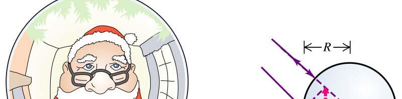
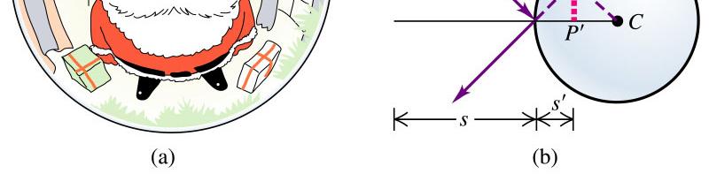
Physics 228 Lecture 3. Today: Spherical Mirrors Lenses.
 Physics 228 Lecture 3 Today: Spherical Mirrors Lenses www.physics.rutgers.edu/ugrad/228 a) Santa as he sees himself in a mirrored sphere. b) Santa as he sees himself in a flat mirror after too much eggnog.
Applications of Optics
 Nicholas J. Giordano www.cengage.com/physics/giordano Chapter 26 Applications of Optics Marilyn Akins, PhD Broome Community College Applications of Optics Many devices are based on the principles of optics
Applied Optics. , Physics Department (Room #36-401) , ,
 , ,") Applied Optics Professor, Physics Department (Room #36-401) 2290-0923, 019-539-0923, shsong@hanyang.ac.kr Office Hours Mondays 15:00-16:30, Wednesdays 15:00-16:30 TA (Ph.D. student, Room #36-415) 2290-0921,
Applied Optics Professor, Physics Department (Room #36-401) 2290-0923, 019-539-0923, shsong@hanyang.ac.kr Office Hours Mondays 15:00-16:30, Wednesdays 15:00-16:30 TA (Ph.D. student, Room #36-415) 2290-0921,
There is a range of distances over which objects will be in focus; this is called the depth of field of the lens. Objects closer or farther are
 Chapter 25 Optical Instruments Some Topics in Chapter 25 Cameras The Human Eye; Corrective Lenses Magnifying Glass Telescopes Compound Microscope Aberrations of Lenses and Mirrors Limits of Resolution
The eye & corrective lenses
 Phys 102 Lecture 20 The eye & corrective lenses 1 Today we will... Apply concepts from ray optics & lenses Simple optical instruments the camera & the eye Learn about the human eye Accommodation Myopia,
University of Rochester Department of Physics and Astronomy Physics123, Spring Homework 5 - Solutions
 Problem 5. University of Rochester Department of Physics and Astronomy Physics23, Spring 202 Homework 5 - Solutions An optometrist finds that a farsighted person has a near point at 25 cm. a) If the eye
CHAPTER 34. Optical Images
 CHAPTER 34 1* Can a virtual image be photographed? Yes. Note that a virtual image is seen because the eye focuses the diverging rays to form a real image on the retina. Similarly, the camera lens can focus
Chapter 23. Mirrors and Lenses
 Chapter 23 Mirrors and Lenses Mirrors and Lenses The development of mirrors and lenses aided the progress of science. It led to the microscopes and telescopes. Allowed the study of objects from microbes
PHYS:1200 LECTURE 31 LIGHT AND OPTICS (3)
") 1 PHYS:1200 LECTURE 31 LIGHT AND OPTICS (3) In lecture 30, we applied the law of reflection to understand how images are formed using plane and curved mirrors. In this lecture we will use the law of refraction
1 PHYS:1200 LECTURE 31 LIGHT AND OPTICS (3) In lecture 30, we applied the law of reflection to understand how images are formed using plane and curved mirrors. In this lecture we will use the law of refraction
Optics of the Human Eye
 Optics of the Human Eye References: Equipment: Ford, Kenneth W., Classical and Modern Physics Vol2 Xerox College Publishing 1972 pp. 900-922. Pasco Human Eye Model Instruction Manual (OS-8477) pp. 1-34.
19. Ray Optics. S. G. Rajeev. April 2, 2009
 9. Ray Optics S. G. Rajeev April 2, 2009 When the wave length is small light travels along straightlines called rays. Ray optics (also called geometrical optics) is the study of this light in this situation.
Physics 102: Lecture 19 Lenses and your EYE Ciliary Muscles
 Physics 02: Lecture 9 Lenses and your EYE Ciliary Muscles Physics 02: Lecture 9, Slide 3 Cases for Converging Lenses Object Past 2F Image Inverted Reduced Real Object Between F & 2F Image Inverted Enlarged
CHAPTER 18 REFRACTION & LENSES
 Physics Approximate Timeline Students are expected to keep up with class work when absent. CHAPTER 18 REFRACTION & LENSES Day Plans for the day Assignments for the day 1 18.1 Refraction of Light o Snell
Lenses- Worksheet. (Use a ray box to answer questions 3 to 7)
") Lenses- Worksheet 1. Look at the lenses in front of you and try to distinguish the different types of lenses? Describe each type and record its characteristics. 2. Using the lenses in front of you, look
Lenses- Worksheet 1. Look at the lenses in front of you and try to distinguish the different types of lenses? Describe each type and record its characteristics. 2. Using the lenses in front of you, look
Lecture 21. Physics 1202: Lecture 21 Today s Agenda
 Physics 1202: Lecture 21 Today s Agenda Announcements: Team problems today Team 14: Gregory Desautels, Benjamin Hallisey, Kyle Mcginnis Team 15: Austin Dion, Nicholas Gandza, Paul Macgillis-Falcon Homework
Physics 222, October 25
 Physics 222, October 25 Key Concepts: Image formation by refraction Thin lenses The eye Optical instruments A single flat interface Images can be formed by refraction, when light traverses a boundary between
2015 EdExcel A Level Physics EdExcel A Level Physics. Lenses
 2015 EdExcel A Level Physics 2015 EdExcel A Level Physics Topic Topic 5 5 Lenses Types of lenses Converging lens bi-convex has two convex surfaces Diverging lens bi-concave has two concave surfaces Thin
Assignment X Light. Reflection and refraction of light. (a) Angle of incidence (b) Angle of reflection (c) principle axis
 Angle of incidence (b) Angle of reflection (c) principle axis") Assignment X Light Reflection of Light: Reflection and refraction of light. 1. What is light and define the duality of light? 2. Write five characteristics of light. 3. Explain the following terms (a)
Assignment X Light Reflection of Light: Reflection and refraction of light. 1. What is light and define the duality of light? 2. Write five characteristics of light. 3. Explain the following terms (a)
Notation for Mirrors and Lenses. Chapter 23. Types of Images for Mirrors and Lenses. More About Images
 Notation for Mirrors and Lenses Chapter 23 Mirrors and Lenses Sections: 4, 6 Problems:, 8, 2, 25, 27, 32 The object distance is the distance from the object to the mirror or lens Denoted by p The image
Chapter 25 Optical Instruments
 Chapter 25 Optical Instruments Units of Chapter 25 Cameras, Film, and Digital The Human Eye; Corrective Lenses Magnifying Glass Telescopes Compound Microscope Aberrations of Lenses and Mirrors Limits of
CH. 23 Mirrors and Lenses HW# 6, 7, 9, 11, 13, 21, 25, 31, 33, 35
 CH. 23 Mirrors and Lenses HW# 6, 7, 9, 11, 13, 21, 25, 31, 33, 35 Mirrors Rays of light reflect off of mirrors, and where the reflected rays either intersect or appear to originate from, will be the location
PHYS 160 Astronomy. When analyzing light s behavior in a mirror or lens, it is helpful to use a technique called ray tracing.
 Optics Introduction In this lab, we will be exploring several properties of light including diffraction, reflection, geometric optics, and interference. There are two sections to this lab and they may
Lecture 3: Geometrical Optics 1. Spherical Waves. From Waves to Rays. Lenses. Chromatic Aberrations. Mirrors. Outline
 Lecture 3: Geometrical Optics 1 Outline 1 Spherical Waves 2 From Waves to Rays 3 Lenses 4 Chromatic Aberrations 5 Mirrors Christoph U. Keller, Leiden Observatory, keller@strw.leidenuniv.nl Lecture 3: Geometrical
Optics Practice. Version #: 0. Name: Date: 07/01/2010
 Optics Practice Date: 07/01/2010 Version #: 0 Name: 1. Which of the following diagrams show a real image? a) b) c) d) e) i, ii, iii, and iv i and ii i and iv ii and iv ii, iii and iv 2. A real image is
Activity 6.1 Image Formation from Spherical Mirrors
 PHY385H1F Introductory Optics Practicals Day 6 Telescopes and Microscopes October 31, 2011 Group Number (number on Intro Optics Kit):. Facilitator Name:. Record-Keeper Name: Time-keeper:. Computer/Wiki-master:..
L. R. & S. M. VISSANJI ACADEMY SECONDARY SECTION PHYSICS-GRADE: VIII OPTICAL INSTRUMENTS
 L. R. & S. M. VISSANJI ACADEMY SECONDARY SECTION - 2016-17 PHYSICS-GRADE: VIII OPTICAL INSTRUMENTS SIMPLE MICROSCOPE A simple microscope consists of a single convex lens of a short focal length. The object
This experiment is under development and thus we appreciate any and all comments as we design an interesting and achievable set of goals.
 Experiment 7 Geometrical Optics You will be introduced to ray optics and image formation in this experiment. We will use the optical rail, lenses, and the camera body to quantify image formation and magnification;
Department of Physics & Astronomy Undergraduate Labs. Thin Lenses
 Thin Lenses Reflection and Refraction When light passes from one medium to another, part of the light is reflected and the rest is transmitted. Light rays that are transmitted undergo refraction (bending)
Final Reg Optics Review SHORT ANSWER. Write the word or phrase that best completes each statement or answers the question.
 Final Reg Optics Review 1) How far are you from your image when you stand 0.75 m in front of a vertical plane mirror? 1) 2) A object is 12 cm in front of a concave mirror, and the image is 3.0 cm in front
c v n = n r Sin n c = n i Refraction of Light Index of Refraction Snell s Law or Refraction Example Problem Total Internal Reflection Optics
 Refraction is the bending of the path of a light wave as it passes from one material into another material. Refraction occurs at the boundary and is caused by a change in the speed of the light wave upon
Chapter 34. Images. Copyright 2014 John Wiley & Sons, Inc. All rights reserved.
 Chapter 34 Images Copyright 34-1 Images and Plane Mirrors Learning Objectives 34.01 Distinguish virtual images from real images. 34.02 Explain the common roadway mirage. 34.03 Sketch a ray diagram for
Physics 1C. Lecture 25B
 Physics 1C Lecture 25B "More than 50 years ago, Austrian researcher Ivo Kohler gave people goggles thats severely distorted their vision: The lenses turned the world upside down. After several weeks, subjects
Optical Systems: Pinhole Camera Pinhole camera: simple hole in a box: Called Camera Obscura Aristotle discussed, Al-Hazen analyzed in Book of Optics
 Optical Systems: Pinhole Camera Pinhole camera: simple hole in a box: Called Camera Obscura Aristotle discussed, Al-Hazen analyzed in Book of Optics 1011CE Restricts rays: acts as a single lens: inverts
Lenses. Optional Reading Stargazer: the life and times of the TELESCOPE, Fred Watson (Da Capo 2004).
.") Lenses Equipment optical bench, incandescent light source, laser, No 13 Wratten filter, 3 lens holders, cross arrow, diffuser, white screen, case of lenses etc., vernier calipers, 30 cm ruler, meter stick
Lenses Equipment optical bench, incandescent light source, laser, No 13 Wratten filter, 3 lens holders, cross arrow, diffuser, white screen, case of lenses etc., vernier calipers, 30 cm ruler, meter stick
Waves & Oscillations
 Physics 42200 Waves & Oscillations Lecture 27 Geometric Optics Spring 205 Semester Matthew Jones Sign Conventions > + = Convex surface: is positive for objects on the incident-light side is positive for
Chapter 23. Mirrors and Lenses
 Chapter 23 Mirrors and Lenses Notation for Mirrors and Lenses The object distance is the distance from the object to the mirror or lens Denoted by p The image distance is the distance from the image to
PHYSICS 289 Experiment 8 Fall Geometric Optics II Thin Lenses
 PHYSICS 289 Experiment 8 Fall 2005 Geometric Optics II Thin Lenses Please look at the chapter on lenses in your text before this lab experiment. Please submit a short lab report which includes answers
Lecture 17. Image formation Ray tracing Calculation. Lenses Convex Concave. Mirrors Convex Concave. Optical instruments
 Lecture 17. Image formation Ray tracing Calculation Lenses Convex Concave Mirrors Convex Concave Optical instruments Image formation Laws of refraction and reflection can be used to explain how lenses
Chapter 25: Applied Optics. PHY2054: Chapter 25
 Chapter 25: Applied Optics PHY2054: Chapter 25 1 Operation of the Eye 24 mm PHY2054: Chapter 25 2 Essential parts of the eye Cornea transparent outer structure Pupil opening for light Lens partially focuses
Physics 142 Lenses and Mirrors Page 1. Lenses and Mirrors. Now for the sequence of events, in no particular order. Dan Rather
 Physics 142 Lenses and Mirrors Page 1 Lenses and Mirrors Now or the sequence o events, in no particular order. Dan Rather Overview: making use o the laws o relection and reraction We will now study ormation
REFLECTION THROUGH LENS
 REFLECTION THROUGH LENS A lens is a piece of transparent optical material with one or two curved surfaces to refract light rays. It may converge or diverge light rays to form an image. Lenses are mostly